EP3155369B1 - Verfahren und system zur messung einer verlagerung einer mobilen plattform - Google Patents
Verfahren und system zur messung einer verlagerung einer mobilen plattform Download PDFInfo
- Publication number
- EP3155369B1 EP3155369B1 EP15871319.8A EP15871319A EP3155369B1 EP 3155369 B1 EP3155369 B1 EP 3155369B1 EP 15871319 A EP15871319 A EP 15871319A EP 3155369 B1 EP3155369 B1 EP 3155369B1
- Authority
- EP
- European Patent Office
- Prior art keywords
- frame
- array
- translation
- mobile platform
- points
- Prior art date
- Legal status (The legal status is an assumption and is not a legal conclusion. Google has not performed a legal analysis and makes no representation as to the accuracy of the status listed.)
- Active
Links
Images


Classifications
-
- G—PHYSICS
- G01—MEASURING; TESTING
- G01C—MEASURING DISTANCES, LEVELS OR BEARINGS; SURVEYING; NAVIGATION; GYROSCOPIC INSTRUMENTS; PHOTOGRAMMETRY OR VIDEOGRAMMETRY
- G01C11/00—Photogrammetry or videogrammetry, e.g. stereogrammetry; Photographic surveying
- G01C11/04—Interpretation of pictures
- G01C11/06—Interpretation of pictures by comparison of two or more pictures of the same area
- G01C11/08—Interpretation of pictures by comparison of two or more pictures of the same area the pictures not being supported in the same relative position as when they were taken
-
- G—PHYSICS
- G01—MEASURING; TESTING
- G01C—MEASURING DISTANCES, LEVELS OR BEARINGS; SURVEYING; NAVIGATION; GYROSCOPIC INSTRUMENTS; PHOTOGRAMMETRY OR VIDEOGRAMMETRY
- G01C21/00—Navigation; Navigational instruments not provided for in groups G01C1/00 - G01C19/00
- G01C21/005—Navigation; Navigational instruments not provided for in groups G01C1/00 - G01C19/00 with correlation of navigation data from several sources, e.g. map or contour matching
-
- G—PHYSICS
- G06—COMPUTING OR CALCULATING; COUNTING
- G06T—IMAGE DATA PROCESSING OR GENERATION, IN GENERAL
- G06T7/00—Image analysis
- G06T7/20—Analysis of motion
- G06T7/246—Analysis of motion using feature-based methods, e.g. the tracking of corners or segments
-
- G—PHYSICS
- G06—COMPUTING OR CALCULATING; COUNTING
- G06T—IMAGE DATA PROCESSING OR GENERATION, IN GENERAL
- G06T7/00—Image analysis
- G06T7/20—Analysis of motion
- G06T7/285—Analysis of motion using a sequence of stereo image pairs
-
- G—PHYSICS
- G06—COMPUTING OR CALCULATING; COUNTING
- G06T—IMAGE DATA PROCESSING OR GENERATION, IN GENERAL
- G06T7/00—Image analysis
- G06T7/97—Determining parameters from multiple pictures
-
- G—PHYSICS
- G06—COMPUTING OR CALCULATING; COUNTING
- G06T—IMAGE DATA PROCESSING OR GENERATION, IN GENERAL
- G06T2207/00—Indexing scheme for image analysis or image enhancement
- G06T2207/10—Image acquisition modality
- G06T2207/10016—Video; Image sequence
- G06T2207/10021—Stereoscopic video; Stereoscopic image sequence
-
- G—PHYSICS
- G06—COMPUTING OR CALCULATING; COUNTING
- G06T—IMAGE DATA PROCESSING OR GENERATION, IN GENERAL
- G06T2207/00—Indexing scheme for image analysis or image enhancement
- G06T2207/10—Image acquisition modality
- G06T2207/10028—Range image; Depth image; 3D point clouds
-
- G—PHYSICS
- G06—COMPUTING OR CALCULATING; COUNTING
- G06T—IMAGE DATA PROCESSING OR GENERATION, IN GENERAL
- G06T2207/00—Indexing scheme for image analysis or image enhancement
- G06T2207/10—Image acquisition modality
- G06T2207/10032—Satellite or aerial image; Remote sensing
Definitions
- the disclosed embodiments relate generally to mobile platform operations and more particularly, but not exclusively, to systems and methods for detecting a displacement of a mobile platform.
- UAVs Unmanned Aerial Vehicles
- Currently-available technologies for measuring the displacement can only ensure performance and precision under certain conditions, such as within a certain height range.
- the currently-available technologies are vulnerable to ambient interferences.
- a solution based on a monocular imaging device and an ultrasonic device can be limited by a detective distance of the ultrasonic device, therefore, normally only applicable within a low altitude of half meter to five meters.
- such monocular solution can also be vulnerable to noises existing in an ambient setting.
- An alternative solution that is based upon a binocular imaging device is limited by a length of a baseline between two lenses of the binocular imaging device and are only applicable within an altitude of one to ten meters.
- Another solution based on a Global Positioning Device (“GPS”) is not reliable under an indoor setting or under a complex ambient setting because of lack of reliable signal.
- EP 2 549 288 A1 describes a method for identifying true feature matches from a plurality of candidate feature matches for vision based navigation.
- a weight for each of the plurality of candidate feature matches can be set.
- the method also includes iteratively performing for N iterations: calculating a fundamental matrix for the plurality of candidate feature matches using a weighted estimation that accounts for the weight of each of the plurality of candidate feature matches; calculating a distance from the fundamental matrix for each of the plurality of candidate feature matches; and updating the weight for each of the plurality of candidate feature matches as a function of the distance for the respective candidate feature match.
- candidate feature matches having a distance less than a distance threshold can be selected as true feature matches.
- Gianpaolo Conte et al. "An integrated UAV Navigation System Based on Aerial Image Matching", 2008 IEEE Aerospace Conference; March 1, 2008, USA, pages 1 to 10 , describes the vision based navigation system which combines inertial sensors, visual odometers and registration of an UAV on-board to a given geo-referenced aerial image and describes to extract position information from aerial imagery when the UAV is flying at low altitude.
- the present invention relates to a method for detecting a displacement of a mobile platform according to independent claim 1 and to an apparatus for detecting a displacement of a mobile platform according to independent claim 9. Exemplary embodiments are described in the dependent claims.
- a mobile platform and method that can meet the requirements of measuring a displacement of the mobile platform during a flight course at various heights under various conditions can prove desirable and provide a basis for accurate measurement of displacements, for systems such as UAV systems and other mobile platforms. This result can be achieved, according to one embodiment disclosed in Fig. 1 .
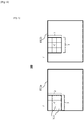
- Fig. 1 illustrates an exemplary schematic diagram of a mobile platform 200.
- the mobile platform 200 can detect a displacement d of the mobile platform 200.
- An imaging device 886 is shown as installed on the mobile platform 200, such as a UAV 250. When the mobile platform 200 is in the air, as shown in Fig. 1 , the imaging device 886 can have a height H and an angle ⁇ relative to a ground level 880.
- the imaging device 886 can comprise a monocular imaging device or a multi-ocular imaging device. In other words, the imaging device 886 can include any suitable number of lenses. Preferably, one lens of the imaging device 886 can be used at selected time points for taking a first and second frames 811a, 811b (shown in Fig.
- the ground level 880 can be the actual ground, a water level or the ground with any structure.
- the imaging device 886 can be at a level 882 as illustrated in Fig. 1 , which level 882 can have a height H.
- the mobile platform 200 can have a first angle relative to the ground level 880 and the imaging device 886 can have a second angle relative to a plane of the mobile platform 200. The first and second angles can be combined into an angle ⁇ of the imaging device 886 relative to the ground level 880.
- the height H can be acquired with a barometer 251 and/or an ultrasonic device 252 (not shown).
- the angle ⁇ can be acquired with a Simultaneous Localization And Mapping (SLAM) device (not shown) in a manner shown and described below with reference to Fig. 5 .
- SLAM Simultaneous Localization And Mapping
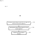
- Fig. 2 illustrates an exemplary embodiment of a method 100 for detecting the displacement d of the mobile platform 200 (collectively shown in Fig. 1 ).
- the method 100 of Fig. 2 is shown as including acquiring a first frame 811a and a second frame 811b, at 810.
- the displacement d of the mobile platform 200 is determined, at 850, based upon the first and second stereoscopic frames 811a, 811b.
- the method 100 can use a monocular imaging system 886 with a SLAM and certain height measurement device, such as a barometer 251 and/or an ultrasonic device 252.
- the two frames 811a, 811b of images are acquired at two different time points: a first time point and a second time point with a travel path of the imaging device 886.
- the first frame 811a and the second frame 811b are stereoscopic frames.
- the two frames 811a, 811b can have at least an overlapping region with a predetermined percentage of the first frame 811a or the second frame 811b.
- the overlapping region of the two frames 811a, 811b is defined as points, on the two frames 811a, 811b, reflecting a same object. To ensure such overlapping region, a time span between the first time point and the second time point can be adjusted so that at least one object can be reflected on both frames 811a, 811b.
- the imaging device 886 stay still relative to the mobile platform 200 or move slowly in order to ensure the overlapping.
- the time span between the first time point and the second time point can be less than one-sixtieth of a second and not greater than one-twentieth of a second.
- the time span can depend on requirements of actual applications or situations. As an exemplary example, when the mobile platform 200 is flying at a lower velocity, the time span can be set to a greater value because an overlapping between the two frames 811a, 811b can be ensured even under the greater time span. On the other hand, when the velocity of the mobile platform 200 is flying at a higher velocity, the time span can be set to a lower value to ensure the overlapping between the two frames 811a, 811b.
- the two frames 811a, 811b are used to calculate a displacement of a mobile platform 200. Such displacement can be calculated in accordance with the manner shown and described below with reference to Figs. 3-5 .
- a system implementing the method 100 advantageously can be applicable to a wide height range of one meter to one hundred meters and can be less vulnerable to any ambient interference.
- the system does not rely on a Global Positioning System ("GPS") signal, therefore, can be applicable in an environment lack of a GPS signal, such as an indoor setting.
- GPS Global Positioning System
- the barometer and the monocular imaging device can be easily installed on a mobile platform, and are preferred to be in installed on a small size UAV.
- Fig. 3 illustrates an alternative embodiment of the method 100.
- movement of the mobile platform 200 (shown in Fig. 1 ) can be calculated.
- a height H of a mobile platform 200 can be calculated based on the two frames 811a, 811b, at 820.
- the height of the mobile platform 200 can be determined with the barometer 251 and/or the ultrasonic device 252.
- the height H of the mobile platform 200 can be acquired before, during or after the first frame 811a and/or the second frame 811b are acquired.
- the second frame 811b is matched to the first frame 811a by matching feature points 355 (shown in Fig. 6 ) on the first frame 811a to certain points on second frames 811a, 811b.
- the two frames 811a, 811b are matched when one or more points, reflecting a same object, on each of the two frames 811a, 811b are found.
- the points reflecting the same object define an overlapping region on the two frames 811a, 811b.
- the feature points 355 on the first frame 811a can be selected from those points reflecting an outstanding object.
- Such object can include, for example, a building, a tree, a road, a river or other type structures.
- the object can be a stable object or a slowly moving object. Additional detail regarding matching the two frames 811a, 811b is shown and described below with reference to Fig. 4 .
- the three translation movements can include translation movements of the mobile platform 200 along each of an x-axis, a y-axis and a z-axis.
- the three rotations can include rotations of the mobile platform 200 around the x-axis, the y-axis and the z-axis, respectively.
- the acquiring the rotations includes use of the IMU 150.
- the translations are calculated based on the rotation data, which is shown and described below with reference to Fig. 5 . Detail regarding calculating the six movements will be provided below with reference to Fig. 5 .
- the displacement of the mobile platform 200 is determined, at 850. Once acquired, the rotations and the translations are applied to calculate the displacement of the mobile platform 200.
- a velocity of the mobile platform 200 can be calculated by dividing the translations by the time span for acquiring the two frames 811a, 811b.
- location information of the mobile platform at a time point can be acquired based upon the calculated translation array T and location information of the mobile platform at a time point for acquiring the first frame 811a. The time point can be a time for acquiring the second frame 811b.
- the next frame of image can be acquired and the system repeats the process in order to calculate the newly acquired frame or frames. The process continues over and over to realize uninterrupted displacement detection.
- Fig. 5 illustrates another alternative embodiment of the method 100.
- matching the two frames 811a, 811b is illustrated.
- two frames 811a, 811b can be acquired via any of the methods shown and described with reference to Fig. 1 , at 810.
- Fig. 4 illustrates one exemplary manner by which the method 100 can match, at 830, the second frame 811b with the first frame 811a.
- the frames 811a, 811b consist of multiple points, and each of those points is represented with x, y and z coordinate values.
- the two frames 811a, 811b described herein can be acquired at different time points along with a travel path of the imaging device 100.
- a stereoscopic point cloud is acquired based on the first frame 811a ⁇ P 1 ,P 2 , P 3 ,..., P n ⁇ , at 832.
- Each point P is a feature point 355 of the first frame 811a.
- the stereoscopic point cloud can be represented with ⁇ (x 1 1 , y 1 1 ), (x 2 1 , y 2 1 ), (x 3 1 , y 3 1 ), ..., (x n 1 , y n 1 ) ⁇ .
- the number of the feature points 355 acquired various based on a processing speed, a size of the frame, a resolution of the frame as well as a calculation capacity of a processor (not shown) etc.
- the number of points, or pixels can be in an exemplarily range of one hundred to two hundred pixels.
- a second projective array is calculated in the second frame 811b ⁇ (x 1 2 , y 1 2 ), (x 2 2 , y 2 2 ), (x 3 2 , y 3 2 ), ..., (x m 2 , y m 2 ) ⁇ , at 834.
- Each of the points (x i 2 , y i 2 ) of the second projective array represents a matched point, projected in an x-y plane, corresponding to a point P j or(x j 1 , y j 1 ) of the stereoscopic point cloud of the first frame 811b.
- a size of the second projective array can be same as a size of the cloud array, in case all points in the cloud array ⁇ P 1 ,P 2 , P 3 ,..., P n ⁇ are matched onto the second frame 811b. However, in most cases, the size of the second projective array is less than the size of the cloud array ⁇ P 1 ,P 2 , P 3 , ...,P n ⁇ because not all points of the first frame 811a can be matched onto the second frame 811b. Matching of the stereoscopic point cloud of the first frame 811a to the second frame 811b can be accomplished by the method 100 described with reference to Figs. 6-8 , in which three-by-three pixels are compared to determine the similarity of two points.
- an IMU 150 (not shown) is configured to measure rotation measurements that can be passed to a processor(not shown).
- the rotation measurements can be represented by a three dimensional array R.
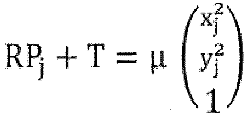
- R P j + T ⁇ x j y j 1
- R is a three-dimensional array representing the rotation measurements
- Pj is a point of the first frame 811a
- T represents a three-dimensional array of translation of the second frame 811b to be calculated
- ⁇ is a random number acting as a factor.
- the interval between the first time point when the first frame 811a can be taken and the second time point when the second frame 811b can be taken can be relatively short.
- the time interval between the first frame 811a and the second frame 811b usually can be within a range of twentieth to sixtieth seconds depending on the requirements of actual applications, as described with reference to Fig. 2 .
- Equation 6 three unknowns (Tx, Ty, Tz) exist; therefore, by mathematical principles, three equations can be needed to jointly solve the calculated translation array T with the three unknowns, at 844.
- each of the projected points has only two values in x i and y i . So, in order to resolve three unknowns in the calculated translation array T, three equations out of four equations available for two such points can be joined.
- the calculated translation array T can be inaccurate.
- the calculated translation array T can be introduced into the Equation 6, and calculated to determine the number of points that conform to the relationship defined in the equation. Then, another pair of points is used in solving the calculated translation array T, at 844, which is then used to calculate to determine the number of points that conform to the relationship of Equation 6 at 846. This process can iterate for a predetermined number of pairs of points, and the results are a predetermined number of the calculated translation arrays T accompanied with a number of points of conformance to Equation 6 for each translation array.
- the numbers of conformed points is compared among the calculated translation arrays T.
- a calculated translation array T with the greatest number of conformed points can be chosen. The process described with reference to Fig. 4 can be repeated again and again to perform continuous displacement detection.
- Fig. 6 illustrates an exemplary embodiment of a method 300 for matching a point of the second frame 811b with a corresponding point 355 of the first frame 811a.
- a three-by-three pixel block is taken with the compared point in the center from each of the frames 811a, 811b.
- the first and second frames 811a and 811b are color images, values of color components can be compared for each pixel of the three-by-three pixel block.
- the frames 811a and 811b are black and white images, greyscale values for each pixel can be compared.
- the point with smallest sum of value differences for all nine pixels can be selected as the matching point. This process can be repeated for all selected feature points on the first frame 811a.
- a method of using Binary Robust Independent Elementary Features (“BRIEF”) descriptors can be used for matching the point of the second frame 811b with the corresponding point 355 of the first frame 811a.
- BRIEF Binary Robust Independent Elementary Features
- a first binary string representing a first region around the selected feature point of the first frame 811a, can be built by comparing intensities of each point pairs of the region.
- the first binary string can be the first BRIEF descriptor of the selected feature point of the first frame 811a.
- a second binary string representing a second region around the point 355 of the second frame 811b can be built by comparing intensities of each point pairs of the second region.
- the second binary string can be a second BRIEF descriptor.
- a similarity between the selected feature point of the first frame 811a and the point 355 of the second frame 811b can be calculated by comparing a hamming distance between the first BRIEF descriptor and the second BRIEF descriptor.
- the point 355 of the second frame 811b can be determined as matching the selected feature point of the first frame 811a when a hamming distance between the first BRIEF descriptor and the second BRIEF descriptor is less than a first hamming threshold.
- a plurality of feature points 355 on the object 198 of interest can be selected.
- the feature points 355 can be selected using one or more of a variety of different methods.
- the feature points 355 can be identified as pre-defined shapes of the object 198 of interest.
- the feature points 355 can be recognized as one or more portions of the object 198 of interest having a particular color or intensity.
- the feature points 355 can be selected as random portions of the object 198 of interest.
- the feature points 355 can be selected at regularly spaced intervals on the object 198 of interest, for example, every pixel, every other pixel, every third pixel, every fourth pixel, and so forth.
- the feature points 355 can take varying shapes and sizes, as desired.
- a combination of methods described above can be used to select the feature points 355.
- the selected feature points 355 can be matched from the first frame 811a onto the second frame 811b.
- matching of the feature points 355 consists of two procedures as shown in Fig. 8 .
- a feature point 355 of the first frame 811a can selected.
- a matching point can be scanned starting from a calculated point and along a line parallel to the centered line of a lens (not shown) being used to capture the two frames 811a, 811b.
- the matching starting point can be calculated based on the coordinates of the point on the first frame 811a.
- the scanning can be performed in any of one or more predetermined directions.
- a feature disparity d between each feature points 355 of the two frames 811a and 811b can be found, at 926. Any of a variety of methods can be used to determine the disparity d.
- the disparity d can be found based on an average of the disparities d for each of the feature points 355. Exemplary types of averages can include an arithmetic mean, a geometric mean, a median, and/or a mode without limitation.
- the disparity d can be found by selecting one or more of the feature points 355 and acquiring the disparity d based on the selected feature points 355.
Landscapes
- Engineering & Computer Science (AREA)
- Physics & Mathematics (AREA)
- General Physics & Mathematics (AREA)
- Radar, Positioning & Navigation (AREA)
- Remote Sensing (AREA)
- Multimedia (AREA)
- Computer Vision & Pattern Recognition (AREA)
- Theoretical Computer Science (AREA)
- Automation & Control Theory (AREA)
- Length Measuring Devices By Optical Means (AREA)
- Image Analysis (AREA)
- Navigation (AREA)
Claims (11)
- Verfahren zum Detektieren eines Versatzes einer mobilen Plattform (200), das Folgendes umfasst:Erhalten eines ersten Rahmens (811a) und eines zweiten Rahmens (811b) mit einer Bildgebungsvorrichtung (886) undBestimmen des Versatzes der mobilen Plattform (200) auf Basis des ersten Rahmens (811a) und des zweiten Rahmens (811b),wobei das Erhalten das Erfassen einer Höhe der mobilen Plattform (200) umfasst,wobei das Erhalten das Erfassen eines Winkels der Bildgebungsvorrichtung (886) mit Bezug auf ein Bodenniveau (880) umfasst,wobei das Erfassen des Winkels das Erfassen des Winkels via eine inertiale Messeinheit ("IMU") umfasst,wobei das Erhalten ferner Folgendes umfasst:Messen eines Rotationswinkels der mobilen Plattform (200) mit der IMU relativ zum ersten Rahmen (811a), um Rotationsdaten zu erzeugen;Erfassen einer stereoskopischen Punktwolke auf Basis des ersten Rahmens (811a), wobei die stereoskopische Punktwolke ein Array von Merkmalspunkten {PI, P2, P3, ..., Pn } ist;Erfassen eines zweiten projektiven Arrays in einer x-y-Ebene {(x1 2, y1 2), (x2 2, y2 2), (x3 2, y3 2), ..., (xm 2, ym 2)} des zweiten Rahmens (811b) auf Basis der stereoskopischen Punktwolke, wobei das Erfassen des zweiten projektiven Arrays Folgendes umfasst:Erfassen eines ersten projektiven Arrays in einer x-y-Ebene {(x1 1, y1 1), (x2 1, y2 1), (x3 1, y3 1), ... (xn 1, yn 1)} des ersten Rahmens (811a) auf Basis der stereoskopischen Punktwolke undAbgleichen einer Vielzahl von Merkmalspunkten des ersten projektiven Arrays auf dem zweiten Rahmen (811b), um das zweite projektive Array {(x1 2, y1 2), (x2 2, y2 2), (x3 2, y3 2), ..., (xm 2, ym 2)} zu erzeugen;Bestimmen eines Translationsarrays T auf Basis der Rotationsdaten, der stereoskopischen Punktwolke und des zweiten projektiven Arrays undBerechnen des Versatzes der mobilen Plattform (200) auf Basis des Translationsarrays T,wobei das Verfahren dadurch gekennzeichnet ist, dass das Berechnen des Translationsarrays T Folgendes umfasst:Berechnen einer vorbestimmten Anzahl von Translationsarrays auf Basis einer Beziehung zwischen den Rotationsdaten und einer vorbestimmten Anzahl von Paaren eines Merkmalspunktes und eines entsprechenden übereinstimmenden Punktes, wobei jedes Translationsarray der vorbestimmten Anzahl von Translationsarrays durch Lösen eines Satzes von Gleichungen für mindestens zwei Merkmalspunkte, die aus der stereoskopischen Punktwolke ausgewählt werden, und deren übereinstimmenden Punkten im zweiten projektiven Array berechnet wird;Berechnen einer Anzahl von abgeglichenen Merkmalspunkten, die mit der Beziehung konform sind, für jedes Translationsarray durch Einbringen jedes Translationsarrays in die Beziehung undAuswählen eines Translationsarrays aus der vorbestimmten Anzahl von Translationsarrays mit einer maximalen Anzahl von abgeglichenen Merkmalspunkten als das Translationsarray T.
- Verfahren nach Anspruch 1, wobei die Höhe mit einem Barometer (251) und einer Ultraschallvorrichtung (252) erfasst wird.
- Verfahren nach Anspruch 1, wobei das Erhalten ferner das Abgleichen des ersten und des zweiten Rahmens (811a, 811b) umfasst,
wobei der erste Rahmen (811a) den zweiten Rahmen (811b) überlappt. - Verfahren nach Anspruch 3, wobei das Erhalten das Erfassen des ersten Rahmens (811a) und des zweiten Rahmens (811b) zu verschiedenen Zeitpunkten umfasst.
- Verfahren nach Anspruch 1 oder 4, wobei das Abgleichen der Vielzahl von Merkmalspunkten Folgendes umfasst:Abtasten des zweiten Rahmens (811b), um einen Punkt des zweiten Rahmens (811b) zu identifizieren, der mit einem ausgewählten Merkmalspunkt des ersten Rahmens (811a) übereinstimmt; undBerechnen einer Ähnlichkeit zwischen dem ausgewählten Merkmalspunkt des ersten Rahmens (811a) und dem Punkt.
- Verfahren nach Anspruch 1 oder 5, wobei das Berechnen des jeweiligen Translationsarrays T das Anwenden der folgenden Beziehung umfasst:

- Verfahren nach Anspruch 6, wobei das Anwenden von
- Verfahren nach einem der Ansprüche 6 bis 7, das ferner Folgendes umfasst:
Verifizieren des Translationsarrays T durch Einbringen von T in die Gleichung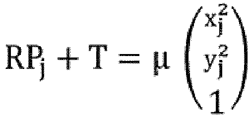
- Einrichtung zum Detektieren eines Versatzes einer mobilen Plattform (200), die Folgendes umfasst:eine Bildgebungsvorrichtung (886) zum Erhalten eines ersten Rahmens (811a) und eines zweiten Rahmens (811b) undeinen Prozessor zum Bestimmen des Versatzes der mobilen Plattform (200) auf Basis des ersten Rahmens (811a) und des zweiten Rahmens (811b),wobei der Prozessor zu Folgendem ausgelegt ist:Erfassen einer Höhe der mobilen Plattform (200);Erfassen eines Winkels der Bildgebungsvorrichtung (886) mit Bezug auf ein Bodenniveau (880),wobei der Winkel der mobilen Plattform (200) via eine inertiale Messeinheit ("IMU") erfasst wird;Messen eines Rotationswinkels der mobilen Plattform (200) mit der IMU relativ zum ersten Rahmen (811a), um Rotationsdaten zu erzeugen;Erfassen einer stereoskopischen Punktwolke auf Basis des ersten Rahmens (811a),wobei die stereoskopische Punktwolke ein Array von Merkmalspunkten {PI, P2, P3 ,..., Pn } ist;Erfassen eines zweiten projektiven Arrays in einer x-y-Ebene {(x1 2, y1 2), (x2 2, y2 2), (x3 2, y3 2), ..., (xm 2, ym 2)} des zweiten Rahmens (811b) auf Basis der stereoskopischen Punktwolke,wobei das Erfassen des zweiten projektiven Arrays Folgendes umfasst:Erfassen eines ersten projektiven Arrays in einer x-y-Ebene {(x1 1, y1 1), (x2 1, y2 1), (x3 1, y3 1), ... (xn 1, yn 1)} des ersten Rahmens (811a) auf Basis der stereoskopischen Punktwolke undAbgleichen einer Vielzahl von Merkmalspunkten des ersten projektiven Arrays auf dem zweiten Rahmen (811b), um das zweite projektive Array {(x1 2, y1 2), (x2 2, y2 2, (x3 2, y3 2), ..., (xm 2, ym 2)} zu erzeugen;Bestimmen eines Translationsarrays T auf Basis der Rotationsdaten, der stereoskopischen Punktwolke und des zweiten projektiven Arrays undBerechnen des Versatzes der mobilen Plattform auf Basis des Translationsarrays T;wobei die Einrichtung dadurch gekennzeichnet ist, dass das Berechnen des Translationsarrays T Folgendes umfasst:Berechnen einer vorbestimmten Anzahl von Translationsarrays auf Basis einer Beziehung zwischen den Rotationsdaten und einer vorbestimmten Anzahl von Paaren eines Merkmalspunktes und eines entsprechenden übereinstimmenden Punktes, wobei jedes Translationsarray der vorbestimmten Anzahl von Translationsarrays durch Lösen eines Satzes von Gleichungen für mindestens zwei Merkmalspunkte, die aus der stereoskopischen Punktwolke ausgewählt werden, und deren übereinstimmende Punkte im zweiten projektiven Array berechnet wird;Berechnen einer Anzahl von abgeglichenen Merkmalspunkten, die mit der Beziehung konform sind, für jedes Translationsarray durch Einbringen jedes Translationsarrays in die Beziehung undAuswählen eines Translationsarrays aus der vorbestimmten Anzahl von Translationsarrays mit einer maximalen Anzahl von abgeglichenen Merkmalspunkten als das Translationsarray T.
- Einrichtung nach Anspruch 9, wobei der Prozessor dazu ausgelegt ist, den ersten und den zweiten Rahmen (811a, 811b) abzugleichen,
wobei der erste Rahmen (811a) den zweiten Rahmen (811b) überlappt. - Einrichtung nach Anspruch 9, wobei der erste Rahmen (811a) und der zweite Rahmen (811b) zu verschiedenen Zeitpunkten erfasst werden.
Applications Claiming Priority (1)
| Application Number | Priority Date | Filing Date | Title |
|---|---|---|---|
| PCT/CN2015/082525 WO2016206108A1 (en) | 2015-06-26 | 2015-06-26 | System and method for measuring a displacement of a mobile platform |
Publications (3)
| Publication Number | Publication Date |
|---|---|
| EP3155369A1 EP3155369A1 (de) | 2017-04-19 |
| EP3155369A4 EP3155369A4 (de) | 2017-07-19 |
| EP3155369B1 true EP3155369B1 (de) | 2020-03-18 |
Family
ID=57584400
Family Applications (1)
| Application Number | Title | Priority Date | Filing Date |
|---|---|---|---|
| EP15871319.8A Active EP3155369B1 (de) | 2015-06-26 | 2015-06-26 | Verfahren und system zur messung einer verlagerung einer mobilen plattform |
Country Status (6)
| Country | Link |
|---|---|
| US (3) | US10527416B2 (de) |
| EP (1) | EP3155369B1 (de) |
| JP (1) | JP6333396B2 (de) |
| CN (1) | CN106489062B (de) |
| ES (1) | ES2788479T3 (de) |
| WO (1) | WO2016206108A1 (de) |
Families Citing this family (7)
| Publication number | Priority date | Publication date | Assignee | Title |
|---|---|---|---|---|
| JP6333396B2 (ja) * | 2015-06-26 | 2018-05-30 | エスゼット ディージェイアイ テクノロジー カンパニー リミテッドSz Dji Technology Co.,Ltd | モバイルプラットフォームの変位を計測する方法及び装置 |
| KR20180068411A (ko) * | 2016-12-14 | 2018-06-22 | 삼성전자주식회사 | 무인 비행 전자 장치의 운행 제어 방법 및 이를 지원하는 전자 장치 |
| US10365650B2 (en) * | 2017-05-25 | 2019-07-30 | GM Global Technology Operations LLC | Methods and systems for moving object velocity determination |
| US10641900B2 (en) * | 2017-09-15 | 2020-05-05 | Aeye, Inc. | Low latency intra-frame motion estimation based on clusters of ladar pulses |
| CN110741625B (zh) * | 2018-07-23 | 2022-06-21 | 深圳市大疆创新科技有限公司 | 运动估计方法及摄影器材 |
| WO2021226764A1 (zh) * | 2020-05-09 | 2021-11-18 | 深圳市大疆创新科技有限公司 | 测距装置、测距方法及可移动平台 |
| US11808578B2 (en) * | 2020-05-29 | 2023-11-07 | Aurora Flight Sciences Corporation | Global positioning denied navigation |
Family Cites Families (36)
| Publication number | Priority date | Publication date | Assignee | Title |
|---|---|---|---|---|
| JP2001039397A (ja) * | 1999-08-02 | 2001-02-13 | Komatsu Ltd | 水平回転翼を有した飛翔体 |
| JP4672175B2 (ja) * | 2000-05-26 | 2011-04-20 | 本田技研工業株式会社 | 位置検出装置、位置検出方法、及び位置検出プログラム |
| US9229540B2 (en) * | 2004-01-30 | 2016-01-05 | Electronic Scripting Products, Inc. | Deriving input from six degrees of freedom interfaces |
| CN1670479A (zh) * | 2004-03-15 | 2005-09-21 | 清华大学 | 基于视频图像测量飞行器飞行高度的方法 |
| US8666661B2 (en) * | 2006-03-31 | 2014-03-04 | The Boeing Company | Video navigation |
| US8306747B1 (en) * | 2007-01-19 | 2012-11-06 | Starodub, Inc. | Travel way measurement system |
| US20080195316A1 (en) * | 2007-02-12 | 2008-08-14 | Honeywell International Inc. | System and method for motion estimation using vision sensors |
| KR100882011B1 (ko) * | 2007-07-29 | 2009-02-04 | 주식회사 나노포토닉스 | 회전 대칭형의 광각 렌즈를 이용하여 전방위 영상을 얻는 방법 및 장치 |
| US7970507B2 (en) * | 2008-01-23 | 2011-06-28 | Honeywell International Inc. | Method and system for autonomous tracking of a mobile target by an unmanned aerial vehicle |
| FR2927262B1 (fr) * | 2008-02-13 | 2014-11-28 | Parrot | Procede de pilotage d'un drone a voilure tournante |
| WO2010045271A1 (en) * | 2008-10-14 | 2010-04-22 | Joshua Victor Aller | Target and method of detecting, identifying, and determining 3-d pose of the target |
| CN101876535B (zh) * | 2009-12-02 | 2015-11-25 | 北京中星微电子有限公司 | 一种高度测量方法、装置及监控系统 |
| US9147260B2 (en) * | 2010-12-20 | 2015-09-29 | International Business Machines Corporation | Detection and tracking of moving objects |
| US9758239B2 (en) * | 2011-04-14 | 2017-09-12 | Hexagon Technology Center Gmbh | System and method for controlling an unmanned air vehicle |
| US8447116B2 (en) * | 2011-07-22 | 2013-05-21 | Honeywell International Inc. | Identifying true feature matches for vision based navigation |
| WO2013062557A1 (en) * | 2011-10-27 | 2013-05-02 | The Boeing Company | Stereo video movies |
| JP6041535B2 (ja) * | 2012-05-29 | 2016-12-07 | 株式会社トプコン | 画像取得方法及び撮影装置 |
| DE102012209316A1 (de) * | 2012-06-01 | 2013-12-05 | Robert Bosch Gmbh | Verfahren und Vorrichtung zum Verarbeiten von Sensordaten eines Stereosensorsystems |
| JP6055274B2 (ja) * | 2012-10-31 | 2016-12-27 | 株式会社トプコン | 航空写真測定方法及び航空写真測定システム |
| US9070289B2 (en) * | 2013-05-10 | 2015-06-30 | Palo Alto Research Incorporated | System and method for detecting, tracking and estimating the speed of vehicles from a mobile platform |
| US9584981B2 (en) * | 2014-08-27 | 2017-02-28 | Qualcomm Incorporated | Method and apparatus for real-time, mobile-based positioning according to sensor and radio frequency measurements |
| DE102014224884B4 (de) * | 2014-12-04 | 2025-01-16 | Jungheinrich Aktiengesellschaft | Logistikeinrichtung |
| US9689976B2 (en) * | 2014-12-19 | 2017-06-27 | Xidrone Systems, Inc. | Deterent for unmanned aerial systems |
| US9830503B1 (en) * | 2014-12-31 | 2017-11-28 | Morphotrust Usa, Llc | Object detection in videos |
| KR101738750B1 (ko) * | 2015-06-11 | 2017-05-24 | 한국과학기술원 | 실외 환경에서의 강인한 위치 인식 방법 및 장치 |
| JP6333396B2 (ja) * | 2015-06-26 | 2018-05-30 | エスゼット ディージェイアイ テクノロジー カンパニー リミテッドSz Dji Technology Co.,Ltd | モバイルプラットフォームの変位を計測する方法及び装置 |
| CN105117022A (zh) * | 2015-09-24 | 2015-12-02 | 北京零零无限科技有限公司 | 一种控制无人机随脸转动的方法和装置 |
| CN105447853B (zh) * | 2015-11-13 | 2018-07-13 | 深圳市道通智能航空技术有限公司 | 飞行装置、飞行控制系统及方法 |
| JP2017100651A (ja) * | 2015-12-04 | 2017-06-08 | 株式会社Soken | 飛行装置 |
| US11022407B2 (en) * | 2015-12-15 | 2021-06-01 | Tradewinds Technology, Llc | UAV defense system |
| EP3438775A1 (de) * | 2016-03-31 | 2019-02-06 | Nikon Corporation | Flugvorrichtung, elektronische vorrichtung und programm |
| US10112715B2 (en) * | 2016-04-26 | 2018-10-30 | Hewlett-Packard Development Company, L.P. | Signaling print substances |
| ES2893959T3 (es) * | 2016-08-26 | 2022-02-10 | Sz Dji Technology Co Ltd | Métodos y sistema de aterrizaje autónomo |
| US9794516B1 (en) * | 2016-11-16 | 2017-10-17 | Raja Singh Tuli | Telepresence system |
| JP6790932B2 (ja) * | 2017-03-14 | 2020-11-25 | 富士通株式会社 | 飛行体運用システム、クレーン装置制御方法、及び制御プログラム |
| JP6963923B2 (ja) * | 2017-07-06 | 2021-11-10 | 株式会社トプコン | レーザスキャナ及び測量システム |
-
2015
- 2015-06-26 JP JP2016550777A patent/JP6333396B2/ja not_active Expired - Fee Related
- 2015-06-26 EP EP15871319.8A patent/EP3155369B1/de active Active
- 2015-06-26 ES ES15871319T patent/ES2788479T3/es active Active
- 2015-06-26 WO PCT/CN2015/082525 patent/WO2016206108A1/en not_active Ceased
- 2015-06-26 CN CN201580034026.0A patent/CN106489062B/zh not_active Expired - Fee Related
-
2017
- 2017-12-15 US US15/844,341 patent/US10527416B2/en not_active Expired - Fee Related
-
2020
- 2020-01-03 US US16/733,550 patent/US10760907B2/en active Active
- 2020-08-27 US US17/004,513 patent/US11346666B2/en active Active
Non-Patent Citations (1)
| Title |
|---|
| None * |
Also Published As
| Publication number | Publication date |
|---|---|
| US20200393246A1 (en) | 2020-12-17 |
| WO2016206108A1 (en) | 2016-12-29 |
| EP3155369A1 (de) | 2017-04-19 |
| ES2788479T3 (es) | 2020-10-21 |
| US20200149887A1 (en) | 2020-05-14 |
| CN106489062A (zh) | 2017-03-08 |
| JP6333396B2 (ja) | 2018-05-30 |
| US20180112979A1 (en) | 2018-04-26 |
| US10760907B2 (en) | 2020-09-01 |
| US10527416B2 (en) | 2020-01-07 |
| CN106489062B (zh) | 2019-06-28 |
| US11346666B2 (en) | 2022-05-31 |
| EP3155369A4 (de) | 2017-07-19 |
| JP2017524122A (ja) | 2017-08-24 |
Similar Documents
| Publication | Publication Date | Title |
|---|---|---|
| EP3155369B1 (de) | Verfahren und system zur messung einer verlagerung einer mobilen plattform | |
| CN111156998B (zh) | 一种基于rgb-d相机与imu信息融合的移动机器人定位方法 | |
| US10120068B1 (en) | Calibration of laser sensors | |
| US12315196B2 (en) | Determining position using computer vision, lidar, and trilateration | |
| JP5832341B2 (ja) | 動画処理装置、動画処理方法および動画処理用のプログラム | |
| US11151741B2 (en) | System and method for obstacle avoidance | |
| US20200003878A1 (en) | Calibration of laser and vision sensors | |
| JP5992184B2 (ja) | 画像データ処理装置、画像データ処理方法および画像データ処理用のプログラム | |
| JP5762131B2 (ja) | キャリブレーション装置、キャリブレーション装置のキャリブレーション方法およびキャリブレーションプログラム | |
| EP2175237B1 (de) | System und Verfahren zur bildbasierten Navigation mithilfe der Übereinstimmung von Linienmerkmale | |
| JP6321202B2 (ja) | モバイルプラットフォームの運動を決定する方法、装置、及びシステム | |
| WO2017037697A1 (en) | System and method for self-geoposition unmanned aerial vehicle | |
| US10730618B2 (en) | System and method for selecting an operation mode of a mobile platform | |
| CN117330052A (zh) | 基于红外视觉、毫米波雷达和imu融合的定位与建图方法及系统 | |
| KR101821992B1 (ko) | 무인비행체를 이용한 목표물의 3차원 위치 산출 방법 및 장치 | |
| CN119104050A (zh) | 载体位置的确定方法、装置、计算机设备及存储介质 | |
| Igaue et al. | Cooperative 3D tunnel measurement based on 2D–3D registration of omnidirectional laser light | |
| KR102717557B1 (ko) | 영상 기반 속도 연산 시스템 | |
| JP2024005342A (ja) | 情報処理装置、情報処理方法、及びコンピュータプログラム | |
| Burschka | Monocular navigation in large scale dynamic environments | |
| JP2020042854A (ja) | モバイルプラットフォームの動作モードを選択するシステム及び方法 |
Legal Events
| Date | Code | Title | Description |
|---|---|---|---|
| STAA | Information on the status of an ep patent application or granted ep patent |
Free format text: STATUS: THE INTERNATIONAL PUBLICATION HAS BEEN MADE |
|
| PUAI | Public reference made under article 153(3) epc to a published international application that has entered the european phase |
Free format text: ORIGINAL CODE: 0009012 |
|
| STAA | Information on the status of an ep patent application or granted ep patent |
Free format text: STATUS: THE APPLICATION HAS BEEN PUBLISHED |
|
| AK | Designated contracting states |
Kind code of ref document: A1 Designated state(s): AL AT BE BG CH CY CZ DE DK EE ES FI FR GB GR HR HU IE IS IT LI LT LU LV MC MK MT NL NO PL PT RO RS SE SI SK SM TR |
|
| AX | Request for extension of the european patent |
Extension state: BA ME |
|
| REG | Reference to a national code |
Ref country code: DE Ref legal event code: R079 Ref document number: 602015049179 Country of ref document: DE Free format text: PREVIOUS MAIN CLASS: G01C0011040000 Ipc: G01C0011080000 |
|
| A4 | Supplementary search report drawn up and despatched |
Effective date: 20170620 |
|
| RIC1 | Information provided on ipc code assigned before grant |
Ipc: G01C 21/00 20060101ALI20170613BHEP Ipc: G05D 1/02 20060101ALI20170613BHEP Ipc: G06T 7/246 20170101ALI20170613BHEP Ipc: G01C 11/08 20060101AFI20170613BHEP |
|
| STAA | Information on the status of an ep patent application or granted ep patent |
Free format text: STATUS: REQUEST FOR EXAMINATION WAS MADE |
|
| 17P | Request for examination filed |
Effective date: 20160630 |
|
| DAV | Request for validation of the european patent (deleted) | ||
| DAX | Request for extension of the european patent (deleted) | ||
| STAA | Information on the status of an ep patent application or granted ep patent |
Free format text: STATUS: EXAMINATION IS IN PROGRESS |
|
| 17Q | First examination report despatched |
Effective date: 20190429 |
|
| GRAP | Despatch of communication of intention to grant a patent |
Free format text: ORIGINAL CODE: EPIDOSNIGR1 |
|
| STAA | Information on the status of an ep patent application or granted ep patent |
Free format text: STATUS: GRANT OF PATENT IS INTENDED |
|
| RIN1 | Information on inventor provided before grant (corrected) |
Inventor name: ZHANG, HONGHUI |
|
| INTG | Intention to grant announced |
Effective date: 20191030 |
|
| GRAS | Grant fee paid |
Free format text: ORIGINAL CODE: EPIDOSNIGR3 |
|
| GRAA | (expected) grant |
Free format text: ORIGINAL CODE: 0009210 |
|
| STAA | Information on the status of an ep patent application or granted ep patent |
Free format text: STATUS: THE PATENT HAS BEEN GRANTED |
|
| AK | Designated contracting states |
Kind code of ref document: B1 Designated state(s): AL AT BE BG CH CY CZ DE DK EE ES FI FR GB GR HR HU IE IS IT LI LT LU LV MC MK MT NL NO PL PT RO RS SE SI SK SM TR |
|
| REG | Reference to a national code |
Ref country code: GB Ref legal event code: FG4D |
|
| REG | Reference to a national code |
Ref country code: DE Ref legal event code: R096 Ref document number: 602015049179 Country of ref document: DE |
|
| REG | Reference to a national code |
Ref country code: AT Ref legal event code: REF Ref document number: 1246401 Country of ref document: AT Kind code of ref document: T Effective date: 20200415 Ref country code: IE Ref legal event code: FG4D |
|
| REG | Reference to a national code |
Ref country code: NL Ref legal event code: FP |
|
| PG25 | Lapsed in a contracting state [announced via postgrant information from national office to epo] |
Ref country code: RS Free format text: LAPSE BECAUSE OF FAILURE TO SUBMIT A TRANSLATION OF THE DESCRIPTION OR TO PAY THE FEE WITHIN THE PRESCRIBED TIME-LIMIT Effective date: 20200318 Ref country code: FI Free format text: LAPSE BECAUSE OF FAILURE TO SUBMIT A TRANSLATION OF THE DESCRIPTION OR TO PAY THE FEE WITHIN THE PRESCRIBED TIME-LIMIT Effective date: 20200318 Ref country code: NO Free format text: LAPSE BECAUSE OF FAILURE TO SUBMIT A TRANSLATION OF THE DESCRIPTION OR TO PAY THE FEE WITHIN THE PRESCRIBED TIME-LIMIT Effective date: 20200618 |
|
| PG25 | Lapsed in a contracting state [announced via postgrant information from national office to epo] |
Ref country code: BG Free format text: LAPSE BECAUSE OF FAILURE TO SUBMIT A TRANSLATION OF THE DESCRIPTION OR TO PAY THE FEE WITHIN THE PRESCRIBED TIME-LIMIT Effective date: 20200618 Ref country code: SE Free format text: LAPSE BECAUSE OF FAILURE TO SUBMIT A TRANSLATION OF THE DESCRIPTION OR TO PAY THE FEE WITHIN THE PRESCRIBED TIME-LIMIT Effective date: 20200318 Ref country code: LV Free format text: LAPSE BECAUSE OF FAILURE TO SUBMIT A TRANSLATION OF THE DESCRIPTION OR TO PAY THE FEE WITHIN THE PRESCRIBED TIME-LIMIT Effective date: 20200318 Ref country code: HR Free format text: LAPSE BECAUSE OF FAILURE TO SUBMIT A TRANSLATION OF THE DESCRIPTION OR TO PAY THE FEE WITHIN THE PRESCRIBED TIME-LIMIT Effective date: 20200318 Ref country code: GR Free format text: LAPSE BECAUSE OF FAILURE TO SUBMIT A TRANSLATION OF THE DESCRIPTION OR TO PAY THE FEE WITHIN THE PRESCRIBED TIME-LIMIT Effective date: 20200619 |
|
| REG | Reference to a national code |
Ref country code: LT Ref legal event code: MG4D |
|
| REG | Reference to a national code |
Ref country code: ES Ref legal event code: FG2A Ref document number: 2788479 Country of ref document: ES Kind code of ref document: T3 Effective date: 20201021 |
|
| PG25 | Lapsed in a contracting state [announced via postgrant information from national office to epo] |
Ref country code: PT Free format text: LAPSE BECAUSE OF FAILURE TO SUBMIT A TRANSLATION OF THE DESCRIPTION OR TO PAY THE FEE WITHIN THE PRESCRIBED TIME-LIMIT Effective date: 20200812 Ref country code: SM Free format text: LAPSE BECAUSE OF FAILURE TO SUBMIT A TRANSLATION OF THE DESCRIPTION OR TO PAY THE FEE WITHIN THE PRESCRIBED TIME-LIMIT Effective date: 20200318 Ref country code: EE Free format text: LAPSE BECAUSE OF FAILURE TO SUBMIT A TRANSLATION OF THE DESCRIPTION OR TO PAY THE FEE WITHIN THE PRESCRIBED TIME-LIMIT Effective date: 20200318 Ref country code: SK Free format text: LAPSE BECAUSE OF FAILURE TO SUBMIT A TRANSLATION OF THE DESCRIPTION OR TO PAY THE FEE WITHIN THE PRESCRIBED TIME-LIMIT Effective date: 20200318 Ref country code: RO Free format text: LAPSE BECAUSE OF FAILURE TO SUBMIT A TRANSLATION OF THE DESCRIPTION OR TO PAY THE FEE WITHIN THE PRESCRIBED TIME-LIMIT Effective date: 20200318 Ref country code: IS Free format text: LAPSE BECAUSE OF FAILURE TO SUBMIT A TRANSLATION OF THE DESCRIPTION OR TO PAY THE FEE WITHIN THE PRESCRIBED TIME-LIMIT Effective date: 20200718 Ref country code: CZ Free format text: LAPSE BECAUSE OF FAILURE TO SUBMIT A TRANSLATION OF THE DESCRIPTION OR TO PAY THE FEE WITHIN THE PRESCRIBED TIME-LIMIT Effective date: 20200318 Ref country code: LT Free format text: LAPSE BECAUSE OF FAILURE TO SUBMIT A TRANSLATION OF THE DESCRIPTION OR TO PAY THE FEE WITHIN THE PRESCRIBED TIME-LIMIT Effective date: 20200318 |
|
| REG | Reference to a national code |
Ref country code: AT Ref legal event code: MK05 Ref document number: 1246401 Country of ref document: AT Kind code of ref document: T Effective date: 20200318 |
|
| REG | Reference to a national code |
Ref country code: DE Ref legal event code: R097 Ref document number: 602015049179 Country of ref document: DE |
|
| PLBE | No opposition filed within time limit |
Free format text: ORIGINAL CODE: 0009261 |
|
| STAA | Information on the status of an ep patent application or granted ep patent |
Free format text: STATUS: NO OPPOSITION FILED WITHIN TIME LIMIT |
|
| PG25 | Lapsed in a contracting state [announced via postgrant information from national office to epo] |
Ref country code: AT Free format text: LAPSE BECAUSE OF FAILURE TO SUBMIT A TRANSLATION OF THE DESCRIPTION OR TO PAY THE FEE WITHIN THE PRESCRIBED TIME-LIMIT Effective date: 20200318 Ref country code: DK Free format text: LAPSE BECAUSE OF FAILURE TO SUBMIT A TRANSLATION OF THE DESCRIPTION OR TO PAY THE FEE WITHIN THE PRESCRIBED TIME-LIMIT Effective date: 20200318 Ref country code: MC Free format text: LAPSE BECAUSE OF FAILURE TO SUBMIT A TRANSLATION OF THE DESCRIPTION OR TO PAY THE FEE WITHIN THE PRESCRIBED TIME-LIMIT Effective date: 20200318 |
|
| REG | Reference to a national code |
Ref country code: CH Ref legal event code: PL |
|
| 26N | No opposition filed |
Effective date: 20201221 |
|
| PG25 | Lapsed in a contracting state [announced via postgrant information from national office to epo] |
Ref country code: PL Free format text: LAPSE BECAUSE OF FAILURE TO SUBMIT A TRANSLATION OF THE DESCRIPTION OR TO PAY THE FEE WITHIN THE PRESCRIBED TIME-LIMIT Effective date: 20200318 |
|
| PG25 | Lapsed in a contracting state [announced via postgrant information from national office to epo] |
Ref country code: LU Free format text: LAPSE BECAUSE OF NON-PAYMENT OF DUE FEES Effective date: 20200626 |
|
| REG | Reference to a national code |
Ref country code: BE Ref legal event code: MM Effective date: 20200630 |
|
| PG25 | Lapsed in a contracting state [announced via postgrant information from national office to epo] |
Ref country code: LI Free format text: LAPSE BECAUSE OF NON-PAYMENT OF DUE FEES Effective date: 20200630 Ref country code: CH Free format text: LAPSE BECAUSE OF NON-PAYMENT OF DUE FEES Effective date: 20200630 Ref country code: IE Free format text: LAPSE BECAUSE OF NON-PAYMENT OF DUE FEES Effective date: 20200626 |
|
| PG25 | Lapsed in a contracting state [announced via postgrant information from national office to epo] |
Ref country code: BE Free format text: LAPSE BECAUSE OF NON-PAYMENT OF DUE FEES Effective date: 20200630 Ref country code: SI Free format text: LAPSE BECAUSE OF FAILURE TO SUBMIT A TRANSLATION OF THE DESCRIPTION OR TO PAY THE FEE WITHIN THE PRESCRIBED TIME-LIMIT Effective date: 20200318 |
|
| PGFP | Annual fee paid to national office [announced via postgrant information from national office to epo] |
Ref country code: IT Payment date: 20210625 Year of fee payment: 7 Ref country code: NL Payment date: 20210618 Year of fee payment: 7 Ref country code: DE Payment date: 20210618 Year of fee payment: 7 Ref country code: FR Payment date: 20210622 Year of fee payment: 7 |
|
| PGFP | Annual fee paid to national office [announced via postgrant information from national office to epo] |
Ref country code: GB Payment date: 20210625 Year of fee payment: 7 |
|
| PGFP | Annual fee paid to national office [announced via postgrant information from national office to epo] |
Ref country code: ES Payment date: 20210827 Year of fee payment: 7 |
|
| PG25 | Lapsed in a contracting state [announced via postgrant information from national office to epo] |
Ref country code: TR Free format text: LAPSE BECAUSE OF FAILURE TO SUBMIT A TRANSLATION OF THE DESCRIPTION OR TO PAY THE FEE WITHIN THE PRESCRIBED TIME-LIMIT Effective date: 20200318 Ref country code: MT Free format text: LAPSE BECAUSE OF FAILURE TO SUBMIT A TRANSLATION OF THE DESCRIPTION OR TO PAY THE FEE WITHIN THE PRESCRIBED TIME-LIMIT Effective date: 20200318 Ref country code: CY Free format text: LAPSE BECAUSE OF FAILURE TO SUBMIT A TRANSLATION OF THE DESCRIPTION OR TO PAY THE FEE WITHIN THE PRESCRIBED TIME-LIMIT Effective date: 20200318 |
|
| PG25 | Lapsed in a contracting state [announced via postgrant information from national office to epo] |
Ref country code: MK Free format text: LAPSE BECAUSE OF FAILURE TO SUBMIT A TRANSLATION OF THE DESCRIPTION OR TO PAY THE FEE WITHIN THE PRESCRIBED TIME-LIMIT Effective date: 20200318 Ref country code: AL Free format text: LAPSE BECAUSE OF FAILURE TO SUBMIT A TRANSLATION OF THE DESCRIPTION OR TO PAY THE FEE WITHIN THE PRESCRIBED TIME-LIMIT Effective date: 20200318 |
|
| REG | Reference to a national code |
Ref country code: DE Ref legal event code: R119 Ref document number: 602015049179 Country of ref document: DE |
|
| REG | Reference to a national code |
Ref country code: NL Ref legal event code: MM Effective date: 20220701 |
|
| GBPC | Gb: european patent ceased through non-payment of renewal fee |
Effective date: 20220626 |
|
| PG25 | Lapsed in a contracting state [announced via postgrant information from national office to epo] |
Ref country code: NL Free format text: LAPSE BECAUSE OF NON-PAYMENT OF DUE FEES Effective date: 20220701 |
|
| PG25 | Lapsed in a contracting state [announced via postgrant information from national office to epo] |
Ref country code: FR Free format text: LAPSE BECAUSE OF NON-PAYMENT OF DUE FEES Effective date: 20220630 |
|
| PG25 | Lapsed in a contracting state [announced via postgrant information from national office to epo] |
Ref country code: GB Free format text: LAPSE BECAUSE OF NON-PAYMENT OF DUE FEES Effective date: 20220626 Ref country code: DE Free format text: LAPSE BECAUSE OF NON-PAYMENT OF DUE FEES Effective date: 20230103 |
|
| PG25 | Lapsed in a contracting state [announced via postgrant information from national office to epo] |
Ref country code: IT Free format text: LAPSE BECAUSE OF NON-PAYMENT OF DUE FEES Effective date: 20220626 |
|
| REG | Reference to a national code |
Ref country code: ES Ref legal event code: FD2A Effective date: 20230801 |
|
| PG25 | Lapsed in a contracting state [announced via postgrant information from national office to epo] |
Ref country code: ES Free format text: LAPSE BECAUSE OF NON-PAYMENT OF DUE FEES Effective date: 20220627 |