EP3155388B1 - Temperatursensor, mit solch einem sensor interagierende elektronische einheit und zugehöriges verfahren und computerprogramm - Google Patents
Temperatursensor, mit solch einem sensor interagierende elektronische einheit und zugehöriges verfahren und computerprogramm Download PDFInfo
- Publication number
- EP3155388B1 EP3155388B1 EP15726217.1A EP15726217A EP3155388B1 EP 3155388 B1 EP3155388 B1 EP 3155388B1 EP 15726217 A EP15726217 A EP 15726217A EP 3155388 B1 EP3155388 B1 EP 3155388B1
- Authority
- EP
- European Patent Office
- Prior art keywords
- temperature
- resonant structure
- contact point
- signal
- receiver
- Prior art date
- Legal status (The legal status is an assumption and is not a legal conclusion. Google has not performed a legal analysis and makes no representation as to the accuracy of the status listed.)
- Not-in-force
Links
Images
Classifications
-
- G—PHYSICS
- G01—MEASURING; TESTING
- G01K—MEASURING TEMPERATURE; MEASURING QUANTITY OF HEAT; THERMALLY-SENSITIVE ELEMENTS NOT OTHERWISE PROVIDED FOR
- G01K11/00—Measuring temperature based upon physical or chemical changes not covered by groups G01K3/00, G01K5/00, G01K7/00 or G01K9/00
- G01K11/22—Measuring temperature based upon physical or chemical changes not covered by groups G01K3/00, G01K5/00, G01K7/00 or G01K9/00 using measurement of acoustic effects
- G01K11/26—Measuring temperature based upon physical or chemical changes not covered by groups G01K3/00, G01K5/00, G01K7/00 or G01K9/00 using measurement of acoustic effects of resonant frequencies
Definitions
- the field of the invention is that of temperature sensors.
- the invention relates more particularly to a temperature sensor making it possible to perform a measurement based on the variation, as a function of temperature, of the elastic properties and therefore of the speed of the acoustic waves propagating in a resonant structure in the form of waveforms. Lamb.
- One known method of temperature measurement is to exploit the influence of temperature on the spectral characteristics of acoustic waves propagating in a thin plate.
- the patent application is known WO 2014/041306 A1 a system for detecting and locating a touch on a touch surface of an interactive tablet type object connected to a microcomputer. Since the spectral characteristics of the signal used to make this detection and location are very sensitive to temperature, this patent application proposes to equip the system with a module for measuring the temperature of the object and then correct the signal used to detection / localization.
- the temperature measurement module exploits the effect of temperature variations on the frequency shift, in particular on the offset of at least one resonance frequency of the object.
- This module comprises a microcontroller for transmitting / receiving acoustic waves, possibly driven by the microcomputer.
- the invention also relates to a method of measuring temperature by means of the temperature sensor according to the invention, comprising the steps of providing acoustic wave emission signals, preferably in phase opposition, on the first and the second phase. second contact point, collecting an acoustic wave receiving signal on the fourth contact point, and processing the acoustic wave receiving signal to determine a temperature of the resonant structure.
- the invention also extends to a computer program product comprising code instructions for executing the steps of the method according to the invention when said program is executed on a computer.
- the invention also relates to an electronic unit comprising a four-point contact consisting of a first and a second contact point for conveying a stereophonic sound signal, a third point of contact intended to provide a mass reference and a fourth point contact means for conveying a signal from a microphone, characterized in that it is programmed, when the socket of the electronic unit and the four-point contact plug of the temperature sensor according to the invention are connected to one another. at the other, to provide acoustic wave emission signals at the first and second tap contact points, collecting an acoustic wave receiving signal at the fourth tap contact point and processing the Acoustic wave reception signal for determining a temperature.
- the resonant structure 2 is typically a metal or plastic plate propagating an antisymmetric mode of Lamb A 0 .
- the plastic material can be injected or sintered, then metallized, the powder sintering providing a great freedom of design of original shapes, in particular for folding the plate.
- the metallic coating brass or gold for example, makes it possible to avoid soiling and favors the uniformization of the temperature in the plate.
- the metal is nevertheless preferred because of its lower thermal inertia.
- a metal plate has the further advantage of being able to serve as a ground plane.
- the plate 2 is preferably rectangular. Its maximum length is for example limited to 10 cm so that when folded on itself, its size is of the order of 1 to 3 cm, comparable with the size of an audio jack base.
- the plate 2 is preferably narrow, its width typically being between 1 and 10 mm. In this way, its resonance can be modeled by a one-dimensional resonator and the number of resonance peaks is limited, the latter being narrow and well spaced.
- the thickness of the plate is preferably adjusted so that its resonant frequency falls in the upper part of the audible spectrum (typically between 10 kHz and 20 kHz). It is of the order of a few tens to a few hundred microns for a metal plate and of the order of one millimeter for a plastic plate.
- the plate is also thin to be folded one or more times, which reduces its size and thermal inertia.
- the plate is also suspended in a protective enclosure.
- the four corners of a rectangular plate can be used as fixing points Fix1-Fix4, these corners being effectively traversed by the acoustic waves.
- These attachment points can end with small beams in the form of flags to allow the suspension of the plate in its enclosure.
- the method consists simply of digging in the same material, for example metallic and of parallelepipedal shape, and by deep etching, the central plate constituting the resonant structure, the fixing beams and the peripheral supporting structure. The length of the beams and the space between the resonant structure and the peripheral support structure can thus be reduced to a minimum, that is to say with a characteristic dimension comparable to the thickness of the resonant structure.
- the at least one acoustic wave transmitter and the acoustic wave receiver are each positioned at one end of the long, narrow resonant structure.
- These are typically of piezoelectric transducers, such as pagers (buzzer English) or piezoelectric ceramic PZT (zirconate, lead titanate) bonded on the surface of the resonant structure.
- the transducers can be glued with conductive glue onto a metal plate, epoxy glue or cyanoacrylate glue. They can also result from ZnO (zinc oxide) type piezoelectric layer deposits followed by metallization.
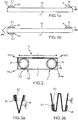
- the temperature sensor 1a comprises a transmitter transducer 3a mounted on the resonant structure 2 and capable of generating waves in the resonant structure over a frequency range comprising at least one resonance frequency of the resonant structure.
- the transmitter transducer 3a comprises two electrodes, an upper electrode receiving a sound signal E1 and a lower electrode receiving a sound signal E2.
- the receiver transducer 4 also comprises two electrodes, an upper electrode providing a signal R corresponding to the acoustic waves picked up by the receiver and a lower electrode connected to the ground or the ground plane formed by the resonant structure when the latter takes the form of a metal plate.
- the temperature sensor 1b comprises two emitting transducers 3a, 3b mounted on the resonant structure 2. These transducers are arranged vis-a-vis on both sides of the resonant structure, at one end thereof. They each comprise an upper electrode and a lower electrode. The two upper electrodes receive a sound signal E1 and E2, respectively. The lower electrodes are connected to the ground, possibly constituted by the metal plate. The receiver transducer 4 is found at the other end of the resonant structure.
- This embodiment has the advantage of making it possible to better select the mode Ao, in particular for plastics, and to double the amplitude of the elastic waves generated in the resonant structure 2.
- the resonant structure may be folded back on itself to multiply its length relative to a planar configuration, while reducing the bulk.
- the Figures 3a and 3b illustrate in this regard a resonant structure in the form of a V-shaped and W-folded plate, respectively, for multiplying the length of the plate by two and four, respectively.
- the path traveled by the acoustic waves is thus increased, thereby improving the sensitivity of the temperature sensor according to the invention.
- the plate is 50 mm long by 7 mm wide, and is folded at 2. It is folded in the middle with a radius of curvature of 3 to 5 mm approximately 5 to 10 mm. times larger than the thickness of the plate.
- the interior space is then sufficient to house a 4-point female jack socket suspended whose usefulness will be detailed below.
- the piezoelectric transducers have a diameter that does not exceed 2 mm.
- This has the disadvantage of reducing the amplitude of the reception signal by decreasing the input / output insertion efficiency at low load impedance (i.e., the ability of the receiver to produce a voltage when charged by a low value resistance of the order of one kilo Ohm).
- the reduction of the length of the resonator must be associated with a reduction in the thickness of the metal sheet to continue working at a constant frequency around 20 kHz.
- the transducers may be advantageous to arrange the transducers at points of focus of the vibratory stress, for example at the focal points of an elliptical resonator.
- the ceramics may be preferable to have the ceramics not on the resonant structure, but under it. The ceramics are then arranged directly on the printed circuit board used as a support, the resonant structure being arranged on the ceramics.
- An exemplary embodiment is as follows. On the printed circuit board side, a solder mask with a varnish is created so that the solder covers only a small part of the surface of the ceramic, for example the equivalent of a pellet of diameter 0.1. at 0.5 mm. At the time of reflow, the PZT pellets float on a solder bed about 0.1 mm high. The other side of the ceramics is also coated with solder paste and the resonant plate is finally placed and suspended on the two pellets PZT. The whole is then passed into a reflow oven. A weld spot connecting the resonant plate to ground is then created. This can be done from two manners. In the first case, the ceramic has a return of silvering.
- the advantage of this configuration is to limit the acoustic losses, the cost of labor, as well as the space between the resonant plate and the surface of the printed circuit board, typically 0.2 mm, that is the equivalent of the thickness of the ceramic.
- the total thickness of the sensor is reduced, which improves its use as a film sensor and reduces the risk of damage in case of violent impact (collapse of the sensor).
- the bending of the resonant plate sees its limited travel either by the printed circuit board or by the protective enclosure.
- the glass-epoxy type printed circuit board can be replaced by a thin Kapton® film, for example 75 ⁇ m.
- the ceramics have no return silvering, so it is necessary to connect the internal faces of ceramics (those against the resonant plate) to the mass. This can be achieved with a single point of solder connecting the resonator to a chip of the printed circuit board.
- the invention more particularly proposes a temperature sensor by an acoustic method directly exploiting the audio port of an electronic unit external to the temperature sensor and programmed to supply acoustic signals to the at least one acoustic wave transmitter and to collect the acoustic signal picked up by the acoustic wave receiver.
- the external electronic unit is typically a microcomputer, a tablet, a smartphone ( smartphone ) and the audio port is a jack, most often female, four-point contact.
- the temperature sensor comprises connection elements for connecting the at least one transmitter and the receiver to the external electronic unit to the temperature sensor.
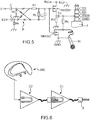
- connection elements comprise a jack with four contact points, typically a plug as shown in particular on the figure 5 .
- the four contact points of the plug F consist of a first and a second contact point E1, E2 intended to convey a stereophonic sound signal, a third contact point GND intended to provide a ground reference and a fourth point of contact Micro for conveying a signal from a microphone, said connector elements being configured to connect the at least one a transmitter at the first and second contact points and for connecting the receiver to the fourth point of contact.
- the stereophonic sound signal is broken down into a left channel found on the first point of contact and a right channel that is found on the second point of contact, these channels making it possible to apply the acoustic signals E1 and E2 at least one transmitter of the temperature sensor.
- the at least one transmitter uses the signals usually sent on a stereo headset, such as that of a freehand audio kit with integrated microphone (headset), to vibrate the resonant structure.
- the acoustic signal picked up by the receiver is then reassembled to the external electronic unit by using the signal usually returned by a microphone, such as the microphone of a free-standing audio kit with integrated microphone.
- the resonance frequencies of the resonant structure are then selected taking into account the limitations of the electronic components dedicated to the audio of the external electronic unit.
- the audio components of a smartphone allow sampling rates of 48 kHz or 96 kHz.
- High-end versions easily go up to 192 kHz. Scanning is done on 16 or 24 quantization bits. It is therefore simultaneously limited in bandwidth, which requires the resonant frequencies to remain typically below 20 kHz (in audible band).
- the power consumption of the sensor does not exceed the milliampere continuously.
- the use of small piezoelectric ceramics whose total intrinsic capacitance is of the order of 5nF limits the need for peak current at 0.6 mA at 20 kHz per Volt of applied voltage. Knowing that the output voltage at the terminals of the headphones of a smartphone or a PC rarely exceeds 3 Vpeak, we deduce that the maximum power requirement is close to 1.2 mArms at 20 kHz (and much less by measure intermittent).
- Two load resistors may be provided to prevent pyroelectric and electrostatic impacts that could damage the operational amplifiers when inserting the jack from the sensor into the socket female of the external electronic unit.
- resistors of high values between 100 kOhms and 10 MOhms are suitable.
- a resistance of at least 1.4 kOhm can be provided for the electronics unit to recognize the presence of an external microphone.
- a high impedance or infinite is recognized as an external microphone while a low impedance less than 1k or a short circuit activates the internal microphone of the electronic unit because it assumes that we connected a 3-point headset or mute (mute) using a 50 Ohm shunt resistor.
- the amplitude of the output signal R (t) thus remains low just before the series resonance while the parallel resonance following the series resonance is masked by the fact that the load impedance is much smaller than the associated equivalent electrical impedance. to the sensor in the case of a parallel resonance. No voltage associated with parallel resonance can thus be detected. Only the series resonance for which the piezoelectric source behaves as a current source is thus well detected. This configuration is also favorable to a well symmetrical resonance peak and increased linearity.
- the connector elements may also include a cord for connecting the at least one transmitter and the receiver to the jack.
- Teflon FEP materials may be preferred to ensure the electrical isolation of the internal channels while a flexible silicone coating may be preferred for the outer sheath. This coating is preferably sufficiently thick to ensure, on the one hand, overall a circular section of the small diameter bead (for example 2.5 mm), aesthetically preferable and avoiding entanglement of the bead, on the other hand, to allow sealing by pinching / partial crushing of the bead at the entrance of the bead. a housing housing the resonant plate. Both materials offer operating temperatures up to 260 ° C peak. Teflon FEP can also be extruded, unlike Teflon PTFE.
- the cord is also advantageously constituted by two coaxial cables, one assigned to transport the transmission signals E1 and E2, the other to the reception of the microphone signal.
- the core of the coaxial receive cable is connected to the receive signal R (t) while the braid is connected to ground. This avoids the capacitive coupling between the input and the output on the very long cords.
- Connector elements may also include a parallel multi-jack splitter acting as a splitter.
- this feature can be exploited to detect a malfunction related to a wiring problem.
- the reception signal R (t) passes through the core of the coaxial cable while the braid constitutes the mass, then there is good input-output isolation: the reception signal is purely piezoelectric and representative of the series resonance.
- the reception signal is connected to the braid while the core constitutes the mass, capacitive coupling occurs between the transmit and receive transducers which is superimposed on the piezoelectric signal.
- the phase of the piezoelectric signal changes strongly so that interference between the capacitive signal and the piezoelectric signal generates a minimum and maximum amplitude around the resonant frequency.
- the presence of resonance and antiresonance at The vicinity of the nominal frequency is then characteristic of parasitic capacitive coupling.
- the external electronic unit is configured to, during a temperature measurement, transmit signals E1 and E2 in phase opposition so as to increase the signal generated in the resonant structure.
- This embodiment also has the advantage of limiting nuisances in telephone conversation mode because the acoustic signals E1, E2 can then be emitted in phase which neutralizes the emission of waves in the resonant structure.
- the external electronic unit is configured to determine the temperature of the resonant structure from the signals from the receiver via the fourth contact point and the microphone input of the audio port of the external electronic unit.
- the temperature sensor includes a microcontroller programmed to determine the temperature of the resonant structure.
- the temperature information thus determined can be communicated to the external electronic unit via the fourth point of contact.
- the microcontroller may use known means for measuring temperature, for example using thermistors or sensors integrated in the microcontroller.
- the microcontroller can itself generate electrical signals to resonate the resonant structure and then quantify the resonant frequency of the structure.
- the potential difference of the stereo signals E1 and E2 can be rectified by a voltage rectifier bridge followed by a tank capacitor and a voltage regulator supplying voltage to the low power and low voltage microcontroller.
- the microcontroller determines the temperature when it is turned on and transmits it to the external electronic unit, via the fourth contact point of the temperature sensor, by PWM ( Pulse Width Modulation ) frequency modulation with filtering. lowpass.
- PWM Pulse Width Modulation
- the signals E1 and E2 are no longer used to excite the elastic waves in the resonant structure, but simply serve to construct a supply voltage source for the microcontroller.
- This method has the advantage of making the temperature sensor fully compatible with the simultaneous use of a hands-free kit in musical listening mode.
- the measurement can only be activated when the excitation frequency is above the cut-off frequency of a high-pass filter arranged at the input of the voltage rectifier bridge.
- the cut-off frequency is chosen above a threshold (for example at 15 kHz) from which it is known that the signals E1 and E2 do not correspond to music signals, this to avoid any activation of the temperature measurement. by music.
- the measurement of the temperature carried out using the at least one transmitter excited by signals usually sent on a stereo headset and the receiver returning a temperature information to the microphone input of an audio port is as follows.
- the temperature measurement is done by emitting a frequency modulated pulse, sinusoidal or square, typically covering the range 5 kHz to 20 kHz, and preferably the range of variation of the highest resonance peak allowed by the sampling frequency audio components of the external electronic unit over the intended operating temperature range.
- the emitted signals E1 and E2 contain two periods of time where the signal is zero, before and after the pulse. This allows on the one hand to overcome synchronization issues. Indeed, most operating systems can handle processes and respond to interrupt requests with latency that may require several tens of milliseconds.
- the signal E1 When the signal E1 is transmitted, it must be certain that the digitization of the signal R at the sampling frequency Fe has begun. Since we are not sure of the exact start time of scanning, we expect a period of security well beyond the operating time of the operating system. It is then known that the acquisition of the signal R is known to a near translation in time. However, the Fourier transform of a delayed signal R introduces only a phase shift in the frequency space, but does not change the spectrum into a module. Thus, working in the frequency space has the advantage of making it possible to overcome any synchronization signal.
- a second interest is a reduction of the side lobes of the rectangular window of the Fourier transform (which can be weighted by a Hamming window).
- the scanning is such that the energy spectral density of the excitation signal is relatively stable, without fluctuating more than 50% of its average value over the entire range of variation of the resonance frequency of the plate. In such a way, it is ensured that whatever the temperature, sufficient signal is available across the receiver to enable the resonance peak shift to be determined with respect to a reference peak identified at a reference temperature TRef1.
- the piezoelectric conversion efficiency is sufficient for the emission signals E1 and E2 of amplitude 2 Vpp applied across the emitting transducers to generate a reception signal R of sufficient amplitude, comparable to that of a microphonic signal.
- the audio pulse typically lasts between 10 ms and 10 seconds depending on the frequency resolution and therefore the desired temperature.
- the sampling of the reception signal on the microphone input can start synchronously or asynchronously.
- the acquisition length is set to begin well before transmission and continues well after the arrival of the reception signal.
- a "zero padding" signal processing is carried out, that is to say adding zero value samples before and after the arrival time of the reception signal to increase the frequency resolution of the acquisition signal which is analyzed by discrete Fourier transform.
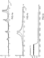
- the acquisition length is therefore typically at least 1 second. In the example given on the Figures 4a-4c , the acquisition is done in 5 seconds, the frequency resolution is 0.2 Hz and the temperature resolution of a few hundredths of a degree Celsius.
- the reception signal does not saturate the input of an analog-digital converter. If necessary, the gain of the microphone is reduced and the average energy of the signal is calculated from the modulus of the spectral components of its Fourier transform in the working frequency band. This makes it possible to identify a possible malfunction of the sensor in case of too low a value.
- the higher amplitude spectral component is used to normalize the spectrum of the receive signal over the range of variability of the resonant frequency. But one can also normalize the spectrum with respect to the peak which one monitors the frequency shift as a function of the temperature. We can choose to take a lower frequency peak if we want to focus on the measurement range to the temperature resolution.
- Tref1 can also be taken at 0 ° C and Tref2 at 37 ° C.
- the offset between the normalized resonance peaks is quantified by calculating the cross-correlation function of the resonance peaks at the two reference temperatures.
- the frequency offset is proportional to the working frequency as well as to the temperature difference and to the coefficient of variation in temperature of the antisymmetric waves propagating in the material constituting the plate (which the it is possible to estimate a little less than -0.1% / ° C, but which depends on one material to another).
- three reference temperatures are taken, for example -15 ° C., 20 ° C. and 50 ° C., and a quadratic variation law of the frequency shift is interpolated. Then an unknown temperature is determined by calculating the offset at the temperature Ti with respect to a reference temperature and applying the quadratic correspondence law for this offset.
- the calibration of the sensor requires knowing two parameters, on the one hand the resonant frequency of the resonant plate at a nominal temperature, on the other hand the coefficient of frequency shift per degree Celsius (approximately 0.04 ° C / 0, 2 Hz for brass).
- the nominal frequency may fluctuate slightly depending on the positioning accuracy of the sensors (positioning typically within 50 ⁇ m), the thickness of glue or solder and the size of the solder pads.
- a 0.2 Hz bias on the nominal frequency results in a calibration error of 0.04 ° C.
- the manufacturing conditions generate a nominal frequency accurate to 0.1%, ie 18 Hz for a nominal frequency of 18 kHz
- the sensors are then produced with an error on the nominal frequency representing an error of +/- 2 ° vs.
- the nominal frequency of the sensor may tend to decrease with aging due to the oxidation of the resonant plate and dust deposited therein reducing its apparent rigidity.
- the enclosure may furthermore be coated with a silicone coating having a low-pass filtering effect of the passive excitation spectrum generated by any mechanical shock or vibration (such as rough friction on hard or textured surfaces).
- the figure 4c represents as for that an example of temperature measurement carried out using the sensor according to the invention inserted into a cooler reversible heating-cooling.
- the cooler first operates a heating regulation between 47 ° C and 51 ° C, before switching to a cooling mode.
- the figure 4b reveals a widening of the resonance peak with temperature rise (curve in solid lines (hot) compared to the curve in dashed lines (cold)). Calculation of a precise offset requires that this expansion remains symmetrical with respect to the central frequency. Enlargement is also accompanied by a subsidence of the resonance and the appearance of distortion peaks reflecting the emission spectrum. The measurement can then lose linearity due to the appearance of local nonlinearities over small temperature ranges, even if overall the slope remains linear. Thus, for some commercial epoxy glues, the measurement can become difficult to exploit beyond 80 ° C.
- the width of the peak is constant with the temperature and therefore that the rigidity of the bonding ensured over the entire temperature range. This condition is fairly well respected with a metal solder, while it can fluctuate from one polymer adhesive to another, especially depending on the glass transition temperature Tg of the adhesive.
- the maximum operating temperature corresponds to either the melting point of the weld (eutectic tin - silver at 217 ° C and commonly with other alloys up to 260 ° C), or at the Curie temperature of PZT ceramic (for example around 330 ° C for some commercial PZT ceramics).
- adhesives are preferably used whose rigidity remains good at high temperatures.
- the critical parameter of the polymer glues is the glass transition temperature Tg. High Tg are found in polyimide glues or some epoxy glues.
- the resonance peak may be noisy by secondary distortion peaks that do not shift with the temperature. These secondary peaks reflect the content of the excitation spectrum and not at all that of the mechanical resonances.
- the excitation is a frequency modulated pulse
- the signal E (f) is not perfectly flat but homeled.
- H (f 0 ) is weighted by the excitation spectrum E (f). If the resonance is spread over a few tens of Hertz, the irregularities of the excitation spectrum are found directly in the output spectrum R (f).
- the module of the output spectrum R (f) can be normalized by the modulus of the excitation spectrum E (f).
- the two time signals (excitation and reception) are digitized with the same number of samples so that they share the same frequency components .
- FFT Fast Fourier Transform
- the transmission part it is not necessarily necessary to transmit a signal of equal duration to the acquisition signal (for example during the 5 seconds of reception).
- an excitation signal can be emitted comprising the desired burst between the frequencies Fmin and Fmax for 3 seconds, then mathematically completing the signal by making "zero padding" up to 5 seconds to complete and equalize the number of samples of the reception signal.
- the temperature sensor is itself equipped with an audio port, typically a female jack with four contact points, on which can be connected a stereo headset or a headset.
- the temperature sensor can be integrated in a stereo headset or in a headset, being for example grouped in the same box with the microphone of a headset.
- the two devices are electrically connected in parallel, it is ie the earphones of the headphones with the at least one transmitter and the receiver R with the microphone.
- the measurement of the temperature is practically transparent for the user when listening to music. Indeed, the resonant frequency of the plate is chosen in the upper part of the audible band, or even in the ultrasound band when the audio components of the external electronic unit allows it.
- the temperature measurement signal E1, E2 is therefore hardly noticeable. It can also be superimposed on the musical signal to be no longer noticeable, although in practice, it is preferable to separate the temperature measurement signal from the musical signal, so make them exclusive to each other to avoid introducing distortion (knowing that the frequency fluctuations are very low, a few ppm per hundredth of a degree Celsius).
- the choice of a transparent measurement or not can be proposed in parameterization to the user according to the desired measurement frequency and temperature resolution.
- the desired temperature resolution can be parameterized according to a so-called fixed mode with a resolution value setting the acquisition length and a measurement interval or according to another so-called adaptive mode if it is anticipated that the working environment undergoes thermal shocks.
- the acquisition length and the measurement interval are variable.
- the length is deliberately short initially, for example 0.1 seconds so as to favor the dynamics and allow as quickly as possible an estimate of the temperature to 1 ° C.
- the temperature variation remains lower than a certain threshold, for example 2 ° C between two successive measurements, the length of the acquisition window is lengthened to a limit value defined by another threshold and the measurement interval (which is always greater than or equal to the acquisition length) so as to refine the temperature measurement.
- the interval between two temperature measurements is automatically reduced so that the measurement interval is as close as possible to the acquisition length for the resolution in progress. If then the difference between two successive measurements remains greater than the current resolution, then the acquisition length and therefore the resolution are automatically decreased in steps until the temperature difference between two successive measurements less than a multiple of the current resolution.
- the temperature sensor includes a module for selecting the "temperature measurement” function or the "using the headset” function.
- This module includes a short-circuiting circuit of the microphone of the headset, depending on the nature of the signals E1 and E2 from the first and the second point of contact, for short-circuiting the microphone the microphone during a temperature measurement and to disconnect the receiver in the absence of temperature measurement.
- This circuit may comprise a high-pass filter having for example a cut-off frequency around 15 kHz and composed of the capacitor C and the resistor Rh.
- the high-pass filter is followed by a rectifier diode bridge P of the stereo signals. E1 and E2 from the first and second point of contact.
- the rectifier bridge P is followed by a stage comprising a resistor bridge R1 (low) and R2 (large) to ensure a fast charge and a slow discharge of a reservoir capacitor C R downstream of the resistor bridge.
- tank capacity C R for biasing the gate of a first NMOS1 transistor and a second NMOS2 transistor.
- Resistor R1 limits the charging current of the tank capacity C R to a few milliamperes and is typically 1 kOhm, while the reservoir capacity C R is typically 1 ⁇ F. The charging time at 95% is then around 30 ms. Resistor R2 conditions the discharge time of the reservoir capacitor C R and therefore the opening time of the transistors and is typically 1 to 10 MOhms, for an opening time of the order of one second.
- the differential is sufficient to turn on the NMOS1 and NMOS2 transistors.
- the first NMOS1 transistor By becoming on, the first NMOS1 transistor connects the receiver of the temperature sensor which delivers the signal R at the fourth point of contact "Micro" and from there to the microphone input of the PC or smartphone.
- a decoupling capacitor Cc is provided on the source side of the first NMOS1 transistor to prevent its source voltage from being comparable to the gate voltage which would prevent the first NMOS1 transistor from becoming on.
- the same gate voltage is used to switch to ground the second NMOS2 transistor connected to the load impedance of the microphone Mi. Downstream of the second transistor NMOS2, we find a series resistor Rs connecting the microphone Mi to the fourth point of contact.
- the microphone Mi is still normally connected via the series resistor Rs (about 1 kOHM) while the receiver R is loaded by a high electrical impedance and is therefore not connected.
- the stereo signals E1 and E2 are in phase opposition.
- the first NMOS1 transistor is on because its threshold voltage is low and typically less than 2V, which connects the receiver R to the fourth contact point, while the second NMOS2 transistor associated with the microphone Mi is short-circuited to ground.
- the receiver R is then charged by the series resistor Rs which has one of its terminals connected to ground.
- the microphone Mi is thus inactive. This situation is favorable because there is no telephone conversation and the temperature measurement operation only lasts a few hundred milliseconds.
- the stereo emission with E1 and E2 in phase opposition ceases and the gate voltage of the NMOS transistors 1 and NMOS2 drops, which reconnects the microphone Mi and disconnects the receiver R.
- the phase difference between the right and left channel signals is arbitrary.
- the probability that the signals are in phase opposition is not zero and it is possible that the microphone Mi is inactivated. But it's not embarrassing because it does not serve then.
- the operating system of the smartphone or the PC When taking a telephone conversation, the operating system of the smartphone or the PC is informed of a possible process of temperature measurement In progress. He can regain control and give priority to the phone mode.
- the deactivation of the temperature sensor lasts at most 1 second, corresponding to the discharge time of the gate voltages of the NMOS1 and NMOS2 transistors.
- the headphone signals are emitted in phase. It is therefore very unlikely that the acoustic signals of a telephone conversation will contain opposite electrical phases for a time sufficient to activate NMOS transistors 1 and NMOS2 and to deactivate the microphone, which would constitute a malfunction.
- temperature sensors can be connected electrically in parallel and physically in a daisy chain. As shown on the figure 6 instead of connecting a MC headset, you can actually put the sensors C1, C2 one behind the other.
- Each sensor may be associated with a resonant structure having a characteristic characteristic frequency. For example, one can choose to play on the length and thickness of a plate so that its frequency is different from the next sensor plate, for example spaced 500 Hz from the next plate.
- a two-group system of N sensors can also be formed.
- the two groups share the same frequency ranges, but the sensors of the first group are fed only with the Right signal E1 (t) and the sensors of the second group are fed with the Left signal E2 (t).
- the sensors may be slightly different from each other with respect to the thickness and / or length of the resonant plate so that each is identifiable over its own wide working frequency range of 500 Hz at 2kHz and corresponding to the expected offset range over the desired working temperature range.
- the measurement is simultaneous for all the sensors of the same group. There is only one reception signal R (t) for all sensors connected in parallel.
- the groups are measured sequentially.
- the sensors are identical. One is connected to the Right Earpiece, the other to the Left Earpiece. The inner electrode of each transmitting transducer is grounded. The receiver transducers are connected in parallel and provide the same signal R (t). In this configuration, placing the signals E1 and E2 in phase or in phase opposition does not create any difference in operation.
- the invention also extends to a computer program product comprising code instructions for performing the steps of this method when said program is run on a computer.
- the invention also relates to the external electronic unit to which the temperature sensor can be connected via its four-point contact plug which is connected to a four point contact point of the electronic unit, typically a female jack.
- the electronic unit is configured, when the plug of the electronic unit and the plug of the temperature sensor are connected together, to provide acoustic wave emission signals on the first and second contact point of its socket , collecting an acoustic wave receiving signal on the fourth contact point of its tap and processing the acoustic wave receiving signal to determine the temperature of the resonant structure of the temperature sensor.
Landscapes
- Physics & Mathematics (AREA)
- Acoustics & Sound (AREA)
- General Physics & Mathematics (AREA)
- Measuring And Recording Apparatus For Diagnosis (AREA)
- Measuring Temperature Or Quantity Of Heat (AREA)
Claims (15)
- Temperatursensor (1a, 1b), enthaltend:- eine Resonanzstruktur (2), die dazu bestimmt ist, in Schwingung versetzt zu werden, um mit einer Resonanzfrequenz zu schwingen, die in Abhängigkeit von der Temperatur der Resonanzstruktur variiert;- zumindest einen Schallwellensender (3a, 3b), der an der Resonanzstruktur (2) angebracht und dazu geeignet ist, dieser Schallwellen zu übertragen, um sie zum Schwingen mit der Resonanzfrequenz zu bringen;- einen Schallwellenempfänger (4), der an der Resonanzstruktur angebracht und dazu geeignet ist, Schallwellen zu empfangen, die sich in der hängenden Struktur ausbreiten;- Anschlusselemente, über welche der zumindest eine Sender und der Empfänger mit einer elektronischen Einheit verbunden werden können, die außerhalb des Temperatursensors vorgesehen ist;dadurch gekennzeichnet, dass die Anschlusselemente einen Stecker (F) mit vier Kontaktpunkten enthalten, die aus einem ersten und einem zweiten Kontaktpunkt (E1, E2), die zum Weiterleiten eines stereophonen Tonsignals bestimmt sind, einem dritten Kontaktpunkt (GND), der zum Bereitstellen einer Massereferenz bestimmt ist, und aus einem vierten Kontaktpunkt (Micro) bestehen, der zum Weiterleiten eines Signals eines Mikrophons bestimmt ist, wobei die Anschlusselemente dazu ausgelegt sind, den zumindest einen Sender (3a, 3b) mit dem ersten und dem zweiten Kontaktpunkt (E1, E2) zu verbinden und um den Empfänger mit dem vierten Kontaktpunkt (Micro) zu verbinden.
- Temperatursensor nach Anspruch 1, enthaltend einen mit zwei Elektroden versehenen Sender, wobei die Anschlusselemente dazu ausgelegt sind, die Elektroden des Senders mit dem ersten bzw. dem zweiten Kontaktpunkt zu verbinden.
- Temperatursensor nach Anspruch 1, enthaltend zwei Sender, die jeweils mit zwei Elektroden versehen sind und beiderseits der Resonanzstruktur einander gegenüberliegend angeordnet sind, wobei die Anschlusselemente dazu ausgelegt sind, eine der Elektroden eines Senders mit dem ersten Kontaktpunkt und eine der Elektroden des anderen Senders mit dem zweiten Kontaktpunkt zu verbinden.
- Temperatursensor nach einem der Ansprüche 1 bis 3, wobei der Empfänger mit zwei Elektroden versehen ist, wobei die Anschlusselemente dazu ausgelegt sind, eine der Elektroden des Empfängers mit dem dritten Kontaktpunkt zu verbinden.
- Sensor nach einem der Ansprüche 1 bis 4, wobei die Resonanzstruktur eine rechteckförmige Platte ist.
- Sensor nach Anspruch 1 bis 5, wobei der zumindest eine Sender und der Empfänger durch Verkleben an die Resonanzstruktur angebracht sind.
- Sensor nach Anspruch 1 bis 5, wobei der zumindest eine Sender und der Empfänger piezoelektrische Wandler sind.
- Sensor nach einem der Ansprüche 1 bis 7, ferner enthaltend ein Gehäuse, in dem die Resonanzstruktur aufgehängt ist.
- Sensor nach einem der Ansprüche 1 bis 8, ferner enthaltend eine Klinkensteckbuchse.
- Sensor nach Anspruch 9, ferner enthaltend eine Kurzschlussschaltung, die dazu ausgelegt ist, bei einer Temperaturmessung ein über die Klinkensteckbuchse mit dem Temperatursensor verbundenes Mikrophon kurzzuschließen und bei ausbleibender Temperaturmessung den Empfänger vom vierten Kontaktpunkt abzuschalten.
- Headset mit einem integrierten Sensor nach einem der Ansprüche 1 bis 10.
- Verfahren zur Temperaturmessung mittels eines Temperatursensors nach einem der Ansprüche 1 bis 10, umfassend die nachfolgenden Schritte:- Bereitstellen von Schallwellensendesignalen am ersten und zweiten Kontaktpunkt;- Empfangen eines Schallwellenempfangssignals am vierten Kontaktpunkt;- Verarbeiten des Schallwellenempfangssignals zum Ermitteln einer Temperatur der Resonanzstruktur.
- Verfahren nach Anspruch 12, wobei die am ersten und am zweiten Kontaktpunkt bereitgestellten Schallwellensendesignale gegenphasig sind.
- Computerprogrammprodukt mit Codeanweisungen zum Durchführen der Schritte des Verfahrens nach einem der Ansprüche 12 und 13, wenn das Programm auf einem Computer ausgeführt wird.
- Elektronische Einheit mit einer Steckbuchse mit vier Kontaktpunkten, die aus einem ersten und einem zweiten Kontaktpunkt, die zum Weiterleiten eines stereophonen Tonsignals bestimmt sind, einem dritten Kontaktpunkt, der zum Bereitstellen einer Massereferenz bestimmt ist, und aus einem vierten Kontaktpunkt bestehen, der zum Weiterleiten eines Signals eines Mikrophons bestimmt ist,
dadurch gekennzeichnet, dass sie dazu ausgelegt ist, dann, wenn die Steckbuchse der elektronischen Einheit und der Stecker mit vier Kontaktpunkten des Temperatursensors nach einem der Ansprüche 1 bis 10 miteinander verbunden sind, Schallwellensendesignalen am ersten und zweiten Kontaktpunkt der Steckbuchse bereitzustellen, ein Schallwellenempfangssignal am vierten Kontaktpunkt der Steckbuchse zu empfangen und das Schallwellenempfangssignal zu verarbeiten, um eine Temperatur zu ermitteln.
Applications Claiming Priority (2)
| Application Number | Priority Date | Filing Date | Title |
|---|---|---|---|
| FR1455242A FR3022024B1 (fr) | 2014-06-10 | 2014-06-10 | Capteur de temperature, unite electronique interagissant avec un tel capteur, procede et programme d'ordinateur associes |
| PCT/EP2015/062851 WO2015189217A1 (fr) | 2014-06-10 | 2015-06-09 | Capteur de température, unité électronique interagissant avec un tel capteur, procédé et programme d'ordinateur associés |
Publications (2)
| Publication Number | Publication Date |
|---|---|
| EP3155388A1 EP3155388A1 (de) | 2017-04-19 |
| EP3155388B1 true EP3155388B1 (de) | 2018-04-04 |
Family
ID=51688176
Family Applications (1)
| Application Number | Title | Priority Date | Filing Date |
|---|---|---|---|
| EP15726217.1A Not-in-force EP3155388B1 (de) | 2014-06-10 | 2015-06-09 | Temperatursensor, mit solch einem sensor interagierende elektronische einheit und zugehöriges verfahren und computerprogramm |
Country Status (4)
| Country | Link |
|---|---|
| US (1) | US10126181B2 (de) |
| EP (1) | EP3155388B1 (de) |
| FR (1) | FR3022024B1 (de) |
| WO (1) | WO2015189217A1 (de) |
Families Citing this family (4)
| Publication number | Priority date | Publication date | Assignee | Title |
|---|---|---|---|---|
| DE102019214417A1 (de) * | 2019-09-23 | 2021-03-25 | Aktiebolaget Skf | Verfahren zum Beschichten einer Sensoreinheit und zugehörige Sensoreinheit |
| CN115698654A (zh) * | 2020-06-08 | 2023-02-03 | 日本电产株式会社 | 噪音分析方法、噪音分析程序以及噪音分析装置 |
| FR3148647A1 (fr) | 2023-05-09 | 2024-11-15 | Jean-Pierre Nikolovski | Capteurs de température haute résolution auto calibrés, unité électronique interagissant avec de tels capteurs, procédé et programme d’ordinateur associés |
| CN121573985A (zh) * | 2026-01-27 | 2026-02-27 | 辽宁国瑞新材料有限公司 | 一种提高沥青包覆均匀性的特种石墨生产工艺改进方法 |
Family Cites Families (4)
| Publication number | Priority date | Publication date | Assignee | Title |
|---|---|---|---|---|
| US20050244014A1 (en) | 2004-04-30 | 2005-11-03 | Avaya Technology Corp. | Acoustic-based temperature sensing in telephones |
| FR2980535B1 (fr) * | 2011-09-22 | 2018-03-09 | Commissariat A L'energie Atomique Et Aux Energies Alternatives | Pompe d'injection d'un fluide, et notamment micropompe utilisable pour delivrer une dose determinee |
| DE102011056533A1 (de) * | 2011-12-16 | 2013-06-20 | WaveScape Technologies GmbH | Verfahren zur Messung einer Temperatur oder eines Abstandsmaßes |
| FR2995702B1 (fr) * | 2012-09-14 | 2014-10-03 | Commissariat Energie Atomique | Systeme et procede de detection et de localisation d'au moins un toucher sur une surface tactile d'un objet. |
-
2014
- 2014-06-10 FR FR1455242A patent/FR3022024B1/fr not_active Expired - Fee Related
-
2015
- 2015-06-09 EP EP15726217.1A patent/EP3155388B1/de not_active Not-in-force
- 2015-06-09 US US15/317,430 patent/US10126181B2/en active Active
- 2015-06-09 WO PCT/EP2015/062851 patent/WO2015189217A1/fr not_active Ceased
Also Published As
| Publication number | Publication date |
|---|---|
| FR3022024A1 (fr) | 2015-12-11 |
| FR3022024B1 (fr) | 2016-07-15 |
| US20170122816A1 (en) | 2017-05-04 |
| US10126181B2 (en) | 2018-11-13 |
| WO2015189217A1 (fr) | 2015-12-17 |
| EP3155388A1 (de) | 2017-04-19 |
Similar Documents
| Publication | Publication Date | Title |
|---|---|---|
| EP2895940B1 (de) | System und verfahren zum erfassen mindestens einer berührung auf einer berührungsempfindlichen oberfläche eines objekts | |
| KR102136375B1 (ko) | 통합된 압전 마이크로기계식 초음파 트랜스듀서 픽셀 및 어레이 | |
| JP4264007B2 (ja) | コンデンサセンサ | |
| JP4900066B2 (ja) | 超音波センサの製造方法 | |
| US20200184176A1 (en) | Ultrasound fingerprint detection and related apparatus and methods | |
| WO2015189217A1 (fr) | Capteur de température, unité électronique interagissant avec un tel capteur, procédé et programme d'ordinateur associés | |
| EP1292171A2 (de) | Chip-Mikrofon und Verfahren zu seiner Herstellung | |
| EP2522152A1 (de) | Vorrichtung zur erkennung von schallwellen und system zur ortung von schallwellen | |
| FR2948787A1 (fr) | Dispositif et procede de localisation d'un contact localement deformant sur une surface tactile deformable d'un objet | |
| CN105264545A (zh) | 具有涂布的压电层的超声波接收器 | |
| CH639762A5 (fr) | Transducteur de pression a element vibrant. | |
| US20230121053A1 (en) | Electronic acoustic devices, mems microphones, and equalization methods | |
| EP1031229B1 (de) | Verfahren zur erzeugung von akustischen signalen aus einer speicherkarte oder chipkarte und karte zur durchführung des verfahrens | |
| FR3056978A1 (fr) | Capteur de pression, en particulier microphone a agencement ameliore | |
| CN113115148A (zh) | 一种耳机及入耳检测方法、装置 | |
| WO2013004962A1 (fr) | Dispositif piezoelectrique | |
| CN100579294C (zh) | 可施加smd的定向电容式传声器 | |
| JP2007538435A (ja) | コンデンサマイクロフォン | |
| FR2825882A1 (fr) | Vitrage interactif avec fonctions microphones et haut-parleur | |
| WO2020011699A1 (fr) | Capteur inductif et capacitif, et détecteur équipé d'un tel capteur inductif et capacitif | |
| FR2559984A1 (fr) | Microphone auriculaire de contact | |
| WO2018219822A1 (fr) | Procédé de commande d'un dispositif nomade | |
| FR3148647A1 (fr) | Capteurs de température haute résolution auto calibrés, unité électronique interagissant avec de tels capteurs, procédé et programme d’ordinateur associés | |
| CH709293A2 (fr) | Microphone passif. | |
| FR2848700A1 (fr) | Panneau interactif avec fonctions microphone et haut parleur integres |
Legal Events
| Date | Code | Title | Description |
|---|---|---|---|
| STAA | Information on the status of an ep patent application or granted ep patent |
Free format text: STATUS: THE INTERNATIONAL PUBLICATION HAS BEEN MADE |
|
| PUAI | Public reference made under article 153(3) epc to a published international application that has entered the european phase |
Free format text: ORIGINAL CODE: 0009012 |
|
| STAA | Information on the status of an ep patent application or granted ep patent |
Free format text: STATUS: REQUEST FOR EXAMINATION WAS MADE |
|
| 17P | Request for examination filed |
Effective date: 20161219 |
|
| AK | Designated contracting states |
Kind code of ref document: A1 Designated state(s): AL AT BE BG CH CY CZ DE DK EE ES FI FR GB GR HR HU IE IS IT LI LT LU LV MC MK MT NL NO PL PT RO RS SE SI SK SM TR |
|
| AX | Request for extension of the european patent |
Extension state: BA ME |
|
| DAV | Request for validation of the european patent (deleted) | ||
| DAX | Request for extension of the european patent (deleted) | ||
| GRAP | Despatch of communication of intention to grant a patent |
Free format text: ORIGINAL CODE: EPIDOSNIGR1 |
|
| STAA | Information on the status of an ep patent application or granted ep patent |
Free format text: STATUS: GRANT OF PATENT IS INTENDED |
|
| INTG | Intention to grant announced |
Effective date: 20171011 |
|
| GRAS | Grant fee paid |
Free format text: ORIGINAL CODE: EPIDOSNIGR3 |
|
| GRAA | (expected) grant |
Free format text: ORIGINAL CODE: 0009210 |
|
| STAA | Information on the status of an ep patent application or granted ep patent |
Free format text: STATUS: THE PATENT HAS BEEN GRANTED |
|
| AK | Designated contracting states |
Kind code of ref document: B1 Designated state(s): AL AT BE BG CH CY CZ DE DK EE ES FI FR GB GR HR HU IE IS IT LI LT LU LV MC MK MT NL NO PL PT RO RS SE SI SK SM TR |
|
| REG | Reference to a national code |
Ref country code: GB Ref legal event code: FG4D Free format text: NOT ENGLISH |
|
| REG | Reference to a national code |
Ref country code: CH Ref legal event code: EP |
|
| REG | Reference to a national code |
Ref country code: AT Ref legal event code: REF Ref document number: 986095 Country of ref document: AT Kind code of ref document: T Effective date: 20180415 |
|
| REG | Reference to a national code |
Ref country code: IE Ref legal event code: FG4D Free format text: LANGUAGE OF EP DOCUMENT: FRENCH |
|
| REG | Reference to a national code |
Ref country code: DE Ref legal event code: R096 Ref document number: 602015009609 Country of ref document: DE |
|
| REG | Reference to a national code |
Ref country code: FR Ref legal event code: PLFP Year of fee payment: 4 |
|
| REG | Reference to a national code |
Ref country code: NL Ref legal event code: MP Effective date: 20180404 |
|
| REG | Reference to a national code |
Ref country code: LT Ref legal event code: MG4D |
|
| PG25 | Lapsed in a contracting state [announced via postgrant information from national office to epo] |
Ref country code: NL Free format text: LAPSE BECAUSE OF FAILURE TO SUBMIT A TRANSLATION OF THE DESCRIPTION OR TO PAY THE FEE WITHIN THE PRESCRIBED TIME-LIMIT Effective date: 20180404 |
|
| PG25 | Lapsed in a contracting state [announced via postgrant information from national office to epo] |
Ref country code: NO Free format text: LAPSE BECAUSE OF FAILURE TO SUBMIT A TRANSLATION OF THE DESCRIPTION OR TO PAY THE FEE WITHIN THE PRESCRIBED TIME-LIMIT Effective date: 20180704 Ref country code: FI Free format text: LAPSE BECAUSE OF FAILURE TO SUBMIT A TRANSLATION OF THE DESCRIPTION OR TO PAY THE FEE WITHIN THE PRESCRIBED TIME-LIMIT Effective date: 20180404 Ref country code: BG Free format text: LAPSE BECAUSE OF FAILURE TO SUBMIT A TRANSLATION OF THE DESCRIPTION OR TO PAY THE FEE WITHIN THE PRESCRIBED TIME-LIMIT Effective date: 20180704 Ref country code: ES Free format text: LAPSE BECAUSE OF FAILURE TO SUBMIT A TRANSLATION OF THE DESCRIPTION OR TO PAY THE FEE WITHIN THE PRESCRIBED TIME-LIMIT Effective date: 20180404 Ref country code: AL Free format text: LAPSE BECAUSE OF FAILURE TO SUBMIT A TRANSLATION OF THE DESCRIPTION OR TO PAY THE FEE WITHIN THE PRESCRIBED TIME-LIMIT Effective date: 20180404 Ref country code: SE Free format text: LAPSE BECAUSE OF FAILURE TO SUBMIT A TRANSLATION OF THE DESCRIPTION OR TO PAY THE FEE WITHIN THE PRESCRIBED TIME-LIMIT Effective date: 20180404 Ref country code: LT Free format text: LAPSE BECAUSE OF FAILURE TO SUBMIT A TRANSLATION OF THE DESCRIPTION OR TO PAY THE FEE WITHIN THE PRESCRIBED TIME-LIMIT Effective date: 20180404 Ref country code: PL Free format text: LAPSE BECAUSE OF FAILURE TO SUBMIT A TRANSLATION OF THE DESCRIPTION OR TO PAY THE FEE WITHIN THE PRESCRIBED TIME-LIMIT Effective date: 20180404 |
|
| PG25 | Lapsed in a contracting state [announced via postgrant information from national office to epo] |
Ref country code: LV Free format text: LAPSE BECAUSE OF FAILURE TO SUBMIT A TRANSLATION OF THE DESCRIPTION OR TO PAY THE FEE WITHIN THE PRESCRIBED TIME-LIMIT Effective date: 20180404 Ref country code: HR Free format text: LAPSE BECAUSE OF FAILURE TO SUBMIT A TRANSLATION OF THE DESCRIPTION OR TO PAY THE FEE WITHIN THE PRESCRIBED TIME-LIMIT Effective date: 20180404 Ref country code: GR Free format text: LAPSE BECAUSE OF FAILURE TO SUBMIT A TRANSLATION OF THE DESCRIPTION OR TO PAY THE FEE WITHIN THE PRESCRIBED TIME-LIMIT Effective date: 20180705 Ref country code: RS Free format text: LAPSE BECAUSE OF FAILURE TO SUBMIT A TRANSLATION OF THE DESCRIPTION OR TO PAY THE FEE WITHIN THE PRESCRIBED TIME-LIMIT Effective date: 20180404 |
|
| REG | Reference to a national code |
Ref country code: AT Ref legal event code: MK05 Ref document number: 986095 Country of ref document: AT Kind code of ref document: T Effective date: 20180404 |
|
| PG25 | Lapsed in a contracting state [announced via postgrant information from national office to epo] |
Ref country code: PT Free format text: LAPSE BECAUSE OF FAILURE TO SUBMIT A TRANSLATION OF THE DESCRIPTION OR TO PAY THE FEE WITHIN THE PRESCRIBED TIME-LIMIT Effective date: 20180806 |
|
| REG | Reference to a national code |
Ref country code: DE Ref legal event code: R097 Ref document number: 602015009609 Country of ref document: DE |
|
| PG25 | Lapsed in a contracting state [announced via postgrant information from national office to epo] |
Ref country code: DK Free format text: LAPSE BECAUSE OF FAILURE TO SUBMIT A TRANSLATION OF THE DESCRIPTION OR TO PAY THE FEE WITHIN THE PRESCRIBED TIME-LIMIT Effective date: 20180404 Ref country code: EE Free format text: LAPSE BECAUSE OF FAILURE TO SUBMIT A TRANSLATION OF THE DESCRIPTION OR TO PAY THE FEE WITHIN THE PRESCRIBED TIME-LIMIT Effective date: 20180404 Ref country code: AT Free format text: LAPSE BECAUSE OF FAILURE TO SUBMIT A TRANSLATION OF THE DESCRIPTION OR TO PAY THE FEE WITHIN THE PRESCRIBED TIME-LIMIT Effective date: 20180404 Ref country code: RO Free format text: LAPSE BECAUSE OF FAILURE TO SUBMIT A TRANSLATION OF THE DESCRIPTION OR TO PAY THE FEE WITHIN THE PRESCRIBED TIME-LIMIT Effective date: 20180404 Ref country code: CZ Free format text: LAPSE BECAUSE OF FAILURE TO SUBMIT A TRANSLATION OF THE DESCRIPTION OR TO PAY THE FEE WITHIN THE PRESCRIBED TIME-LIMIT Effective date: 20180404 Ref country code: SK Free format text: LAPSE BECAUSE OF FAILURE TO SUBMIT A TRANSLATION OF THE DESCRIPTION OR TO PAY THE FEE WITHIN THE PRESCRIBED TIME-LIMIT Effective date: 20180404 |
|
| REG | Reference to a national code |
Ref country code: CH Ref legal event code: PL |
|
| PLBE | No opposition filed within time limit |
Free format text: ORIGINAL CODE: 0009261 |
|
| STAA | Information on the status of an ep patent application or granted ep patent |
Free format text: STATUS: NO OPPOSITION FILED WITHIN TIME LIMIT |
|
| PG25 | Lapsed in a contracting state [announced via postgrant information from national office to epo] |
Ref country code: SM Free format text: LAPSE BECAUSE OF FAILURE TO SUBMIT A TRANSLATION OF THE DESCRIPTION OR TO PAY THE FEE WITHIN THE PRESCRIBED TIME-LIMIT Effective date: 20180404 Ref country code: IT Free format text: LAPSE BECAUSE OF FAILURE TO SUBMIT A TRANSLATION OF THE DESCRIPTION OR TO PAY THE FEE WITHIN THE PRESCRIBED TIME-LIMIT Effective date: 20180404 |
|
| REG | Reference to a national code |
Ref country code: BE Ref legal event code: MM Effective date: 20180630 |
|
| 26N | No opposition filed |
Effective date: 20190107 |
|
| REG | Reference to a national code |
Ref country code: IE Ref legal event code: MM4A |
|
| PG25 | Lapsed in a contracting state [announced via postgrant information from national office to epo] |
Ref country code: MC Free format text: LAPSE BECAUSE OF FAILURE TO SUBMIT A TRANSLATION OF THE DESCRIPTION OR TO PAY THE FEE WITHIN THE PRESCRIBED TIME-LIMIT Effective date: 20180404 Ref country code: LU Free format text: LAPSE BECAUSE OF NON-PAYMENT OF DUE FEES Effective date: 20180609 |
|
| PG25 | Lapsed in a contracting state [announced via postgrant information from national office to epo] |
Ref country code: IE Free format text: LAPSE BECAUSE OF NON-PAYMENT OF DUE FEES Effective date: 20180609 Ref country code: LI Free format text: LAPSE BECAUSE OF NON-PAYMENT OF DUE FEES Effective date: 20180630 Ref country code: CH Free format text: LAPSE BECAUSE OF NON-PAYMENT OF DUE FEES Effective date: 20180630 |
|
| PG25 | Lapsed in a contracting state [announced via postgrant information from national office to epo] |
Ref country code: SI Free format text: LAPSE BECAUSE OF FAILURE TO SUBMIT A TRANSLATION OF THE DESCRIPTION OR TO PAY THE FEE WITHIN THE PRESCRIBED TIME-LIMIT Effective date: 20180404 Ref country code: BE Free format text: LAPSE BECAUSE OF NON-PAYMENT OF DUE FEES Effective date: 20180630 |
|
| PG25 | Lapsed in a contracting state [announced via postgrant information from national office to epo] |
Ref country code: MT Free format text: LAPSE BECAUSE OF FAILURE TO SUBMIT A TRANSLATION OF THE DESCRIPTION OR TO PAY THE FEE WITHIN THE PRESCRIBED TIME-LIMIT Effective date: 20180404 |
|
| PG25 | Lapsed in a contracting state [announced via postgrant information from national office to epo] |
Ref country code: TR Free format text: LAPSE BECAUSE OF FAILURE TO SUBMIT A TRANSLATION OF THE DESCRIPTION OR TO PAY THE FEE WITHIN THE PRESCRIBED TIME-LIMIT Effective date: 20180404 |
|
| PG25 | Lapsed in a contracting state [announced via postgrant information from national office to epo] |
Ref country code: HU Free format text: LAPSE BECAUSE OF FAILURE TO SUBMIT A TRANSLATION OF THE DESCRIPTION OR TO PAY THE FEE WITHIN THE PRESCRIBED TIME-LIMIT; INVALID AB INITIO Effective date: 20150609 Ref country code: CY Free format text: LAPSE BECAUSE OF FAILURE TO SUBMIT A TRANSLATION OF THE DESCRIPTION OR TO PAY THE FEE WITHIN THE PRESCRIBED TIME-LIMIT Effective date: 20180404 Ref country code: MK Free format text: LAPSE BECAUSE OF NON-PAYMENT OF DUE FEES Effective date: 20180404 |
|
| PG25 | Lapsed in a contracting state [announced via postgrant information from national office to epo] |
Ref country code: IS Free format text: LAPSE BECAUSE OF FAILURE TO SUBMIT A TRANSLATION OF THE DESCRIPTION OR TO PAY THE FEE WITHIN THE PRESCRIBED TIME-LIMIT Effective date: 20180804 |
|
| PGFP | Annual fee paid to national office [announced via postgrant information from national office to epo] |
Ref country code: FR Payment date: 20230623 Year of fee payment: 9 Ref country code: DE Payment date: 20230620 Year of fee payment: 9 |
|
| PGFP | Annual fee paid to national office [announced via postgrant information from national office to epo] |
Ref country code: GB Payment date: 20230622 Year of fee payment: 9 |
|
| REG | Reference to a national code |
Ref country code: DE Ref legal event code: R119 Ref document number: 602015009609 Country of ref document: DE |
|
| GBPC | Gb: european patent ceased through non-payment of renewal fee |
Effective date: 20240609 |
|
| PG25 | Lapsed in a contracting state [announced via postgrant information from national office to epo] |
Ref country code: DE Free format text: LAPSE BECAUSE OF NON-PAYMENT OF DUE FEES Effective date: 20250101 |
|
| PG25 | Lapsed in a contracting state [announced via postgrant information from national office to epo] |
Ref country code: FR Free format text: LAPSE BECAUSE OF NON-PAYMENT OF DUE FEES Effective date: 20240630 |
|
| PG25 | Lapsed in a contracting state [announced via postgrant information from national office to epo] |
Ref country code: GB Free format text: LAPSE BECAUSE OF NON-PAYMENT OF DUE FEES Effective date: 20240609 |