EP3155505B1 - Dispositif de maintien de surface tactile - Google Patents
Dispositif de maintien de surface tactile Download PDFInfo
- Publication number
- EP3155505B1 EP3155505B1 EP15727969.6A EP15727969A EP3155505B1 EP 3155505 B1 EP3155505 B1 EP 3155505B1 EP 15727969 A EP15727969 A EP 15727969A EP 3155505 B1 EP3155505 B1 EP 3155505B1
- Authority
- EP
- European Patent Office
- Prior art keywords
- frame
- capacitive
- touch
- deformable
- plate
- Prior art date
- Legal status (The legal status is an assumption and is not a legal conclusion. Google has not performed a legal analysis and makes no representation as to the accuracy of the status listed.)
- Not-in-force
Links
Images




Classifications
-
- G—PHYSICS
- G06—COMPUTING OR CALCULATING; COUNTING
- G06F—ELECTRIC DIGITAL DATA PROCESSING
- G06F1/00—Details not covered by groups G06F3/00 - G06F13/00 and G06F21/00
- G06F1/16—Constructional details or arrangements
- G06F1/1601—Constructional details related to the housing of computer displays, e.g. of CRT monitors, of flat displays
-
- G—PHYSICS
- G06—COMPUTING OR CALCULATING; COUNTING
- G06F—ELECTRIC DIGITAL DATA PROCESSING
- G06F3/00—Input arrangements for transferring data to be processed into a form capable of being handled by the computer; Output arrangements for transferring data from processing unit to output unit, e.g. interface arrangements
- G06F3/01—Input arrangements or combined input and output arrangements for interaction between user and computer
- G06F3/03—Arrangements for converting the position or the displacement of a member into a coded form
- G06F3/041—Digitisers, e.g. for touch screens or touch pads, characterised by the transducing means
- G06F3/044—Digitisers, e.g. for touch screens or touch pads, characterised by the transducing means by capacitive means
- G06F3/0447—Position sensing using the local deformation of sensor cells
-
- H—ELECTRICITY
- H03—ELECTRONIC CIRCUITRY
- H03K—PULSE TECHNIQUE
- H03K17/00—Electronic switching or gating, i.e. not by contact-making and –breaking
- H03K17/94—Electronic switching or gating, i.e. not by contact-making and –breaking characterised by the way in which the control signals are generated
- H03K17/96—Touch switches
- H03K17/962—Capacitive touch switches
-
- H—ELECTRICITY
- H03—ELECTRONIC CIRCUITRY
- H03K—PULSE TECHNIQUE
- H03K17/00—Electronic switching or gating, i.e. not by contact-making and –breaking
- H03K17/94—Electronic switching or gating, i.e. not by contact-making and –breaking characterised by the way in which the control signals are generated
- H03K17/965—Switches controlled by moving an element forming part of the switch
- H03K17/975—Switches controlled by moving an element forming part of the switch using a capacitive movable element
-
- H—ELECTRICITY
- H03—ELECTRONIC CIRCUITRY
- H03K—PULSE TECHNIQUE
- H03K2217/00—Indexing scheme related to electronic switching or gating, i.e. not by contact-making or -breaking covered by H03K17/00
- H03K2217/94—Indexing scheme related to electronic switching or gating, i.e. not by contact-making or -breaking covered by H03K17/00 characterised by the way in which the control signal is generated
- H03K2217/96—Touch switches
- H03K2217/9607—Capacitive touch switches
- H03K2217/960755—Constructional details of capacitive touch and proximity switches
Definitions
- the invention is in the field of tactile surfaces and more particularly relates to a device for maintaining such a surface.
- the known solutions are mainly the deployment of a capacitive film on the surface, the installation of an infrared frame on the surface or the measurement of effort from strain gauges or pressure sensors.
- the patent US 3,657,475 describes four sensors interposed between a fixed support and a tactile surface at the four corners of the latter. These sensors are strain gages or piezoelectric sensors. They must, on the one hand, support the empty weight of the touch surface and, on the other hand, remain sensitive to touches whose strength or pressure is added to the weight of this touch surface. The force of the touch can not be too weak compared to the weight of the surface so as not to induce problems of sensitivity as well as precision. In addition, the sensors used in this document are quite expensive and the piezoelectric sensors in particular are sensitive to temperature variations.
- Another device described in the application EP0497398 A2 makes it possible to maintain a vertical or horizontal plate by suspension means on the upper part of the plate and elastic elements on the lower part. Since the purpose of the holding device is only to relieve the weight of the plate, strain gauges connected to mounting elements then make it possible to measure the forces generated by the interaction.
- the aforementioned patent US7109976 discloses a display screen attachment device that includes a base having first and second surfaces, and a portion extending from the second surface.
- the base is configured to be mounted on the screen and positioned between the screen and a structure remaining adjacent to the screen, for example a telescope or frame of the screen. Even though this arrangement avoids that certain foreign bodies pass between the screen and the adjacent structure, dust and liquids can stagnate in the bowl thus formed. Furthermore, a prestressing added to the weight of the surface is applied by an elastic element on the force sensor and changes the operating range of the sensor to the detriment of its sensitivity.
- An object of the present invention is to provide a device for maintaining a large tactile surface, to avoid deformations of the surface.
- the device of the invention allows the maintenance of a surface at several points to increase the apparent rigidity of the surface and prevent its depression during the interaction.
- Another object of the present invention is to propose a modular device for fixing a large tactile surface that is easily the addition or removal of fasteners.
- the device of the invention makes it possible to limit the deformation of the surface to be touched by fixing it on a built-in frame.
- Another object of the present invention is to provide a device for fixing a surface to be tactilized, which offers an easy implementation and a reduced cost of implementation.
- Another object of the invention is to provide a device that combines the functions of maintaining a surface to be touched with those of detecting an interaction on the surface.
- the device of the invention can be coupled to an electronic module in order to perform capacitive measurements, and be associated with an interaction localization method for determining an interaction point on the surface.
- the present invention will advantageously apply to large interactive terminals, furniture to be touched, or any application called "simple touch”.
- the proposed device Due to the low cost of the proposed device, a typical application may be the touching of a large ceiling lamp in the passenger compartment of an automobile.
- the proposed device does not alter the transparency of the ceiling lamp, and is particularly well suited to let light.
- the invention proposes a device according to claim 1.
- Advantageous variants are defined in claims 2-9.
- the Figure 1 shows in side view a block diagram of the holding device of the invention in one embodiment.
- the device of the invention makes it possible to maintain a plate (102) to be touched in a frame (104).
- the frame has an upper flange (104-a) and a lower flange (104-b).
- the plate (102) has an upper face (102-a) and an opposite face (102-b).
- the plate holding device includes a first upper member (106) extending between the upper face (102-a) of the plate and the upper rim (104-a) of the frame.
- the device further comprises a second element lower section (108) extending between the opposite face (102-b) of the plate and the lower edge (104-b) of the frame.
- the lower element is a capacitive component that can detect a displacement of the plate during an interaction with it, such as a simple touch on the surface.
- the capacitive component comprises a first movable electrode integral with the opposite face of the touch surface (102-b) and a second fixed electrode integral with the frame (104-b).
- the holding device of the invention allows a plate to be retained between the upper and lower rims of the frame by an arrangement and a distribution of elastic upper elements and capacitive lower elements. The plate is then pinched by the device that ensures its maintenance.
- the upper element (106) is an elastic element which can be made of different rigid or semi-rigid materials such as for example polymers or foam or a spring to allow sufficient deformation during an interaction on the surface from the plate, and resume their original form of rest.
- the deformable elastic upper member used in the invention may be of different shapes and configurations. In one embodiment as illustrated on the figure 1 , it is of substantially identical shape to the capacitive lower element and is placed opposite the latter (108).
- each elastic upper element can be glued to the frame and the surface to be touched.
- the upper element may have a variable rest thickness that is identical to or different from the thickness of the capacitive lower element.
- the device of the invention may comprise elastic and capacitive elements which are the same or different in number depending on the size or shape of the surface to be touched or according to the invention.
- the elastic means are at least three in number and the capacitive means are at least three in number.
- the ceiling light glass can be retained in a frame by four devices positioned at each corner of the surface.
- the figure 2 shows in side view a variant of implementation of the holding device of the invention wherein the deformable element is composed of a capacitive element.
- the holding device in this variant consists of two capacitive sensors assembled into a unitary capacitive device, said fork sensor.
- the fork sensor comprises a central armature (208-a, 208-b) integral with the surface 202, and two external armatures (210-a, 210-b) integral with the rims of the frame, the external armatures being respectively separated from the central frame by a material dielectric (206-a, 206-b).
- the capacitive sensors are located respectively on either side of the plate 202 having an upper face and a lower face.
- the sensor located above the plate is called 'upper sensor' and the sensor located below the plate is called 'lower sensor'.
- the sensors are arranged on the edges of the plate and embedded in a frame 204.
- each sensor comprises two electrodes separated by a dielectric (206-a, 206-b).
- the upper sensor comprises a first electrode 208-a integral with the plate and a second electrode 210-a secured to the frame.
- a dielectric 206-a consisting of an elastic and insulating material, such as silicone or polyurethane, is located between the two electrodes.
- the dielectric makes it possible to increase the measured capacitance by increasing the permittivity of the medium.
- it is a booster function that compresses when a force related to an interaction is applied to the surface to bring the two electrodes together, and which relaxes when the force disappears in order to return the electrodes to their initial position. .
- the lower sensor comprises a first 208-b electrode integral with the plate and a second 210-b electrode integral with the frame, separated by a dielectric 206-b.
- Each integral electrode of the plate is movable under the effect of pressure on the plate and the deformation of the dielectric.
- Each fixed electrode of the frame is fixed and constitutes a signal electrode which allows the measurement of forces exerted on the surface.
- the holding device of the invention based on fork sensor can be coupled to an interaction detection and localization system such as that described in the applicant's patent application entitled “Method and device for locating an interaction on a surface tactile "filed the same day.
- the figure 3a is a side view which illustrates an exemplary embodiment of the holding device where the deformable upper element (306) is not in direct line with a capacitive element (308).
- the deformable upper element is positioned at regular intervals between two capacitive elements (308, 310).
- a deformable upper element may be arranged to be totally or partially facing a capacitive lower element.
- the deformable upper element may be a capacitive element as described with reference to FIG. figure 2 .
- the figure 3b illustrates an alternative embodiment of the holding device of the invention, wherein a seal (410) is added between the plate (402) and the lower rim of the frame (404) to avoid a bowl appearance that may occur on certain large surfaces.
- the role of the seal is then to seal against dust and liquids in the system.
- It is made of a waterproof material, such as a polymer or a plastic film for example, and is deformable in order to disturb as little as possible the deformation of the capacitive sensors. This is glued on both the frame (404) and the plate (402).
- the deformable upper element (406) may be an elastic element or a capacitive element.
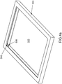
- the Figures 4a and 4b illustrate a frame under a 3D representation, for inserting a large surface (502) to be tactilized.
- the frame is a monolithic or unitary block (504), forming a single piece in which the surface is embedded.
- the surface can be maintained according to the variants described with reference to Figures 1 to 3 either by pair of fork sensors (506, 508) or by upper (506) or lower (508) sensors and deformable elements (510) respectively on the opposite surface side.
- the number of sensors can vary from at least three sensors to a plurality distributed around the perimeter of the frame.
- the number and position of Sensors and deformable fasteners may vary depending on the size and stiffness of the surface.
- the surface is held by four pairs of fork sensors positioned at each corner of the frame.
- the Figure 4c illustrates a variant of monolithic frame having a lateral opening (512) for sliding the surface inside the frame.
- the frame may comprise a removable part (not shown) which can be screwed or glued to the frame after the insertion of the surface to close the frame and provide additional protection.
- the frame is a rigid structure that can be made of different rigid or semi-rigid materials such as for example metals (steel, aluminum, ...) and plastics (ABS, PC, ...) in order to have sufficient strength during an interaction on the surface of the plate.
- fixing modules can be easily added or removed.
- the same surface can be maintained in a frame by modules.
Landscapes
- Engineering & Computer Science (AREA)
- General Engineering & Computer Science (AREA)
- Theoretical Computer Science (AREA)
- Human Computer Interaction (AREA)
- Physics & Mathematics (AREA)
- General Physics & Mathematics (AREA)
- Computer Hardware Design (AREA)
- Switches That Are Operated By Magnetic Or Electric Fields (AREA)
Description
- L'invention est dans le domaine des surfaces tactiles et concerne plus particulièrement un dispositif de maintien d'une telle surface.
- Il existe différentes approches pour rendre tactile une surface de n'importe quelle nature, en permettant de localiser un appui sur la surface. Les solutions connues sont principalement le déploiement d'un film capacitif sur la surface, la pose d'un cadre infrarouge sur la surface ou la mesure d'effort à partir de jauges de contraintes ou de capteurs de pression.
- Le brevet
US 3,657,475 décrit quatre capteurs s'interposant entre un support fixe et une surface tactile aux quatre coins de cette dernière. Ces capteurs sont des jauges de contrainte ou des capteurs piézoélectriques. Ils doivent, d'une part, supporter le poids à vide de la surface tactile et, d'autre part, rester sensibles à des touchers dont la force ou la pression s'ajoute au poids de cette surface tactile. La force du toucher ne peut donc pas être trop faible par rapport au poids de la surface pour ne pas induire des problèmes de sensibilité ainsi que de précision. En outre, les capteurs employés dans ce document sont assez coûteux et les capteurs piézoélectriques en particulier sont sensibles aux variations de température. - Toutes ces solutions sont particulièrement adaptées aux surfaces dites de petite taille en général inférieures à une trentaine de pouces, comme les tablettes par exemple. Cependant, elles deviennent inappropriées pour des surfaces à tactiliser plus importantes comme par exemple des vitres pour des tables ou pour des plafonniers de voiture.
- En effet, le passage à des surfaces plus importantes génère des problèmes liés à la rigidité et donc à la déformation de la surface sous l'application d'une force d'interaction. Même si des solutions satisfaisantes sont proposées pour aborder cet aspect de déformation d'une surface, des inconvénients demeurent dont entre autre celui de la difficulté à avoir un bon maintien de la surface du fait des dimensions plus importantes.
- La plupart des dispositifs existants pour maintenir des surfaces tactiles utilisent généralement un élément élastique permettant de plaquer la surface à rendre tactile contre le capteur de force. Ce dernier se situe alors entre la surface et un bâti. De tels dispositifs sont par exemple décrits dans les brevets
US7109976 ouUS7149571 . - Un autre dispositif décrit dans la demande
EP0497398 A2 , permet de maintenir une plaque verticale ou horizontale par des moyens de suspension sur la partie haute de la plaque et des éléments élastiques sur la partie basse. Le dispositif de maintien n'ayant pour but que de soulager le poids de la plaque, des jauges de contraintes reliées à des éléments de montage permettent ensuite de mesurer les forces engendrées par l'interaction. - Le brevet précité
US7109976 décrit un dispositif d'attachement pour écran d'affichage qui comprend une base ayant des première et seconde surfaces, et une partie s'étendant à partir de la deuxième surface. La base est configurée pour être montée sur l'écran et être positionnée entre l'écran et une structure demeurant adjacente à l'écran, par exemple une lunette ou un cadre de l'écran. Même si cet arrangement évite que certains corps étrangers ne passent entre l'écran et la structure adjacente, des poussières et des liquides peuvent stagner dans la cuvette ainsi formée. Par ailleurs, une précontrainte s'ajoutant au poids de la surface est appliquée par un élément élastique sur le capteur d'effort et vient modifier la plage de fonctionnement du capteur au détriment de sa sensibilité. - Ainsi, il n'existe pas dans l'art antérieur, de solution qui pallie les inconvénients des approches existantes, et qui soit adaptée au maintien d'une surface de grande dimension à tactiliser. La présente invention répond à ce besoin.
- Un objet de la présente invention est de fournir un dispositif pour maintenir une surface tactile de grande taille, afin d'éviter les déformations de la surface.
- Avantageusement, le dispositif de l'invention permet le maintien d'une surface en plusieurs points pour augmenter la rigidité apparente de la surface et éviter son enfoncement lors de l'interaction.
- Un autre objet de la présente invention est de proposer un dispositif modulaire de fixation d'une surface tactile de grande taille permettant facilement l'ajout ou le retrait de modules de fixation.
- Avantageusement, le dispositif de l'invention permet de limiter la déformation de la surface à tactiliser en la fixant sur un bâti encastrable.
- Un autre objet de la présente invention est de fournir un dispositif de fixation d'une surface à tactiliser offrant une mise en oeuvre aisée et un coût d'implémentation réduit.
- Un autre objet de l'invention est de fournir un dispositif qui combine les fonctions de maintien d'une surface à tactiliser à celles de détection d'une interaction sur la surface. Dans un mode de réalisation, le dispositif de l'invention peut être couplé à un module électronique afin d'effectuer des mesures capacitives, et être associé à un procédé de localisation d'interaction permettant de déterminer un point d'interaction sur la surface.
- La présente invention s'appliquera avantageusement pour des bornes interactives de grande taille, des meubles à tactiliser, ou encore toute application dite «simple touché».
- De par le faible coût du dispositif proposé, une application typique pourra être la tactilisation d'un plafonnier de grande taille dans l'habitacle d'une automobile. Avantageusement, le dispositif proposé n'altère pas la transparence du plafonnier, et est particulièrement bien adapté pour laisser passer la lumière.
- Pour obtenir les résultats recherchés, l'invention propose un dispositif selon la revendication 1. Des variantes avantageuses sont définies dans les revendications 2-9.
- Différents aspects et avantages de l'invention vont apparaitre en appui de la description d'un mode préféré d'implémentation de l'invention mais non limitatif, avec référence aux figures ci-dessous :
- La
Figure 1 montre en vue de côté un schéma de principe du dispositif de maintien de l'invention dans un mode de réalisation; - La
Figure 2 montre en vue de côté une variante d'implémentation du dispositif de maintien de lafigure 1 ; - Les
figures 3a à 3b montrent des variantes d'agencement du dispositif de maintien de l'invention ; - Les
figures 4a à 4c montrent des vues 3D d'un bâti monolithique selon des variantes d'implémentation du dispositif de maintien de l'invention. - La
Figure 1 montre en vue de côté un schéma de principe du dispositif de maintien de l'invention dans un mode de réalisation. - D'une manière générale, le dispositif de l'invention permet de maintenir une plaque (102) à tactiliser dans un bâti (104). Le bâti présente un rebord supérieur (104-a) et un rebord inférieur (104-b). La plaque (102) présente une face supérieure (102-a) et une face opposée (102-b). Le dispositif de maintien de la plaque comprend un premier élément supérieur (106) qui s'étend entre la face supérieure (102-a) de la plaque et le rebord supérieur (104-a) du bâti. Le dispositif comprend de plus un second élément inférieur (108) qui s'étend entre la face opposée (102-b) de la plaque et le rebord inférieur (104-b) du bâti. L'élément inférieur est un composant capacitif qui permet de détecter un déplacement de la plaque lors d'une interaction avec celle-ci, comme un simple touché sur la surface. De manière préférentielle, le composant capacitif comprend une première électrode mobile solidaire de la face opposée de la surface tactile (102-b) et une deuxième électrode fixe solidaire du bâti (104-b).
- Avantageusement, le dispositif de maintien de l'invention permet qu'une plaque soit retenue entre les rebords supérieur et inférieur du bâti par un agencement et une répartition d'éléments supérieurs élastiques et d'éléments inférieurs capacitifs. La plaque se retrouve alors pincée par le dispositif qui assure son maintien.
- L'élément supérieur (106) est un élément élastique qui peut être fait de différents matériaux rigides ou semi-rigides tels que par exemple des polymères ou de la mousse ou un ressort afin de permettre une déformation suffisante lors d'une interaction sur la surface de la plaque, et reprendre leur forme initiale de repos.
- L'élément supérieur élastique déformable utilisé dans l'invention peut être de différentes formes et configurations. Dans un mode de réalisation tel qu'illustré sur la
figure 1 , il est de forme sensiblement identique à l'élément inférieur capacitif et est placé en regard de ce dernier (108). - En pratique, chaque élément supérieur élastique peut être collé au bâti et à la surface à tactiliser.
- De même, l'élément supérieur peut avoir une épaisseur de repos variable qui soit identique ou différente de l'épaisseur de l'élément inférieur capacitif.
- L'homme du métier comprendra que les exemples décrits ne sont pas limitatifs et que le dispositif de l'invention peut comprendre des éléments élastiques et capacitifs qui soient en nombre identique ou différent selon la taille ou la forme de la surface à tactiliser ou selon l'application. Dans une implémentation préférentielle, les moyens élastiques sont au minimum au nombre de trois et les moyens capacitifs sont au minimum au nombre de trois. Par exemple, dans une application pour un plafonnier de véhicule, la vitre du plafonnier pourra être retenue dans un bâti par quatre dispositifs positionnés à chaque coin de la surface.
- La
figure 2 montre en vue de côté une variante d'implémentation du dispositif de maintien de l'invention dans lequel l'élément déformable est composé d'un élément capacitif. Le dispositif de maintien dans cette variante est constitué de deux capteurs capacitifs assemblés en un dispositif capacitif unitaire, dit capteur fourche. Le capteur fourche comprend une armature centrale (208-a, 208-b) solidaire de la surface 202, et deux armatures externes (210-a, 210-b) solidaires des rebords du bâti, les armatures externes étant respectivement séparées de l'armature centrale par un matériau diélectrique (206-a, 206-b). - Les capteurs capacitifs sont situés respectivement de part et d'autre de la plaque 202 présentant une face supérieure et une face inférieure. Dans le contexte de l'invention, le capteur situé au-dessus de la plaque est dit 'capteur supérieur' et le capteur situé au-dessous de la plaque est dit 'capteur inférieur'. Dans une implémentation, les capteurs sont disposés sur les bords de la plaque et encastrés dans un bâti 204. Ainsi avantageusement, le capteur fourche permet le maintient de la surface 202 sans système de fixation complémentaire.
- Pour permettre de détecter un déplacement de la plaque lors d'une interaction sur la surface, chaque capteur comprend deux électrodes séparées par un diélectrique (206-a, 206-b). Le capteur supérieur comprend une première électrode 208-a solidaire de la plaque et une deuxième électrode 210-a solidaire du bâti. Un diélectrique 206-a constitué d'une matière élastique et isolante, comme par exemple du silicone ou du polyuréthane, est situé entre les deux électrodes. Le diélectrique permet d'augmenter la capacité mesurée en augmentant la permittivité du milieu. D'autre part, il constitue une fonction de rappel qui se comprime lorsqu'une force liée à une interaction est appliquée sur la surface pour rapprocher les deux électrodes, et qui se détend lorsque la force disparait afin de remettre les électrodes dans leur position initiale.
- De manière similaire, le capteur inférieur comprend une première électrode 208-b solidaire de la plaque et une deuxième électrode 210-b solidaire du bâti, séparées par un diélectrique 206-b.
- Chaque électrode solidaire de la plaque est mobile sous l'effet d'une pression sur la plaque et de la déformation du diélectrique. Chaque électrode solidaire du bâti est fixe et constitue une électrode de signal qui permet la mesure d'efforts exercés sur la surface. Le dispositif de maintien de l'invention à base de capteur fourche peut être couplé à un système de détection et de localisation d'interaction tel que celui décrit dans la demande de brevet du déposant intitulée « Procédé et dispositif pour localiser une interaction sur une surface tactile » déposée le même jour.
- Les
figures 3a et 3b montrent des variantes d'agencement du dispositif de maintien de l'invention. - La
figure 3a est une vue de côté qui illustre un exemple de réalisation du dispositif de maintien où l'élément supérieur déformable (306) n'est pas en regard direct d'un élément capacitif (308). Dans la configuration de lafigure 3a , l'élément supérieur déformable est positionné à intervalle régulier entre deux éléments capacitifs (308, 310). Avantageusement, un élément supérieur déformable peut être disposé de manière à être en regard total ou partiel d'un élément inférieur capacitif. - Selon les variantes d'implémentation, l'élément supérieur déformable peut être un élément capacitif tel que décrit en référence à la
figure 2 . - La
figure 3b illustre une variante d'implémentation du dispositif de maintien de l'invention, dans lequel un joint (410) est ajouté entre la plaque (402) et le rebord inférieur du bâti (404) pour éviter un aspect cuvette qui peut se produire sur certaines surfaces de grande taille. Le rôle du joint est alors d'assurer l'étanchéité face aux poussières et aux liquides du système. Il est constitué d'un matériau étanche, tel un polymère ou un film plastique par exemple, et est déformable afin de perturber le moins possible la déformation des capteurs capacitifs. Celui-ci est collé à la fois sur le bâti (404) et sur la plaque (402). Dans cette variante, l'élément supérieur déformable (406) peut être un élément élastique ou un élément capacitif. - Les
figures 4a et4b illustrent un bâti sous une représentation 3D, permettant d'insérer une surface (502) à tactiliser de grande taille. Dans une implémentation préférentielle, le bâti est un bloc monolithique ou unitaire (504), formant une seule pièce dans laquelle la surface est encastrée. La surface peut être maintenue selon les variantes décrites en référence auxfigures 1 à 3 , soit par des paires de capteurs fourches (506, 508), soit par des capteurs supérieurs (506) ou inférieurs (508) et des éléments déformables (510) placés respectivement sur la face opposée de la surface. Tel que décrit précédemment, le nombre de capteurs peut varier d'au moins trois capteurs à une pluralité répartis sur le pourtour du bâti. Le nombre et la position des capteurs et des éléments de fixation déformables peuvent varier selon la taille et la rigidité de la surface. Dans une implémentation préférentielle, la surface est maintenue par quatre paires de capteurs fourches positionnés à chaque coin du bâti. - La
Figure 4c illustre une variante de bâti monolithique ayant une ouverture latérale (512) permettant de glisser la surface à l'intérieur du bâti. - Selon d'autres variantes, le bâti peut comporter une pièce amovible (non illustré) qui peut être vissée ou collée sur le bâti après l'insertion de la surface pour fermer le bâti et apporter une protection supplémentaire.
- Plus généralement, le bâti est une structure rigide qui peut être fait de différents matériaux rigides ou semi-rigides tels que par exemple des métaux (acier, aluminium,...) et des plastiques (ABS, PC,...) afin d'avoir une résistance suffisante lors d'une interaction sur la surface de la plaque.
- L'homme du métier comprendra que seuls quelques exemples sont décrits mais ne sont en rien limitatifs des possibilités d'agencement entre les éléments supérieur déformables et les éléments inférieurs capacitifs. Ainsi avantageusement, selon la taille de la surface à tactiliser, des modules de fixation peuvent être facilement ajoutés ou retirés. Dans une variante, une même surface peut être maintenue dans un bâti par des modules.
Claims (9)
- Un dispositif pour maintenir une surface à tactiliser, la dite surface présentant une face supérieure et une face opposée et étant tactilisable par des moyens capacitifs aptes à détecter un appui sur ladite surface, le dispositif comprenant :- les moyens capacitifs (308, 508);- un bâti monolithique (504), présentant un rebord supérieur et un rebord inférieur, pour encastrer la surface à tactiliser (502) de telle sorte que les moyens capacitifs (308, 508) soient agencés sur le pourtour du bâti entre le rebord inférieur du bâti et la face opposée de la surface ;- des moyens déformables (306, 510) agencés sur le pourtour du bâti monolithique entre le rebord supérieur du bâti et la face supérieure de la surface;chaque moyen déformable étant positionné à intervalle régulier entre deux moyens capacitifs.
- Le dispositif selon la revendication 1 dans lequel les moyens déformables sont disposés en regard partiel des moyens capacitifs.
- Le dispositif selon l'une quelconque des revendications 1 à 2 dans lequel les moyens déformables sont en matériau rigide ou semi-rigide.
- Le dispositif selon l'une quelconque des revendications 1 à 2 dans lequel les moyens déformables sont des capteurs capacitifs.
- Le dispositif selon la revendication 4 dans lequel les capteurs capacitifs sont couplés aux moyens capacitifs disposés entre le rebord inférieur du bâti et la face opposée de la surface pour coopérer lors de la détection d'une interaction sur la surface.
- Le dispositif selon la revendication 5 dans lequel un capteur capacitif comprend une première électrode solidaire de la surface et une deuxième électrode séparée de la première par un diélectrique et solidaire du bâti.
- Le dispositif selon l'une quelconque des revendications 1 à 6 comprenant au moins un joint qui s'étend entre la surface et le rebord inférieur du bâti.
- Le dispositif selon l'une quelconque des revendications 1 à 7 dans lequel la surface est un plafonnier de véhicule.
- Le dispositif selon l'une quelconque des revendications 1 à 8 dans lequel les moyens déformables sont au minimum au nombre de trois et les moyens capacitifs sont au minimum au nombre de trois.
Applications Claiming Priority (2)
| Application Number | Priority Date | Filing Date | Title |
|---|---|---|---|
| FR1455301A FR3022364B1 (fr) | 2014-06-11 | 2014-06-11 | Dispositif de maintien de surface tactile |
| PCT/EP2015/062762 WO2015189166A1 (fr) | 2014-06-11 | 2015-06-09 | Dispositif de maintien de surface tactile |
Publications (2)
| Publication Number | Publication Date |
|---|---|
| EP3155505A1 EP3155505A1 (fr) | 2017-04-19 |
| EP3155505B1 true EP3155505B1 (fr) | 2019-03-13 |
Family
ID=51862395
Family Applications (1)
| Application Number | Title | Priority Date | Filing Date |
|---|---|---|---|
| EP15727969.6A Not-in-force EP3155505B1 (fr) | 2014-06-11 | 2015-06-09 | Dispositif de maintien de surface tactile |
Country Status (4)
| Country | Link |
|---|---|
| US (1) | US20170192577A1 (fr) |
| EP (1) | EP3155505B1 (fr) |
| FR (1) | FR3022364B1 (fr) |
| WO (1) | WO2015189166A1 (fr) |
Families Citing this family (2)
| Publication number | Priority date | Publication date | Assignee | Title |
|---|---|---|---|---|
| FR3080698A1 (fr) * | 2018-04-27 | 2019-11-01 | Commissariat A L'energie Atomique Et Aux Energies Alternatives | Dispositif de maintien par encastrement d'une surface tactile et installation tactile |
| FR3100458B1 (fr) * | 2019-09-06 | 2021-08-06 | Vladimir Kulikovskiy | Prise d'escalade à multiples points de mesure continue de la force d'appui |
Family Cites Families (10)
| Publication number | Priority date | Publication date | Assignee | Title |
|---|---|---|---|---|
| US3657475A (en) * | 1969-03-19 | 1972-04-18 | Thomson Csf T Vt Sa | Position-indicating system |
| US20020149571A1 (en) * | 2001-04-13 | 2002-10-17 | Roberts Jerry B. | Method and apparatus for force-based touch input |
| US7109976B2 (en) * | 2003-04-01 | 2006-09-19 | 3M Innovative Properties Company | Display screen seal |
| US8106888B2 (en) * | 2004-10-01 | 2012-01-31 | 3M Innovative Properties Company | Vibration sensing touch input device |
| JP5493739B2 (ja) * | 2009-03-19 | 2014-05-14 | ソニー株式会社 | センサ装置及び情報処理装置 |
| JP2011048669A (ja) * | 2009-08-27 | 2011-03-10 | Kyocera Corp | 入力装置 |
| TWI420359B (zh) * | 2010-01-27 | 2013-12-21 | Chunghwa Picture Tubes Ltd | 觸控裝置及其觸控面板的驅動方法 |
| US8243229B2 (en) * | 2010-03-08 | 2012-08-14 | Ciil Technologies, Llc | Display enclosure |
| CN202735626U (zh) * | 2012-07-25 | 2013-02-13 | 北京京东方光电科技有限公司 | 一种用于液晶显示模组的框架 |
| US9646436B1 (en) * | 2013-12-31 | 2017-05-09 | Huf North America Automotive Parts Manufacturing, Corp. | Gesture controls for remote vehicle access systems |
-
2014
- 2014-06-11 FR FR1455301A patent/FR3022364B1/fr not_active Expired - Fee Related
-
2015
- 2015-06-09 EP EP15727969.6A patent/EP3155505B1/fr not_active Not-in-force
- 2015-06-09 US US15/314,895 patent/US20170192577A1/en not_active Abandoned
- 2015-06-09 WO PCT/EP2015/062762 patent/WO2015189166A1/fr not_active Ceased
Non-Patent Citations (1)
| Title |
|---|
| None * |
Also Published As
| Publication number | Publication date |
|---|---|
| FR3022364A1 (fr) | 2015-12-18 |
| FR3022364B1 (fr) | 2017-10-27 |
| US20170192577A1 (en) | 2017-07-06 |
| EP3155505A1 (fr) | 2017-04-19 |
| WO2015189166A1 (fr) | 2015-12-17 |
Similar Documents
| Publication | Publication Date | Title |
|---|---|---|
| EP2932354B1 (fr) | Interface de commande tactile | |
| EP3404506B1 (fr) | Panneau de commande pour vehicule automobile | |
| WO2013093326A1 (fr) | Dispositif et procede de mesure capacitive sensible a la pression pour interfaces tactiles et sans contact | |
| AU2004232248A1 (en) | Display screen seal | |
| WO2009000800A1 (fr) | Dispositif de commande électrique | |
| WO2017108896A1 (fr) | Interface de commande pour vehicule automobile | |
| FR3033423A1 (fr) | Afficheur avec systeme de decalage optique | |
| WO2015189166A1 (fr) | Dispositif de maintien de surface tactile | |
| EP4016026B1 (fr) | Capteur de force | |
| WO2011101569A1 (fr) | Panneau interactif comportant des dispositifs de transduction piezoelectrique | |
| WO2008145716A1 (fr) | Dispositif de commande tactile à retour haptique | |
| FR3003030A1 (fr) | Dispositif de detection de contrainte mecanique a capteur capacitif, ensemble de dispositifs de detection et dispositif de localisation de toucher a capteurs capacitifs | |
| FR3028460A1 (fr) | Dispositif d'affichage pour vehicule automobile | |
| FR3043952A1 (fr) | Panneau de commande a capteur piezoelectrique souple pour un vehicule | |
| FR3045855A1 (fr) | Interface de commande pour vehicule automobile | |
| FR3001800A1 (fr) | Capteur de pression capacitif souple | |
| EP3340022B1 (fr) | Interface pour véhicule automobile et procédé de montage | |
| EP2845771B1 (fr) | Ensemble structurel de véhicule automobile | |
| FR3056860B1 (fr) | Interface de commande capacitive pour vehicule automobile | |
| WO2008073639A3 (fr) | Structures résonantes pour système de détection d'énergie électromagnétique et procédés associés | |
| WO2014140458A1 (fr) | Capteur capacitif de contrainte mécanique, ensemble de capteurs et dispositif de localisation de toucher à capteurs capacitifs | |
| FR2504706A1 (fr) | Dispositif de reconnaissance de formes et d'indication de pressions d'appui d'un corps pesant sur une surface de reference | |
| EP2685347B1 (fr) | Cadre ergonomique pour interface de commande tactile et interface de commande correspondante | |
| FR3038747A1 (fr) | Interface tactile a support de coque, coque tactile et capteurs de contrainte mecanique | |
| FR3076044A1 (fr) | Telecommande pour vehicule |
Legal Events
| Date | Code | Title | Description |
|---|---|---|---|
| STAA | Information on the status of an ep patent application or granted ep patent |
Free format text: STATUS: THE INTERNATIONAL PUBLICATION HAS BEEN MADE |
|
| PUAI | Public reference made under article 153(3) epc to a published international application that has entered the european phase |
Free format text: ORIGINAL CODE: 0009012 |
|
| STAA | Information on the status of an ep patent application or granted ep patent |
Free format text: STATUS: REQUEST FOR EXAMINATION WAS MADE |
|
| 17P | Request for examination filed |
Effective date: 20170104 |
|
| AK | Designated contracting states |
Kind code of ref document: A1 Designated state(s): AL AT BE BG CH CY CZ DE DK EE ES FI FR GB GR HR HU IE IS IT LI LT LU LV MC MK MT NL NO PL PT RO RS SE SI SK SM TR |
|
| AX | Request for extension of the european patent |
Extension state: BA ME |
|
| DAV | Request for validation of the european patent (deleted) | ||
| DAX | Request for extension of the european patent (deleted) | ||
| STAA | Information on the status of an ep patent application or granted ep patent |
Free format text: STATUS: EXAMINATION IS IN PROGRESS |
|
| 17Q | First examination report despatched |
Effective date: 20180112 |
|
| GRAP | Despatch of communication of intention to grant a patent |
Free format text: ORIGINAL CODE: EPIDOSNIGR1 |
|
| STAA | Information on the status of an ep patent application or granted ep patent |
Free format text: STATUS: GRANT OF PATENT IS INTENDED |
|
| RIC1 | Information provided on ipc code assigned before grant |
Ipc: G06F 1/16 20060101ALI20180914BHEP Ipc: H03K 17/96 20060101ALI20180914BHEP Ipc: H03K 17/975 20060101ALI20180914BHEP Ipc: G06F 3/041 20060101AFI20180914BHEP Ipc: G06F 3/044 20060101ALI20180914BHEP |
|
| INTG | Intention to grant announced |
Effective date: 20181016 |
|
| GRAS | Grant fee paid |
Free format text: ORIGINAL CODE: EPIDOSNIGR3 |
|
| GRAA | (expected) grant |
Free format text: ORIGINAL CODE: 0009210 |
|
| STAA | Information on the status of an ep patent application or granted ep patent |
Free format text: STATUS: THE PATENT HAS BEEN GRANTED |
|
| AK | Designated contracting states |
Kind code of ref document: B1 Designated state(s): AL AT BE BG CH CY CZ DE DK EE ES FI FR GB GR HR HU IE IS IT LI LT LU LV MC MK MT NL NO PL PT RO RS SE SI SK SM TR |
|
| REG | Reference to a national code |
Ref country code: GB Ref legal event code: FG4D Free format text: NOT ENGLISH |
|
| REG | Reference to a national code |
Ref country code: CH Ref legal event code: EP Ref country code: AT Ref legal event code: REF Ref document number: 1108586 Country of ref document: AT Kind code of ref document: T Effective date: 20190315 |
|
| REG | Reference to a national code |
Ref country code: DE Ref legal event code: R096 Ref document number: 602015026329 Country of ref document: DE |
|
| REG | Reference to a national code |
Ref country code: IE Ref legal event code: FG4D Free format text: LANGUAGE OF EP DOCUMENT: FRENCH |
|
| REG | Reference to a national code |
Ref country code: NL Ref legal event code: MP Effective date: 20190313 |
|
| REG | Reference to a national code |
Ref country code: LT Ref legal event code: MG4D |
|
| PG25 | Lapsed in a contracting state [announced via postgrant information from national office to epo] |
Ref country code: NO Free format text: LAPSE BECAUSE OF FAILURE TO SUBMIT A TRANSLATION OF THE DESCRIPTION OR TO PAY THE FEE WITHIN THE PRESCRIBED TIME-LIMIT Effective date: 20190613 Ref country code: LT Free format text: LAPSE BECAUSE OF FAILURE TO SUBMIT A TRANSLATION OF THE DESCRIPTION OR TO PAY THE FEE WITHIN THE PRESCRIBED TIME-LIMIT Effective date: 20190313 Ref country code: SE Free format text: LAPSE BECAUSE OF FAILURE TO SUBMIT A TRANSLATION OF THE DESCRIPTION OR TO PAY THE FEE WITHIN THE PRESCRIBED TIME-LIMIT Effective date: 20190313 Ref country code: FI Free format text: LAPSE BECAUSE OF FAILURE TO SUBMIT A TRANSLATION OF THE DESCRIPTION OR TO PAY THE FEE WITHIN THE PRESCRIBED TIME-LIMIT Effective date: 20190313 |
|
| PGFP | Annual fee paid to national office [announced via postgrant information from national office to epo] |
Ref country code: DE Payment date: 20190611 Year of fee payment: 5 |
|
| PG25 | Lapsed in a contracting state [announced via postgrant information from national office to epo] |
Ref country code: LV Free format text: LAPSE BECAUSE OF FAILURE TO SUBMIT A TRANSLATION OF THE DESCRIPTION OR TO PAY THE FEE WITHIN THE PRESCRIBED TIME-LIMIT Effective date: 20190313 Ref country code: NL Free format text: LAPSE BECAUSE OF FAILURE TO SUBMIT A TRANSLATION OF THE DESCRIPTION OR TO PAY THE FEE WITHIN THE PRESCRIBED TIME-LIMIT Effective date: 20190313 Ref country code: HR Free format text: LAPSE BECAUSE OF FAILURE TO SUBMIT A TRANSLATION OF THE DESCRIPTION OR TO PAY THE FEE WITHIN THE PRESCRIBED TIME-LIMIT Effective date: 20190313 Ref country code: RS Free format text: LAPSE BECAUSE OF FAILURE TO SUBMIT A TRANSLATION OF THE DESCRIPTION OR TO PAY THE FEE WITHIN THE PRESCRIBED TIME-LIMIT Effective date: 20190313 Ref country code: BG Free format text: LAPSE BECAUSE OF FAILURE TO SUBMIT A TRANSLATION OF THE DESCRIPTION OR TO PAY THE FEE WITHIN THE PRESCRIBED TIME-LIMIT Effective date: 20190613 Ref country code: GR Free format text: LAPSE BECAUSE OF FAILURE TO SUBMIT A TRANSLATION OF THE DESCRIPTION OR TO PAY THE FEE WITHIN THE PRESCRIBED TIME-LIMIT Effective date: 20190614 |
|
| REG | Reference to a national code |
Ref country code: AT Ref legal event code: MK05 Ref document number: 1108586 Country of ref document: AT Kind code of ref document: T Effective date: 20190313 |
|
| PG25 | Lapsed in a contracting state [announced via postgrant information from national office to epo] |
Ref country code: PT Free format text: LAPSE BECAUSE OF FAILURE TO SUBMIT A TRANSLATION OF THE DESCRIPTION OR TO PAY THE FEE WITHIN THE PRESCRIBED TIME-LIMIT Effective date: 20190713 Ref country code: ES Free format text: LAPSE BECAUSE OF FAILURE TO SUBMIT A TRANSLATION OF THE DESCRIPTION OR TO PAY THE FEE WITHIN THE PRESCRIBED TIME-LIMIT Effective date: 20190313 Ref country code: AL Free format text: LAPSE BECAUSE OF FAILURE TO SUBMIT A TRANSLATION OF THE DESCRIPTION OR TO PAY THE FEE WITHIN THE PRESCRIBED TIME-LIMIT Effective date: 20190313 Ref country code: SK Free format text: LAPSE BECAUSE OF FAILURE TO SUBMIT A TRANSLATION OF THE DESCRIPTION OR TO PAY THE FEE WITHIN THE PRESCRIBED TIME-LIMIT Effective date: 20190313 Ref country code: CZ Free format text: LAPSE BECAUSE OF FAILURE TO SUBMIT A TRANSLATION OF THE DESCRIPTION OR TO PAY THE FEE WITHIN THE PRESCRIBED TIME-LIMIT Effective date: 20190313 Ref country code: RO Free format text: LAPSE BECAUSE OF FAILURE TO SUBMIT A TRANSLATION OF THE DESCRIPTION OR TO PAY THE FEE WITHIN THE PRESCRIBED TIME-LIMIT Effective date: 20190313 Ref country code: IT Free format text: LAPSE BECAUSE OF FAILURE TO SUBMIT A TRANSLATION OF THE DESCRIPTION OR TO PAY THE FEE WITHIN THE PRESCRIBED TIME-LIMIT Effective date: 20190313 Ref country code: EE Free format text: LAPSE BECAUSE OF FAILURE TO SUBMIT A TRANSLATION OF THE DESCRIPTION OR TO PAY THE FEE WITHIN THE PRESCRIBED TIME-LIMIT Effective date: 20190313 |
|
| PG25 | Lapsed in a contracting state [announced via postgrant information from national office to epo] |
Ref country code: SM Free format text: LAPSE BECAUSE OF FAILURE TO SUBMIT A TRANSLATION OF THE DESCRIPTION OR TO PAY THE FEE WITHIN THE PRESCRIBED TIME-LIMIT Effective date: 20190313 Ref country code: PL Free format text: LAPSE BECAUSE OF FAILURE TO SUBMIT A TRANSLATION OF THE DESCRIPTION OR TO PAY THE FEE WITHIN THE PRESCRIBED TIME-LIMIT Effective date: 20190313 |
|
| REG | Reference to a national code |
Ref country code: DE Ref legal event code: R097 Ref document number: 602015026329 Country of ref document: DE |
|
| PG25 | Lapsed in a contracting state [announced via postgrant information from national office to epo] |
Ref country code: IS Free format text: LAPSE BECAUSE OF FAILURE TO SUBMIT A TRANSLATION OF THE DESCRIPTION OR TO PAY THE FEE WITHIN THE PRESCRIBED TIME-LIMIT Effective date: 20190713 Ref country code: AT Free format text: LAPSE BECAUSE OF FAILURE TO SUBMIT A TRANSLATION OF THE DESCRIPTION OR TO PAY THE FEE WITHIN THE PRESCRIBED TIME-LIMIT Effective date: 20190313 |
|
| PLBE | No opposition filed within time limit |
Free format text: ORIGINAL CODE: 0009261 |
|
| STAA | Information on the status of an ep patent application or granted ep patent |
Free format text: STATUS: NO OPPOSITION FILED WITHIN TIME LIMIT |
|
| PG25 | Lapsed in a contracting state [announced via postgrant information from national office to epo] |
Ref country code: DK Free format text: LAPSE BECAUSE OF FAILURE TO SUBMIT A TRANSLATION OF THE DESCRIPTION OR TO PAY THE FEE WITHIN THE PRESCRIBED TIME-LIMIT Effective date: 20190313 Ref country code: MC Free format text: LAPSE BECAUSE OF FAILURE TO SUBMIT A TRANSLATION OF THE DESCRIPTION OR TO PAY THE FEE WITHIN THE PRESCRIBED TIME-LIMIT Effective date: 20190313 |
|
| REG | Reference to a national code |
Ref country code: CH Ref legal event code: PL |
|
| 26N | No opposition filed |
Effective date: 20191216 |
|
| GBPC | Gb: european patent ceased through non-payment of renewal fee |
Effective date: 20190613 |
|
| PG25 | Lapsed in a contracting state [announced via postgrant information from national office to epo] |
Ref country code: SI Free format text: LAPSE BECAUSE OF FAILURE TO SUBMIT A TRANSLATION OF THE DESCRIPTION OR TO PAY THE FEE WITHIN THE PRESCRIBED TIME-LIMIT Effective date: 20190313 |
|
| REG | Reference to a national code |
Ref country code: BE Ref legal event code: MM Effective date: 20190630 |
|
| PG25 | Lapsed in a contracting state [announced via postgrant information from national office to epo] |
Ref country code: TR Free format text: LAPSE BECAUSE OF FAILURE TO SUBMIT A TRANSLATION OF THE DESCRIPTION OR TO PAY THE FEE WITHIN THE PRESCRIBED TIME-LIMIT Effective date: 20190313 |
|
| PG25 | Lapsed in a contracting state [announced via postgrant information from national office to epo] |
Ref country code: IE Free format text: LAPSE BECAUSE OF NON-PAYMENT OF DUE FEES Effective date: 20190609 Ref country code: GB Free format text: LAPSE BECAUSE OF NON-PAYMENT OF DUE FEES Effective date: 20190613 |
|
| PG25 | Lapsed in a contracting state [announced via postgrant information from national office to epo] |
Ref country code: BE Free format text: LAPSE BECAUSE OF NON-PAYMENT OF DUE FEES Effective date: 20190630 Ref country code: CH Free format text: LAPSE BECAUSE OF NON-PAYMENT OF DUE FEES Effective date: 20190630 Ref country code: LI Free format text: LAPSE BECAUSE OF NON-PAYMENT OF DUE FEES Effective date: 20190630 Ref country code: LU Free format text: LAPSE BECAUSE OF NON-PAYMENT OF DUE FEES Effective date: 20190609 |
|
| REG | Reference to a national code |
Ref country code: DE Ref legal event code: R119 Ref document number: 602015026329 Country of ref document: DE |
|
| PG25 | Lapsed in a contracting state [announced via postgrant information from national office to epo] |
Ref country code: DE Free format text: LAPSE BECAUSE OF NON-PAYMENT OF DUE FEES Effective date: 20210101 Ref country code: CY Free format text: LAPSE BECAUSE OF FAILURE TO SUBMIT A TRANSLATION OF THE DESCRIPTION OR TO PAY THE FEE WITHIN THE PRESCRIBED TIME-LIMIT Effective date: 20190313 |
|
| PG25 | Lapsed in a contracting state [announced via postgrant information from national office to epo] |
Ref country code: MT Free format text: LAPSE BECAUSE OF FAILURE TO SUBMIT A TRANSLATION OF THE DESCRIPTION OR TO PAY THE FEE WITHIN THE PRESCRIBED TIME-LIMIT Effective date: 20190313 Ref country code: HU Free format text: LAPSE BECAUSE OF FAILURE TO SUBMIT A TRANSLATION OF THE DESCRIPTION OR TO PAY THE FEE WITHIN THE PRESCRIBED TIME-LIMIT; INVALID AB INITIO Effective date: 20150609 |
|
| PG25 | Lapsed in a contracting state [announced via postgrant information from national office to epo] |
Ref country code: MK Free format text: LAPSE BECAUSE OF FAILURE TO SUBMIT A TRANSLATION OF THE DESCRIPTION OR TO PAY THE FEE WITHIN THE PRESCRIBED TIME-LIMIT Effective date: 20190313 |
|
| PGFP | Annual fee paid to national office [announced via postgrant information from national office to epo] |
Ref country code: FR Payment date: 20220630 Year of fee payment: 8 |
|
| PG25 | Lapsed in a contracting state [announced via postgrant information from national office to epo] |
Ref country code: FR Free format text: LAPSE BECAUSE OF NON-PAYMENT OF DUE FEES Effective date: 20230630 |