EP3155602B1 - Konischer lichtabsorber für rauchdetektoren - Google Patents
Konischer lichtabsorber für rauchdetektoren Download PDFInfo
- Publication number
- EP3155602B1 EP3155602B1 EP15732882.4A EP15732882A EP3155602B1 EP 3155602 B1 EP3155602 B1 EP 3155602B1 EP 15732882 A EP15732882 A EP 15732882A EP 3155602 B1 EP3155602 B1 EP 3155602B1
- Authority
- EP
- European Patent Office
- Prior art keywords
- light
- chamber
- trap
- smoke
- smoke detector
- Prior art date
- Legal status (The legal status is an assumption and is not a legal conclusion. Google has not performed a legal analysis and makes no representation as to the accuracy of the status listed.)
- Active
Links
Images




Classifications
-
- G—PHYSICS
- G08—SIGNALLING
- G08B—SIGNALLING SYSTEMS, e.g. PERSONAL CALLING SYSTEMS; ORDER TELEGRAPHS; ALARM SYSTEMS
- G08B17/00—Fire alarms; Alarms responsive to explosion
- G08B17/10—Actuation by presence of smoke or gases, e.g. automatic alarm devices for analysing flowing fluid materials by the use of optical means
- G08B17/103—Actuation by presence of smoke or gases, e.g. automatic alarm devices for analysing flowing fluid materials by the use of optical means using a light emitting and receiving device
- G08B17/107—Actuation by presence of smoke or gases, e.g. automatic alarm devices for analysing flowing fluid materials by the use of optical means using a light emitting and receiving device for detecting light-scattering due to smoke
-
- G—PHYSICS
- G02—OPTICS
- G02B—OPTICAL ELEMENTS, SYSTEMS OR APPARATUS
- G02B5/00—Optical elements other than lenses
- G02B5/003—Light absorbing elements
-
- G—PHYSICS
- G01—MEASURING; TESTING
- G01N—INVESTIGATING OR ANALYSING MATERIALS BY DETERMINING THEIR CHEMICAL OR PHYSICAL PROPERTIES
- G01N21/00—Investigating or analysing materials by the use of optical means, i.e. using sub-millimetre waves, infrared, visible or ultraviolet light
- G01N21/17—Systems in which incident light is modified in accordance with the properties of the material investigated
- G01N21/47—Scattering, i.e. diffuse reflection
- G01N21/49—Scattering, i.e. diffuse reflection within a body or fluid
- G01N21/53—Scattering, i.e. diffuse reflection within a body or fluid within a flowing fluid, e.g. smoke
-
- G—PHYSICS
- G08—SIGNALLING
- G08B—SIGNALLING SYSTEMS, e.g. PERSONAL CALLING SYSTEMS; ORDER TELEGRAPHS; ALARM SYSTEMS
- G08B17/00—Fire alarms; Alarms responsive to explosion
- G08B17/10—Actuation by presence of smoke or gases, e.g. automatic alarm devices for analysing flowing fluid materials by the use of optical means
- G08B17/11—Actuation by presence of smoke or gases, e.g. automatic alarm devices for analysing flowing fluid materials by the use of optical means using an ionisation chamber for detecting smoke or gas
- G08B17/113—Constructional details
-
- F—MECHANICAL ENGINEERING; LIGHTING; HEATING; WEAPONS; BLASTING
- F21—LIGHTING
- F21V—FUNCTIONAL FEATURES OR DETAILS OF LIGHTING DEVICES OR SYSTEMS THEREOF; STRUCTURAL COMBINATIONS OF LIGHTING DEVICES WITH OTHER ARTICLES, NOT OTHERWISE PROVIDED FOR
- F21V33/00—Structural combinations of lighting devices with other articles, not otherwise provided for
- F21V33/0064—Health, life-saving or fire-fighting equipment
- F21V33/0076—Safety or security signalisation, e.g. smoke or burglar alarms, earthquake detectors; Self-defence devices
Definitions
- Embodiments described herein relate to a smoke detector, and in particular to a scattered-light smoke detector.
- Scattered-light smoke detectors measure the amount of light scattered by an aerosol in order to infer the smoke density, and hence indicate a fire.
- a photo detector and a light source are mounted within a chamber into which the aerosol is admitted.
- a partly collimated beam of light is passed through the aerosol but not allowed to shine directly onto the photo detector.
- the aerosol contains sufficient concentrations of smoke particles, the light emitted by the source is scattered by the smoke, a small portion of which will be incident on the photo detector.
- the output response of the photo detector is used to infer the smoke density.
- the amount of light incident on the photo detector when smoke density reaches levels typical of a fire, is around 1/100,000 to 1/10,000 of the quantity of light emitted by the source.
- the chamber's principal function is to prevent light which has not been scattered by smoke from reaching the photo detector, i.e. it must be dark.
- One contribution to stray light is reflections from the chamber walls. Although the walls may be black, there is still a substantial amount of reflected light compared with the levels scattered from the smoke. Reflections from the chamber walls increase with time as dust enters the chamber and coats the walls.
- the detector must necessarily permit external air and air/smoke aerosols to reach the chamber.
- passages which allow air to flow into the chamber may also permit light to enter, for example via reflections.
- the chamber In order to ensure proper function of the sensor therefore, the chamber must: allow air and air/smoke aerosols to reach the sensor; prevent significant amounts of light being reflected from the source onto the photo detector when there is no smoke present; and continue to prevent these reflections even after long term use in dusty environments.
- Granted GB patent GB2404731 discloses a surface mount device (SMD) comprising an LED chip device which produces a narrow light beam having a low divergence within a small envelope.
- SMD surface mount device
- US Patent Application US 2005/242967 A1 discloses a smoke detector for detecting light scattered by smoke particles.
- a "dark chamber” is configured to house a photo emitter and a photo detector.
- the photo detector is configured to detect light scattered by smoke particles within the dark chamber.
- FIGs 1 and 2 show exploded views of a smoke detector 1 according to an embodiment.
- the smoke detector 1 comprises a generally circular disc-shaped base 2; a cover 7 which fits on the base 1 and has generally a circular dome shape; a circuit board 24; a chamber layer 5 and a chamber cover 6.
- the chamber cover 6 fits on the chamber layer 5.
- the chamber layer 5 and the circuit board 24 have arcuate ends which follow the periphery of the base 2 and cover to fit within them; and parallel, straight sides, giving them an oval or running-track shape in plan view.
- the chamber cover 6 comprises vents 4.
- the chamber layer 5 fits on the base 2 between the cover 7 and the base 2.
- the circuit board 24 fits on the base 2 between the base 2 and the chamber layer 5.
- the cover 7 comprises an air inlet 8.
- optical bench assembly 9 On the circuit board 24 is fitted an optical bench assembly 9.
- the optical bench assembly comprises an SMD LED chip package 26 and a light sensor 30 fitted on the circuit board 24.
- a prism carrier 34 Further comprised in the example of the bench assembly 9 are a prism carrier 34, a carrier base 36 and a prism 38 mounted on the carrier base 36.
- One part of the prism carrier 34 is formed as an arm 46 that extends above the light sensor 30.
- the light sensor 30 is a photodetector.
- the prism 38 redirects the beam of light produced by the LED 26 so that the optical axis of the redirected beam passes over the light sensor 30.
- the bench assembly 9 further comprises a lens 152 which focuses the beam of light such that an image of the LED is formed directly above the light sensor 30.
- the arm 46 has an aperture 48 in its base to allow light scattered from the redirected light beam to pass directly through to the light sensor 30.
- the position of the sensor ensures that at least a portion of the scattered light is scattered directly, via an unobstructed optical path, towards the light sensor 30. No further reflections are required for at least this portion of the scattered light to reach the light sensor 30. This ensures that the detector remains efficient even when dust buildup has occurred within the detector. Dust can affect the ability of surfaces to reflect light and therefore this configuration ensures that, even if dust build up has occurred, the signal generated by the portion of light directly scattered towards the detector will be unaffected.
- This optical bench assembly forms the basis of granted patent GB 2404731 and will therefore not be described further here.
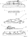
- Figure 4 shows the assembled detector according to the present embodiment in section view.
- a detection chamber 111 is formed above the bench assembly 9. Air is directed into this chamber from outside the detector through inlets 8 and vents 4. When smoke enters chamber 111, the beam of light is scattered towards the sensor, as described above. The mechanism of enabling air/smoke penetration into the chamber 111 is discussed in more detail below.
- the chamber 111 is of broadly cylindrical construction.
- the chamber layer 3 when assembled, the chamber layer 3 is fitted on to the circuit board 24.
- the chamber 3 comprises a hole into which the bench assembly slots.
- a section view of the chamber assembly according to this embodiment is shown in figure 5 .
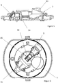
- a plan view of the assembly is shown in figure 6 .
- the chamber layer comprises a light trap 11.
- the light trap 11 When assembled, the light trap 11 is mounted radially of the detector 1 and diametrically opposite the light source contained within the bench assembly 9, as can be seen in figures 5 and 6 .
- the light detector 30, located in the arm 46 of the bench assembly 9 (see figure 3 and accompanying description) is positioned between the light source and the light trap.
- the purpose of the light trap is to trap any light which is unscattered by smoke particles and to prevent it from being reflected around the chamber, particularly onto the light sensor.
- the light trap 11 acts to effectively absorb the beam of light from the bench assembly 9 preventing further reflections around the chamber.
- the light trap is sized such that it encompasses the majority of the beam from the light source. In this example, the diameter of the cone opening is about twice the optical beam width, and is sized such that any undesired reflections from accumulated dust particles on the prism 38 or the lens 150 that exit the bench aperture 164 are collected by the cone.
- FIG. 6 A schematic section diagram of the light trap and bench assembly according to this embodiment is shown in Figure 6 .
- FIG 7 A schematic plan diagram of the chamber 111 is shown in Figure 7 .
- the position of the light trap (in this embodiment, a cone) 11 is configured such that the solid angle of the beam 13 is captured after passing over the photodiode 30.
- the chamber housing is generally cylindrical and the light trap is disposed radially of the detector and diametrically opposite the emitter.
- the light trap 11 is a right-circular cone. This has an axis of rotational symmetry parallel to the optical axis or on it. However, other shapes not falling within the scope of the claims may be used.
- the key features of the light trap are that the light trap comprises a three-dimensional surface which is open at the end which receives the beam of light but is otherwise closed.
- the inner wall surface should be continuous, without transverse edges or sharp portions.
- one or more of the walls of the light trap slope from the mouth of the light trap (the open end) to the narrower, opposite end of the trap. Thus the light trap becomes narrower downstream relative to the beam.
- the light beam enters the light trap through the wide open end, or the mouth of the light trap, and is subsequently reflected on the internal walls of the light trap. Because the light trap has one or more walls which slope towards the narrower, downstream end of the trap, reflection on a sloping wall or walls directs the light beam forwards and further into the light trap, necessitating further reflections before the beam is able to escape from the trap. No part of the inner wall surface is angled such as to reflect the light rays from an axial direction backwards. As reflections attenuate the beam, this process reduces the amount of light which escapes into the detection chamber. Because the light trap is open only at one end, the accumulation of dust on the surfaces of the light trap are minimised.
- the light trap 11 is as large as possible within the confines of the disc-shaped chamber layer 5.
- the axial length of its internal surface is approximately one half the outer radius of the smoke detector 1. This proportion is preferably in the range 0.3 to 0.7, preferably 0.4 to 0.6.
- Examples of possible shapes which do not fall within the scope of the claims other than a right circular cone and which are suitable for forming the light trap include shapes which have side walls which slope towards each other or top and bottom walls which slope towards each other such as a prism or polyhedron.
- the walls of the trap may be flat such as a pyramid or they may be curved such as an oblique cone.
- the narrow end of the trap may be the apex of a generally conical shape or it may be flat such as a frustrated cone or curved such as a hemisphere. Any other shape comprising the features described in the preceding paragraph may also be employed as light trap.
- the bench assembly 9 and light trap are configured such that the beam of light forms an image of the LED at point 125, in the centre of the cavity and above the light sensor located in the arm of the bench assembly.
- the beam of light then diverges into the light trap via an unobstructed optical path.
- the open end of the light trap 11 is sized such that it encompasses substantially the whole of the solid angle of the beam of light.
- substantially the whole of the solid angle of the beam of light substantially the whole of the solid angle created by the divergence of the beam from point 125 above the senor 30 is meant, as is shown in Figure 7 .
- FIG. 9 A more simplified schematic of a plan view of a chamber is shown in Figure 9 which shows the direction of the beam of light and a cone 11.
- the surfaces of the cone 11 make an angle ⁇ with the axis of the cone.
- the internal angle between the axis of the cone and the surface ⁇ is chosen to maximise the number of reflections that each ray makes.
- ⁇ is less than 45°, ensuring at least two reflections before emerging from the cone.
- the axis of the cone is parallel to, but offset laterally from, the optical axis of the beam of light.
- Figure 10 shows the path of a single ray of light entering the cone from the light source.
- ⁇ 22.5° and the ray experiences 4 reflections within the cone before it leaves the cone.
- dark plastic is chosen for the internal cone surface.
- each reflection attenuates more than 90% of the incident light.
- the compound attenuation of all reflections within the cone is thus greater than 0.9999.
- the cone light trap according to the above embodiments has a broad open area for receiving the beam generated within the chamber and tapers to a single apex.
- the cone is mounted slightly away from the optical axis of the beam.
- the cone is mounted slightly above, typically by one beam diameter, the optical axis of the beam.
- the axis of the cone is preferably parallel to the beam axis, but small deviations are allowable. This eliminates the need for a sharp point at the apex of the cone, enabling straightforward manufacture in thermoplastics.
- the simple design of the cone is easy to manufacture.
- the cone requires no sharp edges to achieve its performance, thereby limiting the effects of tooling wear.
- the large mouth of the cone permits easy cleaning for limiting the effects of the accumulation of dust on the cone surfaces.
- the light trap is moulded.
- the light trap is moulded from thermoplastics, advantageously polycarbonate or ABS.
- the light trap is formed by injection moulding. The technique of injection moulding is well known in the art.
- the light trap is moulded from dark, polished plastic.
- the internal surface finish of the light trap is chosen so that reflections are predominantly specular (as opposed to diffuse), producing the reflection pattern shown in Figure 10 .
- the light trap is moulded in two parts. The mould tool surface is polished to a mirror surface finish.
- the light trap effectively reduces stray reflections between light source and photo detector due to its size and shape. Since its function and location is separate from the air/smoke entry, the light is subject to limited accumulated dust on its working surfaces, being open at one end only. In addition, since stray light is so effectively absorbed at the light trap, accumulation of dust on other internal chamber surfaces does not have a substantial effect on the amount of stray reflections. In product performance terms, this translates to the ability to have long usage in dusty environments before the operation of the sensor is compromised.
- a light trap according to embodiments described above is compact and efficient at attenuating the unscattered light beam.
- the efficiency of the tapering shape at attenuating the light is such that no peripheral baffles are required in the chamber for further absorption of light.
- the space-efficiency of the light trap and the fact the unscattered light is captured relatively closely to the photodiode means that other components such as thermistors may be incorporated easily into the design of the smoke detector. Because the light is dealt with at the light trap, there is no risk of unwanted reflections and therefore a reduction in performance caused by the incorporation of such additional components.
- a portion of the light trap is detachable. This is shown in figure 11 , in which an exploded section view of the chamber layer according to the embodiment is shown.
- the upper portion 113 of the cone 11 is detachable for easy manufacture and cleaning.
- the upper portion 113 comprises legs 115 which hook into holes formed in the chamber layer 5 thereby securing it to the chamber layer 5.
- the lower portion of the cone 11 is formed integrally with the remainder of the chamber layer 5. Forming the cone in this way, with two halves that clip together on assembly during manufacture, simplifies production.
- the embodiments described above employ a bench and surface mount LED and photo detector
- the light dump according to the embodiments described above may equally be employed with other LED-photo detector configurations.
- the light dump is employed with a through-hole LED and/or photodetector.
- Such an LED has electrical leads and is horizontally mounted to emit the beam horizontally along the same optical axis.
- a second requirement of the chamber is to ensure that external light does not reach the photo detector, while permitting air and smoke to reach the light sensor.
- FIG. 12 shows a section view of a detector according to the embodiment.
- the solid arrows indicate the direction air must take in order to travel from outside of the chamber into the cavity 111.
- the air enters through vents 8 and is then forced into a U-shaped path 117.
- the air enters the chamber through the chamber cover 6, in particular through the vents 4 formed in chamber cover 6.
- the serpentine profile of the air inlet is achieved by introducing two vertical walls. These are shown in the figure 13 , which shows a section view of a detector according to the embodiment.
- the first wall 119 abruptly disturbs the airflow, forcing the air to change direction and slow.
- the second wall 121 slows down the airflow further and is redirected towards the centre of the chamber.
- Figure 14 shows a section view of a detector according to the example, with optical components omitted for clarity.
- This arrangement of walls prevents dust from entering the chamber, thereby preventing the detector going into alarm due to accumulation of dust.
- dust loaded air hits either of the walls the dust particles are deposited as they are generally larger than smoke particles.
- the smoke aerosol is relatively unimpeded by the serpentine. Therefore this serpentine ensures that a low quantity of dust enters the chamber, ensuring a low number of false alarms due to dust accumulation.
- the dimensions of the serpentine are chosen to optimise the impeding of dust whilst allowing the complete spectrum of smoke to enter the chamber.
- the wall 119 has a height which is a compromise between impeding dust ingress and admitting smoke. The same applies to the depth of the channel opposite the wall 119, i.e. the height of the wall 121.
- the geometry chosen in this embodiment provides a serpentine flow channel of approximately constant width, i.e. the air flow path is of near constant cross-section as it bends.
- the principal function of the mesh is to prevent the ingress of objects larger than 0.4mm diameter, such as insects. It also prevents large dust clumps and/or fibres entering the chamber. It is important to place this after the serpentine, as the serpentine itself may contribute to the formation of large clumps of dust which could subsequently be dislodged and enter the chamber.
- vents 4 of chamber cover 6 are covered with a vertical mesh.
- the two-wall arrangement according to this embodiment further prevents the entry of light into the chamber. Typically, when light hits a surface and is reflected, the intensity of the light is reduced by a factor of 10.
- the U shaped inlet formed by the two-wall arrangement means that any light entering the chamber would typically need to reflect more than four times before reaching the chamber.
- Figure 16 shows the path taken by a ray of light 123 in order to reach the light sensor 30 from outside of the detector. Four reflections are taken by the light before reaching the detector.
- Detectors according to examples described above employ both the serpentine air-path and light dump described above in combination. However, they may be employed separately.
- the light dump is employed with a design of air inlet which is different from the serpentine air-inlet.
- the serpentine air-inlet is employed with a different light-attenuating component.
Landscapes
- Physics & Mathematics (AREA)
- General Physics & Mathematics (AREA)
- Chemical & Material Sciences (AREA)
- Analytical Chemistry (AREA)
- Business, Economics & Management (AREA)
- Emergency Management (AREA)
- Optics & Photonics (AREA)
- Health & Medical Sciences (AREA)
- Life Sciences & Earth Sciences (AREA)
- Biochemistry (AREA)
- General Health & Medical Sciences (AREA)
- Immunology (AREA)
- Pathology (AREA)
- Fire-Detection Mechanisms (AREA)
- Investigating Or Analysing Materials By Optical Means (AREA)
Claims (6)
- Rauchdetektor, umfassend:eine Abdeckung (7), welche auf eine Basis (1) passt;eine Leiterplatte (24);eine Kammerschicht (5) und eine Kammerabdeckung (6), wobei die Kammerabdeckung (6) auf die Kammerschicht (5) passt, wobei die Kammerschicht (5) auf die Basis (1) zwischen der Abdeckung (7) und der Basis (1) passt;eine Lichtquelle (26) zum Erzeugen eines Lichtstrahls und angeordnet, um den Strahl entlang einer optischen Achse zu übertragen;einen Sensor (30) zum Empfangen von Licht, welches von dem Strahl aus der optischen Achse durch Rauch gestreut wird; undeine Lichtfalle (11), welche eine oder mehrere Wände umfasst, welche ein Volumen zum Empfangen von Licht definieren, welches ungestreut von der Lichtquelle (26) an dem Sensor (30) vorbei entlang der optischen Achse durchtritt,wobei das Volumen umfasst:ein erstes Ende, welches auf der optischen Achse der Lichtquelle (26) am nächsten liegt;und ein zweites Ende, welches auf der optischen Achse von der Lichtquelle (26) am weitesten liegt;wobei das Volumen an dem ersten Ende offen aber anderseits geschlossen ist, undwobei mindestens eine der Wände von dem ersten Ende zu dem zweiten Ende geneigt ist, sodass die Lichtfalle (11) sich allmählich von dem ersten Ende axial zum zweiten Ende hin verengt, und wobei das offene erste Ende im Wesentlichen den ganzen Raumwinkel des Strahls einschließt,wobei die Lichtfalle (11), wenn von der Seite des Rauchdetektors gesehen, Wände umfasst, welche sich oberhalb und unterhalb einer Richtung erstrecken, welche parallel zur oder übereinstimmend mit der optischen Achse ist und Wände, welche sich entlang der Richtung erstrecken, undwobei die Wände der Lichtfalle (11), welche sich oberhalb und unterhalb der Richtung erstrecken, zueinander in der Richtung von dem ersten Ende zu dem zweiten Ende geneigt sind,wobei die Lichtfalle (11) ein Konus ist,wobei der Konus ein gerader kreisförmiger Konus ist,wobei der Konus einen oberen Abschnitt (113) und einen unteren Abschnitt umfasst,wobei der obere Abschnitt (113) Beine (115) umfasst, welche sich in Löchern in der Kammerschicht (5) einhaken, wodurch dieser in der Kammerschicht (5) befestigt wird,wobei der untere Abschnitt einstückig mit dem Rest der Kammerschicht (5) geformt ist, wobei der obere Abschnitt von dem unteren Abschnitt abnehmbar ist.
- Rauchdetektor nach einem der vorhergehenden Ansprüche, wobei die Lichtquelle (26), der Sensor und die Lichtfalle (11) innerhalb einer Kammer montiert sind und die Lichtfalle (11) nach innen von den Wänden der Kammer zu der Lichtquelle (26) hin vorsteht.
- Rauchdetektor nach Anspruch 2,
wobei die Basis (1) eine im Wesentlichen kreisförmige Scheibenform aufweist und die Kammerabdeckung (6) eine im Wesentlichen kreisförmige Kuppelform aufweist, welche zwischen diesen die Kammerschicht (5) umfassend die Lichtquelle (26), den Sensor (30) und die Lichtfalle (11) enthalten, wobei die Lichtfalle (11) montiert ist, sodass ihre Achse auf einem Radius des Rauchdetektors liegt und die Kammerabdeckung einen umfangsmäßigen serpentinenförmigen Lufteingang (8) aufweist, um mit Rauch belastete Luft in die Kammer eindringen zu lassen aber direktes Licht von außen zu blockieren. - Rauchdetektor nach einem der vorhergehenden Ansprüche, wobei der Sensor (30) zwischen der Lichtquelle (26) und der Lichtfalle (11) angeordnet ist.
- Rauchdetektor nach einem der vorhergehenden Ansprüche, wobei ein ungehinderter optischer Pfad zwischen der Lichtquelle (26) und der Lichtfalle (11) besteht.
- Rauchdetektor nach einem der vorhergehenden Ansprüche, wobei der Sensor (30) mindestens einen Teil des Lichts direkt empfängt, welches von dem Strahl aus der optischen Achse durch Rauch gestreut wird.
Applications Claiming Priority (2)
| Application Number | Priority Date | Filing Date | Title |
|---|---|---|---|
| GB1410717.1A GB2531495B (en) | 2014-06-16 | 2014-06-16 | Smoke detector |
| PCT/GB2015/051766 WO2015193660A1 (en) | 2014-06-16 | 2015-06-16 | Conical light absorber for smoke detector |
Publications (2)
| Publication Number | Publication Date |
|---|---|
| EP3155602A1 EP3155602A1 (de) | 2017-04-19 |
| EP3155602B1 true EP3155602B1 (de) | 2021-11-17 |
Family
ID=51266677
Family Applications (1)
| Application Number | Title | Priority Date | Filing Date |
|---|---|---|---|
| EP15732882.4A Active EP3155602B1 (de) | 2014-06-16 | 2015-06-16 | Konischer lichtabsorber für rauchdetektoren |
Country Status (8)
| Country | Link |
|---|---|
| US (1) | US10019879B2 (de) |
| EP (1) | EP3155602B1 (de) |
| CN (1) | CN106574989B (de) |
| AU (2) | AU2015275879A1 (de) |
| GB (1) | GB2531495B (de) |
| RU (1) | RU2017100946A (de) |
| SA (1) | SA516380494B1 (de) |
| WO (1) | WO2015193660A1 (de) |
Families Citing this family (24)
| Publication number | Priority date | Publication date | Assignee | Title |
|---|---|---|---|---|
| WO2017073562A1 (ja) * | 2015-10-26 | 2017-05-04 | ホーチキ株式会社 | 警報装置 |
| CN106018367A (zh) * | 2016-06-29 | 2016-10-12 | 力合科技(湖南)股份有限公司 | 一种抗干扰装置及原子荧光分析仪 |
| EP3270362B1 (de) | 2017-02-07 | 2019-01-02 | Siemens Schweiz AG | Brandmelder mit einer messkammer und mit einem schaltungsträger zur gemeinsamen anordnung eines brandsensors der messkammer sowie zumindest eines weiteren sensors zur erfassung einer messgrösse in der umgebung ausserhalb des brandmelders |
| CN110709902B (zh) * | 2017-06-14 | 2021-09-14 | 报知希株式会社 | 警报装置 |
| EP3483585B1 (de) | 2017-11-13 | 2022-06-29 | Carrier Corporation | Luftpartikeldetektionssystem |
| ES2977482T3 (es) | 2018-05-09 | 2024-08-26 | Carrier Corp | Cámara de humo para detector de humo multi-ángulo multi-onda |
| WO2019228635A1 (en) | 2018-05-31 | 2019-12-05 | Autronica Fire & Security As | Printed circuit board for smoke detector |
| CN108573591A (zh) * | 2018-07-18 | 2018-09-25 | 中国科学技术大学 | 一种散射型火灾烟雾探测器及其光吸收器 |
| JP7338956B2 (ja) * | 2018-07-24 | 2023-09-05 | ホーチキ株式会社 | 火災検出装置 |
| JP7208731B2 (ja) * | 2018-07-24 | 2023-01-19 | ホーチキ株式会社 | 火災検出装置 |
| CN109754565B (zh) * | 2019-01-29 | 2020-12-22 | 山东省科学院自动化研究所 | 一种光电感烟烟雾探测暗室 |
| US11074796B2 (en) * | 2019-04-01 | 2021-07-27 | Carrier Corporation | Photoelectric smoke detectors |
| CN110412669A (zh) * | 2019-08-13 | 2019-11-05 | 哈尔滨工业大学 | 一种用于波长为1053nm光波的主动吸收体装置 |
| GB2586283B (en) | 2019-08-16 | 2022-01-26 | Apollo Fire Detectors Ltd | Optical smoke detector |
| GB2586784B (en) | 2019-08-30 | 2022-05-04 | Computionics Ltd | Improvements to smoke detectors |
| DE102020123148A1 (de) | 2020-09-04 | 2022-03-10 | Marelli Automotive Lighting Reutlingen (Germany) GmbH | Kraftfahrzeugbeleuchtungseinrichtung mit verdeckter optischer Vorrichtung |
| CN111951517A (zh) * | 2020-09-16 | 2020-11-17 | 深圳市泛海三江电子股份有限公司 | 一种新型光电烟感探测器 |
| US11790746B2 (en) * | 2021-02-02 | 2023-10-17 | Carrier Corporation | Smoke entry solution for multi wave multi angle safety device |
| US12198531B2 (en) * | 2022-01-19 | 2025-01-14 | Tyco Fire & Security Gmbh | Smoke detector self-test |
| US12046114B2 (en) * | 2022-02-07 | 2024-07-23 | Pixart Imaging Inc. | Smoke detection device with preferred detection accuracy |
| CN116577250A (zh) * | 2022-02-08 | 2023-08-11 | 开利公司 | 组合烟雾和空气质量检测 |
| GB2639464A (en) * | 2022-11-25 | 2025-09-24 | Mavili Elektronik Ticaret Ve Sanayii Anonim Sirketi | Particle detection device |
| US20250244222A1 (en) * | 2024-01-29 | 2025-07-31 | Pixart Imaging Inc. | Optical smoke detector with light trap, and light guiding and blocking member thereof |
| ES3035017A1 (es) * | 2024-02-23 | 2025-08-27 | Detnov Security S L | Dispositivo separador de particulas para detectores de incendio |
Citations (2)
| Publication number | Priority date | Publication date | Assignee | Title |
|---|---|---|---|---|
| GB2251067A (en) * | 1990-12-17 | 1992-06-24 | E I Company Limited | Smoke detector |
| US20050242967A1 (en) * | 2004-04-21 | 2005-11-03 | Nittan Company, Limited | Smoke detector |
Family Cites Families (25)
| Publication number | Priority date | Publication date | Assignee | Title |
|---|---|---|---|---|
| US3361030A (en) * | 1961-09-21 | 1968-01-02 | Leonard J. Goldberg | System and method for detecting small particles |
| CH417405A (de) * | 1964-07-14 | 1966-07-15 | Cerberus Ag Werk Fuer Elektron | Vorrichtung zur Feststellung von Aerosolen in Luft |
| GB1419146A (en) * | 1972-06-06 | 1975-12-24 | Commw Scient Ind Res Org | Smoke detector |
| US4121110A (en) * | 1976-11-04 | 1978-10-17 | Solomon Elias E | Optically biased smoke detector |
| EP0135361B1 (de) * | 1983-08-12 | 1995-04-26 | I.E.I. Pty Ltd A.C.N. 053 531 212 | Gerät zur Detektion von Partikeln in Suspension |
| US4618777A (en) * | 1984-11-19 | 1986-10-21 | Pittway Corporation | Outer electrode with improved smoke entry |
| US4906978A (en) * | 1986-12-24 | 1990-03-06 | Cerberus Ag | Optical smoke detector |
| US4857895A (en) * | 1987-08-31 | 1989-08-15 | Kaprelian Edward K | Combined scatter and light obscuration smoke detector |
| WO1997019338A1 (en) * | 1995-11-20 | 1997-05-29 | Venturedyne, Ltd. | Particle sensor with fiber optic conductor |
| AUPN965896A0 (en) * | 1996-05-03 | 1996-05-30 | Vision Products Pty Ltd | The detection of airborne pollutants |
| EP1475866B1 (de) * | 1996-07-01 | 2007-03-28 | Matsushita Electric Industrial Co., Ltd. | Lasergerät |
| US5872361A (en) * | 1997-03-24 | 1999-02-16 | Hach Company | Turbidimeter with non-imaging optical concentrator |
| GB9721861D0 (en) * | 1997-10-15 | 1997-12-17 | Kidde Fire Protection Ltd | High sensitivity particle detection |
| JP2000065741A (ja) * | 1998-08-25 | 2000-03-03 | Matsushita Electric Works Ltd | 光電式感知器 |
| US6057774A (en) * | 1999-01-21 | 2000-05-02 | Brk Brands, Inc. | Smoke alarm with anti-dust screen |
| GB2379977B (en) * | 2001-09-25 | 2005-04-06 | Kidde Plc | High sensitivity particle detection |
| JP3934423B2 (ja) * | 2002-01-11 | 2007-06-20 | ホーチキ株式会社 | 散乱光式煙感知器 |
| US6758568B2 (en) * | 2002-05-10 | 2004-07-06 | The Boeing Company | Light trap and associated light focusing assembly |
| GB2404731B (en) | 2003-07-31 | 2006-08-09 | Apollo Fire Detectors Ltd | Smoke detector with compact light source |
| CN101135629A (zh) * | 2003-10-23 | 2008-03-05 | 马丁·T·科尔 | 适于安装到管道上的壳体装置及在管道上安装壳体的方法 |
| JP4405522B2 (ja) * | 2007-03-07 | 2010-01-27 | シャープ株式会社 | 光電式煙センサおよび照明機器 |
| US20120262714A1 (en) * | 2011-04-12 | 2012-10-18 | Gonzales Eric V | Low profile, high flowthrough smoke chamber |
| JP5993253B2 (ja) * | 2012-09-06 | 2016-09-14 | 能美防災株式会社 | 煙感知器 |
| DE112013004749T5 (de) * | 2012-09-27 | 2015-06-18 | Mitsubishi Electric Corporation | Leistungsdämpfer, Laserleistungs-Messeinrichtung, Laserleistungs-Messverfahren und Laserleistungs-Überwachungssystem |
| DE102012219635A1 (de) * | 2012-10-26 | 2014-02-13 | Trumpf Laser Gmbh + Co. Kg | Vorrichtung zur Absorption eines Laserstrahls |
-
2014
- 2014-06-16 GB GB1410717.1A patent/GB2531495B/en active Active
-
2015
- 2015-06-16 CN CN201580031919.XA patent/CN106574989B/zh active Active
- 2015-06-16 AU AU2015275879A patent/AU2015275879A1/en not_active Abandoned
- 2015-06-16 WO PCT/GB2015/051766 patent/WO2015193660A1/en not_active Ceased
- 2015-06-16 RU RU2017100946A patent/RU2017100946A/ru not_active Application Discontinuation
- 2015-06-16 EP EP15732882.4A patent/EP3155602B1/de active Active
- 2015-06-16 US US15/316,207 patent/US10019879B2/en active Active
-
2016
- 2016-12-13 SA SA516380494A patent/SA516380494B1/ar unknown
-
2018
- 2018-09-26 AU AU2018236753A patent/AU2018236753B2/en active Active
Patent Citations (2)
| Publication number | Priority date | Publication date | Assignee | Title |
|---|---|---|---|---|
| GB2251067A (en) * | 1990-12-17 | 1992-06-24 | E I Company Limited | Smoke detector |
| US20050242967A1 (en) * | 2004-04-21 | 2005-11-03 | Nittan Company, Limited | Smoke detector |
Also Published As
| Publication number | Publication date |
|---|---|
| AU2015275879A1 (en) | 2017-02-02 |
| GB2531495A (en) | 2016-04-27 |
| GB2531495B (en) | 2017-04-12 |
| WO2015193660A1 (en) | 2015-12-23 |
| CN106574989B (zh) | 2019-12-03 |
| EP3155602A1 (de) | 2017-04-19 |
| GB201410717D0 (en) | 2014-07-30 |
| AU2018236753A1 (en) | 2018-10-18 |
| US20170162019A1 (en) | 2017-06-08 |
| RU2017100946A (ru) | 2018-07-16 |
| SA516380494B1 (ar) | 2020-08-26 |
| CN106574989A (zh) | 2017-04-19 |
| AU2018236753B2 (en) | 2020-10-15 |
| RU2017100946A3 (de) | 2018-11-06 |
| US10019879B2 (en) | 2018-07-10 |
Similar Documents
| Publication | Publication Date | Title |
|---|---|---|
| AU2018236753B2 (en) | Conical light absorber for smoke detector | |
| US6756905B2 (en) | Photoelectric smoke detector and chamber therefor | |
| US4906978A (en) | Optical smoke detector | |
| KR101905275B1 (ko) | 입자 센서 및 그것을 구비한 전자 기기 | |
| DK2685437T3 (en) | Fire sensor | |
| JPH08233736A (ja) | 微粒子検出センサ | |
| EP3884477B1 (de) | Rauchdetektor | |
| CN209248721U (zh) | 迷宫式光学探测器 | |
| CN210863533U (zh) | 一种黑烟白烟同一灵敏度的点型光电感烟探测器 | |
| EP2166520A1 (de) | Rauchmelder | |
| JP2010238095A (ja) | 光電式煙感知器 | |
| JP5534696B2 (ja) | 光電式煙感知器 | |
| JP5133157B2 (ja) | 光電式煙感知器 | |
| JP5046552B2 (ja) | 光電式煙感知器 | |
| JP2016130882A (ja) | 光電式煙感知器 | |
| JP5325397B2 (ja) | 煙感知器 | |
| CN109754565B (zh) | 一种光电感烟烟雾探测暗室 | |
| JP5153709B2 (ja) | 光電式煙感知器 | |
| CN111951518B (zh) | 用于光电感烟的探测装置 | |
| PL184227B1 (pl) | Czujka dymu | |
| JP5606123B2 (ja) | 光電式煙感知器 | |
| JP5038112B2 (ja) | 光電式煙感知器 | |
| JP5117820B2 (ja) | 光電式煙感知器 | |
| CN223770001U (zh) | 颗粒物浓度检测装置 | |
| CN121686656A (zh) | 一种水平双光路迷宫组件及感烟探测器 |
Legal Events
| Date | Code | Title | Description |
|---|---|---|---|
| STAA | Information on the status of an ep patent application or granted ep patent |
Free format text: STATUS: THE INTERNATIONAL PUBLICATION HAS BEEN MADE |
|
| PUAI | Public reference made under article 153(3) epc to a published international application that has entered the european phase |
Free format text: ORIGINAL CODE: 0009012 |
|
| STAA | Information on the status of an ep patent application or granted ep patent |
Free format text: STATUS: REQUEST FOR EXAMINATION WAS MADE |
|
| 17P | Request for examination filed |
Effective date: 20161209 |
|
| AK | Designated contracting states |
Kind code of ref document: A1 Designated state(s): AL AT BE BG CH CY CZ DE DK EE ES FI FR GB GR HR HU IE IS IT LI LT LU LV MC MK MT NL NO PL PT RO RS SE SI SK SM TR |
|
| AX | Request for extension of the european patent |
Extension state: BA ME |
|
| DAV | Request for validation of the european patent (deleted) | ||
| DAX | Request for extension of the european patent (deleted) | ||
| STAA | Information on the status of an ep patent application or granted ep patent |
Free format text: STATUS: EXAMINATION IS IN PROGRESS |
|
| 17Q | First examination report despatched |
Effective date: 20180417 |
|
| GRAJ | Information related to disapproval of communication of intention to grant by the applicant or resumption of examination proceedings by the epo deleted |
Free format text: ORIGINAL CODE: EPIDOSDIGR1 |
|
| STAA | Information on the status of an ep patent application or granted ep patent |
Free format text: STATUS: GRANT OF PATENT IS INTENDED |
|
| GRAP | Despatch of communication of intention to grant a patent |
Free format text: ORIGINAL CODE: EPIDOSNIGR1 |
|
| RIN1 | Information on inventor provided before grant (corrected) |
Inventor name: WATSON, PHILIP Inventor name: KNIGHT, ROBERT, DAVID Inventor name: CRUSE, GREGORY MICHAEL |
|
| INTG | Intention to grant announced |
Effective date: 20210222 |
|
| GRAJ | Information related to disapproval of communication of intention to grant by the applicant or resumption of examination proceedings by the epo deleted |
Free format text: ORIGINAL CODE: EPIDOSDIGR1 |
|
| STAA | Information on the status of an ep patent application or granted ep patent |
Free format text: STATUS: EXAMINATION IS IN PROGRESS |
|
| INTC | Intention to grant announced (deleted) | ||
| RBV | Designated contracting states (corrected) |
Designated state(s): AL AT BE BG CH CY CZ DE DK EE ES FI FR GR HR HU IE IS IT LI LT LU LV MC MK MT NL NO PL PT RO RS SE SI SK SM TR |
|
| GRAS | Grant fee paid |
Free format text: ORIGINAL CODE: EPIDOSNIGR3 |
|
| STAA | Information on the status of an ep patent application or granted ep patent |
Free format text: STATUS: GRANT OF PATENT IS INTENDED |
|
| GRAP | Despatch of communication of intention to grant a patent |
Free format text: ORIGINAL CODE: EPIDOSNIGR1 |
|
| INTG | Intention to grant announced |
Effective date: 20210915 |
|
| GRAA | (expected) grant |
Free format text: ORIGINAL CODE: 0009210 |
|
| STAA | Information on the status of an ep patent application or granted ep patent |
Free format text: STATUS: THE PATENT HAS BEEN GRANTED |
|
| AK | Designated contracting states |
Kind code of ref document: B1 Designated state(s): AL AT BE BG CH CY CZ DE DK EE ES FI FR GR HR HU IE IS IT LI LT LU LV MC MK MT NL NO PL PT RO RS SE SI SK SM TR |
|
| REG | Reference to a national code |
Ref country code: DE Ref legal event code: R096 Ref document number: 602015075068 Country of ref document: DE |
|
| REG | Reference to a national code |
Ref country code: IE Ref legal event code: FG4D |
|
| REG | Reference to a national code |
Ref country code: AT Ref legal event code: REF Ref document number: 1448719 Country of ref document: AT Kind code of ref document: T Effective date: 20211215 |
|
| REG | Reference to a national code |
Ref country code: NL Ref legal event code: FP |
|
| REG | Reference to a national code |
Ref country code: LT Ref legal event code: MG9D |
|
| REG | Reference to a national code |
Ref country code: AT Ref legal event code: MK05 Ref document number: 1448719 Country of ref document: AT Kind code of ref document: T Effective date: 20211117 |
|
| PG25 | Lapsed in a contracting state [announced via postgrant information from national office to epo] |
Ref country code: RS Free format text: LAPSE BECAUSE OF FAILURE TO SUBMIT A TRANSLATION OF THE DESCRIPTION OR TO PAY THE FEE WITHIN THE PRESCRIBED TIME-LIMIT Effective date: 20211117 Ref country code: LT Free format text: LAPSE BECAUSE OF FAILURE TO SUBMIT A TRANSLATION OF THE DESCRIPTION OR TO PAY THE FEE WITHIN THE PRESCRIBED TIME-LIMIT Effective date: 20211117 Ref country code: FI Free format text: LAPSE BECAUSE OF FAILURE TO SUBMIT A TRANSLATION OF THE DESCRIPTION OR TO PAY THE FEE WITHIN THE PRESCRIBED TIME-LIMIT Effective date: 20211117 Ref country code: BG Free format text: LAPSE BECAUSE OF FAILURE TO SUBMIT A TRANSLATION OF THE DESCRIPTION OR TO PAY THE FEE WITHIN THE PRESCRIBED TIME-LIMIT Effective date: 20220217 Ref country code: AT Free format text: LAPSE BECAUSE OF FAILURE TO SUBMIT A TRANSLATION OF THE DESCRIPTION OR TO PAY THE FEE WITHIN THE PRESCRIBED TIME-LIMIT Effective date: 20211117 |
|
| PG25 | Lapsed in a contracting state [announced via postgrant information from national office to epo] |
Ref country code: IS Free format text: LAPSE BECAUSE OF FAILURE TO SUBMIT A TRANSLATION OF THE DESCRIPTION OR TO PAY THE FEE WITHIN THE PRESCRIBED TIME-LIMIT Effective date: 20220317 Ref country code: SE Free format text: LAPSE BECAUSE OF FAILURE TO SUBMIT A TRANSLATION OF THE DESCRIPTION OR TO PAY THE FEE WITHIN THE PRESCRIBED TIME-LIMIT Effective date: 20211117 Ref country code: PT Free format text: LAPSE BECAUSE OF FAILURE TO SUBMIT A TRANSLATION OF THE DESCRIPTION OR TO PAY THE FEE WITHIN THE PRESCRIBED TIME-LIMIT Effective date: 20220317 Ref country code: PL Free format text: LAPSE BECAUSE OF FAILURE TO SUBMIT A TRANSLATION OF THE DESCRIPTION OR TO PAY THE FEE WITHIN THE PRESCRIBED TIME-LIMIT Effective date: 20211117 Ref country code: NO Free format text: LAPSE BECAUSE OF FAILURE TO SUBMIT A TRANSLATION OF THE DESCRIPTION OR TO PAY THE FEE WITHIN THE PRESCRIBED TIME-LIMIT Effective date: 20220217 Ref country code: LV Free format text: LAPSE BECAUSE OF FAILURE TO SUBMIT A TRANSLATION OF THE DESCRIPTION OR TO PAY THE FEE WITHIN THE PRESCRIBED TIME-LIMIT Effective date: 20211117 Ref country code: HR Free format text: LAPSE BECAUSE OF FAILURE TO SUBMIT A TRANSLATION OF THE DESCRIPTION OR TO PAY THE FEE WITHIN THE PRESCRIBED TIME-LIMIT Effective date: 20211117 Ref country code: GR Free format text: LAPSE BECAUSE OF FAILURE TO SUBMIT A TRANSLATION OF THE DESCRIPTION OR TO PAY THE FEE WITHIN THE PRESCRIBED TIME-LIMIT Effective date: 20220218 Ref country code: ES Free format text: LAPSE BECAUSE OF FAILURE TO SUBMIT A TRANSLATION OF THE DESCRIPTION OR TO PAY THE FEE WITHIN THE PRESCRIBED TIME-LIMIT Effective date: 20211117 |
|
| PG25 | Lapsed in a contracting state [announced via postgrant information from national office to epo] |
Ref country code: SM Free format text: LAPSE BECAUSE OF FAILURE TO SUBMIT A TRANSLATION OF THE DESCRIPTION OR TO PAY THE FEE WITHIN THE PRESCRIBED TIME-LIMIT Effective date: 20211117 Ref country code: SK Free format text: LAPSE BECAUSE OF FAILURE TO SUBMIT A TRANSLATION OF THE DESCRIPTION OR TO PAY THE FEE WITHIN THE PRESCRIBED TIME-LIMIT Effective date: 20211117 Ref country code: RO Free format text: LAPSE BECAUSE OF FAILURE TO SUBMIT A TRANSLATION OF THE DESCRIPTION OR TO PAY THE FEE WITHIN THE PRESCRIBED TIME-LIMIT Effective date: 20211117 Ref country code: EE Free format text: LAPSE BECAUSE OF FAILURE TO SUBMIT A TRANSLATION OF THE DESCRIPTION OR TO PAY THE FEE WITHIN THE PRESCRIBED TIME-LIMIT Effective date: 20211117 Ref country code: DK Free format text: LAPSE BECAUSE OF FAILURE TO SUBMIT A TRANSLATION OF THE DESCRIPTION OR TO PAY THE FEE WITHIN THE PRESCRIBED TIME-LIMIT Effective date: 20211117 Ref country code: CZ Free format text: LAPSE BECAUSE OF FAILURE TO SUBMIT A TRANSLATION OF THE DESCRIPTION OR TO PAY THE FEE WITHIN THE PRESCRIBED TIME-LIMIT Effective date: 20211117 |
|
| REG | Reference to a national code |
Ref country code: DE Ref legal event code: R097 Ref document number: 602015075068 Country of ref document: DE |
|
| PLBE | No opposition filed within time limit |
Free format text: ORIGINAL CODE: 0009261 |
|
| STAA | Information on the status of an ep patent application or granted ep patent |
Free format text: STATUS: NO OPPOSITION FILED WITHIN TIME LIMIT |
|
| 26N | No opposition filed |
Effective date: 20220818 |
|
| PG25 | Lapsed in a contracting state [announced via postgrant information from national office to epo] |
Ref country code: AL Free format text: LAPSE BECAUSE OF FAILURE TO SUBMIT A TRANSLATION OF THE DESCRIPTION OR TO PAY THE FEE WITHIN THE PRESCRIBED TIME-LIMIT Effective date: 20211117 |
|
| PG25 | Lapsed in a contracting state [announced via postgrant information from national office to epo] |
Ref country code: SI Free format text: LAPSE BECAUSE OF FAILURE TO SUBMIT A TRANSLATION OF THE DESCRIPTION OR TO PAY THE FEE WITHIN THE PRESCRIBED TIME-LIMIT Effective date: 20211117 |
|
| PG25 | Lapsed in a contracting state [announced via postgrant information from national office to epo] |
Ref country code: MC Free format text: LAPSE BECAUSE OF FAILURE TO SUBMIT A TRANSLATION OF THE DESCRIPTION OR TO PAY THE FEE WITHIN THE PRESCRIBED TIME-LIMIT Effective date: 20211117 |
|
| REG | Reference to a national code |
Ref country code: CH Ref legal event code: PL |
|
| PG25 | Lapsed in a contracting state [announced via postgrant information from national office to epo] |
Ref country code: LU Free format text: LAPSE BECAUSE OF NON-PAYMENT OF DUE FEES Effective date: 20220616 Ref country code: LI Free format text: LAPSE BECAUSE OF NON-PAYMENT OF DUE FEES Effective date: 20220630 Ref country code: FR Free format text: LAPSE BECAUSE OF NON-PAYMENT OF DUE FEES Effective date: 20220630 Ref country code: CH Free format text: LAPSE BECAUSE OF NON-PAYMENT OF DUE FEES Effective date: 20220630 |
|
| PG25 | Lapsed in a contracting state [announced via postgrant information from national office to epo] |
Ref country code: IT Free format text: LAPSE BECAUSE OF FAILURE TO SUBMIT A TRANSLATION OF THE DESCRIPTION OR TO PAY THE FEE WITHIN THE PRESCRIBED TIME-LIMIT Effective date: 20211117 |
|
| PG25 | Lapsed in a contracting state [announced via postgrant information from national office to epo] |
Ref country code: HU Free format text: LAPSE BECAUSE OF FAILURE TO SUBMIT A TRANSLATION OF THE DESCRIPTION OR TO PAY THE FEE WITHIN THE PRESCRIBED TIME-LIMIT; INVALID AB INITIO Effective date: 20150616 |
|
| PG25 | Lapsed in a contracting state [announced via postgrant information from national office to epo] |
Ref country code: MK Free format text: LAPSE BECAUSE OF FAILURE TO SUBMIT A TRANSLATION OF THE DESCRIPTION OR TO PAY THE FEE WITHIN THE PRESCRIBED TIME-LIMIT Effective date: 20211117 Ref country code: CY Free format text: LAPSE BECAUSE OF FAILURE TO SUBMIT A TRANSLATION OF THE DESCRIPTION OR TO PAY THE FEE WITHIN THE PRESCRIBED TIME-LIMIT Effective date: 20211117 |
|
| PG25 | Lapsed in a contracting state [announced via postgrant information from national office to epo] |
Ref country code: MT Free format text: LAPSE BECAUSE OF FAILURE TO SUBMIT A TRANSLATION OF THE DESCRIPTION OR TO PAY THE FEE WITHIN THE PRESCRIBED TIME-LIMIT Effective date: 20211117 |
|
| PGFP | Annual fee paid to national office [announced via postgrant information from national office to epo] |
Ref country code: NL Payment date: 20250409 Year of fee payment: 11 |
|
| PGFP | Annual fee paid to national office [announced via postgrant information from national office to epo] |
Ref country code: DE Payment date: 20250402 Year of fee payment: 11 |
|
| PGFP | Annual fee paid to national office [announced via postgrant information from national office to epo] |
Ref country code: BE Payment date: 20250410 Year of fee payment: 11 |
|
| PGFP | Annual fee paid to national office [announced via postgrant information from national office to epo] |
Ref country code: IE Payment date: 20250402 Year of fee payment: 11 |
|
| PG25 | Lapsed in a contracting state [announced via postgrant information from national office to epo] |
Ref country code: TR Free format text: LAPSE BECAUSE OF FAILURE TO SUBMIT A TRANSLATION OF THE DESCRIPTION OR TO PAY THE FEE WITHIN THE PRESCRIBED TIME-LIMIT Effective date: 20211117 |