EP3155689B1 - Flachantenne zur satellitenkommunikation - Google Patents
Flachantenne zur satellitenkommunikation Download PDFInfo
- Publication number
- EP3155689B1 EP3155689B1 EP15728822.6A EP15728822A EP3155689B1 EP 3155689 B1 EP3155689 B1 EP 3155689B1 EP 15728822 A EP15728822 A EP 15728822A EP 3155689 B1 EP3155689 B1 EP 3155689B1
- Authority
- EP
- European Patent Office
- Prior art keywords
- radiating
- flat antenna
- antenna according
- network
- sensor
- Prior art date
- Legal status (The legal status is an assumption and is not a legal conclusion. Google has not performed a legal analysis and makes no representation as to the accuracy of the status listed.)
- Active
Links
Images

Classifications
-
- H—ELECTRICITY
- H01—ELECTRIC ELEMENTS
- H01Q—ANTENNAS, i.e. RADIO AERIALS
- H01Q9/00—Electrically-short antennas having dimensions not more than twice the operating wavelength and consisting of conductive active radiating elements
- H01Q9/04—Resonant antennas
- H01Q9/0407—Substantially flat resonant element parallel to ground plane, e.g. patch antenna
-
- H—ELECTRICITY
- H01—ELECTRIC ELEMENTS
- H01Q—ANTENNAS, i.e. RADIO AERIALS
- H01Q1/00—Details of, or arrangements associated with, antennas
- H01Q1/27—Adaptation for use in or on movable bodies
- H01Q1/28—Adaptation for use in or on aircraft, missiles, satellites, or balloons
- H01Q1/286—Adaptation for use in or on aircraft, missiles, satellites, or balloons substantially flush mounted with the skin of the craft
-
- H—ELECTRICITY
- H01—ELECTRIC ELEMENTS
- H01Q—ANTENNAS, i.e. RADIO AERIALS
- H01Q1/00—Details of, or arrangements associated with, antennas
- H01Q1/27—Adaptation for use in or on movable bodies
- H01Q1/28—Adaptation for use in or on aircraft, missiles, satellites, or balloons
- H01Q1/288—Satellite antennas
-
- H—ELECTRICITY
- H01—ELECTRIC ELEMENTS
- H01Q—ANTENNAS, i.e. RADIO AERIALS
- H01Q15/00—Devices for reflection, refraction, diffraction or polarisation of waves radiated from an antenna, e.g. quasi-optical devices
- H01Q15/14—Reflecting surfaces; Equivalent structures
-
- H—ELECTRICITY
- H01—ELECTRIC ELEMENTS
- H01Q—ANTENNAS, i.e. RADIO AERIALS
- H01Q21/00—Antenna arrays or systems
- H01Q21/06—Arrays of individually energised antenna units similarly polarised and spaced apart
- H01Q21/061—Two dimensional planar arrays
-
- H—ELECTRICITY
- H01—ELECTRIC ELEMENTS
- H01Q—ANTENNAS, i.e. RADIO AERIALS
- H01Q3/00—Arrangements for changing or varying the orientation or the shape of the directional pattern of the waves radiated from an antenna or antenna system
- H01Q3/02—Arrangements for changing or varying the orientation or the shape of the directional pattern of the waves radiated from an antenna or antenna system using mechanical movement of antenna or antenna system as a whole
- H01Q3/04—Arrangements for changing or varying the orientation or the shape of the directional pattern of the waves radiated from an antenna or antenna system using mechanical movement of antenna or antenna system as a whole for varying one co-ordinate of the orientation
-
- H—ELECTRICITY
- H01—ELECTRIC ELEMENTS
- H01Q—ANTENNAS, i.e. RADIO AERIALS
- H01Q3/00—Arrangements for changing or varying the orientation or the shape of the directional pattern of the waves radiated from an antenna or antenna system
- H01Q3/26—Arrangements for changing or varying the orientation or the shape of the directional pattern of the waves radiated from an antenna or antenna system varying the relative phase or relative amplitude of energisation between two or more active radiating elements; varying the distribution of energy across a radiating aperture
- H01Q3/30—Arrangements for changing or varying the orientation or the shape of the directional pattern of the waves radiated from an antenna or antenna system varying the relative phase or relative amplitude of energisation between two or more active radiating elements; varying the distribution of energy across a radiating aperture varying the relative phase between the radiating elements of an array
- H01Q3/32—Arrangements for changing or varying the orientation or the shape of the directional pattern of the waves radiated from an antenna or antenna system varying the relative phase or relative amplitude of energisation between two or more active radiating elements; varying the distribution of energy across a radiating aperture varying the relative phase between the radiating elements of an array by mechanical means
Definitions
- the present invention relates to the field of flat satellite telecommunication antennas.
- the invention is particularly suitable for aircraft.
- the invention finds a particularly advantageous application for transmitting and receiving data to or from a particular satellite for telecommunications SATCOM type satellite (satellite communications acronym or "Sat ellite com munications" in English terminology) .
- These telecommunication antennas comprise a plane surface comprising at least one radiating line capable of transmitting and receiving signals of a frequency determined according to the shape of the radiating line.
- the signals are transmitted and received in the direction of the satellite which can be detuned with respect to the normal direction of the antenna according to the movements of the carrier. More specifically, these antennas must point a highly directional beam within a cone of at least 60 ° half-angle so that the gain of the antenna remains sufficient to ensure the signal-to-noise ratio necessary for the quality of the link.
- a known solution to achieve this pointing is to use a flat antenna 100 as described on the Figure 1 .
- This flat antenna 100 extends in an xy plane on an outer wall 101 of an aircraft.
- Radial lines 102 of the flat antenna 100 emit and receive signals in a detented direction 103 at an angle ⁇ with respect to the z direction normal to the surface of the flat antenna 100 in the plane perpendicular to the radiating lines 102 (FIG. xoz).
- This depointage requires adjustment of the phase on each radiating line by means for example of programmable electronic phase shifters.
- the flat antenna 100 is moreover rotatable ⁇ about an orthonormal axis z with the xy axes.
- This first solution makes it possible to scan electronically all the pointing directions inside the cone.
- the direction of the ⁇ pointing is variable with the wavelength ⁇ and does not allow simultaneous operation in two very different frequency bands such as Satcom band Ka for example (20GHz in reception, 30GHz in transmission).
- the ROTMAN lens is a known device which usually makes it possible to obtain an antenna radiating several beams in a plane.
- the lens is provided with N access each giving a beam in a given direction independent of the frequency.
- the angular sweep is obtained by switching between the N beams available.
- the lens is formed by the space between two parallel conductive planes, the input network consists of fixed horns made as a waveguide radiating a polarization perpendicular to the metal planes.
- the output network may consist of monopole elements perpendicular to the metal planes and to collect the energy radiated by the cornets of the input network.
- the linear array of the radiating elements is fed via links (coaxial for example) of lengths such that the radiated wave is plane.
- US Pat. US 8,284,102 discloses an electronic phase shifter comprising an electronic selector for a linear or curved source array.
- the focusing of the antenna is performed by internal reflector elements and dielectric or refractive focusing means.
- the present invention intends to overcome the drawbacks of the prior art by providing a fixed flat antenna provided with a mobile horn to continuously scan all directions.
- the present invention relates to a satellite telecommunication flat antenna comprising a radiant plate comprising at least one radiating line, and an adaptation means able to modify the delay of the fields transmitted or received by the at least one line.
- said adaptation means comprising a mobile horn rotating between two metal plates containing a sensor array, and at least one coaxial cable connected between at least one sensor of the network and the at least one radiating line, the length of the at least one coaxial cable being adapted to introduce a delay necessary for the focusing of the radiated wave by the radiating plate.
- the invention thus makes it possible to scan continuously all the directions associated with each position of the mobile horn.
- the invention makes it possible to fix the antenna on a flat surface thus limiting the fragility of the antenna and improving the aerodynamics of the wearer of the antenna.
- This antenna structure operates in a very wide frequency band because it gives an independent pointing of the frequency.
- the horn is able to transmit between the metal plates a wave whose electric field is perpendicular to the metal plates.
- said adaptation means also comprises a network of sensor monopoles attached to at least one metal plate, the at least one coaxial cable being connected between said network of sensor monopoles and the at least one radiating line.
- the sensor monopoles are connected in a network and able to take the energy emitted by the horn at a step less than 1 ⁇ 2 wavelength.
- the network of sensor monopoles may consist of simple metal strands (monopoles) or slots or any other type of elementary antenna. This embodiment thus makes it possible to transmit the energy picked up by the horn to the radiating lines.
- said network of sensor monopoles comprises a surface closed by a metal reflector.
- the metal reflector makes it possible to limit the radiation of the monopole network on the side of the horn.
- said metal reflector is positioned at 1 ⁇ 4 wavelength behind the sensor monopoles.
- the length of the at least one coaxial cable is adapted to introduce an additional delay making it possible to obtain an initial fixed score so that the total score varies from 0 ° to 60 ° for a symmetrical movement of the cornet of ⁇ 30 °.
- This embodiment associated with the overall rotation of the antenna 360 ° about its axis z can contain all directions in a 60 ° half-angle cone centered on the direction normal to the antenna.
- the two metal plates are fixed on a plane parallel to the plane of said radiating plate.
- said radiant plate comprises a plurality of radiating lines spaced by a half-wavelength approximately. This embodiment makes it possible in particular to avoid problems related to the network lobes.
- said radiant plate comprises a plurality of radiating lines consisting of an alignment of radiating elements such as dipoles, patches or slots.
- said radiating plate comprises a plurality of radiating lines each comprising a splitter with an input and a plurality of outputs corresponding to the number of radiating elements of the radiating line.
- the Figure 2 discloses a satellite dish antenna 10 consisting of a radiating plate 16 connected to an adaptation means 11 adapted to modify the delays of the fields transmitted or received by the radiating plate 16.
- the radiating plate 16 extends in a plane xy and has a plurality of radiating lines 17 disposed along the y-axis at a step close to half a wavelength along the x-axis.
- Each radiating line 17 consists of an alignment of N radiating elements (not shown), for example dipoles, patches or slots arranged at a pitch less than a wavelength along the y-axis and fed by a splitter with one input and N outputs.
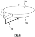
- the adaptation means 11 consists of a horn 12 movable in rotation between two metal plates 13a and 13b parallel to the radiating plate 16.
- the horn 12 shown in FIG. Figure 3 is rotatable about the z 'axis (parallel or confounded with the axis z) extending in a direction normal to the plane xy.
- the mobility of the horn 12 is provided by a digitally controlled guide 20.
- the horn 12 radiates between the two metal plates 13a, 13b a TEM wave (for electrical-magnetic transverse) whose electric field is perpendicular to the metal plates 13a, 13b.
- a network of monopoles 14 is fixed on the upper metal plate 13a in order to capture the TEM wave.
- the rear of the monopole network 14 is closed by a metal reflector 15 located at approximately 1 ⁇ 4 wavelength in order to close the adaptation means.
- Each monopole of the network 14 is connected to each radiating line 17 of the radiating plate 16 by means of a coaxial cable 18.
- the coaxial cables 18 are all of different lengths and introduce the delay necessary for the focusing of the radiated wave by the radiant plate 16. They also introduce an additional delay making it possible to obtain an initial fixed pointing so that the total score varies from 0 ° to 60 ° for a symmetrical displacement of the horn 12.
- the invention thus makes it possible to point all the directions contained in the 60 ° half-angle cone centered on the axis z by means of a rotation of the horn 12 of ⁇ 30 ° approximately around the axis z 'and a rotation of the antenna assembly 360 ° about the z axis.
- This antenna structure operates in a very wide band of frequencies because the mobile horn 12 provides a score independent of the frequency.
Landscapes
- Physics & Mathematics (AREA)
- Engineering & Computer Science (AREA)
- Astronomy & Astrophysics (AREA)
- General Physics & Mathematics (AREA)
- Remote Sensing (AREA)
- Aviation & Aerospace Engineering (AREA)
- Electromagnetism (AREA)
- Aerials With Secondary Devices (AREA)
- Variable-Direction Aerials And Aerial Arrays (AREA)
Claims (10)
- Flachantenne (10) zur Satellitentelekommunikation, umfassend:- eine in einer Ebene strahlende Platine (16), umfassend mindestens eine strahlende Leitung (17) und- ein Anpassungsmittel (11), das in der Lage ist, den Verzug der durch die mindestens eine strahlende Leitung (17) emittierten oder empfangenen Felder zu modifizieren,dadurch gekennzeichnet, dass das Anpassungsmittel (11) Folgendes umfasst:- ein um eine Achse senkrecht zur Ebene rotationsmobiles Horn (12) zwischen den zwei Metallplatten (13a, 13b), die zur Ebene parallel sind und ein Sensorennetz (14) enthalten und- mindestens ein zwischen mindestens einem Netzsensor (14) und der mindestens einen strahlenden Leitung (17) angeschlossenes Koaxialkabel (8),- wobei die Länge des mindestens einen Koaxialkabels (8) zum Einführen eines notwendigen Verzugs der Fokussierung der gestrahlten Welle durch die mindestens eine strahlende Leitung (17) angepasst ist.
- Flachantenne nach Anspruch 1, dadurch gekennzeichnet, dass das Horn (12) in der Lage ist, zwischen den Metallplatten (13a, 13b) eine Welle zu übertragen, deren elektrisches Feld senkrecht zu den Metallplatten (13a, 13b) steht.
- Flachantenne nach Anspruch 1 oder 2, dadurch gekennzeichnet, dass das Anpassungsmittel (11) ebenfalls ein auf mindestens einer Metallplatte (13a, 13b) fixiertes Monopolsensorennetz (14) umfasst, wobei das mindestens eine Koaxialkabel (8) zwischen dem Monopolsensorennetz (14) und der mindestens einen strahlenden Leitung (17) angeschlossen ist.
- Flachantenne nach Anspruch 3, dadurch gekennzeichnet, dass das Monopolsensorennetz (14) eine durch einen Metallreflektor (5) geschlossene Oberfläche umfasst.
- Flachantenne nach Anspruch 4, dadurch gekennzeichnet, dass der Metallreflektor (5) bei 1/4 der Wellenlänge vom Monopolsensorennetz (14) positioniert ist.
- Flachantenne nach einem der Ansprüche 1 bis 5, dadurch gekennzeichnet, dass die Länge des mindestens einen Koaxialkabels (8) angepasst ist, einen zusätzlichen Verzug einzuführen, der es erlaubt, eine anfängliche fixe Ausrichtung auf eine Weise zu erhalten, dass die Gesamtausrichtung für eine symmetrische Verstellung des Horns (12) von 0° bis 60° variiert.
- Flachantenne nach einem der Ansprüche 1 bis 6, dadurch gekennzeichnet, dass die zwei Metallplatten (13a, 13b) in einer Ebene befestigt sind, die parallel zur Ebene der strahlenden Platine (16) ist.
- Flachantenne nach einem der Ansprüche 1 bis 7, dadurch gekennzeichnet, dass die strahlende Platine (16) mehrere strahlende Leitungen (17) umfasst, die um etwa eine halbe Wellenlänge beabstandet sind.
- Flachantenne nach einem der Ansprüche 1 bis 8, dadurch gekennzeichnet, dass die strahlende Platine (16) mehrere strahlende Leitungen (17) umfasst, die aus einer Ausrichtung von strahlenden Elementen wie Dipolen, Patches oder Schlitzen, bestehen.
- Flachantenne nach einem der Ansprüche 1 bis 9, dadurch gekennzeichnet, dass die strahlende Platine (16) mehrere strahlende Leitungen (17) umfasst, die jeweils einen Verteiler mit einem Eingang und mehreren Ausgängen entsprechend der Anzahl an strahlenden Elementen der strahlenden Leitungen umfassen.
Applications Claiming Priority (2)
| Application Number | Priority Date | Filing Date | Title |
|---|---|---|---|
| FR1455391A FR3022404B1 (fr) | 2014-06-13 | 2014-06-13 | Antenne plate de telecommunication par satellite |
| PCT/EP2015/062681 WO2015189134A1 (fr) | 2014-06-13 | 2015-06-08 | Antenne plate de telecommunication par satellite |
Publications (2)
| Publication Number | Publication Date |
|---|---|
| EP3155689A1 EP3155689A1 (de) | 2017-04-19 |
| EP3155689B1 true EP3155689B1 (de) | 2018-06-06 |
Family
ID=52450219
Family Applications (1)
| Application Number | Title | Priority Date | Filing Date |
|---|---|---|---|
| EP15728822.6A Active EP3155689B1 (de) | 2014-06-13 | 2015-06-08 | Flachantenne zur satellitenkommunikation |
Country Status (5)
| Country | Link |
|---|---|
| US (1) | US10038243B2 (de) |
| EP (1) | EP3155689B1 (de) |
| ES (1) | ES2676907T3 (de) |
| FR (1) | FR3022404B1 (de) |
| WO (1) | WO2015189134A1 (de) |
Families Citing this family (1)
| Publication number | Priority date | Publication date | Assignee | Title |
|---|---|---|---|---|
| CN113193364B (zh) * | 2021-05-17 | 2023-04-14 | 东南大学 | 一种双层扇形旋转结构的低副瓣扫描天线及卫星通信系统 |
Family Cites Families (4)
| Publication number | Priority date | Publication date | Assignee | Title |
|---|---|---|---|---|
| US3170158A (en) | 1963-05-08 | 1965-02-16 | Rotman Walter | Multiple beam radar antenna system |
| US5398035A (en) * | 1992-11-30 | 1995-03-14 | The United States Of America As Represented By The Administrator Of The National Aeronautics And Space Administration | Satellite-tracking millimeter-wave reflector antenna system for mobile satellite-tracking |
| GB0701087D0 (en) | 2007-01-19 | 2007-02-28 | Plasma Antennas Ltd | A displaced feed parallel plate antenna |
| CA2680849A1 (en) * | 2007-03-16 | 2008-09-25 | Mobile Sat Ltd. | A vehicle mounted antenna and methods for transmitting and/or receiving signals |
-
2014
- 2014-06-13 FR FR1455391A patent/FR3022404B1/fr active Active
-
2015
- 2015-06-08 ES ES15728822.6T patent/ES2676907T3/es active Active
- 2015-06-08 US US15/314,083 patent/US10038243B2/en active Active
- 2015-06-08 WO PCT/EP2015/062681 patent/WO2015189134A1/fr not_active Ceased
- 2015-06-08 EP EP15728822.6A patent/EP3155689B1/de active Active
Non-Patent Citations (1)
| Title |
|---|
| None * |
Also Published As
| Publication number | Publication date |
|---|---|
| FR3022404B1 (fr) | 2017-10-13 |
| EP3155689A1 (de) | 2017-04-19 |
| US10038243B2 (en) | 2018-07-31 |
| ES2676907T3 (es) | 2018-07-26 |
| US20170187114A1 (en) | 2017-06-29 |
| FR3022404A1 (fr) | 2015-12-18 |
| WO2015189134A1 (fr) | 2015-12-17 |
Similar Documents
| Publication | Publication Date | Title |
|---|---|---|
| EP2532046B1 (de) | Flachplatten-abtastantenne für landfahrzeuganwendung, fahrzeug mit einer solchen antenne und satellitentelekommunikationssystem mit solch einem fahrzeug | |
| EP0012055B1 (de) | In Streifenleitertechnik ausgeführter Monopulsprimärstrahler und Antenne mit einem solchen Strahler | |
| EP2532050B1 (de) | Bordinterne direktionale flachplattenantenne, fahrzeug mit einer solchen antenne und satellitentelekommunikationssystem mit einem solchen fahrzeug | |
| EP3179551B1 (de) | Kompakteinheit zur doppelpolarisierten ansteuerung für ein strahlungselement einer antenne, und kompaktes netz, das mindestens vier kompakte ansteuerungseinheiten umfasst | |
| EP0462864B1 (de) | Vorrichtung zur Speisung von Strahlungselementen einer Gruppenantenne und ihre Verwendung für eine Antenne eines Landungshilfssystems vom Typ MLS | |
| FR2806214A1 (fr) | Antenne reflectrice comportant une pluralite de panneaux | |
| EP3435480B1 (de) | Antenne mit integrierten verzögerungslinsen im innern eines verteilers auf der basis von wellenleiterteilern mit parallelen platten | |
| EP0707357B1 (de) | Antennensystem mit mehreren Speisesystemen, integriert in einem rauscharmen Umsetzer (LNC) | |
| EP3844844B1 (de) | Antenne zum senden und/oder empfangen einer elektromagnetischen welle und system mit dieser antenne | |
| EP0072316B1 (de) | Antenne mit elektronischer Schwenkung und mehreren Eingängen und Radar mit einer solchen Antenne | |
| EP3155689B1 (de) | Flachantenne zur satellitenkommunikation | |
| FR2814614A1 (fr) | Lentille divergente a dome pour ondes hyperfrequences et antenne comportant une telle lentille | |
| EP3155690B1 (de) | Flachantenne zur satellitenkommunikation | |
| EP1533866B1 (de) | Adaptive Phasengesteuerte Gruppenantenne mit digitaler Keulenformung | |
| EP0020196B1 (de) | Scheibenförmige Mikrowellenmehrelementenantenne mit Speiseanordnung und deren Verwendung bei Radar | |
| EP0762534B1 (de) | Verfahren zur Verbreiterung des Strahlungsdiagramms einer Gruppenantenne mit verteilten Elementen in einem Volumen | |
| EP3365943B1 (de) | Antennenvorrichtung für erfassungshilfe und entsprechendes antennensystem zur überwachung eines sich bewegenden ziels | |
| EP3902059A1 (de) | Breitband-richtantenne mit longitudinalwellen-übertragung | |
| EP4207493B1 (de) | Passive direktionale hf-antenne mit ein- oder zweidimensionaler abtastung | |
| EP2889955B1 (de) | Kompaktantennenstruktur für Telekommunikationen über Satelliten | |
| WO2025163550A1 (fr) | Antenne à source défocalisée | |
| EP3506426B1 (de) | Strahllenkungsvorrichtung für antennensystem, entsprechendes antennensystem und entsprechende plattform | |
| EP3075031B1 (de) | Anordnung von antennenstrukturen für satellitentelekommunikationen | |
| FR2583927A1 (fr) | Antenne reseau pour emission et/ou reception d'ondes electromagnetiques |
Legal Events
| Date | Code | Title | Description |
|---|---|---|---|
| STAA | Information on the status of an ep patent application or granted ep patent |
Free format text: STATUS: THE INTERNATIONAL PUBLICATION HAS BEEN MADE |
|
| PUAI | Public reference made under article 153(3) epc to a published international application that has entered the european phase |
Free format text: ORIGINAL CODE: 0009012 |
|
| STAA | Information on the status of an ep patent application or granted ep patent |
Free format text: STATUS: REQUEST FOR EXAMINATION WAS MADE |
|
| 17P | Request for examination filed |
Effective date: 20161130 |
|
| AK | Designated contracting states |
Kind code of ref document: A1 Designated state(s): AL AT BE BG CH CY CZ DE DK EE ES FI FR GB GR HR HU IE IS IT LI LT LU LV MC MK MT NL NO PL PT RO RS SE SI SK SM TR |
|
| AX | Request for extension of the european patent |
Extension state: BA ME |
|
| DAV | Request for validation of the european patent (deleted) | ||
| DAX | Request for extension of the european patent (deleted) | ||
| GRAP | Despatch of communication of intention to grant a patent |
Free format text: ORIGINAL CODE: EPIDOSNIGR1 |
|
| STAA | Information on the status of an ep patent application or granted ep patent |
Free format text: STATUS: GRANT OF PATENT IS INTENDED |
|
| INTG | Intention to grant announced |
Effective date: 20171222 |
|
| GRAS | Grant fee paid |
Free format text: ORIGINAL CODE: EPIDOSNIGR3 |
|
| GRAA | (expected) grant |
Free format text: ORIGINAL CODE: 0009210 |
|
| STAA | Information on the status of an ep patent application or granted ep patent |
Free format text: STATUS: THE PATENT HAS BEEN GRANTED |
|
| AK | Designated contracting states |
Kind code of ref document: B1 Designated state(s): AL AT BE BG CH CY CZ DE DK EE ES FI FR GB GR HR HU IE IS IT LI LT LU LV MC MK MT NL NO PL PT RO RS SE SI SK SM TR |
|
| REG | Reference to a national code |
Ref country code: GB Ref legal event code: FG4D Free format text: NOT ENGLISH |
|
| REG | Reference to a national code |
Ref country code: CH Ref legal event code: EP Ref country code: AT Ref legal event code: REF Ref document number: 1007063 Country of ref document: AT Kind code of ref document: T Effective date: 20180615 |
|
| REG | Reference to a national code |
Ref country code: IE Ref legal event code: FG4D Free format text: LANGUAGE OF EP DOCUMENT: FRENCH |
|
| REG | Reference to a national code |
Ref country code: FR Ref legal event code: PLFP Year of fee payment: 4 |
|
| REG | Reference to a national code |
Ref country code: DE Ref legal event code: R096 Ref document number: 602015011947 Country of ref document: DE |
|
| REG | Reference to a national code |
Ref country code: NL Ref legal event code: FP |
|
| REG | Reference to a national code |
Ref country code: ES Ref legal event code: FG2A Ref document number: 2676907 Country of ref document: ES Kind code of ref document: T3 Effective date: 20180726 |
|
| REG | Reference to a national code |
Ref country code: LT Ref legal event code: MG4D |
|
| PG25 | Lapsed in a contracting state [announced via postgrant information from national office to epo] |
Ref country code: LT Free format text: LAPSE BECAUSE OF FAILURE TO SUBMIT A TRANSLATION OF THE DESCRIPTION OR TO PAY THE FEE WITHIN THE PRESCRIBED TIME-LIMIT Effective date: 20180606 Ref country code: CY Free format text: LAPSE BECAUSE OF FAILURE TO SUBMIT A TRANSLATION OF THE DESCRIPTION OR TO PAY THE FEE WITHIN THE PRESCRIBED TIME-LIMIT Effective date: 20180606 Ref country code: BG Free format text: LAPSE BECAUSE OF FAILURE TO SUBMIT A TRANSLATION OF THE DESCRIPTION OR TO PAY THE FEE WITHIN THE PRESCRIBED TIME-LIMIT Effective date: 20180906 Ref country code: SE Free format text: LAPSE BECAUSE OF FAILURE TO SUBMIT A TRANSLATION OF THE DESCRIPTION OR TO PAY THE FEE WITHIN THE PRESCRIBED TIME-LIMIT Effective date: 20180606 Ref country code: FI Free format text: LAPSE BECAUSE OF FAILURE TO SUBMIT A TRANSLATION OF THE DESCRIPTION OR TO PAY THE FEE WITHIN THE PRESCRIBED TIME-LIMIT Effective date: 20180606 Ref country code: NO Free format text: LAPSE BECAUSE OF FAILURE TO SUBMIT A TRANSLATION OF THE DESCRIPTION OR TO PAY THE FEE WITHIN THE PRESCRIBED TIME-LIMIT Effective date: 20180906 |
|
| PG25 | Lapsed in a contracting state [announced via postgrant information from national office to epo] |
Ref country code: GR Free format text: LAPSE BECAUSE OF FAILURE TO SUBMIT A TRANSLATION OF THE DESCRIPTION OR TO PAY THE FEE WITHIN THE PRESCRIBED TIME-LIMIT Effective date: 20180907 Ref country code: HR Free format text: LAPSE BECAUSE OF FAILURE TO SUBMIT A TRANSLATION OF THE DESCRIPTION OR TO PAY THE FEE WITHIN THE PRESCRIBED TIME-LIMIT Effective date: 20180606 Ref country code: RS Free format text: LAPSE BECAUSE OF FAILURE TO SUBMIT A TRANSLATION OF THE DESCRIPTION OR TO PAY THE FEE WITHIN THE PRESCRIBED TIME-LIMIT Effective date: 20180606 Ref country code: LV Free format text: LAPSE BECAUSE OF FAILURE TO SUBMIT A TRANSLATION OF THE DESCRIPTION OR TO PAY THE FEE WITHIN THE PRESCRIBED TIME-LIMIT Effective date: 20180606 |
|
| REG | Reference to a national code |
Ref country code: AT Ref legal event code: MK05 Ref document number: 1007063 Country of ref document: AT Kind code of ref document: T Effective date: 20180606 |
|
| PG25 | Lapsed in a contracting state [announced via postgrant information from national office to epo] |
Ref country code: RO Free format text: LAPSE BECAUSE OF FAILURE TO SUBMIT A TRANSLATION OF THE DESCRIPTION OR TO PAY THE FEE WITHIN THE PRESCRIBED TIME-LIMIT Effective date: 20180606 Ref country code: SK Free format text: LAPSE BECAUSE OF FAILURE TO SUBMIT A TRANSLATION OF THE DESCRIPTION OR TO PAY THE FEE WITHIN THE PRESCRIBED TIME-LIMIT Effective date: 20180606 Ref country code: CZ Free format text: LAPSE BECAUSE OF FAILURE TO SUBMIT A TRANSLATION OF THE DESCRIPTION OR TO PAY THE FEE WITHIN THE PRESCRIBED TIME-LIMIT Effective date: 20180606 Ref country code: PL Free format text: LAPSE BECAUSE OF FAILURE TO SUBMIT A TRANSLATION OF THE DESCRIPTION OR TO PAY THE FEE WITHIN THE PRESCRIBED TIME-LIMIT Effective date: 20180606 Ref country code: IS Free format text: LAPSE BECAUSE OF FAILURE TO SUBMIT A TRANSLATION OF THE DESCRIPTION OR TO PAY THE FEE WITHIN THE PRESCRIBED TIME-LIMIT Effective date: 20181006 Ref country code: EE Free format text: LAPSE BECAUSE OF FAILURE TO SUBMIT A TRANSLATION OF THE DESCRIPTION OR TO PAY THE FEE WITHIN THE PRESCRIBED TIME-LIMIT Effective date: 20180606 Ref country code: AT Free format text: LAPSE BECAUSE OF FAILURE TO SUBMIT A TRANSLATION OF THE DESCRIPTION OR TO PAY THE FEE WITHIN THE PRESCRIBED TIME-LIMIT Effective date: 20180606 |
|
| PG25 | Lapsed in a contracting state [announced via postgrant information from national office to epo] |
Ref country code: SM Free format text: LAPSE BECAUSE OF FAILURE TO SUBMIT A TRANSLATION OF THE DESCRIPTION OR TO PAY THE FEE WITHIN THE PRESCRIBED TIME-LIMIT Effective date: 20180606 |
|
| REG | Reference to a national code |
Ref country code: DE Ref legal event code: R097 Ref document number: 602015011947 Country of ref document: DE |
|
| REG | Reference to a national code |
Ref country code: IE Ref legal event code: MM4A |
|
| PG25 | Lapsed in a contracting state [announced via postgrant information from national office to epo] |
Ref country code: MC Free format text: LAPSE BECAUSE OF FAILURE TO SUBMIT A TRANSLATION OF THE DESCRIPTION OR TO PAY THE FEE WITHIN THE PRESCRIBED TIME-LIMIT Effective date: 20180606 Ref country code: LU Free format text: LAPSE BECAUSE OF NON-PAYMENT OF DUE FEES Effective date: 20180608 |
|
| PLBE | No opposition filed within time limit |
Free format text: ORIGINAL CODE: 0009261 |
|
| STAA | Information on the status of an ep patent application or granted ep patent |
Free format text: STATUS: NO OPPOSITION FILED WITHIN TIME LIMIT |
|
| PG25 | Lapsed in a contracting state [announced via postgrant information from national office to epo] |
Ref country code: IE Free format text: LAPSE BECAUSE OF NON-PAYMENT OF DUE FEES Effective date: 20180608 |
|
| 26N | No opposition filed |
Effective date: 20190307 |
|
| PG25 | Lapsed in a contracting state [announced via postgrant information from national office to epo] |
Ref country code: DK Free format text: LAPSE BECAUSE OF FAILURE TO SUBMIT A TRANSLATION OF THE DESCRIPTION OR TO PAY THE FEE WITHIN THE PRESCRIBED TIME-LIMIT Effective date: 20180606 Ref country code: SI Free format text: LAPSE BECAUSE OF FAILURE TO SUBMIT A TRANSLATION OF THE DESCRIPTION OR TO PAY THE FEE WITHIN THE PRESCRIBED TIME-LIMIT Effective date: 20180606 |
|
| PG25 | Lapsed in a contracting state [announced via postgrant information from national office to epo] |
Ref country code: AL Free format text: LAPSE BECAUSE OF FAILURE TO SUBMIT A TRANSLATION OF THE DESCRIPTION OR TO PAY THE FEE WITHIN THE PRESCRIBED TIME-LIMIT Effective date: 20180606 |
|
| PG25 | Lapsed in a contracting state [announced via postgrant information from national office to epo] |
Ref country code: MT Free format text: LAPSE BECAUSE OF FAILURE TO SUBMIT A TRANSLATION OF THE DESCRIPTION OR TO PAY THE FEE WITHIN THE PRESCRIBED TIME-LIMIT Effective date: 20180606 |
|
| PG25 | Lapsed in a contracting state [announced via postgrant information from national office to epo] |
Ref country code: TR Free format text: LAPSE BECAUSE OF FAILURE TO SUBMIT A TRANSLATION OF THE DESCRIPTION OR TO PAY THE FEE WITHIN THE PRESCRIBED TIME-LIMIT Effective date: 20180606 |
|
| PG25 | Lapsed in a contracting state [announced via postgrant information from national office to epo] |
Ref country code: PT Free format text: LAPSE BECAUSE OF FAILURE TO SUBMIT A TRANSLATION OF THE DESCRIPTION OR TO PAY THE FEE WITHIN THE PRESCRIBED TIME-LIMIT Effective date: 20180606 |
|
| PG25 | Lapsed in a contracting state [announced via postgrant information from national office to epo] |
Ref country code: HU Free format text: LAPSE BECAUSE OF FAILURE TO SUBMIT A TRANSLATION OF THE DESCRIPTION OR TO PAY THE FEE WITHIN THE PRESCRIBED TIME-LIMIT; INVALID AB INITIO Effective date: 20150608 Ref country code: MK Free format text: LAPSE BECAUSE OF NON-PAYMENT OF DUE FEES Effective date: 20180606 |
|
| PGFP | Annual fee paid to national office [announced via postgrant information from national office to epo] |
Ref country code: DE Payment date: 20250617 Year of fee payment: 11 |
|
| PGFP | Annual fee paid to national office [announced via postgrant information from national office to epo] |
Ref country code: GB Payment date: 20250625 Year of fee payment: 11 |
|
| PGFP | Annual fee paid to national office [announced via postgrant information from national office to epo] |
Ref country code: NL Payment date: 20250630 Year of fee payment: 11 Ref country code: BE Payment date: 20250625 Year of fee payment: 11 |
|
| PGFP | Annual fee paid to national office [announced via postgrant information from national office to epo] |
Ref country code: FR Payment date: 20250526 Year of fee payment: 11 |
|
| PGFP | Annual fee paid to national office [announced via postgrant information from national office to epo] |
Ref country code: ES Payment date: 20250710 Year of fee payment: 11 |
|
| PGFP | Annual fee paid to national office [announced via postgrant information from national office to epo] |
Ref country code: IT Payment date: 20250606 Year of fee payment: 11 |
|
| PGFP | Annual fee paid to national office [announced via postgrant information from national office to epo] |
Ref country code: CH Payment date: 20250701 Year of fee payment: 11 |