EP3156139A1 - Verfahren zur reinigung einer befestigungsfläche für ein ausgleichselement an einem fahrzeugrad - Google Patents
Verfahren zur reinigung einer befestigungsfläche für ein ausgleichselement an einem fahrzeugrad Download PDFInfo
- Publication number
- EP3156139A1 EP3156139A1 EP16192696.9A EP16192696A EP3156139A1 EP 3156139 A1 EP3156139 A1 EP 3156139A1 EP 16192696 A EP16192696 A EP 16192696A EP 3156139 A1 EP3156139 A1 EP 3156139A1
- Authority
- EP
- European Patent Office
- Prior art keywords
- cleaning
- cleaning device
- rim
- handling device
- wetting
- Prior art date
- Legal status (The legal status is an assumption and is not a legal conclusion. Google has not performed a legal analysis and makes no representation as to the accuracy of the status listed.)
- Granted
Links
Images

Classifications
-
- B—PERFORMING OPERATIONS; TRANSPORTING
- B08—CLEANING
- B08B—CLEANING IN GENERAL; PREVENTION OF FOULING IN GENERAL
- B08B1/00—Cleaning by methods involving the use of tools
- B08B1/30—Cleaning by methods involving the use of tools by movement of cleaning members over a surface
- B08B1/32—Cleaning by methods involving the use of tools by movement of cleaning members over a surface using rotary cleaning members
-
- B—PERFORMING OPERATIONS; TRANSPORTING
- B08—CLEANING
- B08B—CLEANING IN GENERAL; PREVENTION OF FOULING IN GENERAL
- B08B3/00—Cleaning by methods involving the use or presence of liquid or steam
- B08B3/04—Cleaning involving contact with liquid
-
- B—PERFORMING OPERATIONS; TRANSPORTING
- B08—CLEANING
- B08B—CLEANING IN GENERAL; PREVENTION OF FOULING IN GENERAL
- B08B1/00—Cleaning by methods involving the use of tools
- B08B1/10—Cleaning by methods involving the use of tools characterised by the type of cleaning tool
- B08B1/12—Brushes
-
- B—PERFORMING OPERATIONS; TRANSPORTING
- B08—CLEANING
- B08B—CLEANING IN GENERAL; PREVENTION OF FOULING IN GENERAL
- B08B1/00—Cleaning by methods involving the use of tools
- B08B1/30—Cleaning by methods involving the use of tools by movement of cleaning members over a surface
- B08B1/32—Cleaning by methods involving the use of tools by movement of cleaning members over a surface using rotary cleaning members
- B08B1/34—Cleaning by methods involving the use of tools by movement of cleaning members over a surface using rotary cleaning members rotating about an axis parallel to the surface
-
- B—PERFORMING OPERATIONS; TRANSPORTING
- B08—CLEANING
- B08B—CLEANING IN GENERAL; PREVENTION OF FOULING IN GENERAL
- B08B3/00—Cleaning by methods involving the use or presence of liquid or steam
- B08B3/04—Cleaning involving contact with liquid
- B08B3/08—Cleaning involving contact with liquid the liquid having chemical or dissolving effect
-
- B—PERFORMING OPERATIONS; TRANSPORTING
- B60—VEHICLES IN GENERAL
- B60B—VEHICLE WHEELS; CASTORS; AXLES FOR WHEELS OR CASTORS; INCREASING WHEEL ADHESION
- B60B1/00—Spoked wheels; Spokes thereof
-
- B—PERFORMING OPERATIONS; TRANSPORTING
- B60—VEHICLES IN GENERAL
- B60S—SERVICING, CLEANING, REPAIRING, SUPPORTING, LIFTING, OR MANOEUVRING OF VEHICLES, NOT OTHERWISE PROVIDED FOR
- B60S3/00—Vehicle cleaning apparatus not integral with vehicles
- B60S3/04—Vehicle cleaning apparatus not integral with vehicles for exteriors of land vehicles
- B60S3/042—Wheel cleaning devices
-
- B—PERFORMING OPERATIONS; TRANSPORTING
- B60—VEHICLES IN GENERAL
- B60B—VEHICLE WHEELS; CASTORS; AXLES FOR WHEELS OR CASTORS; INCREASING WHEEL ADHESION
- B60B3/00—Disc wheels, i.e. wheels with load-supporting disc body
-
- F—MECHANICAL ENGINEERING; LIGHTING; HEATING; WEAPONS; BLASTING
- F16—ENGINEERING ELEMENTS AND UNITS; GENERAL MEASURES FOR PRODUCING AND MAINTAINING EFFECTIVE FUNCTIONING OF MACHINES OR INSTALLATIONS; THERMAL INSULATION IN GENERAL
- F16F—SPRINGS; SHOCK-ABSORBERS; MEANS FOR DAMPING VIBRATION
- F16F15/00—Suppression of vibrations in systems; Means or arrangements for avoiding or reducing out-of-balance forces, e.g. due to motion
- F16F15/32—Correcting- or balancing-weights or equivalent means for balancing rotating bodies, e.g. vehicle wheels
- F16F15/324—Correcting- or balancing-weights or equivalent means for balancing rotating bodies, e.g. vehicle wheels the rotating body being a vehicle wheel
-
- G—PHYSICS
- G01—MEASURING; TESTING
- G01M—TESTING STATIC OR DYNAMIC BALANCE OF MACHINES OR STRUCTURES; TESTING OF STRUCTURES OR APPARATUS, NOT OTHERWISE PROVIDED FOR
- G01M1/00—Testing static or dynamic balance of machines or structures
- G01M1/30—Compensating imbalance
- G01M1/32—Compensating imbalance by adding material to the body to be tested, e.g. by correcting-weights
- G01M1/326—Compensating imbalance by adding material to the body to be tested, e.g. by correcting-weights the body being a vehicle wheel
Definitions
- the invention relates to a method for cleaning a mounting surface for a compensation element on an inner side of a rim of a wheel. Furthermore, the invention relates to a device for carrying out the method.
- the surface to which the compensating element is to be attached must be cleaned prior to its attachment. Even small amounts of dirt can affect the liability of the fastener.
- the invention is thus based on the object of providing an automatable cleaning of a region of a rim.
- a method for cleaning a mounting surface for a compensation element on an inner side of a rim of a vehicle wheel in which the vehicle is positioned in a holding device such that a cleaning device by means of a handling device to the mounting surface on the Inside the rim of the positioned vehicle wheel is movable, wherein the cleaning device is arranged at a free end of the handling device and the cleaning device is moved from the handling device to a wetting agent filled with a cleaning agent and wetted in the wetting device with cleaning agent, and the detergent-wetted cleaning device of the handling device in the rim and there is moved so that the cleaning device cleans at least one mounting surface on the inside of the rim.
- the method according to the invention can be automated and can be integrated into an assembly line.
- the cleaning is reproducible and can be done with a fixed amount of detergent.
- a small amount of cleaning agent is used for cleaning, so that it is also ensured that the cleaning agent substantially completely evaporates until the compensation element is attached. This can an impairment of the fastener by the cleaning agent are almost excluded.
- an upper side of the cleaning device is immersed in a wetting setting of the wetting device having the cleaning agent.
- the immersion depth of the cleaning device can be set and controlled and varied depending on the cleaning agent used, the shape of the cleaning device and the number of mounting surfaces to be cleaned. Due to the low immersion depth, only a small amount of cleaning agent is absorbed, wherein the cleaning agent is distributed by the movement of the handling device in the cleaning device, so that finally an efficient cleaning of the mounting surface is ensured with detergent.
- the inventive method combines a mechanical cleaning with a chemical cleaning, resulting in an improved and more efficient cleaning.
- the mechanical cleaning can also be supported by the fact that the cleaning device rotates cleaning the mounting surface.
- a drive may be provided in the housing of the handling device, which is drivingly connected to the cleaning device.
- a compressed air motor or an electric motor can be used as a drive.
- the rotation of the cleaning device can be controlled time-dependent, so that the cleaning of the mounting surface or the rotation of the cleaning device takes place for a defined period of time and then the engine shuts off.
- the cleaning device can be moved with the help of the handling device in the rim in three spatial directions, wherein after the start of the mounting surface, the actual cleaning takes place in two spatial directions, so that the cleaning device is moved in particular laterally to the inside of the rim.
- the handling device moves the cleaning device after cleaning a first attachment surface to a second attachment surface to be cleaned.
- the invention relates to a device for carrying out the method with a holder holding a vehicle and a handling device having at its free end a rotatable cleaning device, wherein the wheel is positioned in the holding device such that at least one to be cleaned mounting surface an inside of a rim of the wheel is accessible to the cleaning device movable by the handling device here, and wherein a wetting device having a cleaning agent is arranged in the working area of the handling device.
- the inventive device can be integrated by the automatically performed cleaning of the mounting surface as a cleaning station in an assembly line. This cleaning station, for example, downstream of an unbalance measuring station and the balancing station can be connected upstream.
- several mounting surfaces can be cleaned in one step.
- a mechanical and chemical cleaning a fast and above all efficient cleaning of the mounting surface can be achieved, which in turn allows a secure and permanent attachment of the compensation element.
- the handling device is designed as a joint arm movable in three directions.
- the cleaning device is moved in the interior of the rim in three spatial directions and the mounting surface is cleaned in two spatial directions.
- the cleaning device is movable relative to the articulated arm of the handling device about at least one axis.
- a precise control of the cleaning device in the rim is possible.
- the freedom of movement of the cleaning device is improved relative to the articulated arm.
- the cleaning device can advantageously be brought into rotation by a motor arranged on the handling device.
- the motor may be housed in the housing of the handling device.
- the handling device can be controlled differently.
- a sensor for detecting markings on the wheel is arranged on the handling device.
- a mounting surface, to which a compensation element is to be attached can be marked in advance, and detected by the sensor of the handling device and used to control the handling device.
- the attachment surface may be detected with a mark set by means of a magnetic dipole in the imbalance measurement station via a magnetic field sensor present on the handling device.
- the movements of the handling device can be controlled by means of a programmable servo control, for example a CNC control, so that the respective device of the handling device can be easily adapted to the intended application by the input of application-specific data and programs.
- the Control device of the handling device can receive the position of the fixing surface to be cleaned from the unbalance measuring station and control the handling device accordingly.
- the wetting device comprises a wetting agent having the cleaning agent, the diameter of which is adapted to the diameter of the cleaning device, so that an upper side of the cleaning device can be brought completely into contact with the wetting plate.
- the depth of the wetting actuator can be adjusted such that only a defined region of the cleaning device is immersed in the wetting actuator.
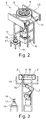
- a device 1 for cleaning an attachment surface 2 for a compensation element on an inner side 3 of a rim 4 of a wheel 5, which can be used for a previously described method, is shown.
- the handling device 6 is an industrial robot with an articulated arm 7 having a plurality of axes of movement, by means of which the handling device 6 can be moved in three spatial directions.
- the articulated arm 7 has several joints.
- the handling device 6 may be stationarily positioned on a stand 8. However, it is also a mobile one Positioning of the handling device 6 possible, in which the handling device 6 is arranged on a sliding on rails stand.
- the handling device 6 has a cleaning device 9, which is designed as a brush and rotatably connected to a drive shaft of a motor 10.
- the cleaning device 9 has a cylindrical shape and has a curvature of the rim inside 3 adapted diameter.
- the cleaning device 9 can be easily adapted to different surfaces to be cleaned.
- a material for the cleaning device 9 is a hydrophilic plastic material that receives a cleaning agent 11 well and the surface of the rim 4 is not damaged.
- the cleaning device 9 is driven by the arranged in the housing of the handling device 6 motor 10 and set in rotation.
- the motor 10 may be, for example, a pneumatic motor that drives the cleaning device 9 powerful and is insensitive to the cleaning agent 11 used.
- compressed air motors are in particular a pneumatic blade motor or a gear motor in question.
- the cleaning device 9 can also be driven by means of an electric motor.
- a plurality of independent drives can be used, which can be controlled by a programmable control device and enable a positionally accurate movement of the handling device 6.
- the cleaning device 9 can be movable relative to the articulated arm 7 of the handling device 6 about at least one axis. As a result, a precise movement of the cleaning device 9 in the rim 4 or a rim bowl 12 of the rim 4 is sometimes possible.
- a holding device 13 which serves for the supply and positioning of mounted vehicle wheels 5, in which a compensation of a detected imbalance is to take place.
- the holding device 13 comprises a transport device 14 indicated in the drawing, with the aid of which the vehicle wheel 5 is conveyed to a position above the handling device 6.
- the vehicle wheel 5 is located on the transport device 14 or the holding device 13 such that the rim 4 is oriented towards the handling device 6 and accessible thereto.
- the holding device 13 may also be oriented in a different orientation to the handling device 6 than shown in the drawing, it being only crucial that the rim 4, in particular the rim inside 3 of the rim 4, is accessible to the handling device 6 and the cleaning device 9 can be moved into this.
- a wetting device 15 is located in the working region of the handling device 6.
- the wetting device 15 comprises a trough configured as wetting plate 16.
- liquid cleaning agent 11 is conveyed into the wetting actuator 16 by means of a pump arranged below the wetting actuator 16.
- the cleaning agent 11 may be, for example, isopropanol or alcohol.
- the cleaning agent 11 comprises a bonding agent, which assists the subsequent attachment of the compensating element by the fastening means.
- the bonding agent can be added to the cleaning agent 11 in liquid or solid form, wherein after cleaning the mounting surface 4, the highly volatile cleaning agent 11 evaporates and only the bonding agent remains on the mounting surface 4.
- the device 1 can be part of an assembly line as a cleaning station. Before one or more compensation elements are attached to compensate for the imbalance on the wheel 5, the respective mounting surface 2 is cleaned.
- the vehicle wheel 5 passes through the transport device 14, for example, a conveyor belt, from the unbalance measurement station to the holding device 13.
- a sensor in the form of a light barrier detects when the wheel 5 enters the holding device 13.
- the wheel 5 is positioned in the holding device 13 such that the interior of the rim 4 is accessible to the cleaning device 9 and the cleaning device 9 can clean one or more regions of the rim inside 3.
- the cleaning device 9 can be moved from the handling device 6 to the wetting device 15.
- the cleaning device 9 is moved with an upper side 18 into the wetting actuator 16 so that at least one area of the cleaning device 9 is brought into contact with the cleaning agent 11.
- the cleaning agent 11 is distributed in the cleaning device 9.
- the handling device 6 now moves the cleaning device 9 in the direction of the rim 4, or the rim bowl 12 and into it, up to the attachment surface 2, to which a compensation element is to be glued in the subsequent compensation station.
- the arranged in the holding device 13 vehicle 5 is brought by the servo motor of the holding device 13 in a defined position, wherein the handling device 6 is moved by the control device to be cleaned to the mounting surfaces 2.
- the exact position of the Mounting surface 2 is previously determined in the unbalance measuring station and can thus be used below to control the handling device 6.
- the cleaning device 9 is driven from below into the interior of the rim 4 and moved to the mounting surface 2. By the motor 10, the cleaning device 9 can be set in rotation.
- the cleaning device 9 is aligned tangentially to the rim inside 3.
- the cleaning device 9 can be moved by the handling device 6 laterally to the rim inner side 3, wherein a two-dimensional movement of the cleaning device 9 during the actual cleaning is possible, which is also achieved in that the cleaning device 9 relative to the articulated arm 7 of the handling device 6 is movable about at least one axis.
- the attachment surface 2 can be cleaned efficiently by the cleaning device 9.
- the cleaning is done mechanically by the rotation of the cleaning device 9 and chemically by the cleaning agent 11.
- the cleaning agent 11 evaporates quickly and has no adverse effect on the attachment process of the compensation element.
- the cleaning device 9 can be moved directly after completion of the cleaning of a first attachment surface 2 of the handling device 6 to another mounting surface 2, without the cleaning device 9 would have to be wetted again in the meantime with detergent 11. As a result, a plurality of mounting surfaces 2 can be cleaned in one operation, which brings a considerable time savings.
Landscapes
- Engineering & Computer Science (AREA)
- Mechanical Engineering (AREA)
- Chemical & Material Sciences (AREA)
- Chemical Kinetics & Catalysis (AREA)
- General Chemical & Material Sciences (AREA)
- Cleaning By Liquid Or Steam (AREA)
- Cleaning In General (AREA)
- Automobile Manufacture Line, Endless Track Vehicle, Trailer (AREA)
Abstract
Description
- Die Erfindung betrifft ein Verfahren zur Reinigung einer Befestigungsfläche für ein Ausgleichselement auf einer Innenseite einer Felge eines Rads. Ferner betrifft die Erfindung eine Vorrichtung zur Durchführung des Verfahrens.
- Es sind Verfahren und Vorrichtungen zur Anbringung von Ausgleichselementen an Fahrzeugrädern bekannt. Nach Montage des Fahrzeugrads wird in einer Unwuchtmessvorrichtung die Unwucht des Rads bestimmt. Um die gemessene Unwucht auszugleichen, wird in einer Ausgleichsstation mindestens ein Ausgleichselement an der Innenseite der Felge angebracht. Oftmals ist die Anbringung von mehreren Ausgleichselementen in unterschiedlichen Ausgleichsebenen notwendig. Das anzubringende Ausgleichselement wird in der Regel von einem Materialband abgetrennt, mit einem Befestigungsmittel, z. B. einem Doppelklebeband, beschichtet und an eine zuvor errechnete Position an der Felgeninnenseite geklebt.
- Um eine dauerhafte Befestigung des Ausgleichselements sicherzustellen, muss vor dessen Anbringung die Fläche, an der das Ausgleichselement befestigt werden soll, gereinigt werden. Schon geringe Mengen Schmutz können die Haftbarkeit des Befestigungsmittels beeinflussen.
- Es ist bekannt, die Befestigungsfläche vor Anbringung des Ausgleichselements manuell zu reinigen, indem die Felgeninnenseite mit einem Reinigungstuch ausgewischt wird. Zusätzlich kann ein leicht flüchtiges Reinigungsmittel wie beispielsweise Isopropanol oder Spiritus verwendet werden, um die Reinigungswirkung zu verbessern.
- Nachteilig hierbei ist jedoch, dass eine reproduzierbare Reinigung der Felgen nicht sichergestellt werden kann und auch die verwendete Menge an Reinigungsmittel stark variieren kann. Außerdem ist die bekannte Reinigungsart nicht in einen vollautomatischen Unwuchtausgleichsprozess integrierbar.
- Der Erfindung liegt somit die Aufgabe zugrunde, eine automatisierbare Reinigung eines Bereichs einer Felge bereitzustellen.
- Die Aufgabe wird erfindungsgemäß durch ein Verfahren mit den in Anspruch 1 angegebenen Merkmalen und durch eine Vorrichtung gemäß des Anspruchs 6 gelöst. Vorteilhafte Ausgestaltungen des Verfahrens und der Vorrichtung sind in den Unteransprüchen angegeben.
- Die Aufgabe wird erfindungsgemäß dadurch gelöst, dass ein Verfahren zur Reinigung einer Befestigungsfläche für ein Ausgleichselement auf einer Innenseite einer Felge eines Fahrzeugrads bereitgestellt wird, bei welchem das Fahrzeugrad derart in einer Haltevorrichtung positioniert wird, dass eine Reinigungsvorrichtung mit Hilfe einer Handhabungsvorrichtung zu der Befestigungsfläche an der Innenseite der Felge des positionierten Fahrzeugrads bewegbar ist, wobei die Reinigungsvorrichtung an einem freien Ende der Handhabungsvorrichtung angeordnet ist und die Reinigungsvorrichtung von der Handhabungsvorrichtung zu einer mit einem Reinigungsmittel gefüllten Benetzungseinrichtung bewegt und in der Benetzungseinrichtung mit Reinigungsmittel benetzt wird, und die mit Reinigungsmittel benetzte Reinigungsvorrichtung von der Handhabungsvorrichtung in die Felge und dort derart bewegt wird, dass die Reinigungsvorrichtung mindestens eine Befestigungsfläche auf der Innenseite der Felge reinigt. Das erfindungsgemäße Verfahren ist automatisierbar und kann in eine Montagelinie integriert werden. Außerdem ist die Reinigung reproduzierbar und kann mit einer festgelegten Menge Reinigungsmittel erfolgen. Durch die erfindungsgemäße Reinigung der Befestigungsfläche wird zur Reinigung eine geringe Menge Reinigungsmittel verwendet, so dass auch sichergestellt ist, dass das Reinigungsmittel bis zur Anbringung des Ausgleichselements im Wesentlichen vollständig verdunstet. Hierdurch kann eine Beeinträchtigung des Befestigungsmittels durch das Reinigungsmittel nahezu ausgeschlossen werden.
- Um die von der Reinigungsvorrichtung aufgenommene Menge an Reinigungsmittel möglichst gering zu halten, wird vorgeschlagen, dass eine Oberseite der Reinigungsvorrichtung in einen das Reinigungsmittel aufweisenden Benetzungsteller der Benetzungseinrichtung eingetaucht wird. Die Eintauchtiefe der Reinigungsvorrichtung kann festgelegt und gesteuert werden und in Abhängigkeit von dem verwendeten Reinigungsmittel, der Form der Reinigungsvorrichtung und der Anzahl der zu reinigenden Befestigungsflächen variiert werden. Durch die geringe Eintauchtiefe wird lediglich eine geringe Menge an Reinigungsmittel aufgenommen, wobei das Reinigungsmittel durch die Bewegung der Handhabungsvorrichtung in der Reinigungsvorrichtung verteilt wird, so dass schließlich eine effiziente Reinigung der Befestigungsfläche mit Reinigungsmittel sichergestellt ist.
- Das erfindungsgemäße Verfahren kombiniert eine mechanische Reinigung mit einer chemischen Reinigung, was zu einer verbesserten und effizienteren Reinigung führt. Die mechanische Reinigung kann zudem noch dadurch unterstützt werden, dass die Reinigungsvorrichtung die Befestigungsfläche rotierend reinigt. Hierfür kann im Gehäuse der Handhabungsvorrichtung ein Antrieb vorgesehen sein, der mit der Reinigungsvorrichtung treibend verbunden ist. Als Antrieb kann ein Druckluftmotor oder ein Elektromotor verwendet werden. Die Rotation der Reinigungsvorrichtung kann zeitabhängig gesteuert sein, so dass die Reinigung der Befestigungsfläche bzw. die Rotation der Reinigungsvorrichtung für eine definierte Zeitdauer erfolgt und danach der Motor abschaltet.
- Die Reinigungsvorrichtung kann mit Hilfe der Handhabungsvorrichtung in der Felge in drei Raumrichtungen bewegt werden, wobei nach dem Anfahren der Befestigungsfläche die eigentliche Reinigung in zwei Raumrichtungen erfolgt, so dass die Reinigungsvorrichtung insbesondere lateral zu der Innenseite der Felge bewegt wird.
- In einer bevorzugten Ausgestaltung ist vorgesehen, dass die Handhabungsvorrichtung die Reinigungsvorrichtung nach der Reinigung einer ersten Befestigungsfläche zu einer zweiten zu reinigenden Befestigungsfläche bewegt. Durch einmaliges Einfahren der Reinigungsvorrichtung in den Innenraum der Felge können mehrere Befestigungsflächen gereinigt werden, ohne dass die Reinigungsvorrichtung zwischen den Reinigungen erneut zu der Benetzungseinrichtung gefahren werden muss. Hierdurch können mit geringem Zeitaufwand und in einem Arbeitsschritt mehrere Befestigungsflächen in einem Fahrzeugrad gereinigt werden.
- In einem weiteren Aspekt betrifft die Erfindung eine Vorrichtung zur Durchführung des Verfahrens mit einer ein Fahrzeugrad haltenden Haltevorrichtung und einer Handhabungsvorrichtung, die an ihrem freien Ende eine rotierbare Reinigungsvorrichtung aufweist, wobei das Rad derart in der Haltevorrichtung positionierbar ist, dass mindestens eine zu reinigende Befestigungsfläche an einer Innenseite einer Felge des Rads für die durch die Handhabungsvorrichtung hierhin bewegbare Reinigungsvorrichtung zugänglich ist und wobei eine ein Reinigungsmittel aufweisende Benetzungseinrichtung im Arbeitsbereich der Handhabungsvorrichtung angeordnet ist. Die erfindungsgemäße Vorrichtung kann durch die automatisch ausgeführte Reinigung der Befestigungsfläche als Reinigungsstation in eine Montagelinie integriert werden. Diese Reinigungsstation kann beispielsweise einer Unwuchtmessstation nachgeschaltet und der Ausgleichsstation vorgeschaltet sein. Außerdem können auch mehrere Befestigungsflächen in einem Arbeitsschritt gereinigt werden. Insbesondere durch die Kombination einer mechanischen und chemischen Reinigung kann eine schnelle und vor allem effiziente Reinigung der Befestigungsfläche erreicht werden, was wiederum eine sichere und dauerhafte Befestigung des Ausgleichselements ermöglicht.
- Um die Reinigungsvorrichtung in allen drei Raumrichtungen beweglich zu gestalten, wird vorgeschlagen, dass die Handhabungsvorrichtung als ein in drei Richtungen bewegbarer Gelenkarm ausgestaltet ist. Hierdurch ist es auch möglich, dass die Reinigungsvorrichtung im Inneren der Felge in drei Raumrichtungen bewegt wird und die Befestigungsfläche in zwei Raumrichtungen gereinigt wird.
- Vorteilhafterweise ist die Reinigungsvorrichtung relativ zum Gelenkarm der Handhabungsvorrichtung um wenigstens eine Achse bewegbar. Hierdurch ist eine genaue Steuerung der Reinigungsvorrichtung in der Felge möglich. Zudem ist die Bewegungsfreiheit der Reinigungsvorrichtung relativ zu dem Gelenkarm verbessert.
- Die Reinigungsvorrichtung ist vorteilhafterweise durch einen an der Handhabungsvorrichtung angeordneten Motor in Rotation bringbar. Der Motor kann in dem Gehäuse der Handhabungsvorrichtung untergebracht sein.
- Die Handhabungsvorrichtung kann unterschiedlich gesteuert sein. So kann es beispielsweise vorteilhaft sein, dass an der Handhabungsvorrichtung ein Sensor zur Erfassung von Markierungen an dem Rad angeordnet ist. Eine Befestigungsfläche, an die ein Ausgleichselement angebracht werden soll, kann zuvor markiert, und von dem Sensor der Handhabungsvorrichtung erfasst und zur Ansteuerung der Handhabungsvorrichtung verwendet werden. Beispielsweise kann die Befestigungsfläche mit einer Marke, die mithilfe eines magnetischen Dipols in der Unwuchtmessstation gesetzt wird, über einen an der Handhabungsvorrichtung vorhandenen Magnetfeldsensor detektiert werden. Die Bewegungen der Handhabungsvorrichtung können mittels einer programmierbaren Servosteuerung, beispielsweise einer CNC-Steuerung, gesteuert werden, so dass durch die Eingabe anwendungsspezifischer Daten und Programme die jeweilige Einrichtung der Handhabungsvorrichtung auf die vorgesehene Anwendung auf einfache Weise erfolgen kann. Die Steuereinrichtung der Handhabungsvorrichtung kann die Position der zu reinigenden Befestigungsfläche von der Unwuchtmessstation erhalten und dementsprechend die Handhabungsvorrichtung steuern.
- Es wird ferner vorgeschlagen, dass die Benetzungseinrichtung einen das Reinigungsmittel aufweisenden Benetzungsteller umfasst, dessen Durchmesser an den Durchmesser der Reinigungsvorrichtung angepasst ist, so dass eine Oberseite der Reinigungsvorrichtung vollständig zur Auflage in den Benetzungsteller bringbar ist. Ferner kann die Tiefe des Benetzungsteller derart angepasst werden, dass lediglich ein definierter Bereich der Reinigungsvorrichtung in den Benetzungsteller eintaucht. Selbstverständlich ist es ferner möglich, die Eintauchtiefe über die Steuereinrichtung der Handhabungsvorrichtung zu steuern.
- Die Erfindung wird nachfolgend anhand eines Ausführungsbeispiels der Erfindung näher erläutert, das in der Zeichnung dargestellt ist. Es zeigen
- Figur 1
- eine perspektivische Ansicht einer bevorzugten Vorrichtung mit einer Reinigungsvorrichtung an der Benetzungseinrichtung,
- Figur 2
- eine perspektivische Ansicht der bevorzugten Vorrichtung mit der Reinigungsvorrichtung in einer Felge und
- Figur 3
- eine Seitenansicht der Vorrichtung gemäß
Figur 2 , teilweise im Querschnitt. - Es ist eine Vorrichtung 1 zur Reinigung einer Befestigungsfläche 2 für ein Ausgleichselement auf einer Innenseite 3 einer Felge 4 eines Rads 5 dargestellt, die für ein zuvor beschriebenes Verfahren verwendbar ist. Bei der Handhabungsvorrichtung 6 handelt es sich um einen Industrieroboter, mit einem mehrere Bewegungsachsen aufweisenden Gelenkarm 7, durch den die Handhabungsvorrichtung 6 in drei Raumrichtungen bewegbar ist. Der Gelenkarm 7 weist mehrere Gelenke auf. Die Handhabungsvorrichtung 6 kann stationär auf einem Standfuß 8 positioniert sein. Jedoch ist auch eine mobile Positionierung der Handhabungsvorrichtung 6 möglich, bei dem die Handhabungsvorrichtung 6 auf einem auf Schienen verschiebbaren Standfuß angeordnet ist.
- An ihrem freien Ende weist die Handhabungsvorrichtung 6 eine Reinigungsvorrichtung 9 auf, die als Bürste ausgestaltet und drehfest mit einer Antriebswelle eines Motors 10 verbunden ist. Die Reinigungsvorrichtung 9 hat eine zylindrische Form und weist einen der Krümmung der Felgeninnenseite 3 angepassten Durchmesser auf. Die Reinigungsvorrichtung 9 kann beispielsweise über eine Steck- oder Schnappverbindung treibend mit dem Motor 10 verbunden sein und kann einfach ausgewechselt werden. Somit kann die Reinigungsvorrichtung 9 einfach an unterschiedliche zu reinigende Oberflächen angepasst werden. Als Material für die Reinigungsvorrichtung 9 eignet sich ein hydrophiles Kunststoffmaterial, das ein Reinigungsmittel 11 gut aufnimmt und die Oberfläche der Felge 4 nicht beschädigt.
- Die Reinigungsvorrichtung 9 wird durch den im Gehäuse der Handhabungsvorrichtung 6 angeordneten Motor 10 angetrieben und in Rotation versetzt. Der Motor 10 kann zum Beispiel ein Druckluftmotor sein, der die Reinigungsvorrichtung 9 leistungsstark antreibt und gegenüber dem verwendeten Reinigungsmittel 11 unempfindlich ist. Als Druckluftmotoren kommen insbesondere ein Druckluftlamellenmotor oder ein Zahnradmotor in Frage. Selbstverständlich kann die Reinigungsvorrichtung 9 auch mittels einem Elektromotor angetrieben werden.
- Um die Handhabungsvorrichtung 6 genau zu steuern, können mehrere unabhängige Antriebe verwendet werden, die durch eine programmierbare Steuereinrichtung steuerbar sind und eine positionsgenaue Bewegung der Handhabungsvorrichtung 6 ermöglichen. Außerdem kann die Reinigungsvorrichtung 9 relativ zum Gelenkarm 7 der Handhabungsvorrichtung 6 um wenigstens eine Achse bewegbar sein. Hierdurch ist mitunter eine präzise Bewegung der Reinigungsvorrichtung 9 in der Felge 4 beziehungsweise einer Felgenschüssel 12 der Felge 4 möglich.
- Im Arbeitsbereich der Handhabungsvorrichtung 6 ist eine Haltevorrichtung 13 angeordnet, die der Zuführung und Positionierung von montierten Fahrzeugrädern 5 dient, bei denen ein Ausgleich einer festgestellten Unwucht erfolgen soll. Die Haltevorrichtung 13 umfasst eine in der Zeichnung angedeutete Transportvorrichtung 14, mit deren Hilfe das Fahrzeugrad 5 in eine Position oberhalb der Handhabungsvorrichtung 6 befördert wird. Hierbei liegt das Fahrzeugrad 5 so auf der Transportvorrichtung 14 beziehungsweise der Haltevorrichtung 13, dass die Felge 4 zu der Handhabungsvorrichtung 6 hin orientiert und für diese zugänglich ist. Die Haltevorrichtung 13 kann auch in einer anderen Orientierung zu der Handhabungsvorrichtung 6 ausgerichtet sein, als in der Zeichnung dargestellt, wobei lediglich entscheidend ist, dass die Felge 4, insbesondere die Felgeninnenseite 3 der Felge 4, für die Handhabungsvorrichtung 6 zugänglich ist und die Reinigungsvorrichtung 9 in diese bewegt werden kann.
- Weiterhin befindet sich eine Benetzungseinrichtung 15 im Arbeitsbereich der Handhabungsvorrichtung 6. Die Benetzungseinrichtung 15 umfasst eine als Benetzungsteller 16 ausgestaltete Wanne. Durch eine Zuführleitung 17 im Zentrum des Benetzungstellers 16 wird mittels einer unterhalb des Benetzungstellers 16 angeordneten Pumpe flüssiges Reinigungsmittel 11 in den Benetzungsteller 16 befördert. Das Reinigungsmittel 11 kann beispielsweise Isopropanol oder Spiritus sein. Diesbezüglich kann es vorteilhaft sein, wenn das Reinigungsmittel 11 einen Haftvermittler umfasst, der die nachfolgende Anbringung des Ausgleichselements durch das Befestigungsmittel unterstützt. Der Haftvermittler kann dem Reinigungsmittel 11 in flüssiger oder fester Form beigemischt werden, wobei nach der Reinigung der Befestigungsfläche 4 das leicht flüchtige Reinigungsmittel 11 verdunstet und lediglich der Haftvermittler an der Befestigungsfläche 4 zurückbleibt.
- Nachdem das Fahrzeugrad 5 montiert ist, wird die Unwucht des Rads 5 in einer Unwuchtmessstation gemessen. Die erfindungsgemäße Vorrichtung 1 kann als Reinigungsstation Bestandteil einer Montagelinie sein. Bevor ein oder mehrere Ausgleichselemente zum Ausgleich der Unwucht an dem Rad 5 befestigt werden, wird die jeweilige Befestigungsfläche 2 gereinigt. Hierfür gelangt das Fahrzeugrad 5 über die Transportvorrichtung 14, beispielsweise ein Förderband, von der Unwuchtmessstation zu der Haltevorrichtung 13. Ein Sensor in Form einer Lichtschranke erkennt, wann das Rad 5 in die Haltevorrichtung 13 einfährt. Mit Hilfe eines Servomotors wird das Rad 5 derart in der Haltevorrichtung 13 positioniert, dass das Innere der Felge 4 für die Reinigungsvorrichtung 9 zugänglich ist und die Reinigungsvorrichtung 9 einen oder mehrere Bereiche der Felgeninnenseite 3 reinigen kann.
- Während der Positionierung des Rads 5 kann die Reinigungsvorrichtung 9 von der Handhabungsvorrichtung 6 zu der Benetzungseinrichtung 15 bewegt werden. Die Reinigungsvorrichtung 9 wird mit einer Oberseite 18 in den Benetzungsteller 16 bewegt, so dass mindestens ein Bereich der Reinigungsvorrichtung 9 mit dem Reinigungsmittel 11 in Kontakt gebracht wird. Dadurch, dass die Reinigungsvorrichtung 9 anschließend von dem Gelenkarm 7 der Handhabungsvorrichtung 6 bewegt und beispielsweise um 180° gedreht wird, verteilt sich das Reinigungsmittel 11 in der Reinigungsvorrichtung 9.
- Die Handhabungsvorrichtung 6 bewegt nun die Reinigungsvorrichtung 9 in Richtung der Felge 4, beziehungsweise der Felgenschüssel 12 und in diese hinein, bis an die Befestigungsfläche 2, an der in der nachfolgenden Ausgleichsstation ein Ausgleichselement angeklebt werden soll. Das in der Haltevorrichtung 13 angeordnete Fahrzeugrad 5 wird durch den Servomotor der Haltevorrichtung 13 in eine definierte Position gebracht, wobei die Handhabungsvorrichtung 6 von der Steuereinrichtung an die zu reinigenden Befestigungsflächen 2 bewegt wird. Die exakte Position der Befestigungsfläche 2 wird zuvor in der Unwuchtmessstation bestimmt und kann somit nachfolgend zur Steuerung der Handhabungsvorrichtung 6 genutzt werden. Die Reinigungsvorrichtung 9 wird von unten in das Innere der Felge 4 gefahren und an die Befestigungsfläche 2 bewegt. Durch den Motor 10 kann die Reinigungsvorrichtung 9 in Rotation versetzt werden. Die Reinigungsvorrichtung 9 wird tangential zur Felgeninnenseite 3 ausgerichtet. Um die Befestigungsfläche 2 großflächig zu reinigen, kann die Reinigungsvorrichtung 9 durch die Handhabungsvorrichtung 6 lateral zur Felgeninnenseite 3 bewegt werden, wobei eine zweidimensionale Bewegung der Reinigungsvorrichtung 9 während der eigentlichen Reinigung möglich ist, die auch dadurch erreicht wird, dass die Reinigungsvorrichtung 9 relativ zum Gelenkarm 7 der Handhabungsvorrichtung 6 um wenigstens eine Achse bewegbar ist.
- Die Befestigungsfläche 2 kann durch die Reinigungsvorrichtung 9 effizient gereinigt werden. Die Reinigung erfolgt mechanisch durch die Rotation der Reinigungsvorrichtung 9 und chemisch durch das Reinigungsmittel 11. Dadurch, dass ein leicht flüchtiges Reinigungsmittel 11 verwendet wird, verdunstet das Reinigungsmittel 11 schnell und hat keine nachteilige Wirkung auf den Befestigungsprozess des Ausgleichselements.
- Falls ein zweites Ausgleichselement an das Rad anzubringen ist, kann die Reinigungsvorrichtung 9 direkt nach Beendigung der Reinigung einer ersten Befestigungsfläche 2 von der Handhabungsvorrichtung 6 zu einer weiteren Befestigungsfläche 2 bewegt werden, ohne dass die Reinigungsvorrichtung 9 zwischenzeitlich erneut mit Reinigungsmittel 11 benetzt werden müsste. Hierdurch können mehrere Befestigungsflächen 2 in einem Arbeitsgang gereinigt werden, was eine erhebliche Zeitersparnis mit sich bringt.
Claims (11)
- Verfahren zur Reinigung einer Befestigungsfläche (2) für ein Ausgleichselement auf einer Innenseite (3) einer Felge (4) eines Fahrzeugrads (5), bei welchem das Fahrzeugrad (5) derart in einer Haltevorrichtung (13) positioniert wird, dass eine Reinigungsvorrichtung (9) mit Hilfe einer Handhabungsvorrichtung (6) zu der Befestigungsfläche (2) an der Innenseite der Felge (4) des positionierten Fahrzeugrads (5) bewegbar ist, wobei die Reinigungsvorrichtung (9) an einem freien Ende der Handhabungsvorrichtung (6) angeordnet ist und die Reinigungsvorrichtung (9) von der Handhabungsvorrichtung (6) zu einer mit einem Reinigungsmittel (11) gefüllten Benetzungseinrichtung (15) bewegt und in der Benetzungseinrichtung (15) mit Reinigungsmittel (11) benetzt wird, und die mit Reinigungsmittel (11) benetzte Reinigungsvorrichtung (9) von der Handhabungsvorrichtung (6) in die Felge (4) und dort derart bewegt wird, dass die Reinigungsvorrichtung (9) mindestens eine Befestigungsfläche (2) auf der Innenseite (3) der Felge (4) reinigt.
- Verfahren nach Anspruch 1, dadurch gekennzeichnet, dass eine Oberseite (18) der Reinigungsvorrichtung (9) in einen das Reinigungsmittel (11) aufweisenden Benetzungsteller(16) der Benetzungseinrichtung (15) eingetaucht wird.
- Verfahren nach Anspruch 1 oder 2, dadurch gekennzeichnet, dass die Reinigungsvorrichtung (9) lateral zu der Innenseite (3) der Felge (4) bewegt wird.
- Verfahren nach einem der vorhergehenden Ansprüche, dadurch gekennzeichnet, dass die Reinigungsvorrichtung (9) die Befestigungsfläche (2) rotierend reinigt.
- Verfahren nach einem der vorhergehenden Ansprüche, dadurch gekennzeichnet, dass die Handhabungsvorrichtung (6) die Reinigungsvorrichtung (9) nach der Reinigung einer ersten Befestigungsfläche (2) zu einer zweiten zu reinigenden Befestigungsfläche (2) bewegt.
- Vorrichtung zur Durchführung des Verfahrens nach einem der Ansprüche 1 bis 5, mit einer ein Fahrzeugrad (5) haltenden Haltevorrichtung (13) und einer Handhabungsvorrichtung (6), die an ihrem freien Ende eine rotierbare Reinigungsvorrichtung (9) aufweist, wobei das Rad (5) derart in der Haltevorrichtung (13) positionierbar ist, dass mindestens eine zu reinigende Befestigungsfläche (2) an einer Innenseite (3) einer Felge (4) des Fahrzeugrads (5) für die durch die Handhabungsvorrichtung (6) hierhin bewegbare Reinigungsvorrichtung (9) zugänglich ist und wobei eine ein Reinigungsmittel (11) aufweisende Benetzungseinrichtung (15) im Arbeitsbereich der Handhabungsvorrichtung (6) angeordnet ist.
- Vorrichtung nach Anspruch 6, dadurch gekennzeichnet, dass die Handhabungsvorrichtung (6) als ein in drei Richtungen bewegbarer Gelenkarm (7) ausgestaltet ist.
- Vorrichtung nach Anspruch 7, dadurch gekennzeichnet, dass die Reinigungsvorrichtung (9) relativ zum Gelenkarm (7) der Handhabungsvorrichtung (6) um wenigstens eine Achse bewegbar ist.
- Vorrichtung nach einem der vorhergehenden Ansprüche, dadurch gekennzeichnet, dass die Reinigungsvorrichtung (9) durch einen an der Handhabungsvorrichtung (6) angeordneten Motor (10) in Rotation bringbar ist.
- Vorrichtung nach einem der vorhergehenden Ansprüche, dadurch gekennzeichnet, dass an der Handhabungsvorrichtung (6) ein Sensor zur Erfassung von Markierungen an dem Rad (5) angeordnet ist.
- Vorrichtung nach einem der vorhergehenden Ansprüche, dadurch gekennzeichnet, dass die Benetzungseinrichtung (15) einen das Reinigungsmittel (11) aufweisenden Benetzungsteller (16) umfasst, dessen Durchmesser an den Durchmesser der Reinigungsvorrichtung (9) angepasst ist, so dass eine Oberseite (18) der Reinigungsvorrichtung (9) vollständig zur Auflage in den Benetzungsteller (16) bringbar ist.
Applications Claiming Priority (1)
| Application Number | Priority Date | Filing Date | Title |
|---|---|---|---|
| DE102015117458.8A DE102015117458B4 (de) | 2015-10-14 | 2015-10-14 | Verfahren zur Reinigung einer Befestigungsfläche für ein Ausgleichselement an einem Fahrzeugrad |
Publications (2)
| Publication Number | Publication Date |
|---|---|
| EP3156139A1 true EP3156139A1 (de) | 2017-04-19 |
| EP3156139B1 EP3156139B1 (de) | 2023-09-27 |
Family
ID=57103943
Family Applications (1)
| Application Number | Title | Priority Date | Filing Date |
|---|---|---|---|
| EP16192696.9A Active EP3156139B1 (de) | 2015-10-14 | 2016-10-06 | Verfahren zur reinigung einer befestigungsfläche für ein ausgleichselement an einem fahrzeugrad |
Country Status (8)
| Country | Link |
|---|---|
| US (1) | US10335835B2 (de) |
| EP (1) | EP3156139B1 (de) |
| CN (1) | CN106583290B (de) |
| DE (1) | DE102015117458B4 (de) |
| ES (1) | ES2961533T3 (de) |
| HU (1) | HUE064602T2 (de) |
| MX (1) | MX380409B (de) |
| PL (1) | PL3156139T3 (de) |
Families Citing this family (5)
| Publication number | Priority date | Publication date | Assignee | Title |
|---|---|---|---|---|
| CA2954410C (en) * | 2014-07-07 | 2022-10-11 | Arkk Engineering | Robotic wheel cleaner |
| DE102016117434B4 (de) * | 2016-09-15 | 2018-04-12 | Schenck Rotec Gmbh | Vorrichtung und Verfahren zur Anbringung eines Ausgleichsgewichts an einer Befestigungsfläche an einer Innenseite einer Felge |
| US11097302B2 (en) * | 2017-05-10 | 2021-08-24 | Howco, Inc. | Tire dressing machine and application method |
| EP3981653B1 (de) | 2020-10-09 | 2023-04-05 | Hofmann Maschinen- und Anlagenbau GmbH | Felgenreinigungsstation und zugehöriges betriebsverfahren |
| US20230417617A1 (en) | 2022-06-22 | 2023-12-28 | Automated Tire, Inc. | Autonomous tire and wheel balancer, method therefor and robotic automotive service system |
Citations (3)
| Publication number | Priority date | Publication date | Assignee | Title |
|---|---|---|---|---|
| EP0684464A2 (de) * | 1994-05-25 | 1995-11-29 | Hofmann Werkstatt-Technik Gmbh | Verfahren zum Unwuchtausgleich an einem Kraftfahrzeugrad |
| WO2009012104A1 (en) * | 2007-07-13 | 2009-01-22 | 3M Innovative Properties Company | Method of applying wheel balancing weights |
| US20100147458A1 (en) * | 2008-12-12 | 2010-06-17 | Android Industries Llc | Weight Applicator for a Wheel and Method for Utilizing the Same |
Family Cites Families (11)
| Publication number | Priority date | Publication date | Assignee | Title |
|---|---|---|---|---|
| US4009499A (en) * | 1976-03-25 | 1977-03-01 | Casler William H | Apparatus for treating the surface of an article |
| US4106964A (en) * | 1976-06-11 | 1978-08-15 | Ransburg Corporation | Balance correction method and apparatus |
| US7325268B1 (en) * | 2004-07-16 | 2008-02-05 | Curcuri Thomas J | Wheel cleaner apparatus |
| US20060027365A1 (en) * | 2004-08-05 | 2006-02-09 | Applied Exploration & Research Group, Inc. | Modification of subsurface strata by in situ replacement reactions for sequestering mobilization of heavy metals, metalloids, radionuclides or other naturally occurring contaminants |
| DE102004060859B4 (de) * | 2004-12-15 | 2008-05-21 | Eisenmann Anlagenbau Gmbh & Co. Kg | Vorrichtung und Verfahren zur Reinigung von Felgen |
| US20060273652A1 (en) * | 2005-05-11 | 2006-12-07 | Conceptual Plastic Creations, Llc | Balance weight |
| JP2008186506A (ja) * | 2007-01-29 | 2008-08-14 | Hitachi Global Storage Technologies Netherlands Bv | 薄膜磁気ヘッド及びその製造方法 |
| KR20090046394A (ko) * | 2007-11-06 | 2009-05-11 | 박효상 | 구두닦이 로봇 자판기 |
| US9883336B2 (en) * | 2014-03-10 | 2018-01-30 | Ntt Docomo, Llc | Server device and information processing system |
| CA2954410C (en) * | 2014-07-07 | 2022-10-11 | Arkk Engineering | Robotic wheel cleaner |
| CN104401300A (zh) * | 2014-10-28 | 2015-03-11 | 芜湖赛德交通设备有限公司 | 一种汽车轮辋清洗装置 |
-
2015
- 2015-10-14 DE DE102015117458.8A patent/DE102015117458B4/de active Active
-
2016
- 2016-08-29 CN CN201610751664.0A patent/CN106583290B/zh active Active
- 2016-09-26 US US15/275,663 patent/US10335835B2/en active Active
- 2016-10-06 PL PL16192696.9T patent/PL3156139T3/pl unknown
- 2016-10-06 HU HUE16192696A patent/HUE064602T2/hu unknown
- 2016-10-06 ES ES16192696T patent/ES2961533T3/es active Active
- 2016-10-06 EP EP16192696.9A patent/EP3156139B1/de active Active
- 2016-10-12 MX MX2016013390A patent/MX380409B/es unknown
Patent Citations (3)
| Publication number | Priority date | Publication date | Assignee | Title |
|---|---|---|---|---|
| EP0684464A2 (de) * | 1994-05-25 | 1995-11-29 | Hofmann Werkstatt-Technik Gmbh | Verfahren zum Unwuchtausgleich an einem Kraftfahrzeugrad |
| WO2009012104A1 (en) * | 2007-07-13 | 2009-01-22 | 3M Innovative Properties Company | Method of applying wheel balancing weights |
| US20100147458A1 (en) * | 2008-12-12 | 2010-06-17 | Android Industries Llc | Weight Applicator for a Wheel and Method for Utilizing the Same |
Also Published As
| Publication number | Publication date |
|---|---|
| US20170106411A1 (en) | 2017-04-20 |
| ES2961533T3 (es) | 2024-03-12 |
| US10335835B2 (en) | 2019-07-02 |
| CN106583290B (zh) | 2021-05-25 |
| DE102015117458A1 (de) | 2017-04-20 |
| MX380409B (es) | 2025-03-12 |
| MX2016013390A (es) | 2017-04-13 |
| DE102015117458B4 (de) | 2018-12-20 |
| PL3156139T3 (pl) | 2024-03-11 |
| EP3156139B1 (de) | 2023-09-27 |
| HUE064602T2 (hu) | 2024-04-28 |
| CN106583290A (zh) | 2017-04-26 |
Similar Documents
| Publication | Publication Date | Title |
|---|---|---|
| EP3156139A1 (de) | Verfahren zur reinigung einer befestigungsfläche für ein ausgleichselement an einem fahrzeugrad | |
| DE102013114167B4 (de) | Vorrichtung und Verfahren zur Qualitätsprüfung von Kraftfahrzeugbauteilen | |
| DE60033884T2 (de) | Brillenfassungsform-Messvorrichtung und Brillenglaslinsen Bearbeitungsvorrichtung mit derselben | |
| DE102008036501B4 (de) | Verfahren zum Betrieb eines Robotergreifers und Robotergreifer | |
| DE202012104243U1 (de) | Reinigungsvorrichtung | |
| EP3112038A1 (de) | Verfahren zum reinigen einer innenwand eines rohres mit einer reinigungsvorrichtung, anbauvorrichtung zur aufnahme einer reinigungsvorrichtung für eine laserbearbeitungsmaschine sowie eine laserbearbeitungsmaschine | |
| DE60015426T3 (de) | Brillenglasbearbeitungsvorrichtung | |
| DE102007047797A1 (de) | Vorrichtung und Verfahren zum Aufbringen eines an einer Klinge eines Mikrotoms erzeugbaren histologischen Schnitts auf einem Objektträger | |
| EP3679366B1 (de) | Prüfung von nutverschlusskeilen eines generatorrotors | |
| DE102011100972B4 (de) | Bandschleifmaschine mit zusätzlicher Radienschleifvorrichtung | |
| DE102007027568A1 (de) | Verfahren zur automatisierten Reinigung von Bauteilen mit komplexer Gestalt der zu reinigenden Bereiche und zugehörige Vorrichtung | |
| WO2006061172A2 (de) | Vorrichtung zum schleifen von harten oberflächen, insbesondere von glasflächen | |
| EP1597025A2 (de) | Parallelroboter für werkzeuge | |
| DE69130575T2 (de) | Gerät zum Positionieren und Richten von Einkristall-Barren | |
| WO2015135917A2 (de) | Verfahren zum betreiben eines roboters und zugehöriger roboter mit einer mechanischen tastvorrichtung | |
| DE102006039258B4 (de) | Verfahren zur Werkzeugvermessung mit einem Messgerät sowie Messvorrichtung mit einem Messgerät zur Werkzeugvermessung | |
| DE1284082B (de) | Vorrichtung zum Aufrauhen eines abgefahrenen Fahrzeugluftreifens | |
| DE69423872T2 (de) | Verfahren und Vorrichtung zum Bearbeiten eines Schaufelnsektors | |
| DE60015433T2 (de) | Vorrichtung zum Messen des Profils von Linsen | |
| DE102016221734A1 (de) | Verfahren zur Feinausrichtung von Roboterwerkzeugen | |
| DE102008047810A1 (de) | Vorrichtung zum Befestigen von elektrischen, auch vorkonfektionierten Anschlussteilen wie Lötfahnen, Lötkante, Steckverbinder oder dergleichen Elemente | |
| DE102004004194B4 (de) | Vorrichtung und Verfahren zum Schneiden und Anfasen einer Bohrung | |
| WO2019081550A1 (de) | Werkstückauflage einer bearbeitungsmaschine für flächige werkstücke | |
| EP2986415B1 (de) | Vorrichtung und verfahren zum bearbeiten, insbesondere schleifen, eines optischen werkstücks | |
| EP3636437B1 (de) | Verfahren und vorrichtung zum aufbringen einer druckplatte auf einen druckzylinder, verfahren zum herstellen einer druckplatte |
Legal Events
| Date | Code | Title | Description |
|---|---|---|---|
| PUAI | Public reference made under article 153(3) epc to a published international application that has entered the european phase |
Free format text: ORIGINAL CODE: 0009012 |
|
| STAA | Information on the status of an ep patent application or granted ep patent |
Free format text: STATUS: THE APPLICATION HAS BEEN PUBLISHED |
|
| AK | Designated contracting states |
Kind code of ref document: A1 Designated state(s): AL AT BE BG CH CY CZ DE DK EE ES FI FR GB GR HR HU IE IS IT LI LT LU LV MC MK MT NL NO PL PT RO RS SE SI SK SM TR |
|
| AX | Request for extension of the european patent |
Extension state: BA ME |
|
| STAA | Information on the status of an ep patent application or granted ep patent |
Free format text: STATUS: REQUEST FOR EXAMINATION WAS MADE |
|
| 17P | Request for examination filed |
Effective date: 20171018 |
|
| RBV | Designated contracting states (corrected) |
Designated state(s): AL AT BE BG CH CY CZ DE DK EE ES FI FR GB GR HR HU IE IS IT LI LT LU LV MC MK MT NL NO PL PT RO RS SE SI SK SM TR |
|
| STAA | Information on the status of an ep patent application or granted ep patent |
Free format text: STATUS: EXAMINATION IS IN PROGRESS |
|
| 17Q | First examination report despatched |
Effective date: 20210701 |
|
| GRAP | Despatch of communication of intention to grant a patent |
Free format text: ORIGINAL CODE: EPIDOSNIGR1 |
|
| STAA | Information on the status of an ep patent application or granted ep patent |
Free format text: STATUS: GRANT OF PATENT IS INTENDED |
|
| INTG | Intention to grant announced |
Effective date: 20230424 |
|
| P01 | Opt-out of the competence of the unified patent court (upc) registered |
Effective date: 20230530 |
|
| GRAS | Grant fee paid |
Free format text: ORIGINAL CODE: EPIDOSNIGR3 |
|
| GRAA | (expected) grant |
Free format text: ORIGINAL CODE: 0009210 |
|
| STAA | Information on the status of an ep patent application or granted ep patent |
Free format text: STATUS: THE PATENT HAS BEEN GRANTED |
|
| AK | Designated contracting states |
Kind code of ref document: B1 Designated state(s): AL AT BE BG CH CY CZ DE DK EE ES FI FR GB GR HR HU IE IS IT LI LT LU LV MC MK MT NL NO PL PT RO RS SE SI SK SM TR |
|
| REG | Reference to a national code |
Ref country code: GB Ref legal event code: FG4D Free format text: NOT ENGLISH |
|
| REG | Reference to a national code |
Ref country code: CH Ref legal event code: EP |
|
| REG | Reference to a national code |
Ref country code: DE Ref legal event code: R096 Ref document number: 502016016112 Country of ref document: DE |
|
| REG | Reference to a national code |
Ref country code: IE Ref legal event code: FG4D Free format text: LANGUAGE OF EP DOCUMENT: GERMAN |
|
| REG | Reference to a national code |
Ref country code: DE Ref legal event code: R079 Ref document number: 502016016112 Country of ref document: DE Free format text: PREVIOUS MAIN CLASS: B08B0001040000 Ipc: B08B0001320000 |
|
| REG | Reference to a national code |
Ref country code: LT Ref legal event code: MG9D |
|
| PG25 | Lapsed in a contracting state [announced via postgrant information from national office to epo] |
Ref country code: GR Free format text: LAPSE BECAUSE OF FAILURE TO SUBMIT A TRANSLATION OF THE DESCRIPTION OR TO PAY THE FEE WITHIN THE PRESCRIBED TIME-LIMIT Effective date: 20231228 |
|
| REG | Reference to a national code |
Ref country code: SK Ref legal event code: T3 Ref document number: E 42610 Country of ref document: SK |
|
| PG25 | Lapsed in a contracting state [announced via postgrant information from national office to epo] |
Ref country code: SE Free format text: LAPSE BECAUSE OF FAILURE TO SUBMIT A TRANSLATION OF THE DESCRIPTION OR TO PAY THE FEE WITHIN THE PRESCRIBED TIME-LIMIT Effective date: 20230927 Ref country code: RS Free format text: LAPSE BECAUSE OF FAILURE TO SUBMIT A TRANSLATION OF THE DESCRIPTION OR TO PAY THE FEE WITHIN THE PRESCRIBED TIME-LIMIT Effective date: 20230927 Ref country code: NO Free format text: LAPSE BECAUSE OF FAILURE TO SUBMIT A TRANSLATION OF THE DESCRIPTION OR TO PAY THE FEE WITHIN THE PRESCRIBED TIME-LIMIT Effective date: 20231227 Ref country code: LV Free format text: LAPSE BECAUSE OF FAILURE TO SUBMIT A TRANSLATION OF THE DESCRIPTION OR TO PAY THE FEE WITHIN THE PRESCRIBED TIME-LIMIT Effective date: 20230927 Ref country code: LT Free format text: LAPSE BECAUSE OF FAILURE TO SUBMIT A TRANSLATION OF THE DESCRIPTION OR TO PAY THE FEE WITHIN THE PRESCRIBED TIME-LIMIT Effective date: 20230927 Ref country code: HR Free format text: LAPSE BECAUSE OF FAILURE TO SUBMIT A TRANSLATION OF THE DESCRIPTION OR TO PAY THE FEE WITHIN THE PRESCRIBED TIME-LIMIT Effective date: 20230927 Ref country code: GR Free format text: LAPSE BECAUSE OF FAILURE TO SUBMIT A TRANSLATION OF THE DESCRIPTION OR TO PAY THE FEE WITHIN THE PRESCRIBED TIME-LIMIT Effective date: 20231228 Ref country code: FI Free format text: LAPSE BECAUSE OF FAILURE TO SUBMIT A TRANSLATION OF THE DESCRIPTION OR TO PAY THE FEE WITHIN THE PRESCRIBED TIME-LIMIT Effective date: 20230927 |
|
| REG | Reference to a national code |
Ref country code: NL Ref legal event code: MP Effective date: 20230927 |
|
| PG25 | Lapsed in a contracting state [announced via postgrant information from national office to epo] |
Ref country code: NL Free format text: LAPSE BECAUSE OF FAILURE TO SUBMIT A TRANSLATION OF THE DESCRIPTION OR TO PAY THE FEE WITHIN THE PRESCRIBED TIME-LIMIT Effective date: 20230927 |
|
| REG | Reference to a national code |
Ref country code: ES Ref legal event code: FG2A Ref document number: 2961533 Country of ref document: ES Kind code of ref document: T3 Effective date: 20240312 |
|
| PG25 | Lapsed in a contracting state [announced via postgrant information from national office to epo] |
Ref country code: IS Free format text: LAPSE BECAUSE OF FAILURE TO SUBMIT A TRANSLATION OF THE DESCRIPTION OR TO PAY THE FEE WITHIN THE PRESCRIBED TIME-LIMIT Effective date: 20240127 |
|
| REG | Reference to a national code |
Ref country code: HU Ref legal event code: AG4A Ref document number: E064602 Country of ref document: HU |
|
| PG25 | Lapsed in a contracting state [announced via postgrant information from national office to epo] |
Ref country code: SM Free format text: LAPSE BECAUSE OF FAILURE TO SUBMIT A TRANSLATION OF THE DESCRIPTION OR TO PAY THE FEE WITHIN THE PRESCRIBED TIME-LIMIT Effective date: 20230927 Ref country code: RO Free format text: LAPSE BECAUSE OF FAILURE TO SUBMIT A TRANSLATION OF THE DESCRIPTION OR TO PAY THE FEE WITHIN THE PRESCRIBED TIME-LIMIT Effective date: 20230927 Ref country code: IS Free format text: LAPSE BECAUSE OF FAILURE TO SUBMIT A TRANSLATION OF THE DESCRIPTION OR TO PAY THE FEE WITHIN THE PRESCRIBED TIME-LIMIT Effective date: 20240127 Ref country code: EE Free format text: LAPSE BECAUSE OF FAILURE TO SUBMIT A TRANSLATION OF THE DESCRIPTION OR TO PAY THE FEE WITHIN THE PRESCRIBED TIME-LIMIT Effective date: 20230927 Ref country code: PT Free format text: LAPSE BECAUSE OF FAILURE TO SUBMIT A TRANSLATION OF THE DESCRIPTION OR TO PAY THE FEE WITHIN THE PRESCRIBED TIME-LIMIT Effective date: 20240129 |
|
| REG | Reference to a national code |
Ref country code: CH Ref legal event code: PL |
|
| REG | Reference to a national code |
Ref country code: BE Ref legal event code: MM Effective date: 20231031 |
|
| PG25 | Lapsed in a contracting state [announced via postgrant information from national office to epo] |
Ref country code: LU Free format text: LAPSE BECAUSE OF NON-PAYMENT OF DUE FEES Effective date: 20231006 |
|
| PG25 | Lapsed in a contracting state [announced via postgrant information from national office to epo] |
Ref country code: LU Free format text: LAPSE BECAUSE OF NON-PAYMENT OF DUE FEES Effective date: 20231006 |
|
| REG | Reference to a national code |
Ref country code: DE Ref legal event code: R097 Ref document number: 502016016112 Country of ref document: DE |
|
| PG25 | Lapsed in a contracting state [announced via postgrant information from national office to epo] |
Ref country code: MC Free format text: LAPSE BECAUSE OF FAILURE TO SUBMIT A TRANSLATION OF THE DESCRIPTION OR TO PAY THE FEE WITHIN THE PRESCRIBED TIME-LIMIT Effective date: 20230927 |
|
| PG25 | Lapsed in a contracting state [announced via postgrant information from national office to epo] |
Ref country code: DK Free format text: LAPSE BECAUSE OF FAILURE TO SUBMIT A TRANSLATION OF THE DESCRIPTION OR TO PAY THE FEE WITHIN THE PRESCRIBED TIME-LIMIT Effective date: 20230927 |
|
| PG25 | Lapsed in a contracting state [announced via postgrant information from national office to epo] |
Ref country code: CH Free format text: LAPSE BECAUSE OF NON-PAYMENT OF DUE FEES Effective date: 20231031 |
|
| PG25 | Lapsed in a contracting state [announced via postgrant information from national office to epo] |
Ref country code: MC Free format text: LAPSE BECAUSE OF FAILURE TO SUBMIT A TRANSLATION OF THE DESCRIPTION OR TO PAY THE FEE WITHIN THE PRESCRIBED TIME-LIMIT Effective date: 20230927 Ref country code: DK Free format text: LAPSE BECAUSE OF FAILURE TO SUBMIT A TRANSLATION OF THE DESCRIPTION OR TO PAY THE FEE WITHIN THE PRESCRIBED TIME-LIMIT Effective date: 20230927 Ref country code: CH Free format text: LAPSE BECAUSE OF NON-PAYMENT OF DUE FEES Effective date: 20231031 |
|
| PLBE | No opposition filed within time limit |
Free format text: ORIGINAL CODE: 0009261 |
|
| STAA | Information on the status of an ep patent application or granted ep patent |
Free format text: STATUS: NO OPPOSITION FILED WITHIN TIME LIMIT |
|
| GBPC | Gb: european patent ceased through non-payment of renewal fee |
Effective date: 20231227 |
|
| PG25 | Lapsed in a contracting state [announced via postgrant information from national office to epo] |
Ref country code: BE Free format text: LAPSE BECAUSE OF NON-PAYMENT OF DUE FEES Effective date: 20231031 |
|
| 26N | No opposition filed |
Effective date: 20240628 |
|
| PG25 | Lapsed in a contracting state [announced via postgrant information from national office to epo] |
Ref country code: IE Free format text: LAPSE BECAUSE OF NON-PAYMENT OF DUE FEES Effective date: 20231006 |
|
| PG25 | Lapsed in a contracting state [announced via postgrant information from national office to epo] |
Ref country code: GB Free format text: LAPSE BECAUSE OF NON-PAYMENT OF DUE FEES Effective date: 20231227 |
|
| PG25 | Lapsed in a contracting state [announced via postgrant information from national office to epo] |
Ref country code: SI Free format text: LAPSE BECAUSE OF FAILURE TO SUBMIT A TRANSLATION OF THE DESCRIPTION OR TO PAY THE FEE WITHIN THE PRESCRIBED TIME-LIMIT Effective date: 20230927 |
|
| PG25 | Lapsed in a contracting state [announced via postgrant information from national office to epo] |
Ref country code: SI Free format text: LAPSE BECAUSE OF FAILURE TO SUBMIT A TRANSLATION OF THE DESCRIPTION OR TO PAY THE FEE WITHIN THE PRESCRIBED TIME-LIMIT Effective date: 20230927 Ref country code: IE Free format text: LAPSE BECAUSE OF NON-PAYMENT OF DUE FEES Effective date: 20231006 Ref country code: GB Free format text: LAPSE BECAUSE OF NON-PAYMENT OF DUE FEES Effective date: 20231227 |
|
| PG25 | Lapsed in a contracting state [announced via postgrant information from national office to epo] |
Ref country code: BG Free format text: LAPSE BECAUSE OF FAILURE TO SUBMIT A TRANSLATION OF THE DESCRIPTION OR TO PAY THE FEE WITHIN THE PRESCRIBED TIME-LIMIT Effective date: 20230927 |
|
| PG25 | Lapsed in a contracting state [announced via postgrant information from national office to epo] |
Ref country code: BG Free format text: LAPSE BECAUSE OF FAILURE TO SUBMIT A TRANSLATION OF THE DESCRIPTION OR TO PAY THE FEE WITHIN THE PRESCRIBED TIME-LIMIT Effective date: 20230927 |
|
| PG25 | Lapsed in a contracting state [announced via postgrant information from national office to epo] |
Ref country code: CY Free format text: LAPSE BECAUSE OF FAILURE TO SUBMIT A TRANSLATION OF THE DESCRIPTION OR TO PAY THE FEE WITHIN THE PRESCRIBED TIME-LIMIT; INVALID AB INITIO Effective date: 20161006 |
|
| PGFP | Annual fee paid to national office [announced via postgrant information from national office to epo] |
Ref country code: PL Payment date: 20250925 Year of fee payment: 10 |
|
| PGFP | Annual fee paid to national office [announced via postgrant information from national office to epo] |
Ref country code: SK Payment date: 20250926 Year of fee payment: 10 |
|
| PGFP | Annual fee paid to national office [announced via postgrant information from national office to epo] |
Ref country code: HU Payment date: 20251027 Year of fee payment: 10 |
|
| PG25 | Lapsed in a contracting state [announced via postgrant information from national office to epo] |
Ref country code: TR Free format text: LAPSE BECAUSE OF FAILURE TO SUBMIT A TRANSLATION OF THE DESCRIPTION OR TO PAY THE FEE WITHIN THE PRESCRIBED TIME-LIMIT Effective date: 20230927 |
|
| PGFP | Annual fee paid to national office [announced via postgrant information from national office to epo] |
Ref country code: DE Payment date: 20251021 Year of fee payment: 10 |
|
| PGFP | Annual fee paid to national office [announced via postgrant information from national office to epo] |
Ref country code: AT Payment date: 20251022 Year of fee payment: 10 |
|
| PGFP | Annual fee paid to national office [announced via postgrant information from national office to epo] |
Ref country code: IT Payment date: 20251021 Year of fee payment: 10 |
|
| PGFP | Annual fee paid to national office [announced via postgrant information from national office to epo] |
Ref country code: FR Payment date: 20251030 Year of fee payment: 10 |
|
| PGFP | Annual fee paid to national office [announced via postgrant information from national office to epo] |
Ref country code: CZ Payment date: 20250930 Year of fee payment: 10 |
|
| PGFP | Annual fee paid to national office [announced via postgrant information from national office to epo] |
Ref country code: ES Payment date: 20251210 Year of fee payment: 10 |