EP3156182B1 - Dispositif de fixation - Google Patents
Dispositif de fixation Download PDFInfo
- Publication number
- EP3156182B1 EP3156182B1 EP16193304.9A EP16193304A EP3156182B1 EP 3156182 B1 EP3156182 B1 EP 3156182B1 EP 16193304 A EP16193304 A EP 16193304A EP 3156182 B1 EP3156182 B1 EP 3156182B1
- Authority
- EP
- European Patent Office
- Prior art keywords
- end portion
- swing arm
- driving
- control member
- unit
- Prior art date
- Legal status (The legal status is an assumption and is not a legal conclusion. Google has not performed a legal analysis and makes no representation as to the accuracy of the status listed.)
- Active
Links
Images



Classifications
-
- B—PERFORMING OPERATIONS; TRANSPORTING
- B25—HAND TOOLS; PORTABLE POWER-DRIVEN TOOLS; MANIPULATORS
- B25C—HAND-HELD NAILING OR STAPLING TOOLS; MANUALLY OPERATED PORTABLE STAPLING TOOLS
- B25C1/00—Hand-held nailing tools; Nail feeding devices
- B25C1/06—Hand-held nailing tools; Nail feeding devices operated by electric power
-
- B—PERFORMING OPERATIONS; TRANSPORTING
- B25—HAND TOOLS; PORTABLE POWER-DRIVEN TOOLS; MANIPULATORS
- B25C—HAND-HELD NAILING OR STAPLING TOOLS; MANUALLY OPERATED PORTABLE STAPLING TOOLS
- B25C1/00—Hand-held nailing tools; Nail feeding devices
- B25C1/08—Hand-held nailing tools; Nail feeding devices operated by combustion pressure
-
- B—PERFORMING OPERATIONS; TRANSPORTING
- B25—HAND TOOLS; PORTABLE POWER-DRIVEN TOOLS; MANIPULATORS
- B25C—HAND-HELD NAILING OR STAPLING TOOLS; MANUALLY OPERATED PORTABLE STAPLING TOOLS
- B25C1/00—Hand-held nailing tools; Nail feeding devices
-
- B—PERFORMING OPERATIONS; TRANSPORTING
- B25—HAND TOOLS; PORTABLE POWER-DRIVEN TOOLS; MANIPULATORS
- B25C—HAND-HELD NAILING OR STAPLING TOOLS; MANUALLY OPERATED PORTABLE STAPLING TOOLS
- B25C5/00—Manually operated portable stapling tools; Hand-held power-operated stapling tools; Staple feeding devices therefor
- B25C5/10—Driving means
- B25C5/15—Driving means operated by electric power
Definitions
- the disclosure relates to a driving device, and more particularly to a driving device of an electric nail gun.
- a conventional electric nail gun 1 disclosed in Taiwanese Patent No. I422470 or EP2644323 includes a supporting frame 10, a nail passage 11 formed at a front end portion of the supporting frame 10 and for receiving a nail 21, a trigger unit 12 pivotally mounted to the supporting frame 10 and controllable by a control circuit to trigger a nail striking operation, a transmission unit 13, an impact unit 14 and a driving unit 15.
- the transmission unit 13 includes a flywheel 131 pivotally mounted to the supporting frame 10, and a motor 132 mounted to the supporting frame 10 and driving a high speed rotation of the flywheel 131.
- the impact unit 14 includes a swing arm 141 pivotally mounted to the supporting frame 10 and rotatable relative to the flywheel 131, and an impact member 142 slidable relative to the swing arm 141.
- the driving unit 15 includes a solenoid valve 151 mounted to the supporting frame 10, a slant push block 152 abutting against one end of the swing arm 141, and a connecting rod 153 pivotally mounted to the supporting frame 10.
- the impact member 142 is spaced apart from the flywheel 131 at a distance that is 0.5 millimeters.
- the solenoid valve 151 drives the connecting rod 153 to push the slant push block 152 to thereby move the slant push block 152 the swing arm 141 toward the flywheel 131 so that, the impact member 142 comes into contact with the flywheel 131 and then is thrown to strike the nail 21 to complete the nail striking operation.
- the object of the disclosure is to provide a driving device that can drive smooth operation of an electric nail gun.
- the driving device is adapted for use in an electric nail gun.
- the electric nail gun includes a supporting frame, a rotatable flywheel pivotally mounted to the supporting frame, and an impact member.
- the driving device includes a swim arm unit, a control unit and a driving unit.
- the swing arm unit is pivotally mounted to the supporting frame, includes an abutment surface, is adapted to permit the impact member to be movably mounted thereto, and is swingable between a standby position and a shooting position such that, when the swing arm unit is at the standby position, the impact member is spaced apart from the flywheel, and when the swing arm unit is at the shooting position, the impact member is in contact with the flywheel.
- the control unit includes a control member having a driven end portion, and an abutting end portion that is opposite to the driven end portion and that slidably abuts against the abutment surface of the swing arm unit.
- the driving unit is for driving the driven end portion of the control member to rotate between a driving position and a non-driving position such that, when the driven end portion of the control member is at the driving position, the swing arm unit is at the shooting position, and when the driven end portion of the control member is at the non-driving position, the swing arm unit is at the standby position.
- the driving unit includes a main body, and a valve rod movable relative to the main body for rotating the driven end portion of the control member between the driving position and the non-driving position.
- the driving unit further includes a control-member biasing resilient member disposed between the driven end portion of the control member and the supporting frame for providing a resilient force to push the driven end portion of the control member to abut against the valve rod so as to maintain the driven end portion of the control member at the non-driving position.
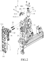
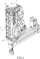
- the embodiment of a driving device is adapted for use in an electric nail gun 2.
- the electric nail gun 2 includes a supporting frame 21, a rotatable flywheel 22 pivotally mounted to the supporting frame 21, a motor 23 mounted to the supporting frame 21 and driving a high speed rotation of the flywheel 22, and an impact member 24 movable relative to the flywheel 22.
- the driving device includes a swing arm unit 3, a control unit 4 and a driving unit 5.
- the swing arm unit 3 includes a swing arm 31, a rod member 32 and two swing-arm biasing resilient members 33.
- the swing arm 31 is pivotally mounted to the supporting frame 21 and adapted to permit the impact member 24 to be movably mounted thereto, and has a pivot end 311 pivotally connected to the supporting frame 21, and a swinging end 312.
- the swing arm unit 3 is swingable between a standby position (see Figure 4 ) and a shooting position (see Figure 5 ) such that, when the swing arm unit 3 is at the standby position, the impact member 24 is spaced apart from the flywheel 22, and when the swing arm unit 3 is at the shooting position, the impact member 24 is in contact with the flywheel 22.
- the rod member 32 is fixedly received within the swinging end 312 of the swing arm 31, and is formed with an abutment surface 321.
- the swing-arm biasing resilient members 33 are disposed between the supporting frame 21 and the swinging end 312 of the swing arm 31 for biasing the swing arm unit 3 toward the standby position.
- the control unit 4 includes a control member 41 and a pivot pin 42.
- the control member 41 has a driven end portion 411, and an abutting end portion 412 opposite to the driven end portion 411 and slidably abutting against the abutment surface 321 of the swing arm unit 3.
- the control member 41 is pivotally mounted to the supporting frame 21 at a portion of the control member 41 which is disposed between the driven end portion 411 and the abutting end portion 412.
- the abutting end portion 412 of the control member 41 has an abutting surface 4121 abutting against the abutment surface 321 of the rod member 32.
- the control member 41 further has a connecting portion 414 connected between the abutting end portion 412 and the portion of the control member 41 which is disposed between the driven end portion 411 and the abutting end portion 412, and being not parallel to an extending line of the abutting surface 4121 of the abutting end portion 412.
- the pivot pin 42 connects rotatably the control member 41 to the supporting frame 21.
- An angle ( ⁇ ) is formed between the extending line of the abutting surface 4121 and a straight connecting line which extends through centers of the rod member 32 of the swing arm unit 3 and the pivot pin 42 of the control unit 4.
- the driving unit 5 is mounted to the supporting frame 21, and is for driving the driven end portion 411 of the control member 41 to rotate between a driving position (see Figure 5 ) and a non-driving position (see Figure 4 ) such that, when the driven end portion 411 of the control member 41 is at the driving position, the swing arm unit 3 is at the shooting position, and when the driven end portion 411 of the control member 41 is at the non-driving position, the swing arm unit 3 is at the standby position.
- the driving unit 5 includes a main body 51, a valve rod 52 movable relative to the main body 51 for rotating the driven end portion 411 of the control member 41 between the driving position and the non-driving position, and a control-member biasing resilient member 53.
- the control-member biasing resilient member 53 is disposed between the driven end portion 411 of the control member 41 and the supporting frame 21, and is for providing a resilient force to push the driven end portion 411 of the control member 41 to abut against the valve rod 52 so as to maintain the driven end portion 411 of the control member 41 at the non-driving position.
- the driving unit 5 is a solenoid valve.
- the angle ( ⁇ ) is ranged between 85 to 95 degrees.
- the angle ( ⁇ ) is ranged between 88 to 92 degrees, and the optimum angle ( ⁇ ) is 90 degrees.
- the driving device of the disclosure has the following advantages:
Landscapes
- Engineering & Computer Science (AREA)
- Mechanical Engineering (AREA)
- Chemical & Material Sciences (AREA)
- Combustion & Propulsion (AREA)
- Portable Nailing Machines And Staplers (AREA)
- Toys (AREA)
Claims (9)
- Dispositif d'entraînement destiné à être utilisé dans une cloueuse électrique (2), la cloueuse électrique (2) comportant un cadre de support (21), un volant rotatif (22) monté pivotant sur le cadre de support (21), et un élément d'impact (24), ledit dispositif d'entraînement comportant:une unité de bras oscillant (3) montée pivotante sur le cadre de support (21), comportant une surface de butée (321) adaptée pour permettre que l'élément d'impact (24) y soit monté de manière mobile, et oscillant entre une position d'attente et une position de tir de sorte que, lorsque ladite unité de bras oscillant (3) se trouve en position d'attente, l'élément d'impact (24) est éloigné du volant (22) et que, lorsque ladite unité de bras oscillant (3) se trouve en position de tir, l'élément d'impact (24) est en contact avec le volant (22);une unité de commande (4) comportant un élément de commande (41) qui présente une partie d'extrémité entraînée (411) et une partie d'extrémité venant en butée (412) opposée à ladite partie d'extrémité entraînée (411) et venant en butée en pivotement contre ladite surface de butée (321) de ladite unité de bras oscillant (3); etune unité d'entraînement (5) destinée à entraîner ladite partie d'extrémité entraînée (411) dudit élément de commande (41) en rotation entre une position d'entraînement et une position de non-entraînement de sorte que, lorsque ladite partie d'extrémité entraînée (411) dudit élément de commande (41) se trouve en position d'entraînement, ladite unité de bras oscillant se trouve en position de tir et que, lorsque ladite partie d'entraînement (411) dudit élément de commande (41) se trouve en position de non-entraînement, ladite unité de bras oscillant (3) se trouve en position d'attente, ladite unité d'entraînement (5) comportant un corps principal (51) et une tige de soupape (52) qui est mobile par rapport audit corps principal (51) pour faire tourneur ladite partie d'extrémité entraînée (411) dudit élément de commande (41) entre la position d'entraînement et la position de non-entraînement;caractérisé par le fait que ladite unité d'entraînement (5) comporte par ailleurs un élément élastique de sollicitation d'élément de commande (53) disposé entre ladite partie d'extrémité entraînée (411) dudit élément de commande (41) et le cadre de support (21) pour conférer une force élastique pour pousser ladite partie d'extrémité entraînée (411) dudit élément de commande (41) pour venir buter contre ladite tige de soupape (52) de manière à maintenir ladite partie d'extrémité entraînée (411) dudit élément de commande (41) en position de non-entraînement.
- Dispositif d'entraînement selon la revendication 1, caractérisé par ailleurs par le fait que ledit élément de commande (41) est monté de manière pivotante sur le cadre de support (21) à une partie dudit élément de commande (41) qui est disposée entre ladite partie d'extrémité entraînée (411) et ladite partie d'extrémité venant en butée (412).
- Dispositif d'entraînement selon l'une quelconque des revendications 1 et 2, caractérisé par ailleurs par le fait que ladite unité de commande (4) comporte par ailleurs une goupille de pivotement (42) connectant de manière rotative ledit élément de commande (41) au cadre de support (21).
- Dispositif d'entraînement selon l'une quelconque des revendications 1 à 3, caractérisé par ailleurs par le fait que:ladite unité de bras oscillant (3) comporte un bras oscillant (31) et un élément de tige (32);ledit bras oscillant (31) présente une extrémité de pivotement (311) connectée de manière pivotante au cadre de support (21), et une extrémité pivotante (312);ledit élément de tige (32) est reçu de manière fixe à l'intérieur de ladite extrémité oscillante (312) dudit bras oscillant (31), et est formé avec ladite surface de butée (321); etladite partie d'extrémité venant en butée (412) dudit élément de commande (41) présente une surface venant en butée (4121) qui vient en butée contre ladite surface de butée (321) dudit élément de tige (32) de sorte que, lorsque ladite partie d'extrémité entraînée (411) dudit élément de commande (41) se trouve en position d'entraînement, un angle (θ) soit formé entre une ligne d'extension de ladite surface venant en butée (4121) et une ligne de connexion droite qui s'étend à travers les centres dudit élément de tige (32) de ladite unité de bras oscillant (3) et de ladite goupille de pivotement (42) de ladite unité de commande (4).
- Dispositif d'entraînement selon la revendication 4, caractérisé par ailleurs par le fait que ladite unité de bras oscillant (3) comporte par ailleurs un élément élastique de sollicitation de bras oscillant (33) disposé entre le cadre de support (21) et ledit bras oscillant (31) destiné à solliciter ladite unité de bras oscillant (3) vers la position d'attente.
- Dispositif d'entraînement selon la revendication 4, caractérisé par ailleurs par le fait que l'angle (θ) est compris entre 85 et 95 degrés.
- Dispositif d'entraînement selon l'une quelconque des revendications 4 ou 6, caractérisé par ailleurs par le fait que l'angle (θ) est compris entre 88 et 92 degrés.
- Dispositif d'entraînement selon la revendication 4, caractérisé par ailleurs par le fait que ledit élément de commande (41) présente par ailleurs une partie de connexion (414) connectée entre ladite partie d'extrémité venant en butée (412) et la partie dudit élément de commande (41) qui est disposée entre ladite partie d'extrémité entraînée (411) et ladite partie d'extrémité venant en butée (412), et qui n'est pas parallèle à la ligne d'extension de ladite surface venant en butée (4121) de ladite partie d'extrémité venant en butée (412).
- Dispositif d'entraînement selon l'une quelconque des revendications 1 à 8, caractérisé par ailleurs par le fait que ladite unité d'entraînement (5) est une électrovanne.
Applications Claiming Priority (1)
| Application Number | Priority Date | Filing Date | Title |
|---|---|---|---|
| TW104133399A TWI532571B (zh) | 2015-10-12 | 2015-10-12 | Electric nail gun drive device |
Publications (3)
| Publication Number | Publication Date |
|---|---|
| EP3156182A2 EP3156182A2 (fr) | 2017-04-19 |
| EP3156182A3 EP3156182A3 (fr) | 2017-05-03 |
| EP3156182B1 true EP3156182B1 (fr) | 2018-04-18 |
Family
ID=56509225
Family Applications (2)
| Application Number | Title | Priority Date | Filing Date |
|---|---|---|---|
| EP16193304.9A Active EP3156182B1 (fr) | 2015-10-12 | 2016-10-11 | Dispositif de fixation |
| EP16193479.9A Withdrawn EP3156183A3 (fr) | 2015-10-12 | 2016-10-12 | Dispositif de transmission de carburant |
Family Applications After (1)
| Application Number | Title | Priority Date | Filing Date |
|---|---|---|---|
| EP16193479.9A Withdrawn EP3156183A3 (fr) | 2015-10-12 | 2016-10-12 | Dispositif de transmission de carburant |
Country Status (3)
| Country | Link |
|---|---|
| US (1) | US10195729B2 (fr) |
| EP (2) | EP3156182B1 (fr) |
| TW (1) | TWI532571B (fr) |
Cited By (2)
| Publication number | Priority date | Publication date | Assignee | Title |
|---|---|---|---|---|
| DE102024203165A1 (de) | 2024-04-08 | 2025-10-09 | Robert Bosch Gesellschaft mit beschränkter Haftung | Eintreibgerät mit einem Schwungradmechanismus |
| US12551998B2 (en) | 2021-05-24 | 2026-02-17 | Black & Decker Inc. | Flywheel driven fastening tool having at least two timeout periods for determining when to stop driving flywheel |
Families Citing this family (7)
| Publication number | Priority date | Publication date | Assignee | Title |
|---|---|---|---|---|
| TWI771560B (zh) | 2019-01-30 | 2022-07-21 | 鑽全實業股份有限公司 | 防止誤動作的飛輪式電動釘槍 |
| TWI815857B (zh) * | 2019-01-31 | 2023-09-21 | 鑽全實業股份有限公司 | 電動釘槍的飛輪裝置及電動釘槍 |
| TWI812797B (zh) * | 2019-10-23 | 2023-08-21 | 鑽全實業股份有限公司 | 飛輪式電動釘槍的衝擊裝置 |
| EP4081371A2 (fr) | 2019-12-24 | 2022-11-02 | Black & Decker Inc. | Outil de fixation entraîné par volant |
| TWI762323B (zh) | 2021-05-20 | 2022-04-21 | 鑽全實業股份有限公司 | 具有防誤擊作用的飛輪式電動釘槍及其擊釘裝置 |
| TW202400369A (zh) * | 2022-06-24 | 2024-01-01 | 鑽全實業股份有限公司 | 飛輪式電動釘槍 |
| TWI886869B (zh) * | 2024-03-26 | 2025-06-11 | 力肯實業股份有限公司 | 電動釘槍的旋轉驅動組 |
Family Cites Families (27)
| Publication number | Priority date | Publication date | Assignee | Title |
|---|---|---|---|---|
| US4403722A (en) * | 1981-01-22 | 1983-09-13 | Signode Corporation | Combustion gas powered fastener driving tool |
| US5098004A (en) | 1989-12-19 | 1992-03-24 | Duo-Fast Corporation | Fastener driving tool |
| US6669072B2 (en) * | 2000-12-22 | 2003-12-30 | Senco Products, Inc. | Flywheel operated nailer |
| US7331403B2 (en) | 2004-04-02 | 2008-02-19 | Black & Decker Inc. | Lock-out for activation arm mechanism in a power tool |
| US8302833B2 (en) * | 2004-04-02 | 2012-11-06 | Black & Decker Inc. | Power take off for cordless nailer |
| US7478740B2 (en) | 2006-06-30 | 2009-01-20 | Illinois Tool Works Inc. | Enhanced fuel passageway and adapter for combustion tool fuel cell |
| US6971567B1 (en) * | 2004-10-29 | 2005-12-06 | Black & Decker Inc. | Electronic control of a cordless fastening tool |
| JP4688060B2 (ja) * | 2005-10-28 | 2011-05-25 | 日立工機株式会社 | 打込機 |
| TW200906574A (en) * | 2007-08-03 | 2009-02-16 | De Poan Pneumatic Corp | Transmission device of nailing gun device |
| JP5001751B2 (ja) * | 2007-08-27 | 2012-08-15 | 株式会社マキタ | 打込み工具 |
| US7575141B1 (en) * | 2008-02-04 | 2009-08-18 | De Poan Pneumatic Corp. | Actuator for electrical nail gun |
| US8534527B2 (en) * | 2008-04-03 | 2013-09-17 | Black & Decker Inc. | Cordless framing nailer |
| US9216502B2 (en) * | 2008-04-03 | 2015-12-22 | Black & Decker Inc. | Multi-stranded return spring for fastening tool |
| DE602009001046D1 (de) * | 2008-05-30 | 2011-05-26 | Black & Decker Inc | Werkzeug zum Antreiben von Befestigungselementen |
| US7905377B2 (en) * | 2008-08-14 | 2011-03-15 | Robert Bosch Gmbh | Flywheel driven nailer with safety mechanism |
| TWI385058B (zh) * | 2010-04-26 | 2013-02-11 | Basso Ind Corp | Electric nail gun drive device |
| TWI385059B (zh) * | 2010-04-27 | 2013-02-11 | Basso Ind Corp | Floating impulse unit of electric nail gun |
| TWI381915B (zh) | 2010-09-16 | 2013-01-11 | Basso Ind Corp | An electric nail gun with an error prevention function |
| WO2015134076A1 (fr) * | 2014-03-03 | 2015-09-11 | Illinois Tool Works Inc. | Interface pour système de distribution de combustible pour cloueuse à combustion |
| JP5741233B2 (ja) * | 2011-06-10 | 2015-07-01 | マックス株式会社 | 燃料容器保持構造 |
| US8991675B2 (en) * | 2011-12-19 | 2015-03-31 | De Poan Pneumatic Corp. | Dynamic clutch apparatus for electrical nail gun |
| TW201338936A (zh) | 2012-03-28 | 2013-10-01 | Basso Ind Corp | 電動釘槍的衝擊裝置 |
| US9399281B2 (en) * | 2012-09-20 | 2016-07-26 | Black & Decker Inc. | Stall release lever for fastening tool |
| US9744657B2 (en) * | 2012-10-04 | 2017-08-29 | Black & Decker Inc. | Activation system having multi-angled arm and stall release mechanism |
| TWM482482U (zh) * | 2014-03-10 | 2014-07-21 | Basso Ind Corp | 電動釘槍回收裝置 |
| TWM486527U (zh) * | 2014-05-08 | 2014-09-21 | Basso Ind Corp | 瓦斯釘槍及其瓦斯瓶驅動器 |
| DE202015003261U1 (de) * | 2015-05-06 | 2015-06-01 | Olaf Kersten | Gasbetriebenes Setzgerät |
-
2015
- 2015-10-12 TW TW104133399A patent/TWI532571B/zh active
-
2016
- 2016-10-10 US US15/289,270 patent/US10195729B2/en active Active
- 2016-10-11 EP EP16193304.9A patent/EP3156182B1/fr active Active
- 2016-10-12 EP EP16193479.9A patent/EP3156183A3/fr not_active Withdrawn
Non-Patent Citations (1)
| Title |
|---|
| None * |
Cited By (2)
| Publication number | Priority date | Publication date | Assignee | Title |
|---|---|---|---|---|
| US12551998B2 (en) | 2021-05-24 | 2026-02-17 | Black & Decker Inc. | Flywheel driven fastening tool having at least two timeout periods for determining when to stop driving flywheel |
| DE102024203165A1 (de) | 2024-04-08 | 2025-10-09 | Robert Bosch Gesellschaft mit beschränkter Haftung | Eintreibgerät mit einem Schwungradmechanismus |
Also Published As
| Publication number | Publication date |
|---|---|
| EP3156183A3 (fr) | 2017-05-17 |
| US20170100828A1 (en) | 2017-04-13 |
| US10195729B2 (en) | 2019-02-05 |
| EP3156182A2 (fr) | 2017-04-19 |
| EP3156183A2 (fr) | 2017-04-19 |
| EP3156182A3 (fr) | 2017-05-03 |
| TW201713468A (zh) | 2017-04-16 |
| TWI532571B (zh) | 2016-05-11 |
Similar Documents
| Publication | Publication Date | Title |
|---|---|---|
| EP3156182B1 (fr) | Dispositif de fixation | |
| EP2644323B1 (fr) | Cloueuse électrique | |
| JP2018112050A5 (fr) | ||
| US11518013B2 (en) | Electric nail gun | |
| US11305409B2 (en) | Retrieving device and impact mechanism for an electric nail gun having the same | |
| US20150306753A1 (en) | Adjusting device for an electric nail gun | |
| US20150251300A1 (en) | Electric nail gun | |
| EP2433752A2 (fr) | Unité d'entraînement pour cloueuse électrique | |
| US11819991B2 (en) | Retaining device for use with a nail gun | |
| EP3378600B1 (fr) | Dispositif de retour | |
| US9446297B2 (en) | Device for throwing balls | |
| EP4434687B1 (fr) | Appareil de travail manuel doté d'un tube de guidage | |
| US9803948B2 (en) | Trigger emulation mechanism of electric gun | |
| JP5403746B2 (ja) | バドミントン用のシャトル発射装置 | |
| US11738431B2 (en) | Retaining device for use with a nail gun | |
| JP2005034476A5 (fr) | ||
| EP4029653B1 (fr) | Dispositif de retenue à utiliser avec une cloueuse | |
| EP4349533A1 (fr) | Pistolet à clouer électrique | |
| EP4549093A1 (fr) | Pistolet à clouer électrique | |
| JPH0346786Y2 (fr) | ||
| EP3040674B1 (fr) | Mécanisme d'émulation de déclenchement de pistolet électrique | |
| JPH0346784Y2 (fr) | ||
| JP2019165939A5 (fr) | ||
| JPS6150577A (ja) | 打撃練習機 | |
| JP2003117223A (ja) | 景品把持具 |
Legal Events
| Date | Code | Title | Description |
|---|---|---|---|
| PUAI | Public reference made under article 153(3) epc to a published international application that has entered the european phase |
Free format text: ORIGINAL CODE: 0009012 |
|
| PUAL | Search report despatched |
Free format text: ORIGINAL CODE: 0009013 |
|
| 17P | Request for examination filed |
Effective date: 20161011 |
|
| AK | Designated contracting states |
Kind code of ref document: A2 Designated state(s): AL AT BE BG CH CY CZ DE DK EE ES FI FR GB GR HR HU IE IS IT LI LT LU LV MC MK MT NL NO PL PT RO RS SE SI SK SM TR |
|
| AX | Request for extension of the european patent |
Extension state: BA ME |
|
| AK | Designated contracting states |
Kind code of ref document: A3 Designated state(s): AL AT BE BG CH CY CZ DE DK EE ES FI FR GB GR HR HU IE IS IT LI LT LU LV MC MK MT NL NO PL PT RO RS SE SI SK SM TR |
|
| AX | Request for extension of the european patent |
Extension state: BA ME |
|
| RIC1 | Information provided on ipc code assigned before grant |
Ipc: B25C 1/06 20060101AFI20170330BHEP |
|
| GRAP | Despatch of communication of intention to grant a patent |
Free format text: ORIGINAL CODE: EPIDOSNIGR1 |
|
| INTG | Intention to grant announced |
Effective date: 20171103 |
|
| GRAS | Grant fee paid |
Free format text: ORIGINAL CODE: EPIDOSNIGR3 |
|
| GRAA | (expected) grant |
Free format text: ORIGINAL CODE: 0009210 |
|
| AK | Designated contracting states |
Kind code of ref document: B1 Designated state(s): AL AT BE BG CH CY CZ DE DK EE ES FI FR GB GR HR HU IE IS IT LI LT LU LV MC MK MT NL NO PL PT RO RS SE SI SK SM TR |
|
| REG | Reference to a national code |
Ref country code: GB Ref legal event code: FG4D |
|
| REG | Reference to a national code |
Ref country code: CH Ref legal event code: EP |
|
| REG | Reference to a national code |
Ref country code: AT Ref legal event code: REF Ref document number: 989922 Country of ref document: AT Kind code of ref document: T Effective date: 20180515 |
|
| REG | Reference to a national code |
Ref country code: IE Ref legal event code: FG4D |
|
| REG | Reference to a national code |
Ref country code: DE Ref legal event code: R096 Ref document number: 602016002593 Country of ref document: DE |
|
| REG | Reference to a national code |
Ref country code: NL Ref legal event code: MP Effective date: 20180418 |
|
| REG | Reference to a national code |
Ref country code: LT Ref legal event code: MG4D |
|
| PG25 | Lapsed in a contracting state [announced via postgrant information from national office to epo] |
Ref country code: NL Free format text: LAPSE BECAUSE OF FAILURE TO SUBMIT A TRANSLATION OF THE DESCRIPTION OR TO PAY THE FEE WITHIN THE PRESCRIBED TIME-LIMIT Effective date: 20180418 |
|
| REG | Reference to a national code |
Ref country code: FR Ref legal event code: PLFP Year of fee payment: 3 |
|
| PG25 | Lapsed in a contracting state [announced via postgrant information from national office to epo] |
Ref country code: PL Free format text: LAPSE BECAUSE OF FAILURE TO SUBMIT A TRANSLATION OF THE DESCRIPTION OR TO PAY THE FEE WITHIN THE PRESCRIBED TIME-LIMIT Effective date: 20180418 Ref country code: FI Free format text: LAPSE BECAUSE OF FAILURE TO SUBMIT A TRANSLATION OF THE DESCRIPTION OR TO PAY THE FEE WITHIN THE PRESCRIBED TIME-LIMIT Effective date: 20180418 Ref country code: LT Free format text: LAPSE BECAUSE OF FAILURE TO SUBMIT A TRANSLATION OF THE DESCRIPTION OR TO PAY THE FEE WITHIN THE PRESCRIBED TIME-LIMIT Effective date: 20180418 Ref country code: SE Free format text: LAPSE BECAUSE OF FAILURE TO SUBMIT A TRANSLATION OF THE DESCRIPTION OR TO PAY THE FEE WITHIN THE PRESCRIBED TIME-LIMIT Effective date: 20180418 Ref country code: NO Free format text: LAPSE BECAUSE OF FAILURE TO SUBMIT A TRANSLATION OF THE DESCRIPTION OR TO PAY THE FEE WITHIN THE PRESCRIBED TIME-LIMIT Effective date: 20180718 Ref country code: AL Free format text: LAPSE BECAUSE OF FAILURE TO SUBMIT A TRANSLATION OF THE DESCRIPTION OR TO PAY THE FEE WITHIN THE PRESCRIBED TIME-LIMIT Effective date: 20180418 Ref country code: ES Free format text: LAPSE BECAUSE OF FAILURE TO SUBMIT A TRANSLATION OF THE DESCRIPTION OR TO PAY THE FEE WITHIN THE PRESCRIBED TIME-LIMIT Effective date: 20180418 Ref country code: BG Free format text: LAPSE BECAUSE OF FAILURE TO SUBMIT A TRANSLATION OF THE DESCRIPTION OR TO PAY THE FEE WITHIN THE PRESCRIBED TIME-LIMIT Effective date: 20180718 |
|
| PG25 | Lapsed in a contracting state [announced via postgrant information from national office to epo] |
Ref country code: RS Free format text: LAPSE BECAUSE OF FAILURE TO SUBMIT A TRANSLATION OF THE DESCRIPTION OR TO PAY THE FEE WITHIN THE PRESCRIBED TIME-LIMIT Effective date: 20180418 Ref country code: LV Free format text: LAPSE BECAUSE OF FAILURE TO SUBMIT A TRANSLATION OF THE DESCRIPTION OR TO PAY THE FEE WITHIN THE PRESCRIBED TIME-LIMIT Effective date: 20180418 Ref country code: HR Free format text: LAPSE BECAUSE OF FAILURE TO SUBMIT A TRANSLATION OF THE DESCRIPTION OR TO PAY THE FEE WITHIN THE PRESCRIBED TIME-LIMIT Effective date: 20180418 Ref country code: GR Free format text: LAPSE BECAUSE OF FAILURE TO SUBMIT A TRANSLATION OF THE DESCRIPTION OR TO PAY THE FEE WITHIN THE PRESCRIBED TIME-LIMIT Effective date: 20180719 |
|
| REG | Reference to a national code |
Ref country code: AT Ref legal event code: MK05 Ref document number: 989922 Country of ref document: AT Kind code of ref document: T Effective date: 20180418 |
|
| REG | Reference to a national code |
Ref country code: DE Ref legal event code: R097 Ref document number: 602016002593 Country of ref document: DE |
|
| PG25 | Lapsed in a contracting state [announced via postgrant information from national office to epo] |
Ref country code: AT Free format text: LAPSE BECAUSE OF FAILURE TO SUBMIT A TRANSLATION OF THE DESCRIPTION OR TO PAY THE FEE WITHIN THE PRESCRIBED TIME-LIMIT Effective date: 20180418 Ref country code: EE Free format text: LAPSE BECAUSE OF FAILURE TO SUBMIT A TRANSLATION OF THE DESCRIPTION OR TO PAY THE FEE WITHIN THE PRESCRIBED TIME-LIMIT Effective date: 20180418 Ref country code: DK Free format text: LAPSE BECAUSE OF FAILURE TO SUBMIT A TRANSLATION OF THE DESCRIPTION OR TO PAY THE FEE WITHIN THE PRESCRIBED TIME-LIMIT Effective date: 20180418 Ref country code: RO Free format text: LAPSE BECAUSE OF FAILURE TO SUBMIT A TRANSLATION OF THE DESCRIPTION OR TO PAY THE FEE WITHIN THE PRESCRIBED TIME-LIMIT Effective date: 20180418 Ref country code: CZ Free format text: LAPSE BECAUSE OF FAILURE TO SUBMIT A TRANSLATION OF THE DESCRIPTION OR TO PAY THE FEE WITHIN THE PRESCRIBED TIME-LIMIT Effective date: 20180418 Ref country code: SK Free format text: LAPSE BECAUSE OF FAILURE TO SUBMIT A TRANSLATION OF THE DESCRIPTION OR TO PAY THE FEE WITHIN THE PRESCRIBED TIME-LIMIT Effective date: 20180418 |
|
| PLBE | No opposition filed within time limit |
Free format text: ORIGINAL CODE: 0009261 |
|
| STAA | Information on the status of an ep patent application or granted ep patent |
Free format text: STATUS: NO OPPOSITION FILED WITHIN TIME LIMIT |
|
| PG25 | Lapsed in a contracting state [announced via postgrant information from national office to epo] |
Ref country code: SM Free format text: LAPSE BECAUSE OF FAILURE TO SUBMIT A TRANSLATION OF THE DESCRIPTION OR TO PAY THE FEE WITHIN THE PRESCRIBED TIME-LIMIT Effective date: 20180418 Ref country code: IT Free format text: LAPSE BECAUSE OF FAILURE TO SUBMIT A TRANSLATION OF THE DESCRIPTION OR TO PAY THE FEE WITHIN THE PRESCRIBED TIME-LIMIT Effective date: 20180418 |
|
| 26N | No opposition filed |
Effective date: 20190121 |
|
| PG25 | Lapsed in a contracting state [announced via postgrant information from national office to epo] |
Ref country code: SI Free format text: LAPSE BECAUSE OF FAILURE TO SUBMIT A TRANSLATION OF THE DESCRIPTION OR TO PAY THE FEE WITHIN THE PRESCRIBED TIME-LIMIT Effective date: 20180418 |
|
| REG | Reference to a national code |
Ref country code: BE Ref legal event code: MM Effective date: 20181031 |
|
| PG25 | Lapsed in a contracting state [announced via postgrant information from national office to epo] |
Ref country code: LU Free format text: LAPSE BECAUSE OF NON-PAYMENT OF DUE FEES Effective date: 20181011 Ref country code: MC Free format text: LAPSE BECAUSE OF FAILURE TO SUBMIT A TRANSLATION OF THE DESCRIPTION OR TO PAY THE FEE WITHIN THE PRESCRIBED TIME-LIMIT Effective date: 20180418 |
|
| REG | Reference to a national code |
Ref country code: IE Ref legal event code: MM4A |
|
| PG25 | Lapsed in a contracting state [announced via postgrant information from national office to epo] |
Ref country code: BE Free format text: LAPSE BECAUSE OF NON-PAYMENT OF DUE FEES Effective date: 20181031 |
|
| PG25 | Lapsed in a contracting state [announced via postgrant information from national office to epo] |
Ref country code: IE Free format text: LAPSE BECAUSE OF NON-PAYMENT OF DUE FEES Effective date: 20181011 |
|
| PG25 | Lapsed in a contracting state [announced via postgrant information from national office to epo] |
Ref country code: MT Free format text: LAPSE BECAUSE OF NON-PAYMENT OF DUE FEES Effective date: 20181011 |
|
| PG25 | Lapsed in a contracting state [announced via postgrant information from national office to epo] |
Ref country code: TR Free format text: LAPSE BECAUSE OF FAILURE TO SUBMIT A TRANSLATION OF THE DESCRIPTION OR TO PAY THE FEE WITHIN THE PRESCRIBED TIME-LIMIT Effective date: 20180418 |
|
| PG25 | Lapsed in a contracting state [announced via postgrant information from national office to epo] |
Ref country code: PT Free format text: LAPSE BECAUSE OF FAILURE TO SUBMIT A TRANSLATION OF THE DESCRIPTION OR TO PAY THE FEE WITHIN THE PRESCRIBED TIME-LIMIT Effective date: 20180418 |
|
| REG | Reference to a national code |
Ref country code: CH Ref legal event code: PL |
|
| PG25 | Lapsed in a contracting state [announced via postgrant information from national office to epo] |
Ref country code: MK Free format text: LAPSE BECAUSE OF NON-PAYMENT OF DUE FEES Effective date: 20180418 Ref country code: CY Free format text: LAPSE BECAUSE OF FAILURE TO SUBMIT A TRANSLATION OF THE DESCRIPTION OR TO PAY THE FEE WITHIN THE PRESCRIBED TIME-LIMIT Effective date: 20180418 Ref country code: HU Free format text: LAPSE BECAUSE OF FAILURE TO SUBMIT A TRANSLATION OF THE DESCRIPTION OR TO PAY THE FEE WITHIN THE PRESCRIBED TIME-LIMIT; INVALID AB INITIO Effective date: 20161011 |
|
| PG25 | Lapsed in a contracting state [announced via postgrant information from national office to epo] |
Ref country code: CH Free format text: LAPSE BECAUSE OF NON-PAYMENT OF DUE FEES Effective date: 20191031 Ref country code: LI Free format text: LAPSE BECAUSE OF NON-PAYMENT OF DUE FEES Effective date: 20191031 Ref country code: IS Free format text: LAPSE BECAUSE OF FAILURE TO SUBMIT A TRANSLATION OF THE DESCRIPTION OR TO PAY THE FEE WITHIN THE PRESCRIBED TIME-LIMIT Effective date: 20180818 |
|
| PGFP | Annual fee paid to national office [announced via postgrant information from national office to epo] |
Ref country code: GB Payment date: 20250904 Year of fee payment: 10 |
|
| PGFP | Annual fee paid to national office [announced via postgrant information from national office to epo] |
Ref country code: FR Payment date: 20250908 Year of fee payment: 10 |
|
| PGFP | Annual fee paid to national office [announced via postgrant information from national office to epo] |
Ref country code: DE Payment date: 20250902 Year of fee payment: 10 |