EP3156206B1 - Rouleau de transfert pour l'estampage - Google Patents
Rouleau de transfert pour l'estampage Download PDFInfo
- Publication number
- EP3156206B1 EP3156206B1 EP15805754.7A EP15805754A EP3156206B1 EP 3156206 B1 EP3156206 B1 EP 3156206B1 EP 15805754 A EP15805754 A EP 15805754A EP 3156206 B1 EP3156206 B1 EP 3156206B1
- Authority
- EP
- European Patent Office
- Prior art keywords
- divided
- roll
- divided body
- film substrate
- resin film
- Prior art date
- Legal status (The legal status is an assumption and is not a legal conclusion. Google has not performed a legal analysis and makes no representation as to the accuracy of the status listed.)
- Not-in-force
Links
- 239000011347 resin Substances 0.000 claims description 90
- 229920005989 resin Polymers 0.000 claims description 90
- 239000000758 substrate Substances 0.000 claims description 43
- 230000002093 peripheral effect Effects 0.000 claims description 7
- 238000000034 method Methods 0.000 description 22
- 239000004820 Pressure-sensitive adhesive Substances 0.000 description 11
- 239000000463 material Substances 0.000 description 8
- 239000000853 adhesive Substances 0.000 description 1
- 230000001070 adhesive effect Effects 0.000 description 1
- 239000003963 antioxidant agent Substances 0.000 description 1
- 230000003078 antioxidant effect Effects 0.000 description 1
- 239000000919 ceramic Substances 0.000 description 1
- 239000003795 chemical substances by application Substances 0.000 description 1
- 229920001577 copolymer Polymers 0.000 description 1
- 230000000694 effects Effects 0.000 description 1
- 229920001971 elastomer Polymers 0.000 description 1
- 238000005323 electroforming Methods 0.000 description 1
- 239000000945 filler Substances 0.000 description 1
- 239000011521 glass Substances 0.000 description 1
- 239000007788 liquid Substances 0.000 description 1
- 239000000696 magnetic material Substances 0.000 description 1
- 238000004519 manufacturing process Methods 0.000 description 1
- 239000002184 metal Substances 0.000 description 1
- 229910052751 metal Inorganic materials 0.000 description 1
- 150000002739 metals Chemical class 0.000 description 1
- 230000003287 optical effect Effects 0.000 description 1
- 239000003504 photosensitizing agent Substances 0.000 description 1
- 239000004033 plastic Substances 0.000 description 1
- 229920003023 plastic Polymers 0.000 description 1
- 229920001296 polysiloxane Polymers 0.000 description 1
- 239000010453 quartz Substances 0.000 description 1
- 239000005060 rubber Substances 0.000 description 1
- 239000004065 semiconductor Substances 0.000 description 1
- VYPSYNLAJGMNEJ-UHFFFAOYSA-N silicon dioxide Inorganic materials O=[Si]=O VYPSYNLAJGMNEJ-UHFFFAOYSA-N 0.000 description 1
- 229920002545 silicone oil Polymers 0.000 description 1
- 229920002379 silicone rubber Polymers 0.000 description 1
- 239000004945 silicone rubber Substances 0.000 description 1
- 238000004804 winding Methods 0.000 description 1
Images


Classifications
-
- B—PERFORMING OPERATIONS; TRANSPORTING
- B01—PHYSICAL OR CHEMICAL PROCESSES OR APPARATUS IN GENERAL
- B01D—SEPARATION
- B01D59/00—Separation of different isotopes of the same chemical element
- B01D59/02—Separation by phase transition
- B01D59/04—Separation by phase transition by distillation
-
- B—PERFORMING OPERATIONS; TRANSPORTING
- B29—WORKING OF PLASTICS; WORKING OF SUBSTANCES IN A PLASTIC STATE IN GENERAL
- B29C—SHAPING OR JOINING OF PLASTICS; SHAPING OF MATERIAL IN A PLASTIC STATE, NOT OTHERWISE PROVIDED FOR; AFTER-TREATMENT OF THE SHAPED PRODUCTS, e.g. REPAIRING
- B29C59/00—Surface shaping of articles, e.g. embossing; Apparatus therefor
- B29C59/02—Surface shaping of articles, e.g. embossing; Apparatus therefor by mechanical means, e.g. pressing
- B29C59/04—Surface shaping of articles, e.g. embossing; Apparatus therefor by mechanical means, e.g. pressing using rollers or endless belts
-
- B—PERFORMING OPERATIONS; TRANSPORTING
- B32—LAYERED PRODUCTS
- B32B—LAYERED PRODUCTS, i.e. PRODUCTS BUILT-UP OF STRATA OF FLAT OR NON-FLAT, e.g. CELLULAR OR HONEYCOMB, FORM
- B32B37/00—Methods or apparatus for laminating, e.g. by curing or by ultrasonic bonding
- B32B37/0046—Methods or apparatus for laminating, e.g. by curing or by ultrasonic bonding characterised by constructional aspects of the apparatus
- B32B37/0053—Constructional details of laminating machines comprising rollers; Constructional features of the rollers
-
- B—PERFORMING OPERATIONS; TRANSPORTING
- B29—WORKING OF PLASTICS; WORKING OF SUBSTANCES IN A PLASTIC STATE IN GENERAL
- B29C—SHAPING OR JOINING OF PLASTICS; SHAPING OF MATERIAL IN A PLASTIC STATE, NOT OTHERWISE PROVIDED FOR; AFTER-TREATMENT OF THE SHAPED PRODUCTS, e.g. REPAIRING
- B29C33/00—Moulds or cores; Details thereof or accessories therefor
- B29C33/38—Moulds or cores; Details thereof or accessories therefor characterised by the material or the manufacturing process
-
- B—PERFORMING OPERATIONS; TRANSPORTING
- B29—WORKING OF PLASTICS; WORKING OF SUBSTANCES IN A PLASTIC STATE IN GENERAL
- B29C—SHAPING OR JOINING OF PLASTICS; SHAPING OF MATERIAL IN A PLASTIC STATE, NOT OTHERWISE PROVIDED FOR; AFTER-TREATMENT OF THE SHAPED PRODUCTS, e.g. REPAIRING
- B29C59/00—Surface shaping of articles, e.g. embossing; Apparatus therefor
- B29C59/002—Component parts, details or accessories; Auxiliary operations
-
- G—PHYSICS
- G03—PHOTOGRAPHY; CINEMATOGRAPHY; ANALOGOUS TECHNIQUES USING WAVES OTHER THAN OPTICAL WAVES; ELECTROGRAPHY; HOLOGRAPHY
- G03F—PHOTOMECHANICAL PRODUCTION OF TEXTURED OR PATTERNED SURFACES, e.g. FOR PRINTING, FOR PROCESSING OF SEMICONDUCTOR DEVICES; MATERIALS THEREFOR; ORIGINALS THEREFOR; APPARATUS SPECIALLY ADAPTED THEREFOR
- G03F7/00—Photomechanical, e.g. photolithographic, production of textured or patterned surfaces, e.g. printing surfaces; Materials therefor, e.g. comprising photoresists; Apparatus specially adapted therefor
- G03F7/0002—Lithographic processes using patterning methods other than those involving the exposure to radiation, e.g. by stamping
-
- B—PERFORMING OPERATIONS; TRANSPORTING
- B29—WORKING OF PLASTICS; WORKING OF SUBSTANCES IN A PLASTIC STATE IN GENERAL
- B29C—SHAPING OR JOINING OF PLASTICS; SHAPING OF MATERIAL IN A PLASTIC STATE, NOT OTHERWISE PROVIDED FOR; AFTER-TREATMENT OF THE SHAPED PRODUCTS, e.g. REPAIRING
- B29C43/00—Compression moulding, i.e. applying external pressure to flow the moulding material; Apparatus therefor
- B29C43/02—Compression moulding, i.e. applying external pressure to flow the moulding material; Apparatus therefor of articles of definite length, i.e. discrete articles
- B29C43/021—Compression moulding, i.e. applying external pressure to flow the moulding material; Apparatus therefor of articles of definite length, i.e. discrete articles characterised by the shape of the surface
- B29C2043/023—Compression moulding, i.e. applying external pressure to flow the moulding material; Apparatus therefor of articles of definite length, i.e. discrete articles characterised by the shape of the surface having a plurality of grooves
- B29C2043/025—Compression moulding, i.e. applying external pressure to flow the moulding material; Apparatus therefor of articles of definite length, i.e. discrete articles characterised by the shape of the surface having a plurality of grooves forming a microstructure, i.e. fine patterning
-
- B—PERFORMING OPERATIONS; TRANSPORTING
- B29—WORKING OF PLASTICS; WORKING OF SUBSTANCES IN A PLASTIC STATE IN GENERAL
- B29C—SHAPING OR JOINING OF PLASTICS; SHAPING OF MATERIAL IN A PLASTIC STATE, NOT OTHERWISE PROVIDED FOR; AFTER-TREATMENT OF THE SHAPED PRODUCTS, e.g. REPAIRING
- B29C59/00—Surface shaping of articles, e.g. embossing; Apparatus therefor
- B29C59/02—Surface shaping of articles, e.g. embossing; Apparatus therefor by mechanical means, e.g. pressing
- B29C59/022—Surface shaping of articles, e.g. embossing; Apparatus therefor by mechanical means, e.g. pressing characterised by the disposition or the configuration, e.g. dimensions, of the embossments or the shaping tools therefor
- B29C2059/023—Microembossing
-
- B—PERFORMING OPERATIONS; TRANSPORTING
- B29—WORKING OF PLASTICS; WORKING OF SUBSTANCES IN A PLASTIC STATE IN GENERAL
- B29L—INDEXING SCHEME ASSOCIATED WITH SUBCLASS B29C, RELATING TO PARTICULAR ARTICLES
- B29L2007/00—Flat articles, e.g. films or sheets
- B29L2007/008—Wide strips, e.g. films, webs
-
- B—PERFORMING OPERATIONS; TRANSPORTING
- B32—LAYERED PRODUCTS
- B32B—LAYERED PRODUCTS, i.e. PRODUCTS BUILT-UP OF STRATA OF FLAT OR NON-FLAT, e.g. CELLULAR OR HONEYCOMB, FORM
- B32B38/00—Ancillary operations in connection with laminating processes
- B32B38/06—Embossing
Definitions
- the present invention relates to an imprinting transfer roll for use in an imprinting device.
- Nanoimprinting technique is a technique to press a mold having a recessed-protruded pattern formed thereon against a liquid resin or the like on a substrate to transfer the pattern of the mold to the resin.
- recessed-protruded patterns patterns ranging from nanoscale patterns of 10 nm level to patterns of about 100 ⁇ m are present, and they are used in various fields, such as fields of semiconductor materials, optical materials, storage media, micromachines, biotechnology and environment.
- Devices for use in the nanoimprinting technique include devices of roll transfer system, such as a device of so-called roll-to-plate system to transfer the shape of a mold on a roll to a resin on a flat substrate and a device of so-called roll-to-roll system to transfer the shape of a mold on a roll to a resin on a roll.
- devices of roll transfer system such as a device of so-called roll-to-plate system to transfer the shape of a mold on a roll to a resin on a flat substrate and a device of so-called roll-to-roll system to transfer the shape of a mold on a roll to a resin on a roll.
- a method comprising fixing a mold made of a film, which has been affixed to a film, to a roll by means of a pressure-sensitive adhesive tape has been carried out.
- a pressure-sensitive adhesive tape is used in such a manner, there area problem of occurrence of a difference in level attributable to the pressure-sensitive adhesive tape and a problem that the alignment of the mold with a transfer object resin varies for each production lot because the adhesion position on the roll in the width direction of the roll and the adhesion angle to the roll cannot be accurately determined.
- the present invention addresses the problem of fixing a resin mold to the accurate position on a roll used in an imprinting device of roll transfer system in a simple manner and thereby facilitating control of alignment of the resin mold with a transfer object resin.
- the present invention relates to, for example, the following [1] to [5] .
- a resin mold can be set at the accurate position on a roll and fixed thereto by a simple method comprising sandwiching one end of a resin film substrate having a resin mold affixed thereto between two divided bodies obtained by dividing a roll body into two and preferably inserting a pin provided on one divided body into a mounting hole provided in the above one end part of the resin film substrate.
- the imprinting transfer roll of the present invention is an imprinting transfer roll comprising a roll body around a peripheral surface of which a resin film substrate is to be wound, to said resin film substrate a resin mold having a fine recessed-protruded pattern formed on its surface having been affixed, wherein: the roll body is divided into two and thereby constituted of one divided body and the other divided body, and between divided faces of these first divided body and second divided body to be joined together, one end of the resin film substrate is to be sandwiched to integrate the first divided body and the second divided body, and then the resin film substrate is to be wound around in the circumferential direction of the roll body.
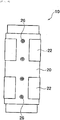
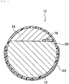
- Fig. 1 to Fig. 4 each show an imprinting transfer roll according to a preferred embodiment of the present invention.
- a roll body 10a is divided into two and thereby constituted of a first divided body 12 and a second divided body 14.
- the sizes of the first divided body 12 and the second divided body 14 are not restricted at all, and the roll body may be divided in the middle to form the first divided body 12 and the second divided body 14 having the same shapes as each other, or the size of one divided body may be made larger than that of the other divided body.
- the roll body 10a may be divided into two by a plane parallel to the axial direction of the roll body or may be divided into a sectorial shape.
- the material of the roll body 10a is not specifically restricted, and preferred examples of the materials include metals, rubbers, plastics, ceramics, quartz and glasses.
- the roll body 10a is divided into two by a plane parallel to the axial direction of the roll body, it is preferable that plural pins 16 (four pins in this embodiment) protrude from a divided face 12a of the first divided body 12.
- pin holes 18 are formed at the positions corresponding to the pins 16, respectively, as shown in Fig. 2 .
- the roll body 10a thus divided into two is set in such a manner that when the divided faces of the first divided body 12 and the second divided body 14 are fitted to each other, these divided bodies can undergo pinned connection by means of the pins 16 and the pin holes 18.
- the angle ⁇ between the divided face (face having pins protruding therefrom) formed by the divided portion 12 and a tangent line to the roll body 10a on the outer periphery of the roll body 10a at the divided face is preferably in the range of 91° to 170°, more preferably in the range of 105° to 150°. That is to say, with regard to the abutting faces of the first divided body 12 and the second divided body 14, one of them may protrude at an angle in the range of 91° to 170° and the other may be formed of a concave curved face.
- a stress occurring is small even if the resin mold 22 is wound around, and therefore, the recessed-protruded pattern tends to be maintained.
- the above materials may contain components, such as antioxidant, photosensitizer, filler and leveling agent, in such a range as exerts no influence on the properties of the resin.
- the thickness of the resin mold 22 is usually 50 nm to 300 ⁇ m, preferably 500 nm to 10 ⁇ m.
- the resin mold not only has strength to withstand imprinting but also has good smoothness and ease of handling.
- the thickness of the resin mold refers to a distance between the bottom surface of the resin layer and the highest plane of the recessions and protrusions on the surface.
- the recessed-protruded pattern on the surface of the resin mold 22 is a pattern in which a recession and a protrusion are repeated in a certain cycle, and preferable is a recessed-protruded pattern having a cycle of 10 nm to 50 cm, a depth of 10 nm to 100 ⁇ m and a transfer surface of 1.0 to 1.0 ⁇ 10 6 mm 2 .
- Examples of specific shapes of the recessions and protrusions include line, column, monolith, cone, pyramid and microlens.
- the length of the resin mold 22 in the outer circumferential direction of the roll is not specifically restricted, and the length may be shorter or longer than the length of the outer periphery of the roll, but from the viewpoint that the resin mold is stably seized to the roll, it is preferable that the length of the resin mold is exactly the same as the length of the outer periphery of the roll.
- the shortage portion may be filled with a peelable resin in accordance with the description of WO2013/031460 .
- mounting holes 24 are preferably formed at certain intervals so that the pins 16 protruding from the first divided body 12 can be mounted into them, as shown in Fig. 1 to Fig. 3 . It is preferable that these mounting holes 24 are formed in such a manner that their diameters are a little larger than the diameters of the pins 16.
- the resin film substrate 20 formed as above is so arranged as to face the divided face of the first divided body 12, and the pins 16 are inserted into the mounting holes 24, respectively. By virtue of this, one end part of the resin film substrate 20 is temporarily fixed to the first divided body 12.
- the second divided body 14 is so arranged as to face the first divided body 12, and the pins 16 are fitted into the pin holes 18 in a manner in which the resin film substrate 20 is sandwiched between the divided bodies, as shown in Fig. 2 .
- the method to fix the resin film substrate 20 to the roll body 10a is described hereinbefore taking, as an example, a method of inserting the pins 16 into the mounting holes 24 of the resin film substrate 20.
- the method to fix the resin film substrate 20 to the roll body 10a is not limited to the above method, and other methods may be adopted.
- Examples of other methods to fix the resin film substrate 20 to the roll body 10a include a method comprising applying a pressure-sensitive adhesive to the divided face 12a of the divided body 12 and/or the divided face of the divided body 14 and affixing one endpart of the resin film substrate 20 to the divided face, a method comprising applying a pressure-sensitive adhesive tape to the divided face 12a of the divided body 12 and/or the divided face of the divided body 14 and affixing one end part of the resin film substrate 20 to the divided face, and a method comprising giving concave and convex shapes to the divided face 12a of the first divided body 12 and the divided face of the second divided body 14 and sandwiching one end of the resin film substrate 20 between the divided body 12 and the divided body 14.
- Examples of methods to integrate the first divided body 12 and the second divided body 14 include a method of advancing screws 26 from a peripheral surface of the second divided body 14 toward the first divided body 12 and a method of forming magnetic materials different in magnetic pole on the divided face of the first divided body 12 and the divided face of the second divided body 14.
- the resin film substrate 20 By winding the resin film substrate 20 around the roll body 10a from this state, the resin film substrate 20 is integrally wound around the roll body 10a.
- a pressure-sensitive adhesive or the like maybe interposed to integrate the roll body and the resin film substrate, or a member having adhesion to the material of the roll body 10a may be adopted to integrate the roll body and the resin film substrate.
- Such an adhesion means between the peripheral surface of the roll body 10a and the resin film substrate 20 is not restricted at all, but for example, a removable pressure-sensitive adhesive, a pressure-sensitive adhesive containing an acrylic-silicone-based copolymer, a pressure-sensitive adhesive containing silicone oil, silicone rubber, etc. can be mentioned.
- a pressure-sensitive adhesive tape is laminated on a surface side of the resin film substrate 20, on said surface side the recessed-protruded pattern having been not formed, and the constitution and the adhesive strength of the pressure-sensitive adhesive tape are preferably within the ranges described in WO2013/031710 .
- an imprinting transfer roll 10 according to the present embodiment can be formed.
- the resin film 20 having the resin mold 22 affixed thereto is integrally wound around the roll body 10a, as described above, whereby an imprinting transfer roll 11 having a recessed-protruded pattern on its surface is formed, as shown in Fig. 5 .
- the imprinting transfer roll 11 can be used in devices of roll transfer system, such as a device of roll-to-plate system and a device of roll-to-roll system, and in these devices, the imprinting transfer roll 11 is used in order to transfer the recessed-protruded pattern present on the surface of the resin mold 22 to a transfer object resin. Specifically, the imprinting transfer roll 11 is pressed against a transfer object resin in the form of a plate or a roll, and this imprinting transfer roll 11 is rotated, whereby the recessed-protruded pattern on the surface of the resin mold 22 can be transferred to the transfer object resin.
- the resin mold 22 is not arranged astride the j oint edge surface between one divided body 12 and the other divided body 14, as shown in Fig. 5 . In other words, it is preferable that the whole of the resin mold 22 is arranged on one divided body 12. If a part of the resin mold 22 is arranged astride the joint edge surface, a difference in level is formed though it is small. Under such circumstance, good transfer cannot be expected.
- the roll body when the roll body is divided into one divided body 12 and the other divided body 14, the roll body is not divided in the middle differently from the roll body shown in Fig. 1 , and for example, the divided faces are biased so that one divided body 12 may be set to be larger than the other divided body 14, as shown in Fig. 5 .
- the length of the circular arc-shaped outer peripheral surface of one divided body 12 can be ensured largely, and therefore, the resin mold 22 can be prevented from straddling the divided faces of the imprinting transfer roll 10, and as a result, occurrence of a difference in level can be prevented.
- the imprinting transfer roll of the present invention can be used in an imprinting device.
Landscapes
- Engineering & Computer Science (AREA)
- Mechanical Engineering (AREA)
- Manufacturing & Machinery (AREA)
- Chemical & Material Sciences (AREA)
- Chemical Kinetics & Catalysis (AREA)
- Physics & Mathematics (AREA)
- General Physics & Mathematics (AREA)
- Shaping Of Tube Ends By Bending Or Straightening (AREA)
- Moulds For Moulding Plastics Or The Like (AREA)
Claims (5)
- Rouleau de transfert d'estampage comprenant un corps de rouleau autour d'une surface périphérique duquel un substrat de film de résine doit être enroulé, un moule de résine ayant un motif fin en creux-en saillie formé sur sa surface ayant été fixé audit substrat de film de résine, dans lequel :
le corps de rouleau est divisé en deux et ainsi constitué d'un premier corps divisé et de l'autre corps divisé, et entre les faces divisées de ces premier corps divisé et second corps divisé destinées à être réunies, une extrémité du substrat de film de résine doit être enserrée pour intégrer le premier corps divisé et le second corps divisé, puis le substrat de film de résine doit être enroulé dans la direction circonférentielle du corps de rouleau. - Rouleau de transfert d'estampage selon la revendication 1, dans lequel une broche fait saillie de la face divisée du premier corps divisé, un trou de broche ajusté à la broche est formé sur la surface de jonction de l'autre corps divisé, et le premier corps divisé et l'autre corps divisé sont intégrés par raccord à broche constitué de la broche et du trou de broche.
- Rouleau de transfert d'estampage selon la revendication 2, dans lequel dans une partie d'extrémité du substrat de film de résine, au moins un trou de montage est formé, et le premier corps divisé et l'autre corps divisé sont intégrés dans un état dans lequel la broche est montée dans ce trou de montage.
- Rouleau de transfert d'estampage selon la revendication 2, dans lequel l'angle α entre la face divisée du corps divisé ayant une broche et une ligne tangente au corps de rouleau sur la périphérie extérieure du corps de rouleau au niveau de la face divisée va de 91° à 170°.
- Rouleau de transfert d'estampage ayant un motif en creux-en saillie sur sa surface, ledit rouleau de transfert d'estampage comprenant le rouleau de transfert d'estampage selon l'une quelconque des revendications 1 à 4 autour duquel un substrat de film de résine ayant un moule de résine fixé à celui-ci a été enroulé.
Applications Claiming Priority (2)
| Application Number | Priority Date | Filing Date | Title |
|---|---|---|---|
| JP2014120434 | 2014-06-11 | ||
| PCT/JP2015/066438 WO2015190423A1 (fr) | 2014-06-11 | 2015-06-08 | Rouleau de transfert pour l'estampage |
Publications (3)
| Publication Number | Publication Date |
|---|---|
| EP3156206A1 EP3156206A1 (fr) | 2017-04-19 |
| EP3156206A4 EP3156206A4 (fr) | 2018-01-24 |
| EP3156206B1 true EP3156206B1 (fr) | 2018-10-24 |
Family
ID=54833515
Family Applications (1)
| Application Number | Title | Priority Date | Filing Date |
|---|---|---|---|
| EP15805754.7A Not-in-force EP3156206B1 (fr) | 2014-06-11 | 2015-06-08 | Rouleau de transfert pour l'estampage |
Country Status (8)
| Country | Link |
|---|---|
| US (1) | US20170106580A1 (fr) |
| EP (1) | EP3156206B1 (fr) |
| JP (1) | JPWO2015190423A1 (fr) |
| KR (1) | KR20170016826A (fr) |
| CN (1) | CN106457659B (fr) |
| DK (1) | DK3156206T3 (fr) |
| TW (1) | TW201607735A (fr) |
| WO (1) | WO2015190423A1 (fr) |
Families Citing this family (3)
| Publication number | Priority date | Publication date | Assignee | Title |
|---|---|---|---|---|
| CN109465423A (zh) * | 2018-10-08 | 2019-03-15 | 东莞长盈精密技术有限公司 | 金属壳板成型方法 |
| CN110744806A (zh) * | 2019-11-06 | 2020-02-04 | 常熟光洋电子有限公司 | 一种热压模具的安装夹具及其安装装置 |
| CN111101691A (zh) * | 2019-12-30 | 2020-05-05 | 成都富思特新材料有限公司 | 一种用于艺术涂料的滚筒制作方法 |
Family Cites Families (8)
| Publication number | Priority date | Publication date | Assignee | Title |
|---|---|---|---|---|
| DE8717479U1 (de) * | 1986-09-17 | 1988-12-15 | Siemens AG, 1000 Berlin und 8000 München | Vorrichtung zum Einprägen von Schriftzeichen und/oder Zahlen |
| JPH05200669A (ja) | 1992-01-24 | 1993-08-10 | Speedfam Co Ltd | 平面研磨装置 |
| JP2002001812A (ja) * | 2000-06-23 | 2002-01-08 | Toppan Printing Co Ltd | ロール状の樹脂型およびその樹脂型を用いたレンズシートの製造方法 |
| WO2011090186A1 (fr) * | 2010-01-25 | 2011-07-28 | コニカミノルタオプト株式会社 | Procédé de formation de feuille stratifiée d'éléments fonctionnels optiques, et appareil pour former en continu une feuille d'éléments fonctionnels optiques stratifiés |
| JP2011224850A (ja) * | 2010-04-19 | 2011-11-10 | Kanagawa Acad Of Sci & Technol | 樹脂シート状物およびその製造方法 |
| JP2011251797A (ja) | 2010-06-01 | 2011-12-15 | Toppan Printing Co Ltd | 巻取りロール |
| WO2012018045A1 (fr) * | 2010-08-06 | 2012-02-09 | 綜研化学株式会社 | Moule en résine, procédé de production de celui-ci, et utilisation de celui-ci |
| KR20150088823A (ko) * | 2012-11-22 | 2015-08-03 | 소켄 케미칼 앤드 엔지니어링 캄파니, 리미티드 | 임프린트용 몰드의 제조방법, 임프린트용 몰드, 임프린트용 몰드 제조키트 |
-
2015
- 2015-06-08 KR KR1020167031838A patent/KR20170016826A/ko not_active Withdrawn
- 2015-06-08 TW TW104118461A patent/TW201607735A/zh unknown
- 2015-06-08 WO PCT/JP2015/066438 patent/WO2015190423A1/fr not_active Ceased
- 2015-06-08 JP JP2016527788A patent/JPWO2015190423A1/ja not_active Withdrawn
- 2015-06-08 US US15/317,285 patent/US20170106580A1/en not_active Abandoned
- 2015-06-08 CN CN201580030973.2A patent/CN106457659B/zh not_active Expired - Fee Related
- 2015-06-08 EP EP15805754.7A patent/EP3156206B1/fr not_active Not-in-force
- 2015-06-08 DK DK15805754.7T patent/DK3156206T3/en active
Non-Patent Citations (1)
| Title |
|---|
| None * |
Also Published As
| Publication number | Publication date |
|---|---|
| US20170106580A1 (en) | 2017-04-20 |
| TW201607735A (zh) | 2016-03-01 |
| CN106457659A (zh) | 2017-02-22 |
| JPWO2015190423A1 (ja) | 2017-04-20 |
| KR20170016826A (ko) | 2017-02-14 |
| CN106457659B (zh) | 2018-06-26 |
| EP3156206A1 (fr) | 2017-04-19 |
| WO2015190423A1 (fr) | 2015-12-17 |
| EP3156206A4 (fr) | 2018-01-24 |
| DK3156206T3 (en) | 2018-12-17 |
Similar Documents
| Publication | Publication Date | Title |
|---|---|---|
| JP7532260B2 (ja) | サブミクロン特徴部を有する大面積金型マスタを形成するためのウエハのタイリング方法 | |
| CN113260301B (zh) | 包括多个通孔的可附着于皮肤的柔性贴片及所述柔性贴片的制备方法 | |
| RU2695290C2 (ru) | Способ изготовления штампа с рисунком, штамп с рисунком и способ отпечатывания | |
| US20160185035A1 (en) | Micro device transferring apparatus, method for transferring micro device, and method for fabricating transferring apparatus | |
| US20170106580A1 (en) | Imprinting Transfer Roll | |
| US20210101316A1 (en) | Nanoimprinting by using soft mold and resist spreading | |
| TWI558620B (zh) | 彈性體輥 | |
| CN104969096A (zh) | 光学部件的制造方法、光学部件、透镜的制造方法及透镜 | |
| US20180011396A1 (en) | Support frame for pellicle | |
| CN108008599B (zh) | 用于三维曲面纳米级压印的方法、装置及模具制备方法 | |
| TWI772789B (zh) | 用於凸印一奈米結構之方法及裝置 | |
| CN104345375A (zh) | 导光板的制造方法及导光板 | |
| US20140302190A1 (en) | Molding roller and method of manufacturing same | |
| CN105745575A (zh) | 用于压印结构的方法及装置 | |
| US9149958B2 (en) | Stamp for microcontact printing | |
| Svedberg et al. | On the integration of flexible circuit boards with hot embossed thermoplastic structures for actuator purposes | |
| US12024656B2 (en) | Moulded body comprising a structured surface for controlled adhesion | |
| US9333682B2 (en) | Stamp, method of fabricating the stamp, and imprint method using the same | |
| CN104837611B (zh) | 生产透镜晶片的方法和设备 | |
| TWI729465B (zh) | 柔版印刷版與使用其的液晶顯示元件的製造方法 | |
| KR102029397B1 (ko) | 포장용 박스 시트 접착장치 | |
| TW202212439A (zh) | 填料配置膜 | |
| WO2014000024A1 (fr) | Appareil de fabrication de dispositifs microstructurés | |
| US20110174177A1 (en) | Sheet chuck, and microcontact printing process using the same | |
| CN101746105B (zh) | 模仁的制造方法及专用模具 |
Legal Events
| Date | Code | Title | Description |
|---|---|---|---|
| STAA | Information on the status of an ep patent application or granted ep patent |
Free format text: STATUS: THE INTERNATIONAL PUBLICATION HAS BEEN MADE |
|
| PUAI | Public reference made under article 153(3) epc to a published international application that has entered the european phase |
Free format text: ORIGINAL CODE: 0009012 |
|
| STAA | Information on the status of an ep patent application or granted ep patent |
Free format text: STATUS: REQUEST FOR EXAMINATION WAS MADE |
|
| 17P | Request for examination filed |
Effective date: 20161128 |
|
| AK | Designated contracting states |
Kind code of ref document: A1 Designated state(s): AL AT BE BG CH CY CZ DE DK EE ES FI FR GB GR HR HU IE IS IT LI LT LU LV MC MK MT NL NO PL PT RO RS SE SI SK SM TR |
|
| AX | Request for extension of the european patent |
Extension state: BA ME |
|
| DAV | Request for validation of the european patent (deleted) | ||
| DAX | Request for extension of the european patent (deleted) | ||
| A4 | Supplementary search report drawn up and despatched |
Effective date: 20171222 |
|
| RIC1 | Information provided on ipc code assigned before grant |
Ipc: B32B 38/06 20060101ALN20171218BHEP Ipc: B32B 37/00 20060101ALI20171218BHEP Ipc: B29C 33/38 20060101ALI20171218BHEP Ipc: B29C 59/04 20060101AFI20171218BHEP |
|
| GRAP | Despatch of communication of intention to grant a patent |
Free format text: ORIGINAL CODE: EPIDOSNIGR1 |
|
| STAA | Information on the status of an ep patent application or granted ep patent |
Free format text: STATUS: GRANT OF PATENT IS INTENDED |
|
| RIC1 | Information provided on ipc code assigned before grant |
Ipc: B32B 38/06 20060101ALN20180509BHEP Ipc: B32B 37/00 20060101ALI20180509BHEP Ipc: B29C 59/04 20060101AFI20180509BHEP Ipc: B29C 33/38 20060101ALI20180509BHEP |
|
| INTG | Intention to grant announced |
Effective date: 20180529 |
|
| GRAS | Grant fee paid |
Free format text: ORIGINAL CODE: EPIDOSNIGR3 |
|
| GRAA | (expected) grant |
Free format text: ORIGINAL CODE: 0009210 |
|
| STAA | Information on the status of an ep patent application or granted ep patent |
Free format text: STATUS: THE PATENT HAS BEEN GRANTED |
|
| AK | Designated contracting states |
Kind code of ref document: B1 Designated state(s): AL AT BE BG CH CY CZ DE DK EE ES FI FR GB GR HR HU IE IS IT LI LT LU LV MC MK MT NL NO PL PT RO RS SE SI SK SM TR |
|
| REG | Reference to a national code |
Ref country code: CH Ref legal event code: EP |
|
| REG | Reference to a national code |
Ref country code: IE Ref legal event code: FG4D |
|
| REG | Reference to a national code |
Ref country code: AT Ref legal event code: REF Ref document number: 1056157 Country of ref document: AT Kind code of ref document: T Effective date: 20181115 |
|
| REG | Reference to a national code |
Ref country code: DE Ref legal event code: R096 Ref document number: 602015018840 Country of ref document: DE |
|
| REG | Reference to a national code |
Ref country code: DK Ref legal event code: T3 Effective date: 20181210 |
|
| REG | Reference to a national code |
Ref country code: NL Ref legal event code: MP Effective date: 20181024 |
|
| REG | Reference to a national code |
Ref country code: LT Ref legal event code: MG4D |
|
| PG25 | Lapsed in a contracting state [announced via postgrant information from national office to epo] |
Ref country code: NL Free format text: LAPSE BECAUSE OF FAILURE TO SUBMIT A TRANSLATION OF THE DESCRIPTION OR TO PAY THE FEE WITHIN THE PRESCRIBED TIME-LIMIT Effective date: 20181024 |
|
| PG25 | Lapsed in a contracting state [announced via postgrant information from national office to epo] |
Ref country code: FI Free format text: LAPSE BECAUSE OF FAILURE TO SUBMIT A TRANSLATION OF THE DESCRIPTION OR TO PAY THE FEE WITHIN THE PRESCRIBED TIME-LIMIT Effective date: 20181024 Ref country code: IS Free format text: LAPSE BECAUSE OF FAILURE TO SUBMIT A TRANSLATION OF THE DESCRIPTION OR TO PAY THE FEE WITHIN THE PRESCRIBED TIME-LIMIT Effective date: 20190224 Ref country code: NO Free format text: LAPSE BECAUSE OF FAILURE TO SUBMIT A TRANSLATION OF THE DESCRIPTION OR TO PAY THE FEE WITHIN THE PRESCRIBED TIME-LIMIT Effective date: 20190124 Ref country code: LV Free format text: LAPSE BECAUSE OF FAILURE TO SUBMIT A TRANSLATION OF THE DESCRIPTION OR TO PAY THE FEE WITHIN THE PRESCRIBED TIME-LIMIT Effective date: 20181024 Ref country code: LT Free format text: LAPSE BECAUSE OF FAILURE TO SUBMIT A TRANSLATION OF THE DESCRIPTION OR TO PAY THE FEE WITHIN THE PRESCRIBED TIME-LIMIT Effective date: 20181024 Ref country code: ES Free format text: LAPSE BECAUSE OF FAILURE TO SUBMIT A TRANSLATION OF THE DESCRIPTION OR TO PAY THE FEE WITHIN THE PRESCRIBED TIME-LIMIT Effective date: 20181024 Ref country code: BG Free format text: LAPSE BECAUSE OF FAILURE TO SUBMIT A TRANSLATION OF THE DESCRIPTION OR TO PAY THE FEE WITHIN THE PRESCRIBED TIME-LIMIT Effective date: 20190124 Ref country code: PL Free format text: LAPSE BECAUSE OF FAILURE TO SUBMIT A TRANSLATION OF THE DESCRIPTION OR TO PAY THE FEE WITHIN THE PRESCRIBED TIME-LIMIT Effective date: 20181024 Ref country code: HR Free format text: LAPSE BECAUSE OF FAILURE TO SUBMIT A TRANSLATION OF THE DESCRIPTION OR TO PAY THE FEE WITHIN THE PRESCRIBED TIME-LIMIT Effective date: 20181024 |
|
| PG25 | Lapsed in a contracting state [announced via postgrant information from national office to epo] |
Ref country code: PT Free format text: LAPSE BECAUSE OF FAILURE TO SUBMIT A TRANSLATION OF THE DESCRIPTION OR TO PAY THE FEE WITHIN THE PRESCRIBED TIME-LIMIT Effective date: 20190224 Ref country code: AL Free format text: LAPSE BECAUSE OF FAILURE TO SUBMIT A TRANSLATION OF THE DESCRIPTION OR TO PAY THE FEE WITHIN THE PRESCRIBED TIME-LIMIT Effective date: 20181024 Ref country code: SE Free format text: LAPSE BECAUSE OF FAILURE TO SUBMIT A TRANSLATION OF THE DESCRIPTION OR TO PAY THE FEE WITHIN THE PRESCRIBED TIME-LIMIT Effective date: 20181024 Ref country code: RS Free format text: LAPSE BECAUSE OF FAILURE TO SUBMIT A TRANSLATION OF THE DESCRIPTION OR TO PAY THE FEE WITHIN THE PRESCRIBED TIME-LIMIT Effective date: 20181024 Ref country code: GR Free format text: LAPSE BECAUSE OF FAILURE TO SUBMIT A TRANSLATION OF THE DESCRIPTION OR TO PAY THE FEE WITHIN THE PRESCRIBED TIME-LIMIT Effective date: 20190125 |
|
| REG | Reference to a national code |
Ref country code: DE Ref legal event code: R097 Ref document number: 602015018840 Country of ref document: DE |
|
| PG25 | Lapsed in a contracting state [announced via postgrant information from national office to epo] |
Ref country code: CZ Free format text: LAPSE BECAUSE OF FAILURE TO SUBMIT A TRANSLATION OF THE DESCRIPTION OR TO PAY THE FEE WITHIN THE PRESCRIBED TIME-LIMIT Effective date: 20181024 Ref country code: IT Free format text: LAPSE BECAUSE OF FAILURE TO SUBMIT A TRANSLATION OF THE DESCRIPTION OR TO PAY THE FEE WITHIN THE PRESCRIBED TIME-LIMIT Effective date: 20181024 |
|
| PGFP | Annual fee paid to national office [announced via postgrant information from national office to epo] |
Ref country code: DE Payment date: 20190619 Year of fee payment: 5 Ref country code: DK Payment date: 20190621 Year of fee payment: 5 |
|
| PG25 | Lapsed in a contracting state [announced via postgrant information from national office to epo] |
Ref country code: SM Free format text: LAPSE BECAUSE OF FAILURE TO SUBMIT A TRANSLATION OF THE DESCRIPTION OR TO PAY THE FEE WITHIN THE PRESCRIBED TIME-LIMIT Effective date: 20181024 Ref country code: EE Free format text: LAPSE BECAUSE OF FAILURE TO SUBMIT A TRANSLATION OF THE DESCRIPTION OR TO PAY THE FEE WITHIN THE PRESCRIBED TIME-LIMIT Effective date: 20181024 Ref country code: RO Free format text: LAPSE BECAUSE OF FAILURE TO SUBMIT A TRANSLATION OF THE DESCRIPTION OR TO PAY THE FEE WITHIN THE PRESCRIBED TIME-LIMIT Effective date: 20181024 Ref country code: SK Free format text: LAPSE BECAUSE OF FAILURE TO SUBMIT A TRANSLATION OF THE DESCRIPTION OR TO PAY THE FEE WITHIN THE PRESCRIBED TIME-LIMIT Effective date: 20181024 |
|
| PGFP | Annual fee paid to national office [announced via postgrant information from national office to epo] |
Ref country code: FR Payment date: 20190619 Year of fee payment: 5 |
|
| PLBE | No opposition filed within time limit |
Free format text: ORIGINAL CODE: 0009261 |
|
| STAA | Information on the status of an ep patent application or granted ep patent |
Free format text: STATUS: NO OPPOSITION FILED WITHIN TIME LIMIT |
|
| PGFP | Annual fee paid to national office [announced via postgrant information from national office to epo] |
Ref country code: CH Payment date: 20190619 Year of fee payment: 5 |
|
| 26N | No opposition filed |
Effective date: 20190725 |
|
| PG25 | Lapsed in a contracting state [announced via postgrant information from national office to epo] |
Ref country code: SI Free format text: LAPSE BECAUSE OF FAILURE TO SUBMIT A TRANSLATION OF THE DESCRIPTION OR TO PAY THE FEE WITHIN THE PRESCRIBED TIME-LIMIT Effective date: 20181024 |
|
| PG25 | Lapsed in a contracting state [announced via postgrant information from national office to epo] |
Ref country code: MC Free format text: LAPSE BECAUSE OF FAILURE TO SUBMIT A TRANSLATION OF THE DESCRIPTION OR TO PAY THE FEE WITHIN THE PRESCRIBED TIME-LIMIT Effective date: 20181024 |
|
| GBPC | Gb: european patent ceased through non-payment of renewal fee |
Effective date: 20190608 |
|
| REG | Reference to a national code |
Ref country code: BE Ref legal event code: MM Effective date: 20190630 |
|
| PG25 | Lapsed in a contracting state [announced via postgrant information from national office to epo] |
Ref country code: TR Free format text: LAPSE BECAUSE OF FAILURE TO SUBMIT A TRANSLATION OF THE DESCRIPTION OR TO PAY THE FEE WITHIN THE PRESCRIBED TIME-LIMIT Effective date: 20181024 |
|
| PG25 | Lapsed in a contracting state [announced via postgrant information from national office to epo] |
Ref country code: GB Free format text: LAPSE BECAUSE OF NON-PAYMENT OF DUE FEES Effective date: 20190608 Ref country code: IE Free format text: LAPSE BECAUSE OF NON-PAYMENT OF DUE FEES Effective date: 20190608 |
|
| PG25 | Lapsed in a contracting state [announced via postgrant information from national office to epo] |
Ref country code: LU Free format text: LAPSE BECAUSE OF NON-PAYMENT OF DUE FEES Effective date: 20190608 Ref country code: BE Free format text: LAPSE BECAUSE OF NON-PAYMENT OF DUE FEES Effective date: 20190630 |
|
| REG | Reference to a national code |
Ref country code: AT Ref legal event code: UEP Ref document number: 1056157 Country of ref document: AT Kind code of ref document: T Effective date: 20181024 |
|
| REG | Reference to a national code |
Ref country code: DE Ref legal event code: R119 Ref document number: 602015018840 Country of ref document: DE |
|
| REG | Reference to a national code |
Ref country code: DK Ref legal event code: EBP Effective date: 20200630 |
|
| REG | Reference to a national code |
Ref country code: CH Ref legal event code: PL |
|
| PG25 | Lapsed in a contracting state [announced via postgrant information from national office to epo] |
Ref country code: FR Free format text: LAPSE BECAUSE OF NON-PAYMENT OF DUE FEES Effective date: 20200630 Ref country code: LI Free format text: LAPSE BECAUSE OF NON-PAYMENT OF DUE FEES Effective date: 20200630 Ref country code: CH Free format text: LAPSE BECAUSE OF NON-PAYMENT OF DUE FEES Effective date: 20200630 |
|
| PG25 | Lapsed in a contracting state [announced via postgrant information from national office to epo] |
Ref country code: CY Free format text: LAPSE BECAUSE OF FAILURE TO SUBMIT A TRANSLATION OF THE DESCRIPTION OR TO PAY THE FEE WITHIN THE PRESCRIBED TIME-LIMIT Effective date: 20181024 Ref country code: DE Free format text: LAPSE BECAUSE OF NON-PAYMENT OF DUE FEES Effective date: 20210101 |
|
| PG25 | Lapsed in a contracting state [announced via postgrant information from national office to epo] |
Ref country code: MT Free format text: LAPSE BECAUSE OF FAILURE TO SUBMIT A TRANSLATION OF THE DESCRIPTION OR TO PAY THE FEE WITHIN THE PRESCRIBED TIME-LIMIT Effective date: 20181024 Ref country code: HU Free format text: LAPSE BECAUSE OF FAILURE TO SUBMIT A TRANSLATION OF THE DESCRIPTION OR TO PAY THE FEE WITHIN THE PRESCRIBED TIME-LIMIT; INVALID AB INITIO Effective date: 20150608 |
|
| REG | Reference to a national code |
Ref country code: AT Ref legal event code: MM01 Ref document number: 1056157 Country of ref document: AT Kind code of ref document: T Effective date: 20200608 |
|
| PG25 | Lapsed in a contracting state [announced via postgrant information from national office to epo] |
Ref country code: DK Free format text: LAPSE BECAUSE OF NON-PAYMENT OF DUE FEES Effective date: 20200630 |
|
| PG25 | Lapsed in a contracting state [announced via postgrant information from national office to epo] |
Ref country code: AT Free format text: LAPSE BECAUSE OF NON-PAYMENT OF DUE FEES Effective date: 20200608 |
|
| PG25 | Lapsed in a contracting state [announced via postgrant information from national office to epo] |
Ref country code: MK Free format text: LAPSE BECAUSE OF FAILURE TO SUBMIT A TRANSLATION OF THE DESCRIPTION OR TO PAY THE FEE WITHIN THE PRESCRIBED TIME-LIMIT Effective date: 20181024 |