EP3156233A1 - Système d'alimentation et de dosage d'encre dans un mécanisme d'encrage d'une imprimante - Google Patents
Système d'alimentation et de dosage d'encre dans un mécanisme d'encrage d'une imprimante Download PDFInfo
- Publication number
- EP3156233A1 EP3156233A1 EP16171224.5A EP16171224A EP3156233A1 EP 3156233 A1 EP3156233 A1 EP 3156233A1 EP 16171224 A EP16171224 A EP 16171224A EP 3156233 A1 EP3156233 A1 EP 3156233A1
- Authority
- EP
- European Patent Office
- Prior art keywords
- knife
- ink
- holder
- frame
- stop
- Prior art date
- Legal status (The legal status is an assumption and is not a legal conclusion. Google has not performed a legal analysis and makes no representation as to the accuracy of the status listed.)
- Granted
Links
- 238000007639 printing Methods 0.000 title claims abstract description 87
- 230000007246 mechanism Effects 0.000 claims description 20
- 238000013461 design Methods 0.000 claims description 13
- 238000007646 gravure printing Methods 0.000 claims description 7
- 239000003973 paint Substances 0.000 claims description 3
- 238000003860 storage Methods 0.000 claims description 2
- 239000000463 material Substances 0.000 description 10
- 239000000758 substrate Substances 0.000 description 9
- 238000000034 method Methods 0.000 description 7
- 238000004040 coloring Methods 0.000 description 6
- 238000011161 development Methods 0.000 description 6
- 230000018109 developmental process Effects 0.000 description 6
- 239000000047 product Substances 0.000 description 5
- 238000007789 sealing Methods 0.000 description 5
- 229910000831 Steel Inorganic materials 0.000 description 4
- 230000008901 benefit Effects 0.000 description 4
- 238000003780 insertion Methods 0.000 description 4
- 230000037431 insertion Effects 0.000 description 4
- 238000007493 shaping process Methods 0.000 description 4
- 239000010959 steel Substances 0.000 description 4
- 210000002105 tongue Anatomy 0.000 description 4
- 239000000543 intermediate Substances 0.000 description 3
- 230000007704 transition Effects 0.000 description 3
- 238000011144 upstream manufacturing Methods 0.000 description 3
- 238000005299 abrasion Methods 0.000 description 2
- 238000005452 bending Methods 0.000 description 2
- 238000004140 cleaning Methods 0.000 description 2
- 239000011248 coating agent Substances 0.000 description 2
- 238000000576 coating method Methods 0.000 description 2
- 230000006835 compression Effects 0.000 description 2
- 238000007906 compression Methods 0.000 description 2
- 238000005520 cutting process Methods 0.000 description 2
- 230000001419 dependent effect Effects 0.000 description 2
- 238000009434 installation Methods 0.000 description 2
- 238000012423 maintenance Methods 0.000 description 2
- 238000004519 manufacturing process Methods 0.000 description 2
- 230000002093 peripheral effect Effects 0.000 description 2
- 238000009419 refurbishment Methods 0.000 description 2
- 238000012549 training Methods 0.000 description 2
- 240000005611 Agrostis gigantea Species 0.000 description 1
- 244000025254 Cannabis sativa Species 0.000 description 1
- 235000012766 Cannabis sativa ssp. sativa var. sativa Nutrition 0.000 description 1
- 235000012765 Cannabis sativa ssp. sativa var. spontanea Nutrition 0.000 description 1
- 230000009471 action Effects 0.000 description 1
- 230000006978 adaptation Effects 0.000 description 1
- 238000013459 approach Methods 0.000 description 1
- 235000009120 camo Nutrition 0.000 description 1
- 239000000919 ceramic Substances 0.000 description 1
- 230000008859 change Effects 0.000 description 1
- 235000005607 chanvre indien Nutrition 0.000 description 1
- 239000003086 colorant Substances 0.000 description 1
- 238000009826 distribution Methods 0.000 description 1
- 230000000694 effects Effects 0.000 description 1
- 239000000835 fiber Substances 0.000 description 1
- 239000011487 hemp Substances 0.000 description 1
- 238000005259 measurement Methods 0.000 description 1
- 239000002184 metal Substances 0.000 description 1
- NJPPVKZQTLUDBO-UHFFFAOYSA-N novaluron Chemical compound C1=C(Cl)C(OC(F)(F)C(OC(F)(F)F)F)=CC=C1NC(=O)NC(=O)C1=C(F)C=CC=C1F NJPPVKZQTLUDBO-UHFFFAOYSA-N 0.000 description 1
- 238000007645 offset printing Methods 0.000 description 1
- 230000036316 preload Effects 0.000 description 1
- 238000004904 shortening Methods 0.000 description 1
- 239000007787 solid Substances 0.000 description 1
- 239000006228 supernatant Substances 0.000 description 1
- 239000004753 textile Substances 0.000 description 1
- 238000012546 transfer Methods 0.000 description 1
Images




Classifications
-
- B—PERFORMING OPERATIONS; TRANSPORTING
- B41—PRINTING; LINING MACHINES; TYPEWRITERS; STAMPS
- B41F—PRINTING MACHINES OR PRESSES
- B41F9/00—Rotary intaglio printing presses
- B41F9/06—Details
- B41F9/08—Wiping mechanisms
- B41F9/10—Doctors, scrapers, or like devices
- B41F9/1081—Doctors, scrapers, or like devices using two or more blades
-
- B—PERFORMING OPERATIONS; TRANSPORTING
- B41—PRINTING; LINING MACHINES; TYPEWRITERS; STAMPS
- B41F—PRINTING MACHINES OR PRESSES
- B41F31/00—Inking arrangements or devices
- B41F31/02—Ducts, containers, supply or metering devices
- B41F31/04—Ducts, containers, supply or metering devices with duct-blades or like metering devices
-
- B—PERFORMING OPERATIONS; TRANSPORTING
- B41—PRINTING; LINING MACHINES; TYPEWRITERS; STAMPS
- B41F—PRINTING MACHINES OR PRESSES
- B41F31/00—Inking arrangements or devices
- B41F31/02—Ducts, containers, supply or metering devices
- B41F31/04—Ducts, containers, supply or metering devices with duct-blades or like metering devices
- B41F31/05—Positioning devices therefor
-
- B—PERFORMING OPERATIONS; TRANSPORTING
- B41—PRINTING; LINING MACHINES; TYPEWRITERS; STAMPS
- B41F—PRINTING MACHINES OR PRESSES
- B41F31/00—Inking arrangements or devices
- B41F31/02—Ducts, containers, supply or metering devices
- B41F31/10—Applications of feed or duct rollers
-
- B—PERFORMING OPERATIONS; TRANSPORTING
- B41—PRINTING; LINING MACHINES; TYPEWRITERS; STAMPS
- B41F—PRINTING MACHINES OR PRESSES
- B41F9/00—Rotary intaglio printing presses
- B41F9/06—Details
- B41F9/061—Inking devices
-
- B—PERFORMING OPERATIONS; TRANSPORTING
- B41—PRINTING; LINING MACHINES; TYPEWRITERS; STAMPS
- B41F—PRINTING MACHINES OR PRESSES
- B41F9/00—Rotary intaglio printing presses
- B41F9/06—Details
- B41F9/08—Wiping mechanisms
- B41F9/10—Doctors, scrapers, or like devices
- B41F9/1036—Clamping and adjusting devices
-
- B—PERFORMING OPERATIONS; TRANSPORTING
- B41—PRINTING; LINING MACHINES; TYPEWRITERS; STAMPS
- B41F—PRINTING MACHINES OR PRESSES
- B41F9/00—Rotary intaglio printing presses
- B41F9/06—Details
- B41F9/08—Wiping mechanisms
- B41F9/10—Doctors, scrapers, or like devices
- B41F9/109—Doctors, scrapers, or like devices exchanging doctor blades
Definitions
- the invention relates to a system for feeding and metering printing ink into an inking unit of a printing press.
- the DE 60 2005 002 142 T2 relates to an ink fountain formed as an ink supply device with a continuous across the width dosing, wherein below the ink blade side by side by adjusting means movable sections are provided for zonal adjustment of the dosing.
- Such an inking unit is intended to be used mainly in intaglio printing.
- the colorimeter is here preferably made of steel of a thickness of 1 to 3 mm and provided with a ceramic cover. A goal is also the simple replacement of the elements in case of wear.
- an ink fountain is disclosed with a Farbmesserango, which receives adjacent Farbmesslamellen and without disassembly of the blade blades as a whole is detachable from the ink fountain rack.
- the entire knife carrier can be rotated or the knife blades can be rotated in the knife carrier so that four edges can be used as dosing edges.
- the DE 69 01 424 U1 relates to a device for setting a wiper blade to be set to a gravure cylinder, wherein a shaping of the doctor by adjusting elements to the z. B. bent surface of the stripped cylinder can be adjusted.
- WO 2011/077350 A1 is a Stahlstichianadruckmaschine with a color ink comprising short inking unit known.
- the DE 36 13 806 A1 discloses a color knife assembly, wherein lamellar ink knives fastened side by side by screws on a receiving part, and this is fixed by screws to a Farbkastenbalken.
- a cover connected to the receiving part cover forms with the cover of a nip in which the colorimeter is clamped. The rear end does not reach this in the nip to the located between receiving part and cover pad.
- the DE 36 13 806 A1 discloses a color knife assembly, wherein lamellar ink knives fastened side by side by screws on a receiving part, and this is fixed by screws to a Farbkastenbalken.
- a cover connected to the receiving part cover forms with the cover of a nip in which the colorimeter is clamped. The rear end does not reach this in the nip to the located between receiving part and cover pad.
- EP 0 453 872 A1 discloses a color knife assembly with a color knife, which is formed by a support member, a Unterlegbleck and a plurality between the support member and the Unterlegbleck fastened by means of first screws tongues.
- the colorimeter is attached by means of second screws to a paint box.
- the DE 91 09 785 U1 relates to a squeegee device for applying a line on the paper. It comprises a coating blade, which is clamped in a holding device between two jaws and so with the trailing edge in the holder end free, that is not struck wegbegrenzend.
- a squeegee holder and a squeegee wherein the squeegee device on both sides of a thin squeegee comprising the squeegee edge comprises a support squeegee supporting the squeegee.
- the lower, with the squeegee form-fitting releasably connectable support blade in doctor blade holder in the direction of pressure roller is adjustable during wear.
- upper support squeegee can be opened in order to be able to use the squeegee rotated by 180 ° after wear of the squeegee edge again with positive locking.
- a color feeder wherein a color pan attachment is removably mounted on a base support carrying a plurality of color knives.
- the former has handles in the region of its front ends.
- the DE 2 709 194 A1 discloses a device for inserting a doctor blade into a doctor blade holder.
- a holder is opened, the squeegee between a lower and an upper support member with the dosing applied against a doctor blade stop and finally closed the holder.
- the open doctor blade holder to be loaded is then moved up against the holder so that it rests in the region of an abutment stop. Finally, the latter is closed in this relative position between doctor blade and blade holder.
- a squeegee holder with squeegee the squeegee being made thin and clamped between an upper and lower support squeegee.
- the squeegee can also be reversed with the clamping device open so that the front edge now comes to the back and the trailing edge to the front.
- a doctor blade which is made of a thicker material by grinding the opposite edge areas, these opposite edge area must be reworked by grinding when readjusting.
- a dosing strip is formed by a plurality of juxtaposed, movable in the direction of the base plates on which a plurality of movable on the respective base plate in the direction of roller slide elements are arranged.
- the movement of the slide elements is limited to the front and rear by a stop engaging in a recess.
- the invention has for its object to provide a system for feeding and dosing ink in an inking unit of a printing press.
- the adjusting elements are previously adjustable so that the zero position of the actuating means or their drives when changing blades does not have to be reset each time. In addition, this prevents wear on the possibly more expensive adjusting means themselves.
- the ink knife is separable from the adjusting means, the knife can be used at several of its edges as dosing.
- a color gap receiving nip is preferably carried out with an oversize in its length, so that when assembled color meter this non-end, d. H. with its the metering edge 27 opposite end abuts in the nip. This is a correct and easy readjustment of the knife in the longitudinal direction in z. B. correct positionable knife holder at any time - even if necessary after a shortening by a new cut.
- this is arranged in the ink fountain on a detachable from this knife holder, which is also suitable for use in a mounting device.
- this knife holder which is also suitable for use in a mounting device.
- the installation of a new, turned or reground ink knife in the knife holder can be done exactly and without errors, as they are then used in the ink fountain.
- several or all color knives for all ink boxes of the printing press of the same type and the same design can be adjusted, possibly for other machines with the same color box type.
- the ink knife the area beyond the actuating means, ie the nominal diameter, surmounted and rests on both sides on non-adjustable guide rails, a lateral seal is created in a simple manner.
- the adjusting means have a possible Rescueverstellweg, which is significantly greater than that essential for the operational opening and closing of the gap.
- the adjustment used for the adjustment in the printing operation for readjusting the zero position, z. B. necessary because of wear of the ink knife edge can be used.
- an adjustment of the zero positions can be done directly with the actuators of the actuating means. Only with complete utilization of the total adjustment range is the respective color knife to turn or to turn, or to exchange for a new knife or a newly ground knife. The original zero position of the actuating means is then approach this again.
- this comprises a one- or multi-part frame, a arranged on the frame or can be arranged knife holder, a one or more parts, in the mounted state in its width over a total of at least one nominal width Farbzu Foodvorraum extending ink knife, which is received in the assembled state in a nip of the knife holder and detachably connected thereto, and which extends in a longitudinal direction from a holder-side end to a holder remote end, wherein it at its holding remote end a total of at least the nominal size reaching continuous or partially interrupted metering edge.
- this particularly advantageous ink supply device comprises end-side side walls which can delimit or delimit a Farbvorlageraum, which is limited in the operating state of the Farbzu Foodvorides in a lower region by the arranged in or on the knife holder ink knife, a plurality of viewed in the width of the ink blade side by side adjuster in order to be able to vary and / or vary the single- or multi-part ink knife (26) in sections at least in the region of the metering edge at a distance from the circumference of an inking roller to be inked by the ink supply device, the clamping gap being oversized in its length limiting the movement of the ink blade is executed, so that when assembled color meter this non-end, ie with its dosing opposite end abuts in the nip against a rigid, knife holder fixed path limitation, and wherein the frame is a fair rhalter in a direction of movement to the dosing and / or the inking roller towards limiting stop device with a frame-fixed -
- a clamping element movably mounted on the frame of the ink supply device is provided for fastening and releasing the knife holder.
- This makes it possible, for example, to move the knife holder in the direction of the dosing edge, without a position change taking place in a different direction for this purpose.
- By the movement of the clamping element z. Legs Movement of a second clamping element and / or the inserted blade holder with at least one movement component, preferably exactly or substantially (ie with at most ⁇ 10 ° direction deviation from the longitudinal direction) in the longitudinal direction of the metering in the direction of metering.
- a particularly advantageous ink supply device is a particularly advantageous mounting device for the defined assembly of a dosing comprehensive ink blade on a knife holder Farbzu 1500voriques provided for an inking unit of a printing press, with a holding portion, or in which the knife holder or at least a part of a multi-part knife holder in a defined position with a Stop surface against a movement in the direction of the colorimeter limiting, fixed to the frame holder stop can be used, and with a rigidly connected via a one- or multi-part frame to the holding portion contact portion, or in which the one or more parts color meter to be mounted with its dosing can be applied against a knife stop, wherein the shape and relative position between the holder stop and knife stop in the manner of an assembly jig are set so that the inserted in the holder blade holder or Te il of the multi-part knife holder and the blade attached to the knife stop already considered in unconnected state at least in a direction
- this comprises an ink supply device with a frame on which a knife holder is detachably arranged, which in the mounted state carries a one- or multi-part ink knife whose front end over the knife holder protrudes and a continuous or interrupted metering edge forms, the knife holder by means of a stop device in a defined position and position can be arranged detachably on the frame.
- this preferred system has a mounting device with a frame on which the blade holder for mounting the ink blade is to be arranged detachably, wherein the blade holder by means of a stop device in a defined relative position and position to a meterierkanten medicalen knife stop detachably on the frame can be arranged, wherein the shape and relative position between the stop device for the mounting device and the knife stop in the manner of an assembly jig are set so that the knife holder and the ink knife in still unconnected state occupy a defined and reproducible relative position to each other, and in which they are then connected to each other, and wherein the relative position taken in the connected state between the knife holder and the colorimeter is dimensioned such that the colorimeter occupies a previously predetermined by the mounting device reproducible position in the inserted into the ink supply device, and against the stop device struck state.
- a dosing effective for color dosing of a mono- or multi-part ink knife is renewed in a Farbzu 1500voriques a printing press, which extends in width over at least a total nominal width of the ink supply, first a color knife carrying knife holder together with the color meter from the Color feeder is removed, the effective for color dosing dosing is renewed by the still arranged on the knife holder or already dissolved this color meter is sanded on the dosing edge comprehensive end, whereby in the region of this end a renewed by refurbishment dosing is formed, prior to insertion of the knife holder the relative position between knife holder and the - in particular reground - color meter with respect to the position of the new metering edge with dissolved connection readjusted and the connection with adjusted relative position ago and finally the knife holder together with the colorimeter in a defined position and reinserted in the Farbzu Switzerlandvorraum and fixed in this.
- an inking a - formed especially as a gravure printing machine - printing machine with a one- or multi-part ink knife which sections by associated adjusting means to form a color slit in the gap, d. H. in the operating position occupied distance to the surface of an associated inking roller, can be varied by first a -. B. manual - zeroing of the color gap in the adjusting means associated zones to a closed position representing gap takes place, wherein the zeroing of the gap is done in such a way that in this zero position of the blade section the relevant actuating means are in a zero position, which both Stellstellenden the Stellstoff-Stell Kunststoffs - in particular significantly, d. H.
- a checking of the gap in the knife sections located in zero position adjusting means in case of deviation of one or more of the blade sections from the desired gap for the zero position the affected blade section associated actuating means is operated for the purpose of readjustment to restore the desired, the closed position representing gap dimension, and finally the position assumed after the readjustment of the adjusting means is set as a new zero position of the actuating means.
- a renewal of the dosing edge of the one- or multi-part ink knife effective for ink dosing can be carried out according to an o.g., particularly advantageous method for renewing.
- a printing machine 01, z. B. executed as a web press or preferably a sheetfed press comprises a printing unit 02, z. B. a printing unit 02, which is supplied on the input side by a feeder 03 with a preferably sheet or optionally web-shaped substrate 04 and by which the substrate 04 one or both sides one or more colors printed, and a product display 06, to which printed products or intermediates are stacked or continuously laid out (see, for example, Fig. 1 ).
- the printing press 01 is used as a printing machine 01 for the security printing, for example for printing web-like substrate 04, z. As a Bedruckbahn, but preferably for printing sheet-like substrate 04, z. B. substrate sheet 04, executed.
- the feeder 03 is in this case z. B. as a sheet feeder 03, in which a stack of supplied and to be printed printing material 04 arranged and / or can be arranged.
- the product display 06 may be embodied as one or more stack forming sheet delivery 06.
- the printing unit 02 of the printing machine preferably embodied as a securities printing machine 01 can, in principle, be designed as a printing unit 02 based on any printing method. It comprises at least two printing unit cylinders 07; 08. At least one of the printing cylinder 07 is formed as a printing forme cylinder 07, which carries on its periphery a printing forme of the Drucker to be printed and which medium or direct, d. H. directly or via a train of one or more further cylinders 09; 11, can be colored by at least one inking unit 12 with printing ink at least one hue.
- the printing form can in this case be in the form of a planographic, high-pressure or preferably intaglio printing form and can be formed directly as part of the cylinder jacket or, preferably, as a pressure plate to be fastened releasably on the printing form cylinder 07.
- the printing plate cylinder 07 cooperates in the execution of the trained for the gravure printing unit 02 with a non-designated wiper cylinder, through which the excess ink is removed from the printing plate, so that it remains only in the recesses of the engraving.
- the printing material 04 to be printed is preferably designed as paper, which is formed with fibers of textile, linen or hemp, and / or preferably in the still unprinted state comprises positive and / or negative watermarks.
- a sheet-fed press substrate sheet 04 are held as a stack in the trained as a sheet feeder 03 feeder 03, from which they by a not further detailed gripping device 11, which z. B. suction cups, individually recorded and isolated over a conveyor line 12, z. B. a belt system designed as a conveyor system with one or more band sections and / or at least one of the inlet region of the printing unit 02 near table comprising, are promoted to enter the printing unit 02.
- a printing unit 02 associated conveyor system through which the printing material 04, short Sheet 04, along its transport path one or possibly more pressure points happens before it from the pressure unit 02 associated conveyor line to a third conveyor line 13, z. B. comprising a trained as a belt system conveyor system, pass and through this to the product display 06, z. B. a one or more sheet trays for stacking comprehensive Rescueauslage 06, is transported.
- the printing unit 02 associated conveying path is in the preferred case of a sheet-fed printing machine z. B. formed as a gripper system in which the substrate sheet 02 via one or more in the transport direction successive drums and / or cylinders z. B. transport drums and / or cylinders, along the transport path through the printing unit 02 is promoted.
- a forme cylinder 08 designed as a plate cylinder 08 is also effective as a transport cylinder and has in the peripheral region not shown here gripping devices.
- the printing unit 02 is designed as a printing unit 02 for the at least one-sided printing according to an Orlof method and / or for the at least one-sided printing according to a gravure printing method, in particular for steel intaglio printing (see, for example, US Pat. Fig. 1 ).
- the printing unit 02 comprises, in addition to the printing cylinder 07 formed as a printing cylinder 07 upstream - as far as the effective transport direction of the ink is concerned - a color forme cylinder 07 inking or Orlof cylinder 09 and -. B. in the case of the preferred sheet pressure gripping devices comprehensive - impression cylinder 09, which forms the pressure point with the plate cylinder 07.
- the impression cylinder 09 could also be embodied as a printing unit cylinder 09 of a printing unit that prints the other side of the printing material 04, in particular an offset printing unit, which then conversely served the impression cylinder 07 as an impression cylinder.
- the counter-pressure cylinder 09 can be designed for the case of an embodiment of the printing press 01 as a web-fed printing press without gripping devices.
- the counterpressure, printing form and ink collecting cylinders 08 which roll against one another in print-on, are in the form of pressure rolls. 07; 09 here, based on the number of printable in a revolution print lengths or benefits, eg. B. each three times the size (3: 3: 3) is formed. In variants, they can all be two or four times, or with different sizes, z. In the above order 2: 2: 4 or 2: 3: 3 or 3: 3: 4 or 3: 4: 4.
- the printing form cylinder 07 carries, in operation, at its circumference one after the other, a number of corresponding number of printing plates designed as releasable printing plates.
- the respective printing form carries on its outside the print pattern, z.
- the multicolor inking cylinder 08 coloring with the printing form cylinder 07 during printing operation has, for example, an elastically and / or compressibly deformable surface, for example a surface.
- the printing sections or benefits can on a continuous circumferential surface, z. B. a sleeve-like blanket, a single almost to the full extent extending finite blanket, or on several, z. B. as in Fig. 1 indicated preferred per use a blanket, so here three blankets, be provided.
- a color selection cylinder 11 also referred to as a stencil cylinder 11, cylinders 11 together, which for their coloring with several, z. B. one of the number of cylinders 11 corresponding number of inking units 12 to the one or possibly two-color (iris print) coloring act together.
- the stencil cylinders 11 are on their surface with templates, z. B. in the nature of a high pressure mold with a relief of the color or color combination corresponding contour for the color pattern of this color or color combination concerned print image sections provided. They are preferably formed in the above sense only with a simple-sized scope.
- the stencil cylinders 11 may be assigned to the coloring of any arbitrarily formed inking units 12, provided that they each have at least one set forth below, with respect to the color entry zonally adjustable Farbzu Foodvortechnisch 17, z. B. a co-acting with an inking roller 18 ink fountain 17, include.
- the ink fountain 17 and the co-operating ink fountain roller 18 can be considered together as Farbzu réelle- and metering device 19, by which the amount of ink to be entered in the inking unit 12 and / or printing ink zonal is adjustable.
- Between ink fountain 17 and stencil cylinder 11 can be provided for ink transfer in principle any one or Herideses roll system.
- the ink supply and metering device 19 is set forth here in connection with a printing unit of a printing unit 02 advantageously designed as a gravure printing unit 02, the design is to be transferred to inking units 12 of any desired design and printing units or printing units 02.
- the inking units 12 are designed as so-called. Short inking units 12, wherein the stencil cylinder 11 upstream in pressure-on by one or preferably parallel by a plurality, for. B. two, inking rollers 21, in particular inking rollers 21, are dyed, which in turn the color -. B. without further intermediate rolls - of the o. G. Inking roller 18, z. B. Ductor roller 18, ago receives or obtained. At the periphery of the ductor roller 18 may additionally at least one changeable roller 22, z. B. rubbing roller 22 may be provided.
- the ductor roller 18 cooperates with its metered coloring of the color feeder 17, preferably designed as an ink fountain 17, as described below.
- the ink supply device 17 comprises a single or multi-part frame 23, z. B. ink fountain frame 23, which is stationary or preferably pivotable on a the ink fountain rollers 18; 21; 22 bearing on corresponding storage facilities frame 24, z. B. a side frame 24, stored in unspecified manner and / or storable.
- the preferably pivotally mounted inking unit frame 24 is z. B. about a pivot axis A between an operating position in which the ink fountain 17 is in the working position, and a maintenance position in which the ink fountain 17 can be cleaned, for example, pivoted.
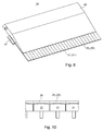
- the ink knife 26 may be carried out interrupted at least in the region of the metering edge 27, wherein in a first alternative, an over the nominal width b N integrally continuous ink knife 26 with tongue-like portions 29 i , z. B. blade sections 29 i , is formed, which are formed for example by made by the dosing ago slits.
- the ink knife 26 of several, substantially completely juxtaposed individual sections 29 i , z. B. blade sections 29 i , be formed.
- a second, preferred embodiment comprises the ink fountain 17 a over the entire nominal width b N of the ink fountain 17 - ie across the width of the ink fountain 17, on which a metered ink delivery to a co-operating ink roller 18 is provided operationally - reaching ink meter 26, which on at least this nominal size b N has a continuous metering edge 26.
- that edge of the ink blade 26, which is closest to the inking roller 18 during operation and forms with this a metering gap 42 In this embodiment, on the one hand passage through slit-like interruptions, as they may occur in the first embodiment of the ink knife 26, completely excluded.
- the "nominal width" b N here denotes that width of the ink supply device 17, which is to be designated by the manufacturer as usable inking width and / or on which, by design, a controlled ink application to the inking unit roller 18 can and / or should take place.
- the continuous or interrupted metering edge 27 then has, for example, at least or exactly this nominal diameter b N , which can then also be understood as the "effective width" of the colorimeter. Even if possibly lateral areas - for example, for fastening, transport or leadership purposes - should go beyond the Dosierkantenbreite, so should be understood in doubt, the term width b26 of the ink knife 26 whose effective width, ie the width of the effective metering edge 27 ,
- the ink blade 26 Along the width of the ink blade 26 is a plurality of in the direction of nominal diameter b N of the ink fountain 17 considered juxtaposed actuating means 31, z. B. lever 31, provided to vary the sections 29 i of the one or more color meter 26 at least in the dosing edge 27 in the respective occupied in operating position distance a i to the extent of inking device 17 to be inked by the ink fountain roller 18 and / or vary to be able to. This distance a i forms the present gap dimension a i .
- these blade sections 29 i are referred to below in the same sense as the sections 29 i or zones 29 i assigned to the adjusting means 31.
- the ink supply or ink delivery to the inking unit roller 18 is zonally adjustable, these "soft" resulting sections 29 i, in contrast to the actually separated sections 29 i of the first knife embodiment 29 i, cause smoother transitions.
- knife sections 26 i of trained with continuous metering edge 27 ink blade 26 can be used as a gap a i z.
- an effective gap a i formed by the geometric mean across the width of the above-defined fictitious portion 29 i are considered.
- a limitation of the travel is preferably provided, so that at any point of the section width, a minimum distance of z. B. falls below 0.02 mm.
- the continuous ink knife 26 is made of metal, preferably in total or at least in the region of the metering edge 27 made of a steel having a hardness of at least 55, preferably at least 60 HRC. At least in the region of the metering edge 27 comprehensive end, it has z. B. no additional coating and / or is formed homogeneously by a uniform material. Thus, it can be reground at the ends, without changing its effect and / or property. It has - over its entire width and length or at least adjoining the metering edge 27 and cooperating with the adjusting means 31 and optionally the region lying on the opposite edge region - a material thickness of 0.5 to 4 mm, in particular 1 to 3 mm up.
- actuating means 31 This can be dependent on the bending elasticity and / or the hardness of the material used and / or the dimensioning of the resulting by number and distribution of the actuating means 31 section or zone width and / or of the free, ie not by Clamping or otherwise fastening to a deformation hindered length of the ink blades 26 in its transverse to the metering edge 27 and nominal width b N extending longitudinal direction.
- the strength of the ink knife 26 is in connection with its attachment z. B. carried out so that of an actuating means 31 to the adjacent actuating means over 50% of the possible and / or approved, ie the electronically limited by the mechanics and / or the control, actuating means range ⁇ S (see, eg. Fig.
- the adjusting means 31 can basically as purely manually, z. B. via levers and / or screws, actuated adjusting means 31, or preferably by remote-controlled actuators 32, possibly also via gear parts such. B. lever and / or screws, to be actuated adjusting means 31 may be formed.
- the drive which is only indicated schematically, may preferably comprise an actuator 32 embodied as an electric motor.
- the adjusting means 31 may be basically formed arbitrarily at their end cooperating with the ink knife 26 and the relevant section 29 i .
- the adjusting means 31 comprises a section 29 i facing and closest surface whose parallel to the dosing edge 27 extending profile on a width which at least one third, preferably at least half, preferably at least two-thirds of the width of the Section 29 i corresponds to at most 0.30, preferably at most 0.20 mm at a distance to the section 29 i or the highest point varies.
- a convex profile is provided on this width, which drops away in the edge regions from the highest, the portion 29 i closest or at the first contact point away.
- such a convex profile extends over a width which corresponds entirely to the gap-shaped intermediate spaces required for the mobility, ie at least 99%, the section width, and which in the edge regions by at least 0.10 and at most 0.30 mm i falls from the highest, the portion 29 located closest to or at the first contact point away (see, for. example, Fig. 10 ).
- the ink blade 26 is here its extension in the direction of nominal diameter b N , ie in a direction parallel to the continuous or interrupted Dosierkante 27 direction as the width b26 of the ink blade 26, and its perpendicular thereto extension referred to as its length I26.
- the one- or multi-part ink knife 26 is received in the mounted state of a knife holder 28 and releasably connected thereto.
- the connection between the ink knife 26 and the knife holder 28 can in principle be made in a non-positive manner (eg by clamping) and / or in a form-fitting manner (eg by corresponding shaping or holding means).
- the farm eater 26 is clamped between two clamping legs, which form between them a clamping gap 45, which is bounded at the rear, for example by a connecting portion or connecting means.
- the nip 45 or its gap length I45 is understood to mean the length of the gap into which a color knife 26 can dip to the maximum.
- this is ready for operation on the knife holder 28, ie ready for use, mounted color knife 26 in the knife holder 28 only frictionally against movement in the longitudinal direction, d. h both against movement in the direction of the knife holder 28 into and out of this, kept. It is on his Holder side end formed without a longitudinal movement opposing positive engagement with the blade holder 28 and / or arranged without contact to a longitudinal movement opposing stop.
- the nip 45 is z. B. executed with a greater length I45, as would be required for receiving the ready-mounted colorimeter 26th
- the extension of the ink blade 26 along the metering edge 27 may be greater than its extension from the holder side to Dosierkanten medicalen end here is the former extension as its extension in the width direction or as its width b26 latter extent as its extension in the longitudinal direction or as length I26 designated.
- the thickness characterizing the thickness of the colorimeter 26 is also referred to as thickness.
- the knife holder 28 is in turn arranged via a positive and / or non-positive connection 33 releasably on the ink fountain frame 23 and / or can be arranged.
- a knife holder 28 in a direction of movement to the metering edge 27 towards limiting stop device with a frame-fixed stop 34, z. B. holder stop 34, is provided, which cooperates with a blade holder fixed stop surface 36 (see, for example, indicated in Fig. 9 With Fig. 6 ).
- the detachable connection 33 between knife holder 28 and ink fountain frame 23 in any type, for example, by screwing or other form fit.
- a fastening device 37 is provided, through which the knife holder 28 against the frame-fixed, preferably with respect to the knife holder 28 frontally arranged stop 34 is movable and / or fixed thereto.
- a connection 33 comprises a fastening device 37 in the form of a - preferably spring-biased - clamping device 37, through which the knife holder 28 is securely applied to the stop 34 provided.
- the clamping device is preferably biased in the direction of active clamping action in the case of the spring-biased design.
- the spring preload can basically be effected by an arbitrarily designed spring element, but is formed in the illustrated embodiment as a compression spring.
- the fastening device 37 comprises a mechanism 38, in particular a - preferably spring-biased - wedge drive 38 through which the knife holder 28 against the frame-fixed front stop 34 and at the same time at least against another, the knife holder 28 z. B. deck or bottom side supporting frame member 39 can be acted upon with force, so that it occupies a defined with respect to the frame 23 and / or any reproducible position in the operating state. Stopper 34 and the support surface of the frame member 39 are arranged so that they at closed connection 33, z. B. with loaded wedge drive 38, prevent movement of the knife holder 28 in any direction perpendicular to the alignment of the metering edge 27 extending direction.
- the wedge drive 38 can, for example by means of a first, the frame 23 attributable wedge 38.1, the frame side against a frame-fixed abutment 44 against dodging in a direction away from the dosing 27 direction.
- the expression 'attributable to the frame' means that the first wedge 38.1 structurally assigned to the frame 23, that is arranged on this, even if it can be mounted to perform the adjusting or clamping movement movable on this or is.
- this first wedge 38.1 acts as a first clamping element 38.1 on the side of his, preferably wedge-shaped, effective surface with a, preferably wedge-like, effective surface of a second wedge 38.2 as a second clamping element 38.2 as a wedge drive 38 formed clamping device together.
- the second clamping element 38.2 basically also attributable to the frame 23, but in particular be movably mounted at least with a component in the direction of dosing, wherein the second clamping element 38.2 presses against the knife holder 28.
- it may instead be provided on the knife holder 38.2, which may then be executed as part of or as an attachment to the knife holder 28.
- the knife holder 28 is designed in the manner of an insert, which with at least one lower part in a corresponding recess 43 in an otherwise z. B. substantially closed top of the one- or multi-part frame 23 is used.
- the stop 34 forms the boundary of the depression, in the opposite direction of the z. B. the wedge drive 38 supporting abutment 44.
- the latter can form as an appropriately shaped part of the adjoining frame part or in the manner of a back strip 44 an optionally releasable frame part.
- the supporting surface forming and / or at least comprehensive frame part 39 is in this case provided in the front and back side by the stop 34 and the abutment 44 limited recess 43.
- the fastening device 37 can be a cross-locking - z. B. in the manner of a bayonet - include, which prior to removal and / or, if necessary, depending on the last occupied position of the transverse locking, before the onset of the knife holder 28, first a transverse movement, d. H. a to the dosing 27 substantially parallel movement of a cross bar 46 requires.
- the frame 23 associated wedge 38.1 or wedges 38.1 of the wedge drive 38 is connected to the cross bar 46 and is with this by the transverse movement either in Engaged with the or the knife holder fixed wedge 38.2 or wedges 38.2 or spent out of engagement.
- a corresponding, reachable by the operator input or attack device 46.1 may be provided.
- this can for the embodiment with multiple wedge drives 38 and wedge pairs 38.1; In principle, it may be advantageous to simultaneously actuate the wedge drives 38 by moving the strip 46 in one direction with a component perpendicular to the transverse direction.
- a frame-fixed and / or on the bar 46 medium or directly connected wedge selectively lifting and lowering drive 54 is provided. This can basically be carried out in any desired manner, for example as a screw drive, but preferably as an eccentric drive 54.
- the drive is made by turning an on or multi-part, for example, in the frame part 39, in particular in the abutment 44 forming part of the frame member 39, pivotally mounted shaft 54.1, which a medium or directly with one or more of the wedge drives 38, in particular with the plurality of wedge drives 38 associated bar 46, cooperating eccentricity 54.2 includes.
- This eccentricity 54.2 may be formed by the shape of the shaft 54.1 itself or by an eccentric disc 54.2 connected thereto.
- the one- or multi-part shaft 54.1 includes, for example, in an accessible from outside the frame part 39 area an attack device 54.3, which, for example, in the form of a handle directly, or via a tool, for. B. an engaging in a corresponding driving profile Allen key, is pivotable.
- a first clamping element 38.1 is provided on the frame 23, which is such movably arranged on the frame 23 and is movable by a drive mechanism 54, that for closing the fastening device 37 causes the first clamping element 38.1 by moving a movement of a second clamping element 38.2 and / or the inserted knife holder 28 with at least one component of movement in the direction dosing 27, wherein z. B.
- the second clamping element 38.2 only a part or an attachment of the knife holder 28 or else also movably arranged on the frame 23 and may be arranged in the inserted state of the knife holder 28 cooperating with this.
- the first clamping element 38.1 is movable away from the dosing edge 27 by the drive mechanism 54 with at least one movement component, whereby the clamping connection between the first clamping element 38.1 and the second clamping element 38.2 and / or the inserted knife holder 28 is relieved.
- the clamping element 38.1 may be formed in a simplified embodiment by a part of the drive mechanism 54 itself, for example, by a cooperating with the knife holder threaded part, screw or Screw head of a drive mechanism 54 designed as a screw drive 54.
- the detachable connection between ink knife 26 and knife holder 28 may be basically arbitrary, it is preferably designed in the manner of a clamping connection 57.
- the connection is preferably carried out such that the ink knife (26 and the holding and / or clamping means comprising comprehensive blade holders 28 are formed corresponding to each other such that the ink knife 28, in particular its opposite end of the metering edge 27, continuously within at least a range of two in the longitudinal direction significantly, ie, for example, at least 1 mm, preferably at least 3 mm,
- the ink blade 28, with its end opposite the dosing edge 27, viewed in the longitudinal direction can thus be arranged and fixed continuously in different positions on the knife holder 28 within the aforementioned setting range ,
- the nip 45 and the clamping connection 57 can basically between two legs of a same clamping body or between clamping legs of two clamping body 47; 48 of the knife holder 28 may be formed, which, for example, in a self-locking design by actuation of an actuating means 49 from a existing by residual stress narrower clamping position in an open position or as provided here vice versa from a position open in the tension-free state in a clamping position can be connected.
- clamping body 47 For example, designed as a clamping bar 47 clamping body 47 is provided, on which the ink knife 26, for example, by a running in the knife longitudinal direction slot or a slot provided behind the slot cross-driving screw drive, z. B. screw (for example, using a clamping plate, eg., Washer) is clamped in a desired relative position or is.
- the ink knife 26 is clamped by the clamping legs of a running as a cover strip 48 clamping body 48 by this clamping leg by, for example, a screw 49, z. B. screw 49, is tightened in the direction of the clamping leg of the terminal block 47.
- the two clamping legs of the clamping and cover strip 47; 48 between them the nip 45 from.
- the terminal block 47 in the o. G. Be arranged recess 43 and / or include the knife holder side wedge.
- clamping connection 57 with an excess in the length of the nip 45 in the region of the holder-side end of the ink knife 26 can be positioned in the longitudinal direction in a varying position on the knife holder 28.
- the nip 45 is preferably designed with an oversize in its length, so that 26 operatively mounted colorimeter this non-end, ie with its dosing edge 27 opposite end abuts in the nip 45. In particular, this should not strike against a rigid, knife holder fixed path limitation in the manner of an at least one-sided positive connection, which z. B. at loosened Traction would prohibit any further movement into the gap relentlessly. Below, however, for example, no yielding, z. B. spring-loaded or elastic trained Schukantenabstützung be understood which z. B.
- nip 45 can here in extension to the exemplified embodiment with an extension over much of the width b26 and with a cross-sectional actually substantially gap-shaped geometry in a broader sense, any expression of an arrangement of one or more pairs of opposing clamping surfaces are understood between which the ink knife 26 is inserted and clamped.
- length I45 of the nip 45 can be understood in this expanded meaning then that length on which the ink knife 26 is missing with its holder-side end between the clamping surfaces in the knife holder 26 in the longitudinal direction of the ink blade 26 without an end-side striking the knife holder 28.
- this length of the nip 45 would be virtually unlimited and thus in any case greater than required for an operationally mounted ink knife 26.
- this length relates to the length at which a first impact occurs on movement in this longitudinal direction at any point along the entire width b26 of the colorimeter 26. This represents in reverse consideration so the length of an undisturbed insertion between the pairs of clamping surfaces.
- the ink fountain 17 or its frame 23 may include on the ink roller 18 to be inked ink fountain side a front panel 52 which z. B. in turn one For example, seal can wear from an elastic and / or compressible material.
- a cross member 56 may be provided, which is mounted in the above-mentioned manner fixed or pivotable on the side frames 24 and which carries the remaining parts of the ink fountain 17 or frame 23.
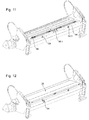
- the mounting device 61 is designed for the defined assembly of a metering edge 27 comprising ink blade 28, as may preferably be formed in an embodiment set forth above, on a knife holder 28, as he may preferably be formed in an embodiment set forth above.
- the mounting device 61 comprises a holding section 62 with a holding device, on or in which the knife holder 28 or at least a part of a multi-part knife holder 28, for. B. an o. G. Terminal block 47, in a defined position with a z in. B. above-mentioned manner formed holder-side stop surface 36 against a movement of the knife holder 28 in the direction of the colorimeter 26 to be mounted limiting, with respect to the mounting device 61 fixed to the frame holder stop 63 is used.
- the mounting device 61 comprises a rigid one-piece or multi-part frame 64 of the mounting device 61 with the holding device of the holding portion 62nd connected abutment portion 66, on or in which the one-piece to be mounted (see, for. Fig. 14 ) or multipart (see eg Fig. 16 ) Color meter 28 with its metering edge 27; 27 i against a knife stop 67 can be applied.
- Shaping and relative position between holding device with holder stop 63 and abutment portion 66 with knife stop 67 are set in the manner of an assembly jig so that the knife holder used in the holder 28 and the knife stop 67 applied ink knife 26 already in unconnected state at least in a direction perpendicular to the dosing 27 Longitudinal direction of the ink blade 26 considered a desired for the assembly and defined by the mounting device 61 and reproducible relative position to each other.
- the knife stop 76 is preferably variable with respect to its distance from the holder stop 63, in particular at least adjustable, formed and / or arranged on the frame 64.
- the knife holder 28 corresponds to the o. G. one or more parts knife holder 28 and / or comprises in manner mentioned above manner holding means for fixing the one or more parts color blade 26, in particular in the form of a clamping gap 45 described above, a clamping connection 57 with, for example, a clamping and a cover strip 57 ; 58th
- the ink knife 26 and the holding means comprehensive knife holder 28 are again in a manner set forth above with each other with an excess in the nip length corresponding formed that the ink knife 28 in the longitudinal direction continuously within at least a range of two in the longitudinal direction significantly, ie, for. B. at least 3 mm, beastandeter relative positions on the knife holder 28 is anorden- and clamped.
- the above stated here is applicable accordingly.
- the knife holder 28 is preferably designed in several parts and comprises two strips 57; 58, z. B. a terminal strip 57 and a cover strip 58, between which the - preferably formed in the longitudinal direction with excess - clamping gap 45 is formed, in which the one- or multi-part ink knife 26 is clamped in the assembled state.
- the ink knife 26 may comprise a plurality of spaced apart in the transverse direction of the ink blade 26, extending in the longitudinal direction of the ink blade 26 slots or end-side slots, which are penetrated in the clamped state of each holding means, such as a sleeve or screw 49.
- each holding means such as a sleeve or screw 49.
- the ink knife 26 is merely clamped without having slots or elongated holes which are penetrated by holding means in the mounted state.
- the trained as a screw 49 holding means 49 then preferably attacks outside of the holder-side end of the ink blade 26 on the two legs of the one or more multi-part knife holder 26 to clamp between these in the mounted state, the ink knife 26.
- the mounting device 61 includes for releasable connection between fair holder 28 or a part, for example, the cover or preferably terminal strip 57, the multi-part knife holder 28 and the mounting device 61 in the region of its holding portion 62, a fastening device 68, preferably a clamping device 68, through which the knife holder 28 or the one part, for example, the cover or preferably clamping bar 57, the multi-part knife holder 28 against the respect.
- the mounting device 61 fixed to the frame, a the knife holder 28 and the one part in a direction of movement to the knife stop 67 towards limiting stop 63 applied and / or can be fixed to these.
- the fastening device 68 comprises a mechanism 69, in particular a wedge drive 69, through which the knife holder 28 against the frame-fixed front stop 63 and at the same time against at least one another, the knife holder 28 z.
- deck or bottom defined support frame member 71 can be acted upon with force, so that he in fixed state assumes a defined with respect to the frame 64 and / or any reproducible position. The reproducibility of the situation can by a relative transverse movement between terminal strip 57 or cover strip 58 preventing or at least severely limiting stop device, for. B.
- the positioning pin 65 may be provided in the cover strip 58 or preferably in the terminal strip 57 (eg. Fig. 13 ).
- Stop 63 and the support surface of the frame part 71 are arranged such that they are closed when connected, z. B. with loaded wedge drive 69, a movement of the knife holder 28 and its one part, z. B. preferably the terminal strip 57, in any direction perpendicular to the alignment of the metering edge 27 prevent direction.
- the wedge drive 69 comprises, for example, the wedge assigned to the knife holder 28, which cooperates with a wedge 72 attributable to the mounting device 61.
- the wedge 72 attributable to the mounting device 61 can be designed, for example, in the manner of a frusto-conical disk 72, which can be moved axially by a screw drive 73.
- a frame 64 engages in a frame 64, in particular the frame part 71 provided thread a screw on which rotatably or possibly rotatably coaxial with the disc 72 is arranged.
- the screw is connected to the pivoting, for example, with at least one handle 74.
- an optionally adjustable side stop 76 may be provided on one side, against which the ink knife 26 by a arranged on the opposite side drive 77, z. B. clamping and / or wedge drive 77, can be fixed.
- the frame 64 may be mounted on a solid base or on a pedestal 78.
- a system for feeding and metering ink into an inking unit 12 of a printing press can thus have an ink feed device 19 and a mounting device 61 comprising, wherein the Farbzu Genevavoriques 19 comprises a frame 23 to which a knife holder 28 is detachably arranged, which carries in the mounted state, a one- or multi-part ink blade 26, whose front end protrudes beyond the knife holder 28 and forms a continuous or interrupted metering edge 27, wherein the knife holder 28 by means of a stop device in a defined position and position releasably on the frame 23 can be arranged.
- the mounting device 61 comprises a frame 64 on which the blade holder 28 can be detachably arranged for mounting the ink blade 26, the blade holder 28 being detachably mountable on the frame 61 by means of a stop device in a defined relative position and position relative to a blade stop 67. wherein the shape and relative position between the abutment device for the mounting device 61 and the knife stop 67 in the manner of an assembly jig are set so that the knife holder 28 and the ink knife 26 in a still unconnected state occupy a defined and reproducible relative position to each other, and in which they then together are connectable.
- the ink supply device 19 and the assembly device 61 of the system may be designed in the manner described above.
- the one- or multi-part ink knife 26 may be such.
- FIGS. 17 and 18 illustrated having a nominal width b N corresponding width b26, wherein the sections 26 i of the continuous or multi-part ink blade 26 in total form the zonal adjustable inking unit width.
- a z. B. L-shaped sealing element 79, z.
- the sealing piece 79 is z. B. - such as in Fig. 18 indicated by double arrow - in the direction of the nominal diameter b N of the ink supply device 17 at least slightly movable and z. B. by inserting the one or more parts Side wall 41 via a corresponding clamping mechanism laterally towards the ink knife 26 to this movable.
- the clamping mechanism not shown here, for example, is designed such that the one- or multi-part side wall is supported on its outer side when inserted into the Farbzu 1500vorides on an outer frame member 81 of the frame 23 and experiences a force inwardly towards the ink knife 26 out.
- the Farmesser 26 When inserted side wall 41, the Farmesser 26 is then laterally sealed over the sealing element 79 to the side wall 41.
- the blade 26 comprising the color knife 26 is on and removable as a result of the transversely movable sealing elements without lateral jamming.
- the ink knife 26 at least in the region of the metering edge 27 with a width greater than the nominal size bN B26, z. B. on both sides by 2 to 10 mm wider, be formed and in installation position in the respective edge region with the supernatant on a frame-fixed support 82, z. B. guide bar 82, come to rest (see, for. Fig. 19 and 17 ).
- the guide bar 82 may in this case be firmly connected to the outer frame member 81 and / or arranged such that the overlying part of the ink knife 26 in the operating position of the ink supply 17 only a slight gap of z. B. at most 0.08 mm, preferably at most 0.06 mm, with the ink fountain roller 18 is formed.
- the color knife 26 comprehensive knife holder 28 is particularly easy to install and remove without lateral jamming.
- the knife holder 28 carrying the ink knife 26, for example is first removed from the ink feed device 19 together with the ink knife 26.
- the effective for color dosing dosage 27 can now z. B. be renewed by - after removal of the knife holder 238 from the Farbzu Foodvoriques 17 which still on Knife holder 28 arranged or already dissolved by this ink knife 26 is sanded on the metering edge 27 comprehensive end, whereby in the region of this end a renewed by refurbishment metering edge 27 'is formed.
- an end may be up to 10 times, preferably up to 20 times each z. B. at least 0.5 mm, in particular be sharpened by 0.5 to 1.5 mm.
- the rotation and regrinding can also be combined to renew the dosing edge, wherein z. B. after exhausting the possibilities provided by turning a grinding can be done at one or both ends. Subsequently, the metering edge 27 can then be renewed again by turning.
- the relative position between knife holder 28 and ink blade 26 is readjusted with respect to the position of the new metering edge 27 'with dissolved connection and subsequently made the connection with adjusted relative position. Finally, the knife holder 28 is used together with the color knife 26 in a defined position and position in the Farbzu Switzerlandvoriques 19 again and fixed in this.
- the relative position between the knife holder 28 and ink blade 26 with respect to the position of the new metering edge 27 'with dissolved connection by using an effective in the manner of an assembly jig mounting device, in particular by using a mounting device 61 as set forth in more detail above, adjusted.
- the blade holder 28 is positionally and positionally fixed on the mounting device 61 via a stop device and the not yet associated with this color blade 26 on the knife stop 67. After investment, the one- or multi-part ink knife 26 and the knife holder 28 are positively and / or frictionally connected together.
- the adjusting means 31 have a significant, z. B. by at least 20% larger actuating means setting range .DELTA.S, as he for the placement of the relevant blade section 26 i by a maximum travel S M between a zero position and a desired maximum position, ie a maximum gap or distance a iM to the extent of the ink supply device 17 to be inked inking roller 18, would be required.
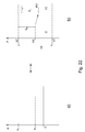
- the zeroing of the gap is done in such a way that in this zero position of the blade portion 29 i the relevant actuating means 31 in a zero position P0 are which to both Setting range ends s1; s2 of the actuating means setting range ⁇ S significant, z. B. by at least 20% of the actuating means range, is spaced.
- a checking of the gap dimension in the blade sections 29 i takes place with adjusting means 31 in zero position P0.
- the readjustment actuates the adjusting means 31 assigned to the relevant knife section 29 i in such a direction that the desired gap dimension a i0 representing the closed position is restored.
- the position P adopted after the readjustment of the adjusting means 31 is set as a new zero position P0 'of the actuating means 31.
- the gap dimension a i0 representing the closed position is preferably greater than 0.00 mm in order to prevent unnecessarily high abrasion.
- This gap dimension a i0 is preferably at least 0.02 and at most 0.08 mm, preferably 0.04 to 0.06 mm.
Landscapes
- Engineering & Computer Science (AREA)
- Mechanical Engineering (AREA)
- Inking, Control Or Cleaning Of Printing Machines (AREA)
- Rotary Presses (AREA)
- Coating Apparatus (AREA)
- Auxiliary Devices For And Details Of Packaging Control (AREA)
Applications Claiming Priority (3)
| Application Number | Priority Date | Filing Date | Title |
|---|---|---|---|
| DE102013225691.4A DE102013225691B4 (de) | 2013-12-12 | 2013-12-12 | System zum Zuführen und Dosieren von Druckfarbe in ein Farbwerk einer Druckmaschine sowie Verfahren zum Erneuern einer zur Farbdosierung wirksamen Dosierkante |
| PCT/EP2014/069692 WO2015086183A2 (fr) | 2013-12-12 | 2014-09-16 | Dispositif d'alimentation en encre pourvu d'un colorimètre |
| EP14771254.1A EP3079910B1 (fr) | 2013-12-12 | 2014-09-16 | Dispositif d'alimentation en encre pourvu d'une lame d'encrier |
Related Parent Applications (2)
| Application Number | Title | Priority Date | Filing Date |
|---|---|---|---|
| EP14771254.1A Division-Into EP3079910B1 (fr) | 2013-12-12 | 2014-09-16 | Dispositif d'alimentation en encre pourvu d'une lame d'encrier |
| EP14771254.1A Division EP3079910B1 (fr) | 2013-12-12 | 2014-09-16 | Dispositif d'alimentation en encre pourvu d'une lame d'encrier |
Publications (2)
| Publication Number | Publication Date |
|---|---|
| EP3156233A1 true EP3156233A1 (fr) | 2017-04-19 |
| EP3156233B1 EP3156233B1 (fr) | 2018-07-25 |
Family
ID=51582373
Family Applications (2)
| Application Number | Title | Priority Date | Filing Date |
|---|---|---|---|
| EP16171224.5A Not-in-force EP3156233B1 (fr) | 2013-12-12 | 2014-09-16 | Système d'alimentation et de dosage d'encre dans un mécanisme d'encrage d'une imprimante |
| EP14771254.1A Active EP3079910B1 (fr) | 2013-12-12 | 2014-09-16 | Dispositif d'alimentation en encre pourvu d'une lame d'encrier |
Family Applications After (1)
| Application Number | Title | Priority Date | Filing Date |
|---|---|---|---|
| EP14771254.1A Active EP3079910B1 (fr) | 2013-12-12 | 2014-09-16 | Dispositif d'alimentation en encre pourvu d'une lame d'encrier |
Country Status (7)
| Country | Link |
|---|---|
| US (1) | US9643399B2 (fr) |
| EP (2) | EP3156233B1 (fr) |
| JP (1) | JP6177443B2 (fr) |
| CN (1) | CN105813847B (fr) |
| DE (1) | DE102013225691B4 (fr) |
| RU (1) | RU2667814C1 (fr) |
| WO (1) | WO2015086183A2 (fr) |
Families Citing this family (6)
| Publication number | Priority date | Publication date | Assignee | Title |
|---|---|---|---|---|
| ITUA20163914A1 (it) * | 2016-05-30 | 2017-11-30 | Celmacch Group S R L | Racla per macchina da stampa e suo montaggio |
| US20200001596A1 (en) * | 2017-06-01 | 2020-01-02 | I.Mer Co., Ltd. | Device for Cleaning Ink Reservoir, Printing Machine, and Method for Cleaning Ink Reservoir |
| DE102017222094A1 (de) | 2017-12-06 | 2019-06-06 | Koenig & Bauer Ag | Druckwerk einer Druckmaschine und Verfahren zum Betreiben eines Druckwerkes einer Druckmaschine |
| DE102018130283A1 (de) * | 2018-11-29 | 2020-06-04 | Koenig & Bauer Ag | Bogentiefdruckmaschine mit mindestens einem Druckwerk zum Bedrucken von Druckbogen |
| US11440312B2 (en) * | 2019-02-05 | 2022-09-13 | Koenig & Bauer Ag | Gravure printing units for printing onto substrates by a gravure printing method |
| TWI694007B (zh) | 2019-06-06 | 2020-05-21 | 至善實業股份有限公司 | 凹版印刷機之同向封閉式刮刀裝置 |
Citations (14)
| Publication number | Priority date | Publication date | Assignee | Title |
|---|---|---|---|---|
| DE1225205B (de) * | 1964-09-08 | 1966-09-22 | Winkler Maschf | Rakelvorrichtung fuer eine Rotationstiefdruckmaschine |
| DE6901424U (de) | 1968-01-15 | 1969-10-02 | Hoe & Co R | Einrichtung zur genauen einstellung eines rakels einer druckpresse |
| DE2709194A1 (de) | 1977-03-03 | 1978-09-07 | Rolf Meyer | Vorrichtung zum einsetzen einer rakel in einen rakelhalter |
| DE2834932A1 (de) | 1978-08-09 | 1980-02-21 | Adriano Galbiati | Waermepumpe |
| DE2951653A1 (de) * | 1979-12-21 | 1981-07-02 | M.A.N.- Roland Druckmaschinen AG, 6050 Offenbach | Vorrichtung zum dosieren von farbe auf der farbkastenwalze eines farbwerks fuer druckmaschinen |
| DE3613806A1 (de) | 1986-04-24 | 1987-10-29 | Steuber Heinrich | Farbmesseranordnung |
| DE3834932A1 (de) | 1988-10-13 | 1990-04-19 | Herbert Ott | Rakelhalterung sowie hierfuer geeignete rakel |
| EP0453872A1 (fr) | 1990-04-26 | 1991-10-30 | MAN Roland Druckmaschinen AG | Dispositif de lames d'encrier |
| DE9109785U1 (de) | 1991-08-07 | 1992-09-17 | J.M. Voith Gmbh, 7920 Heidenheim | Rakelvorrichtung mit Rakelbalken |
| DE4240642A1 (de) | 1992-12-03 | 1994-06-09 | Koenig & Bauer Ag | Farbmesser-Lamelle und Farbmesserträger für einen Farbkasten einer Rotationsdruckmaschine |
| EP1057629A2 (fr) | 1999-06-03 | 2000-12-06 | Mitsubishi Heavy Industries, Ltd. | Système d'alimentation en encre et son vis de réglage du débit d'encre |
| WO2002016138A1 (fr) | 2000-08-23 | 2002-02-28 | Cti-Systems Gmbh | Modules constitues de lamelles de colorimetre modulaire et de sections de traverse |
| DE602005002142T2 (de) | 2004-04-22 | 2008-03-06 | Kba-Giori S.A. | Tintenzuführungsvorrichtung für druckmaschine |
| WO2011077350A1 (fr) | 2009-12-22 | 2011-06-30 | Kba-Notasys Sa | Presse pour impression en taille douce avec cylindre d'impression en taille douce |
Family Cites Families (14)
| Publication number | Priority date | Publication date | Assignee | Title |
|---|---|---|---|---|
| SE333577B (fr) | 1969-02-12 | 1971-03-22 | Winkler Fallert & Co Maschf | |
| US5233922A (en) * | 1991-01-10 | 1993-08-10 | Belgium Tool And Die Company | Ink fountain for a can coater |
| DE4410452C2 (de) * | 1994-03-25 | 1996-08-29 | Roland Man Druckmasch | Justiereinrichtung für eine Rakel |
| DE19525529C1 (de) * | 1995-07-13 | 1996-06-05 | Koenig & Bauer Albert Ag | Verfahren zur Montage einer Dosiereinrichtung in einer Rotationsdruckmaschine |
| JP2964246B1 (ja) * | 1998-07-27 | 1999-10-18 | 株式会社東京機械製作所 | キーレス印刷機のインキ貯留装置 |
| JP3189893B2 (ja) * | 1998-09-08 | 2001-07-16 | 株式会社東京機械製作所 | インキ壺装置におけるインキ出し隙間調整装置 |
| JP3981332B2 (ja) * | 2003-01-23 | 2007-09-26 | 株式会社桜井グラフィックシステムズ | 印刷機のインキ供給装置 |
| US7032511B2 (en) * | 2003-04-16 | 2006-04-25 | A.B. Dick Company | Fountain ink feed system |
| JP4723221B2 (ja) * | 2004-10-04 | 2011-07-13 | 有限会社ベアテック | ドクタブレード取付装置 |
| FI121390B (fi) * | 2009-03-31 | 2010-10-29 | Runtech Systems Oy | Paperikoneen kaavinlaitteisto ja menetelmä paperikoneen kaavinlaitteiston tehostamiseksi |
| CN102049897A (zh) * | 2009-11-02 | 2011-05-11 | 汤维江 | 凹版印刷机刮刀座 |
| CN102139559A (zh) * | 2010-02-01 | 2011-08-03 | 海德堡印刷机械股份公司 | 印刷机的油墨配量装置 |
| US20110189378A1 (en) * | 2010-02-04 | 2011-08-04 | Moon So-Ii | Apparatus and method for coating a functional layer |
| FI126705B (fi) * | 2014-09-09 | 2017-04-13 | Valmet Technologies Inc | Kaavinlaitteisto rainanmuodostuskoneelle liikkuvan pinnan kaapimiseksi ja vastaava pidikeosa ja teräpidin |
-
2013
- 2013-12-12 DE DE102013225691.4A patent/DE102013225691B4/de not_active Expired - Fee Related
-
2014
- 2014-09-16 EP EP16171224.5A patent/EP3156233B1/fr not_active Not-in-force
- 2014-09-16 EP EP14771254.1A patent/EP3079910B1/fr active Active
- 2014-09-16 US US15/037,373 patent/US9643399B2/en active Active
- 2014-09-16 JP JP2016539203A patent/JP6177443B2/ja active Active
- 2014-09-16 RU RU2016127860A patent/RU2667814C1/ru active
- 2014-09-16 WO PCT/EP2014/069692 patent/WO2015086183A2/fr not_active Ceased
- 2014-09-16 CN CN201480067638.5A patent/CN105813847B/zh not_active Expired - Fee Related
Patent Citations (14)
| Publication number | Priority date | Publication date | Assignee | Title |
|---|---|---|---|---|
| DE1225205B (de) * | 1964-09-08 | 1966-09-22 | Winkler Maschf | Rakelvorrichtung fuer eine Rotationstiefdruckmaschine |
| DE6901424U (de) | 1968-01-15 | 1969-10-02 | Hoe & Co R | Einrichtung zur genauen einstellung eines rakels einer druckpresse |
| DE2709194A1 (de) | 1977-03-03 | 1978-09-07 | Rolf Meyer | Vorrichtung zum einsetzen einer rakel in einen rakelhalter |
| DE2834932A1 (de) | 1978-08-09 | 1980-02-21 | Adriano Galbiati | Waermepumpe |
| DE2951653A1 (de) * | 1979-12-21 | 1981-07-02 | M.A.N.- Roland Druckmaschinen AG, 6050 Offenbach | Vorrichtung zum dosieren von farbe auf der farbkastenwalze eines farbwerks fuer druckmaschinen |
| DE3613806A1 (de) | 1986-04-24 | 1987-10-29 | Steuber Heinrich | Farbmesseranordnung |
| DE3834932A1 (de) | 1988-10-13 | 1990-04-19 | Herbert Ott | Rakelhalterung sowie hierfuer geeignete rakel |
| EP0453872A1 (fr) | 1990-04-26 | 1991-10-30 | MAN Roland Druckmaschinen AG | Dispositif de lames d'encrier |
| DE9109785U1 (de) | 1991-08-07 | 1992-09-17 | J.M. Voith Gmbh, 7920 Heidenheim | Rakelvorrichtung mit Rakelbalken |
| DE4240642A1 (de) | 1992-12-03 | 1994-06-09 | Koenig & Bauer Ag | Farbmesser-Lamelle und Farbmesserträger für einen Farbkasten einer Rotationsdruckmaschine |
| EP1057629A2 (fr) | 1999-06-03 | 2000-12-06 | Mitsubishi Heavy Industries, Ltd. | Système d'alimentation en encre et son vis de réglage du débit d'encre |
| WO2002016138A1 (fr) | 2000-08-23 | 2002-02-28 | Cti-Systems Gmbh | Modules constitues de lamelles de colorimetre modulaire et de sections de traverse |
| DE602005002142T2 (de) | 2004-04-22 | 2008-03-06 | Kba-Giori S.A. | Tintenzuführungsvorrichtung für druckmaschine |
| WO2011077350A1 (fr) | 2009-12-22 | 2011-06-30 | Kba-Notasys Sa | Presse pour impression en taille douce avec cylindre d'impression en taille douce |
Also Published As
| Publication number | Publication date |
|---|---|
| WO2015086183A2 (fr) | 2015-06-18 |
| EP3079910A2 (fr) | 2016-10-19 |
| WO2015086183A3 (fr) | 2015-10-29 |
| CN105813847B (zh) | 2017-08-04 |
| US20160279926A1 (en) | 2016-09-29 |
| JP6177443B2 (ja) | 2017-08-09 |
| EP3079910B1 (fr) | 2020-01-22 |
| JP2016539829A (ja) | 2016-12-22 |
| US9643399B2 (en) | 2017-05-09 |
| RU2667814C1 (ru) | 2018-09-24 |
| EP3156233B1 (fr) | 2018-07-25 |
| DE102013225691A1 (de) | 2015-06-18 |
| CN105813847A (zh) | 2016-07-27 |
| DE102013225691B4 (de) | 2017-11-16 |
Similar Documents
| Publication | Publication Date | Title |
|---|---|---|
| EP3156233B1 (fr) | Système d'alimentation et de dosage d'encre dans un mécanisme d'encrage d'une imprimante | |
| EP0061581B2 (fr) | Ensemble de rouleaux pouvant être appliqué sur le cylindre de plaque d'une machine d'impression offset ou typographique | |
| DE4218422C2 (de) | Bogen-Offsetrotationsdruckmaschine mit herausnehmbarem Eindruck- oder Veredelungswerk | |
| DE2711553A1 (de) | Farbkasten fuer offset- oder hochdruckmaschinen | |
| DE2334151A1 (de) | Messerring fuer zerspanungsmaschinen, im besonderen fuer holzzerspaner | |
| DE3705194A1 (de) | Farbwerk | |
| DE8028609U1 (de) | Einrichtung zur farbdosierung in einer druckmaschine, insbesondere einer offset-bogenmaschine | |
| EP1467865A2 (fr) | Dispositif d'encrage d'un rouleau | |
| EP2204284B1 (fr) | Séparateur de zones d'encrages d'encrier | |
| DE3714936A1 (de) | Farbwerk fuer eine druckmaschine | |
| CH685380A5 (de) | Rotationsdruckmaschine. | |
| EP2298554B1 (fr) | Imprimante pour l'impression de produits imprimés | |
| DE3130825C2 (de) | Verfahren zum Betrieb einer Mehrfarben-Rollenrotationsoffsetdruckmaschine und Mehrfarben-Rollenrotationsoffsetdruckmaschine zur Durchführung des Verfahrens | |
| DE19543494C1 (de) | Einstellvorrichtung für Druckwerkzylinder | |
| DE4340079C2 (de) | Offset-Druckmaschine mit einer Numeriereinheit | |
| DE60121503T2 (de) | Farbvorrichtung für eine Rotationsdruckmaschine | |
| EP2045077B1 (fr) | Dispositif d'encrage d'un rouleau d'encrage d'une machine d'impression rotative | |
| DE582509C (de) | Farbkastenwalze fuer Farbwerke von Druckmaschinen aller Art | |
| DE3109977A1 (de) | "sammeldruck-rotationsmaschinendruckwerk fuer wertpapierdruck" | |
| DE520864C (de) | Bogenanleger fuer Druckmaschinen o. dgl. mit schwingenden Greifern | |
| EP1620263A1 (fr) | Presse | |
| DE102007006062B3 (de) | Umrüstbares Druckwerk | |
| DE102011085563B4 (de) | Bogenverarbeitungsmaschine mit einer Greifereinrichtung | |
| EP2581226B1 (fr) | Presse et procédé de positionnement d'au moins un cylindre d'encrage | |
| DE102020101453A1 (de) | Antriebsvorrichtung zum Antreiben zumindest einer Reibwalze, Druckmaschine mit zumindest einem Farbwerk sowie Verfahren zum Antreiben zumindest einer Reibwalze |
Legal Events
| Date | Code | Title | Description |
|---|---|---|---|
| PUAI | Public reference made under article 153(3) epc to a published international application that has entered the european phase |
Free format text: ORIGINAL CODE: 0009012 |
|
| AC | Divisional application: reference to earlier application |
Ref document number: 3079910 Country of ref document: EP Kind code of ref document: P |
|
| AK | Designated contracting states |
Kind code of ref document: A1 Designated state(s): AL AT BE BG CH CY CZ DE DK EE ES FI FR GB GR HR HU IE IS IT LI LT LU LV MC MK MT NL NO PL PT RO RS SE SI SK SM TR |
|
| AX | Request for extension of the european patent |
Extension state: BA ME |
|
| 17P | Request for examination filed |
Effective date: 20170324 |
|
| GRAP | Despatch of communication of intention to grant a patent |
Free format text: ORIGINAL CODE: EPIDOSNIGR1 |
|
| INTG | Intention to grant announced |
Effective date: 20180328 |
|
| GRAS | Grant fee paid |
Free format text: ORIGINAL CODE: EPIDOSNIGR3 |
|
| GRAA | (expected) grant |
Free format text: ORIGINAL CODE: 0009210 |
|
| AC | Divisional application: reference to earlier application |
Ref document number: 3079910 Country of ref document: EP Kind code of ref document: P |
|
| AK | Designated contracting states |
Kind code of ref document: B1 Designated state(s): AL AT BE BG CH CY CZ DE DK EE ES FI FR GB GR HR HU IE IS IT LI LT LU LV MC MK MT NL NO PL PT RO RS SE SI SK SM TR |
|
| REG | Reference to a national code |
Ref country code: GB Ref legal event code: FG4D Free format text: NOT ENGLISH |
|
| REG | Reference to a national code |
Ref country code: CH Ref legal event code: EP |
|
| REG | Reference to a national code |
Ref country code: AT Ref legal event code: REF Ref document number: 1021319 Country of ref document: AT Kind code of ref document: T Effective date: 20180815 |
|
| REG | Reference to a national code |
Ref country code: IE Ref legal event code: FG4D Free format text: LANGUAGE OF EP DOCUMENT: GERMAN |
|
| REG | Reference to a national code |
Ref country code: DE Ref legal event code: R096 Ref document number: 502014009000 Country of ref document: DE |
|
| REG | Reference to a national code |
Ref country code: FR Ref legal event code: PLFP Year of fee payment: 5 |
|
| REG | Reference to a national code |
Ref country code: NL Ref legal event code: MP Effective date: 20180725 |
|
| REG | Reference to a national code |
Ref country code: LT Ref legal event code: MG4D |
|
| PG25 | Lapsed in a contracting state [announced via postgrant information from national office to epo] |
Ref country code: NL Free format text: LAPSE BECAUSE OF FAILURE TO SUBMIT A TRANSLATION OF THE DESCRIPTION OR TO PAY THE FEE WITHIN THE PRESCRIBED TIME-LIMIT Effective date: 20180725 |
|
| PG25 | Lapsed in a contracting state [announced via postgrant information from national office to epo] |
Ref country code: PL Free format text: LAPSE BECAUSE OF FAILURE TO SUBMIT A TRANSLATION OF THE DESCRIPTION OR TO PAY THE FEE WITHIN THE PRESCRIBED TIME-LIMIT Effective date: 20180725 Ref country code: LT Free format text: LAPSE BECAUSE OF FAILURE TO SUBMIT A TRANSLATION OF THE DESCRIPTION OR TO PAY THE FEE WITHIN THE PRESCRIBED TIME-LIMIT Effective date: 20180725 Ref country code: RS Free format text: LAPSE BECAUSE OF FAILURE TO SUBMIT A TRANSLATION OF THE DESCRIPTION OR TO PAY THE FEE WITHIN THE PRESCRIBED TIME-LIMIT Effective date: 20180725 Ref country code: IS Free format text: LAPSE BECAUSE OF FAILURE TO SUBMIT A TRANSLATION OF THE DESCRIPTION OR TO PAY THE FEE WITHIN THE PRESCRIBED TIME-LIMIT Effective date: 20181125 Ref country code: NO Free format text: LAPSE BECAUSE OF FAILURE TO SUBMIT A TRANSLATION OF THE DESCRIPTION OR TO PAY THE FEE WITHIN THE PRESCRIBED TIME-LIMIT Effective date: 20181025 Ref country code: GR Free format text: LAPSE BECAUSE OF FAILURE TO SUBMIT A TRANSLATION OF THE DESCRIPTION OR TO PAY THE FEE WITHIN THE PRESCRIBED TIME-LIMIT Effective date: 20181026 Ref country code: SE Free format text: LAPSE BECAUSE OF FAILURE TO SUBMIT A TRANSLATION OF THE DESCRIPTION OR TO PAY THE FEE WITHIN THE PRESCRIBED TIME-LIMIT Effective date: 20180725 Ref country code: FI Free format text: LAPSE BECAUSE OF FAILURE TO SUBMIT A TRANSLATION OF THE DESCRIPTION OR TO PAY THE FEE WITHIN THE PRESCRIBED TIME-LIMIT Effective date: 20180725 Ref country code: BG Free format text: LAPSE BECAUSE OF FAILURE TO SUBMIT A TRANSLATION OF THE DESCRIPTION OR TO PAY THE FEE WITHIN THE PRESCRIBED TIME-LIMIT Effective date: 20181025 |
|
| PG25 | Lapsed in a contracting state [announced via postgrant information from national office to epo] |
Ref country code: HR Free format text: LAPSE BECAUSE OF FAILURE TO SUBMIT A TRANSLATION OF THE DESCRIPTION OR TO PAY THE FEE WITHIN THE PRESCRIBED TIME-LIMIT Effective date: 20180725 Ref country code: AL Free format text: LAPSE BECAUSE OF FAILURE TO SUBMIT A TRANSLATION OF THE DESCRIPTION OR TO PAY THE FEE WITHIN THE PRESCRIBED TIME-LIMIT Effective date: 20180725 Ref country code: LV Free format text: LAPSE BECAUSE OF FAILURE TO SUBMIT A TRANSLATION OF THE DESCRIPTION OR TO PAY THE FEE WITHIN THE PRESCRIBED TIME-LIMIT Effective date: 20180725 |
|
| REG | Reference to a national code |
Ref country code: DE Ref legal event code: R097 Ref document number: 502014009000 Country of ref document: DE |
|
| PG25 | Lapsed in a contracting state [announced via postgrant information from national office to epo] |
Ref country code: CZ Free format text: LAPSE BECAUSE OF FAILURE TO SUBMIT A TRANSLATION OF THE DESCRIPTION OR TO PAY THE FEE WITHIN THE PRESCRIBED TIME-LIMIT Effective date: 20180725 Ref country code: IT Free format text: LAPSE BECAUSE OF FAILURE TO SUBMIT A TRANSLATION OF THE DESCRIPTION OR TO PAY THE FEE WITHIN THE PRESCRIBED TIME-LIMIT Effective date: 20180725 Ref country code: ES Free format text: LAPSE BECAUSE OF FAILURE TO SUBMIT A TRANSLATION OF THE DESCRIPTION OR TO PAY THE FEE WITHIN THE PRESCRIBED TIME-LIMIT Effective date: 20180725 Ref country code: EE Free format text: LAPSE BECAUSE OF FAILURE TO SUBMIT A TRANSLATION OF THE DESCRIPTION OR TO PAY THE FEE WITHIN THE PRESCRIBED TIME-LIMIT Effective date: 20180725 Ref country code: MC Free format text: LAPSE BECAUSE OF FAILURE TO SUBMIT A TRANSLATION OF THE DESCRIPTION OR TO PAY THE FEE WITHIN THE PRESCRIBED TIME-LIMIT Effective date: 20180725 |
|
| PG25 | Lapsed in a contracting state [announced via postgrant information from national office to epo] |
Ref country code: DK Free format text: LAPSE BECAUSE OF FAILURE TO SUBMIT A TRANSLATION OF THE DESCRIPTION OR TO PAY THE FEE WITHIN THE PRESCRIBED TIME-LIMIT Effective date: 20180725 Ref country code: SM Free format text: LAPSE BECAUSE OF FAILURE TO SUBMIT A TRANSLATION OF THE DESCRIPTION OR TO PAY THE FEE WITHIN THE PRESCRIBED TIME-LIMIT Effective date: 20180725 Ref country code: SK Free format text: LAPSE BECAUSE OF FAILURE TO SUBMIT A TRANSLATION OF THE DESCRIPTION OR TO PAY THE FEE WITHIN THE PRESCRIBED TIME-LIMIT Effective date: 20180725 |
|
| PLBE | No opposition filed within time limit |
Free format text: ORIGINAL CODE: 0009261 |
|
| STAA | Information on the status of an ep patent application or granted ep patent |
Free format text: STATUS: NO OPPOSITION FILED WITHIN TIME LIMIT |
|
| REG | Reference to a national code |
Ref country code: BE Ref legal event code: MM Effective date: 20180930 |
|
| REG | Reference to a national code |
Ref country code: IE Ref legal event code: MM4A |
|
| PG25 | Lapsed in a contracting state [announced via postgrant information from national office to epo] |
Ref country code: LU Free format text: LAPSE BECAUSE OF NON-PAYMENT OF DUE FEES Effective date: 20180916 |
|
| 26N | No opposition filed |
Effective date: 20190426 |
|
| PG25 | Lapsed in a contracting state [announced via postgrant information from national office to epo] |
Ref country code: IE Free format text: LAPSE BECAUSE OF NON-PAYMENT OF DUE FEES Effective date: 20180916 |
|
| PG25 | Lapsed in a contracting state [announced via postgrant information from national office to epo] |
Ref country code: SI Free format text: LAPSE BECAUSE OF FAILURE TO SUBMIT A TRANSLATION OF THE DESCRIPTION OR TO PAY THE FEE WITHIN THE PRESCRIBED TIME-LIMIT Effective date: 20180725 Ref country code: BE Free format text: LAPSE BECAUSE OF NON-PAYMENT OF DUE FEES Effective date: 20180930 |
|
| PG25 | Lapsed in a contracting state [announced via postgrant information from national office to epo] |
Ref country code: MT Free format text: LAPSE BECAUSE OF FAILURE TO SUBMIT A TRANSLATION OF THE DESCRIPTION OR TO PAY THE FEE WITHIN THE PRESCRIBED TIME-LIMIT Effective date: 20180725 |
|
| PG25 | Lapsed in a contracting state [announced via postgrant information from national office to epo] |
Ref country code: TR Free format text: LAPSE BECAUSE OF FAILURE TO SUBMIT A TRANSLATION OF THE DESCRIPTION OR TO PAY THE FEE WITHIN THE PRESCRIBED TIME-LIMIT Effective date: 20180725 |
|
| PG25 | Lapsed in a contracting state [announced via postgrant information from national office to epo] |
Ref country code: PT Free format text: LAPSE BECAUSE OF FAILURE TO SUBMIT A TRANSLATION OF THE DESCRIPTION OR TO PAY THE FEE WITHIN THE PRESCRIBED TIME-LIMIT Effective date: 20180725 |
|
| PG25 | Lapsed in a contracting state [announced via postgrant information from national office to epo] |
Ref country code: RO Free format text: LAPSE BECAUSE OF FAILURE TO SUBMIT A TRANSLATION OF THE DESCRIPTION OR TO PAY THE FEE WITHIN THE PRESCRIBED TIME-LIMIT Effective date: 20180725 Ref country code: HU Free format text: LAPSE BECAUSE OF FAILURE TO SUBMIT A TRANSLATION OF THE DESCRIPTION OR TO PAY THE FEE WITHIN THE PRESCRIBED TIME-LIMIT; INVALID AB INITIO Effective date: 20140916 Ref country code: CY Free format text: LAPSE BECAUSE OF FAILURE TO SUBMIT A TRANSLATION OF THE DESCRIPTION OR TO PAY THE FEE WITHIN THE PRESCRIBED TIME-LIMIT Effective date: 20180725 Ref country code: MK Free format text: LAPSE BECAUSE OF NON-PAYMENT OF DUE FEES Effective date: 20180725 |
|
| PGFP | Annual fee paid to national office [announced via postgrant information from national office to epo] |
Ref country code: DE Payment date: 20200629 Year of fee payment: 7 Ref country code: FR Payment date: 20200925 Year of fee payment: 7 Ref country code: GB Payment date: 20200924 Year of fee payment: 7 |
|
| REG | Reference to a national code |
Ref country code: AT Ref legal event code: MM01 Ref document number: 1021319 Country of ref document: AT Kind code of ref document: T Effective date: 20190916 |
|
| PGFP | Annual fee paid to national office [announced via postgrant information from national office to epo] |
Ref country code: CH Payment date: 20200925 Year of fee payment: 7 |
|
| PG25 | Lapsed in a contracting state [announced via postgrant information from national office to epo] |
Ref country code: AT Free format text: LAPSE BECAUSE OF NON-PAYMENT OF DUE FEES Effective date: 20190916 |
|
| REG | Reference to a national code |
Ref country code: DE Ref legal event code: R119 Ref document number: 502014009000 Country of ref document: DE |
|
| REG | Reference to a national code |
Ref country code: CH Ref legal event code: PL |
|
| GBPC | Gb: european patent ceased through non-payment of renewal fee |
Effective date: 20210916 |
|
| PG25 | Lapsed in a contracting state [announced via postgrant information from national office to epo] |
Ref country code: GB Free format text: LAPSE BECAUSE OF NON-PAYMENT OF DUE FEES Effective date: 20210916 Ref country code: FR Free format text: LAPSE BECAUSE OF NON-PAYMENT OF DUE FEES Effective date: 20210930 Ref country code: DE Free format text: LAPSE BECAUSE OF NON-PAYMENT OF DUE FEES Effective date: 20220401 |
|
| PG25 | Lapsed in a contracting state [announced via postgrant information from national office to epo] |
Ref country code: LI Free format text: LAPSE BECAUSE OF NON-PAYMENT OF DUE FEES Effective date: 20210930 Ref country code: CH Free format text: LAPSE BECAUSE OF NON-PAYMENT OF DUE FEES Effective date: 20210930 |