EP3157315A2 - Serverracksystem für montageausrüstung - Google Patents
Serverracksystem für montageausrüstung Download PDFInfo
- Publication number
- EP3157315A2 EP3157315A2 EP16166526.0A EP16166526A EP3157315A2 EP 3157315 A2 EP3157315 A2 EP 3157315A2 EP 16166526 A EP16166526 A EP 16166526A EP 3157315 A2 EP3157315 A2 EP 3157315A2
- Authority
- EP
- European Patent Office
- Prior art keywords
- interior
- posts
- server frame
- outer rail
- secured
- Prior art date
- Legal status (The legal status is an assumption and is not a legal conclusion. Google has not performed a legal analysis and makes no representation as to the accuracy of the status listed.)
- Granted
Links
- 230000006872 improvement Effects 0.000 claims abstract description 8
- 239000000463 material Substances 0.000 claims description 6
- 230000002452 interceptive effect Effects 0.000 claims 5
- 230000007246 mechanism Effects 0.000 description 5
- 238000000034 method Methods 0.000 description 4
- 230000008901 benefit Effects 0.000 description 3
- 230000008859 change Effects 0.000 description 2
- 230000004048 modification Effects 0.000 description 2
- 238000012986 modification Methods 0.000 description 2
- 238000003466 welding Methods 0.000 description 2
- 241000168041 Mazama Species 0.000 description 1
- 229910000639 Spring steel Inorganic materials 0.000 description 1
- 230000001419 dependent effect Effects 0.000 description 1
- 238000006073 displacement reaction Methods 0.000 description 1
- 238000009434 installation Methods 0.000 description 1
- 230000006855 networking Effects 0.000 description 1
- 230000000284 resting effect Effects 0.000 description 1
Images








Classifications
-
- H—ELECTRICITY
- H05—ELECTRIC TECHNIQUES NOT OTHERWISE PROVIDED FOR
- H05K—PRINTED CIRCUITS; CASINGS OR CONSTRUCTIONAL DETAILS OF ELECTRIC APPARATUS; MANUFACTURE OF ASSEMBLAGES OF ELECTRICAL COMPONENTS
- H05K7/00—Constructional details common to different types of electric apparatus
- H05K7/14—Mounting supporting structure in casing or on frame or rack
- H05K7/1485—Servers; Data center rooms, e.g. 19-inch computer racks
- H05K7/1488—Cabinets therefor, e.g. chassis or racks or mechanical interfaces between blades and support structures
-
- A—HUMAN NECESSITIES
- A47—FURNITURE; DOMESTIC ARTICLES OR APPLIANCES; COFFEE MILLS; SPICE MILLS; SUCTION CLEANERS IN GENERAL
- A47B—TABLES; DESKS; OFFICE FURNITURE; CABINETS; DRAWERS; GENERAL DETAILS OF FURNITURE
- A47B47/00—Cabinets, racks or shelf units, characterised by features related to dismountability or building-up from elements
- A47B47/0083—Cabinets, racks or shelf units, characterised by features related to dismountability or building-up from elements with four vertical uprights
-
- A—HUMAN NECESSITIES
- A47—FURNITURE; DOMESTIC ARTICLES OR APPLIANCES; COFFEE MILLS; SPICE MILLS; SUCTION CLEANERS IN GENERAL
- A47B—TABLES; DESKS; OFFICE FURNITURE; CABINETS; DRAWERS; GENERAL DETAILS OF FURNITURE
- A47B47/00—Cabinets, racks or shelf units, characterised by features related to dismountability or building-up from elements
- A47B47/02—Cabinets, racks or shelf units, characterised by features related to dismountability or building-up from elements made of metal only
- A47B47/021—Racks or shelf units
- A47B47/027—Racks or shelf units with frames only
-
- H—ELECTRICITY
- H05—ELECTRIC TECHNIQUES NOT OTHERWISE PROVIDED FOR
- H05K—PRINTED CIRCUITS; CASINGS OR CONSTRUCTIONAL DETAILS OF ELECTRIC APPARATUS; MANUFACTURE OF ASSEMBLAGES OF ELECTRICAL COMPONENTS
- H05K7/00—Constructional details common to different types of electric apparatus
- H05K7/14—Mounting supporting structure in casing or on frame or rack
- H05K7/1485—Servers; Data center rooms, e.g. 19-inch computer racks
- H05K7/1488—Cabinets therefor, e.g. chassis or racks or mechanical interfaces between blades and support structures
- H05K7/1489—Cabinets therefor, e.g. chassis or racks or mechanical interfaces between blades and support structures characterized by the mounting of blades therein, e.g. brackets, rails, trays
-
- H—ELECTRICITY
- H05—ELECTRIC TECHNIQUES NOT OTHERWISE PROVIDED FOR
- H05K—PRINTED CIRCUITS; CASINGS OR CONSTRUCTIONAL DETAILS OF ELECTRIC APPARATUS; MANUFACTURE OF ASSEMBLAGES OF ELECTRICAL COMPONENTS
- H05K7/00—Constructional details common to different types of electric apparatus
- H05K7/18—Construction of rack or frame
-
- H—ELECTRICITY
- H05—ELECTRIC TECHNIQUES NOT OTHERWISE PROVIDED FOR
- H05K—PRINTED CIRCUITS; CASINGS OR CONSTRUCTIONAL DETAILS OF ELECTRIC APPARATUS; MANUFACTURE OF ASSEMBLAGES OF ELECTRICAL COMPONENTS
- H05K7/00—Constructional details common to different types of electric apparatus
- H05K7/18—Construction of rack or frame
- H05K7/183—Construction of rack or frame support rails therefor
Definitions
- the present invention relates to a server rack system having an interior post in a server frame for mounting equipment that is secured to sliding rails. More particularly, the invention relates to providing an interior post mounted in a standard server frame rack that does not interfere with standard rails connecting directly to the server frame and allows a new outside rail to be easily and more efficiently attached to the interior post.
- a variety of mechanical mounting structures have been devised for various structures including computer systems.
- a number of sub-components or servers are arranged in a central cabinet or on a rack structure, referred to herein as a standard server frame, well known in the industry.
- the servers are typically mounted in stacked vertical arrangements, with each server being secured within standard server frame by a sliding rail structure.
- the sliding rail structures permit the servers to be extracted and reinserted easily into the cabinet, such as for servicing of internal components of the servers.
- These standard server frames include four corner support rails which have standard EIA-310 specifications for hole spacing, and size dimensions, which allow a sliding rail support system to be secured in place.
- the support rail system includes an outer rail which is fixed to the corner support rails, while the inside sliding rail is secured to the individual servers. Because the servers are often quite heavy, and, when fully extended, constitute a significant cantilevered load, the support and sliding rail structures must offer a considerable resistance to loading, while affording easy sliding motion during displacement of the server.
- the outer rails are fixed by screws in the back of the server frames. The screws present issues with access to the rear of the server frames. Oftentimes the rear is crowded with power and networking cables causing obstruction to the rear of the outer rail mounting brockets.
- the present embodiments provide benefits over other tool-less rails.
- Pre-existing tool-less rails often employ complex slides, springs, and clips, while the present embodiments have only one moving part to assist with interlocking with the server frame. Therefore, the present embodiments reduce and eliminate complex end mechanisms found in pre-existing tool less rails.
- the pre-existing tool-less rails often reduce the amount of volume available to the server chassis by wrapping around the outside of the server frame ends.
- the present embodiments employ end mounting mechanism that are contained on the inside of the server frame to maximize the usable volume.
- an improved server frame for securing equipment thereto.
- the server frame includes four corner posts secured between a base structure and a top structure.
- Each corner post has a side wall and an end wall to define a pair of sides, a front and a rear of the server frame.
- Each corner post further has a plurality of standard EIA-310 openings to receive ends of a standard support rail system used to secure the equipment to the server frame.
- each interior post includes a base plate and an arm plate extending from the base plate and extending inwardly such that the arm plate is facing a diametrically opposed arm plate on an opposite corner of the server frame.
- Each interior post is separately secured to either (a) an end wall or a side wall of a corner post, or (b) the base and top structure of the server frame.
- Each arm plate includes rail apertures extending along a portion of the interior posts.
- the improvement includes a pair of outer rails, separately secured from the front to the rear or rear to front of each side of the server frame.
- Each outer rail has a rear end and a front end with rear facing hooks positioned on both the rear end and the front end of the outer rail. The rear facing hooks are configured to slide into and engage the rail apertures on the interior posts.
- the outer rails are configured to receive inner rails secured to equipment for sliding the equipment into the server frame.
- each interior post may have the arm plate extending substantially perpendicularly from the base plate.
- Each interior post may also be secured to the corner posts or top and bottom structures of the server frame by at least two fasteners.
- the improved server frame may include a support brace secured between a pair of interior posts.
- the support brace may include brace ends with an end slot to receive the arm plate when attached.
- Each end slot may have an extension pin that is sized to extend into an EIA-310 opening on the corner post.
- the support brace may include an end bracket secured to each brace end.
- Each end bracket may also include a bracket head sized to fit in a rail aperture on the interior post.
- each outer rail may further include a clip secured at each end and against an inside portion of the outer rail.
- the clip may be secured adjacent the rear facing hooks on the front end of the outer rail.
- the clip may further have a pair of outwardly facing flanges configured to fit in grooves positioned adjacent the front end.
- the clip may also be made from a material configured to flex such that the outwardly facing flanges move to allow the front end of the outer rail to engage against the interior post.
- the clip may also be secured to the inside position of the outer rail by a fastener to prevent the outwardly facing flanges to flex and thereby preventing the front end of the outer rail to disengage from the interior post.
- an improved server frame for securing equipment thereto.
- the server frame includes four corner posts secured between a base and a top.
- Each corner post has a side wall and an end wall thereby defining a pair of sides, a front and a rear of the server frame.
- Each corner post further has a plurality of standard EIA-310 openings to receive ends of a standard support rail system used to secure the equipment to the server frame.
- the improvement is defined by four interior posts, that are configured as a pair of front interior posts and a pair of rear interior posts.
- Each interior post has a base plate and an arm plate extending from the base plate substantially perpendicularly and inwardly such that the pair of front interior posts face each other and the pair of rear interior posts face each other.
- Each interior post is separately secured to one of the corner posts or the top and base of the server frame.
- Each arm plate includes rail apertures extending along at least a portion of the arm plate.
- a pair of outer rails separately secured from the front to the rear of each side of the server frame, is provided.
- Each outer rail has a rear end and a front end with rear facing hooks positioned at both ends of the outer rail. The rear facing hooks are configured to slide into engagement with the rail apertures on the interior posts.
- the outer rails are configured to receive inner rails secured to equipment for sliding the equipment into the server frame.
- each interior post configured for attachment to a server frame.
- the interior posts are configured as a pair of front interior posts and a pair of rear interior posts, each interior post has a base plate and has an arm plate extending from the base plate substantially perpendicularly and inwardly such that the pair of front interior posts face each other and the pair of rear interior posts face each other.
- Each interior post may be separately secured to one of the corner posts or the top and bottom portion of the server frame.
- Each arm plate includes rail apertures extending along at least a portion of the arm plate.
- a pair of outer rails, separately secured from the front to the rear of each side of the server frame, is provided. Each outer rail has a rear end and a front end with rear facing hooks positioned on both ends.
- the rear facing hooks are configured to slide into engagement with the rail apertures on the interior posts.
- a clip is further secured at an end against an inside portion of the outer rail and secured adjacent the rear facing hooks on the front end of the outer rail.
- the clip further has a pair of outwardly facing flanges configured to fit in grooves positioned adjacent the front end, and the clip is made from a material configured to flex such that the outwardly facing flanges move to allow the front end of the outer rail to engage against the interior post.
- the outer rails are configured to receive inner rails secured to equipment for sliding the equipment into the server frame.
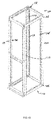
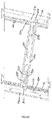
- FIGS. 1A - 2 there is shown a standard server frame 100 that has four corner posts 110 that are secured to a base structure 120 and a top structure 130 by bolts 105.
- the corner posts 110 include standard EIA-310 openings 115 and spacing (shown in greater detail in FIG. 2 ). As illustrated, the corner posts 110 extend vertically and are designed to support servers 140 or other electronic components.
- the standard openings 115 are designed to receive and secure to a standard support rail system.
- the present invention further includes an improvement over the standard server frames. Referring now also to FIG. 1B through FIG.
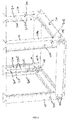
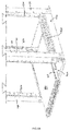
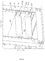
- the standard server frame 100 can now be improved by including an interior post 200 secured directly to each corner post 110 by fasteners 205.
- the fasteners 205 may be similarly defined as bolts 105.
- Each interior post 200 has a base plate 210 and an arm plate 220 extending substantially perpendicularly from the base plate 210 and extending inwardly such that the arm plate 220 is facing a diametrically opposed arm plate 220' on the opposite corner.
- Each interior post 200 may be secured directly to a corner post 110 (either to an end wall 110a or side wall 110b defined thereby) or to the base structure 120 and a top structure 130 (further discussed below).
- a pair of interior posts would be secured either to or adjacent the two back corner posts while a pair of interior posts would be secured against to or adjacent the two front corner post.
- the arm plates on the two interior posts about the back corner posts would face each other while the arm plates on the two interior posts about the front corner posts would face each other.
- a fastening opening 202 on the base plate 210 would align with an opening 112 on the corner post 110 for receipt of the fastener 205.
- rail apertures 225 Positioned along the arm plate 220 are rail apertures 225, which as described below are sized and positioned to receive hooks (427 or 432) extending from an improved outer rail 420.
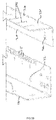
- a support brace 300 can be utilized between a pair of front or back interior posts.
- the support brace 300 spans across a pair of front or back interior posts 200 and help to keep the two interior posts aligned.
- the support brace 300 includes brace ends 305, each brace end 305 have an end slot 310 to receive the arm plate 220 when the support brace 300 is attached.
- the end slot 310 in the brace end 305 creates a brace end member 315 on the distal side of the end slot 310.
- the brace body 320 is positioned on the other side of the end slot 310. Each side of the brace body 320 adjacent the end slot 310 has an extension pin 335, which when the brace is attached, extends into an EIA-310 opening 115 on the corner post 110.
- an end bracket 350 are secured at each brace end 305. The end bracket 350 is secured about each brace end with screws 352.
- each end bracket 350 includes a bracket head 355 that is sized to fit in a rail aperture 225 on the interior post 200.
- the interior posts 200 allow for the quick attachment of outer rails 420, which are part of the sliding rail structure 400.
- the outer rails 400 can be engaged using the combination of a tool-less clip or may use hardware (screws/quick rivets/thumbscrews/etc.) dependent on user preference.
- the outer rails are more universal, meaning they are common between a variety of equipment manufacturers and equipment models.
- prior art tool-less rails employ end mechanism that reduce the amount of volume available to the server chassis by wrapping around the outside of the server frame ends, while the proposed embodiments utilize end mechanism contained on the inside of the server frame to maximize the usable volume.
- the sliding rail structure 400 includes a typically inner rail 410 that is secured and fastened to the equipment.
- the inner rail 410 slides in engagement with the outer rail 420.
- the inner rail 410 attaches to front/back pair of interior posts 200 and once attached on either side of the standard server frame 100, the equipment 140 can slide along the sliding rail structure 400.
- interior posts 200 do not interfere with the standard openings to allow the user to utilize both the interior posts 200 and the corner posts to attached equipment ( FIG. 6B ).
- typical outer rails 218 can be used to clip and attached to the standard openings 115 on the corner post 110, while the improved outer rail 420 can be used to secure equipment to the interior posts 200.
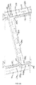
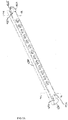
- the outer rail 420 extends from the front to the rear of the server frame 100. Positioned about the rear end 425 of the outer rail 420 are rear facing hooks 427 that are spaced to fit in the rail apertures 225 of the arm plate 220 that is positioned about the rear of the server frame. While the term hooks are used throughout, the hooks may be easily replaced with slotted tabs or regular tabs without changes the scope or intention of the structure. Positioned about the front end 430 of the outer rail 420 are also rear facing hooks 432. Similarly, when attached the rear facing hooks 432 positioned about the front end 430 are spaced to fit in the rail apertures 225 of the arm plate 220 that is positioned about the front of the server frame 100.
- the rear facing hooks 427 and 432 are inserted in rail apertures 225 in interior posts 200 that are positioned at the front and rear of the server frame 100.
- the outer rail 420 can then be slide rearwardly so the rear facing hooks secure against the rail apertures (this is shown in FIG 8 ).
- outer rails 420 are shown attached to the interior posts 200.
- the current standard rails (which consist of an outer rail attached to the corner posts and an inner rail attached to the equipment and which slides with respect to the outer rail when the rails are connected) are often customized based on the equipment or equipment manufacturer.
- a server manufactured by Company A uses different standard rails than a server manufactured by Company B.
- Equipment X made by Company A may also use different standard rails than Equipment Z made by the same company.
- the use of the term standard rails simply refers to the fact that the rails attached to the corner posts uses a standard measured distance between the corner posts and uses a standard set of EIA-310 standard holes.
- the present invention with an interior post that is set back from the standard corner posts EIA-310 holes, widens the distance such that the new outer rails 420 that attach to the interior posts (as opposed to the corner posts) can accommodate equipment larger than standard equipment that fits within the distances defined by the EUA-310 holes.
- the present invention creates a more versatile outer rail that is able to accommodate various inner rails 422. As such, when equipment is changed or moved, while the inner rail has to change, the outer rail once installed can remain fixed.
- the outer rail 420 may include a clip 450 made of a spring steel that allows it to flex.
- the clip 450 is secured against the inside body 440 of the outer rail 420 the clip 450 at one end 475 by a rivet 477 and includes a pair of outwardly facing flanges 452 at the other end 479 that fit into grooves 434 that are adjacent the front end 430 rear facing hooks 432 on the outer rail 420.
- the outwardly facing flanges 452 When attaching the front end 430 of the outer rail 420 to the server frame 100, the outwardly facing flanges 452 flex inwardly to allow the rear facing hooks 432 to slide into engagement with the rail apertures 225. Once positioned ( FIG. 8 ) the outwardly facing flanges 452 return to their normal resting position against an edge 227 of the arm plate 220 of the interior post 200.To unlock and remove the outer rail 420 the outwardly facing flanges 452 are pressed inwardly until the user can slide the outer rail out of engagement with the interior post 200.
- the outer rail 420 includes a clip 450 that is locked in place by an outwardly facing screw 460 such that the outer rail 420 can only be unlocked from the inside of the server frame 100.Once in positioned as described above, the screw 460 is placed to secure the clip 450 and prevent the clip from flexing out of engagement with the interior post. The outwardly facing screw 460 is secured through a clip opening 458 and a corresponding opening in the outer rail 420.
- each interior post 200 may be secured directly to a corner post 110 (either to an end wall 110a or side wall 110b defined thereby) or to the base structure 120 and a top structure 130.
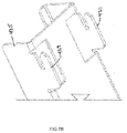
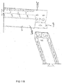
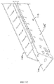
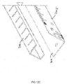
- Figures 11A - 11C illustrate in an alternative embodiment the interior post 200 being part of the corner post 110, to create a new corner post 1100.
- the corner post 1100 includes an end wall 1105 and a side wall 1110.
- the corner post 1100 is attached to the top and bottom structures of the server frame. Extending from the side wall 1110 or the end wall is the interior post 200.
- the interior post 200 extends from an edge of the side wall 1110.
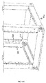
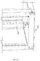
- Figures 12A - 12C illustrate in an alternative embodiment the interior post 200 being secured to the side wall 1210 of the corner post 1200, via fasteners or by welding.
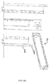
- Figures 13A - 13B the interior post 200 is fastened directly to the top (not shown) and bottom structure 120.
- the side wall 2000 of the interior post includes a flange 2005 with an opening to align with an opening on the bottom structure and to receive a fastener. The same (while not shown) would be provided by the top structure of the service frame.
- the server rack system provides for a more complete rail system that allows servers to be attached to the internal frame such that the rails can be mounted further apart than if the rails are mounted in a standard EIA-310 19" rack.
- This extra width allows the invention to provide for more mounting solutions for a wider variety of server, network and storage chassis types.
- the system is also extremely changeable.
- the simplified rail and frame embodiments provided herein make it is easy to remove and replace rails to accommodate different size chassis.
- clips and hooks may be as configured through the illustrations and descriptions and thus have in one or more embodiments particular meanings.
- clips can be a spring-like material used to help secure the ends of the outer rails to the interior posts.
- various hardware or fasteners may be used without deviating from the spirit and scope of the invention.
- hooks may be a device that extends outwardly and towards the rear from one side of the rail and which are designed to slide within a defined rail aperture.
- the term hooks may encompass broader type fasteners and means of fastening one component to another.
- the hooks 427 and 432 may cover a knob extending outwardly from the rail which slides into a keyhole aperture.
- the aperture and hooks for which are referred to in the claims can accommodate any type of fastening pair that one skilled in the art could easily replace to accomplish the same functionality.
- the embodiments of the present invention utilize terms such as the front and rear. It being well understood that these terms or the orientation can be reversed such that the components or portions positioned at the rear could easily be switched to the front. Such a change in the orientation are well within the scope of the present invention.
Landscapes
- Engineering & Computer Science (AREA)
- Microelectronics & Electronic Packaging (AREA)
- Computer Hardware Design (AREA)
- General Engineering & Computer Science (AREA)
- Drawers Of Furniture (AREA)
- Assembled Shelves (AREA)
Applications Claiming Priority (1)
| Application Number | Priority Date | Filing Date | Title |
|---|---|---|---|
| US14/865,931 US9456520B1 (en) | 2015-09-25 | 2015-09-25 | Server rack system for mounting equipment |
Publications (3)
| Publication Number | Publication Date |
|---|---|
| EP3157315A2 true EP3157315A2 (de) | 2017-04-19 |
| EP3157315A3 EP3157315A3 (de) | 2017-08-02 |
| EP3157315B1 EP3157315B1 (de) | 2019-02-13 |
Family
ID=55952953
Family Applications (1)
| Application Number | Title | Priority Date | Filing Date |
|---|---|---|---|
| EP16166526.0A Not-in-force EP3157315B1 (de) | 2015-09-25 | 2016-04-22 | Serverracksystem für montageausrüstung |
Country Status (4)
| Country | Link |
|---|---|
| US (1) | US9456520B1 (de) |
| EP (1) | EP3157315B1 (de) |
| CN (1) | CN106559965B (de) |
| TW (1) | TWI627891B (de) |
Families Citing this family (9)
| Publication number | Priority date | Publication date | Assignee | Title |
|---|---|---|---|---|
| FI125677B (fi) * | 2013-06-27 | 2016-01-15 | Fibox Oy Ab | Asennuskehys ja -kisko elektroniikka- ja instrumentointikoteloa varten |
| USD846971S1 (en) * | 2015-09-25 | 2019-04-30 | Innovation First, Inc. | Rail for use in a server equipment rack |
| US9814156B2 (en) * | 2015-09-25 | 2017-11-07 | Innovation First, Inc. | Server rack system for mounting equipment |
| US10271451B2 (en) * | 2017-06-30 | 2019-04-23 | Mastercard International Incorporated | Mounting assemblies for supporting card readers in electronic equipment racks, and related methods |
| USD926024S1 (en) * | 2018-04-19 | 2021-07-27 | Goldfinch Brothers Inc. | Sliding door top rail |
| USD914008S1 (en) * | 2019-11-15 | 2021-03-23 | Innovation First, Inc. | Server rack shelf |
| USD914665S1 (en) * | 2019-11-15 | 2021-03-30 | Innovation First, Inc. | Server rack shelf |
| US11576277B2 (en) * | 2020-02-14 | 2023-02-07 | Quanta Computer Inc. | Rack for supporting servers of varying heights |
| JP7680161B2 (ja) * | 2021-10-29 | 2025-05-20 | 日東工業株式会社 | 支持部品の取付構造及び電気機器収納用箱 |
Family Cites Families (42)
| Publication number | Priority date | Publication date | Assignee | Title |
|---|---|---|---|---|
| US5149026A (en) * | 1991-08-28 | 1992-09-22 | Allen Roger D | Wire support apparatus |
| US5546277A (en) * | 1994-05-24 | 1996-08-13 | Sun Microsystems, Inc. | Computer component torsional latching mechanism and method |
| US5535972A (en) * | 1994-12-28 | 1996-07-16 | Fallago; Richard P. | Adapter for adjustable shelving system |
| US5791498A (en) * | 1997-01-21 | 1998-08-11 | Dell U.S.A., L.P. | Rack mount mechanism having an angled bar-nut |
| DE19750427C1 (de) * | 1997-11-14 | 1999-07-08 | Loh Kg Rittal Werk | Befestigungsvorrichtung |
| US6021909A (en) * | 1998-11-13 | 2000-02-08 | Hewlett-Packard Company | Equipment enclosure rack support rail system |
| US6220461B1 (en) * | 1999-07-08 | 2001-04-24 | L.A. Darling Company | Slant shelf system |
| US6681942B2 (en) * | 1999-10-27 | 2004-01-27 | Hewlett-Packard Development Company | Rack mount assembly |
| US7504581B2 (en) * | 2006-03-13 | 2009-03-17 | Panduit Corp. | Network cabinet |
| US6785459B2 (en) * | 2001-06-26 | 2004-08-31 | Adc Telecommunications, Inc. | Cable management brackets and cabinet |
| US6554142B2 (en) * | 2001-07-27 | 2003-04-29 | Dell Products L.P. | Variable mount rack system arm assembly |
| US6702124B2 (en) * | 2001-12-06 | 2004-03-09 | Hewlett-Packard Development Company, L.P. | Flat spring clip for tool-less slide installation |
| US6516955B1 (en) * | 2002-01-17 | 2003-02-11 | Eaton Corporation | Modular cabinet frame |
| US6891727B2 (en) * | 2002-08-21 | 2005-05-10 | International Business Machines Corporation | Apparatus and system to mount a device to a rack |
| US6866154B2 (en) * | 2002-12-03 | 2005-03-15 | Dell Products L.P. | Tool-less attachment bracket |
| US6773080B2 (en) * | 2002-12-06 | 2004-08-10 | King Slide Works, Co., Ltd. | Bracket device for a track assembly |
| TW564012U (en) * | 2003-03-28 | 2003-11-21 | Hon Hai Prec Ind Co Ltd | Mounting assembly for a cabinet |
| US20040189161A1 (en) * | 2003-03-28 | 2004-09-30 | Davis Brooks I. | Zero rack unit space utilization |
| TWM259213U (en) * | 2004-06-28 | 2005-03-11 | Tatung Co | Fixing sheet of sliding rail |
| US7472970B2 (en) * | 2004-11-17 | 2009-01-06 | American Power Conversion Corporation | Equipment enclosure kit and assembly method |
| US7293666B2 (en) * | 2004-11-17 | 2007-11-13 | American Power Conversion Corporation | Equipment enclosure kit and assembly method |
| US7795532B2 (en) * | 2006-03-13 | 2010-09-14 | Panduit Corp. | Network Cabinet |
| TWM308616U (en) * | 2006-10-20 | 2007-03-21 | Inventec Corp | Fixing bracket |
| US7780253B1 (en) * | 2007-01-24 | 2010-08-24 | Gslide Corporation | Sliding rail assembly support frame and server frame mounting arrangement |
| US7764495B2 (en) * | 2007-04-30 | 2010-07-27 | Adc Telecommunications, Inc. | Telecommunication cabinet with airflow ducting |
| US9038973B2 (en) * | 2007-07-12 | 2015-05-26 | Panduit Corp. | Accessory bracket |
| CN101604193B (zh) * | 2008-06-13 | 2012-11-21 | 鸿富锦精密工业(深圳)有限公司 | 滑轨装置 |
| CN101606789B (zh) * | 2008-06-16 | 2012-05-30 | 鸿富锦精密工业(深圳)有限公司 | 滑轨固定装置 |
| US8424694B2 (en) * | 2008-10-03 | 2013-04-23 | Brian Eustace | Reduced weight storage rack |
| US20100200523A1 (en) * | 2009-02-09 | 2010-08-12 | Dell Products L.P. | Tool-less Rack Mounting Apparatus and Systems |
| US8083298B2 (en) * | 2009-03-26 | 2011-12-27 | Dell Products L.P. | Rail kit with universal mounting connection brackets |
| US8262041B2 (en) * | 2009-09-29 | 2012-09-11 | American Power Conversion Corporation | Tool-less installation system and method of U-mounted devices |
| US20120062091A1 (en) * | 2010-09-10 | 2012-03-15 | Donowho D Brian | Vertical mounting rail with cable management features |
| EP2429271A2 (de) * | 2010-09-10 | 2012-03-14 | Chatsworth Products, Inc. | Schienenabdichtung für Gehäuse eines Elektronikgeräts |
| US8787023B2 (en) * | 2010-09-10 | 2014-07-22 | Chatsworth Products, Inc. | Rail mounting clamp for electronic equipment enclosure |
| US8901438B2 (en) * | 2010-09-10 | 2014-12-02 | Chatsworth Products, Inc. | Electronic equipment cabinet structure |
| CN102548323B (zh) * | 2010-12-16 | 2016-03-30 | 鸿富锦精密工业(深圳)有限公司 | 滑轨安装装置 |
| US8901418B2 (en) * | 2012-06-25 | 2014-12-02 | Panduit Corp. | Server cabinet |
| CN203645955U (zh) * | 2013-11-29 | 2014-06-11 | 加弘科技咨询(上海)有限公司 | 可调节的机柜式滑轨 |
| CN104675839B (zh) * | 2013-11-29 | 2017-07-21 | 英业达科技有限公司 | 悬挂结构及具有该悬挂结构的机架 |
| CN104754910A (zh) * | 2013-12-26 | 2015-07-01 | 鸿富锦精密工业(深圳)有限公司 | 滑轨组合 |
| CN204069541U (zh) * | 2014-10-29 | 2014-12-31 | 泛达通讯零部件(无锡)有限公司 | 拼装式机柜 |
-
2015
- 2015-09-25 US US14/865,931 patent/US9456520B1/en active Active
-
2016
- 2016-04-15 TW TW105111803A patent/TWI627891B/zh active
- 2016-04-22 EP EP16166526.0A patent/EP3157315B1/de not_active Not-in-force
- 2016-06-06 CN CN201610394394.2A patent/CN106559965B/zh active Active
Non-Patent Citations (1)
| Title |
|---|
| None |
Also Published As
| Publication number | Publication date |
|---|---|
| TWI627891B (zh) | 2018-06-21 |
| CN106559965A (zh) | 2017-04-05 |
| CN106559965B (zh) | 2019-10-01 |
| EP3157315B1 (de) | 2019-02-13 |
| EP3157315A3 (de) | 2017-08-02 |
| US9456520B1 (en) | 2016-09-27 |
| TW201713191A (zh) | 2017-04-01 |
Similar Documents
| Publication | Publication Date | Title |
|---|---|---|
| US9814156B2 (en) | Server rack system for mounting equipment | |
| US9456520B1 (en) | Server rack system for mounting equipment | |
| US6373707B1 (en) | Module mounting slide clamp mechanism | |
| US7189924B1 (en) | Rack-mount computer cable management arm | |
| US9370119B2 (en) | Sliding rack-mountable rails for rack-mountable components | |
| US9924611B2 (en) | Connectors to secure multiple rails in a server rack | |
| US7762411B2 (en) | Tool-less rack rail system incorporating clamping mechanism | |
| US6739682B2 (en) | Slide rail structure for case cabinets | |
| US20030019824A1 (en) | Variable mount rack system arm assembly | |
| US20030052581A1 (en) | Expandable slide and rail assembly for a rack and method of installing same | |
| US7857267B2 (en) | Unique mounting for computer equipment in frames | |
| US20080303390A1 (en) | Server rack assembly | |
| US20030155471A1 (en) | System and means for the secure mounting of a device bracket | |
| US20030052580A1 (en) | Snap-on slide and rail assembly and method of assembling same | |
| US7920387B2 (en) | Removable card guides for horizontal line cards | |
| EP3716272B1 (de) | Rahmen für festplatten | |
| MX2011013359A (es) | Metodo y aparato para el montaje de componentes de bastidor en bastidores. | |
| US20060283816A1 (en) | Rack-mounted bracket assembly | |
| US6382748B1 (en) | Cabinet system | |
| US6622366B2 (en) | Method for device rack-mounting | |
| US9936601B2 (en) | Cable management assembly for rack mounted equipment | |
| US20070158280A1 (en) | Computer server rack system | |
| CN213640102U (zh) | 一种可调节内部分隔空间的柜体 | |
| US10271451B2 (en) | Mounting assemblies for supporting card readers in electronic equipment racks, and related methods | |
| EP2937017B1 (de) | Montagevorrichtung für ein Schubladensystem |
Legal Events
| Date | Code | Title | Description |
|---|---|---|---|
| PUAI | Public reference made under article 153(3) epc to a published international application that has entered the european phase |
Free format text: ORIGINAL CODE: 0009012 |
|
| STAA | Information on the status of an ep patent application or granted ep patent |
Free format text: STATUS: THE APPLICATION HAS BEEN PUBLISHED |
|
| AK | Designated contracting states |
Kind code of ref document: A2 Designated state(s): AL AT BE BG CH CY CZ DE DK EE ES FI FR GB GR HR HU IE IS IT LI LT LU LV MC MK MT NL NO PL PT RO RS SE SI SK SM TR |
|
| AX | Request for extension of the european patent |
Extension state: BA ME |
|
| PUAL | Search report despatched |
Free format text: ORIGINAL CODE: 0009013 |
|
| AK | Designated contracting states |
Kind code of ref document: A3 Designated state(s): AL AT BE BG CH CY CZ DE DK EE ES FI FR GB GR HR HU IE IS IT LI LT LU LV MC MK MT NL NO PL PT RO RS SE SI SK SM TR |
|
| AX | Request for extension of the european patent |
Extension state: BA ME |
|
| RIC1 | Information provided on ipc code assigned before grant |
Ipc: H05K 7/14 20060101AFI20170626BHEP |
|
| STAA | Information on the status of an ep patent application or granted ep patent |
Free format text: STATUS: REQUEST FOR EXAMINATION WAS MADE |
|
| 17P | Request for examination filed |
Effective date: 20180201 |
|
| RBV | Designated contracting states (corrected) |
Designated state(s): AL AT BE BG CH CY CZ DE DK EE ES FI FR GB GR HR HU IE IS IT LI LT LU LV MC MK MT NL NO PL PT RO RS SE SI SK SM TR |
|
| GRAP | Despatch of communication of intention to grant a patent |
Free format text: ORIGINAL CODE: EPIDOSNIGR1 |
|
| STAA | Information on the status of an ep patent application or granted ep patent |
Free format text: STATUS: GRANT OF PATENT IS INTENDED |
|
| INTG | Intention to grant announced |
Effective date: 20181109 |
|
| GRAS | Grant fee paid |
Free format text: ORIGINAL CODE: EPIDOSNIGR3 |
|
| GRAA | (expected) grant |
Free format text: ORIGINAL CODE: 0009210 |
|
| STAA | Information on the status of an ep patent application or granted ep patent |
Free format text: STATUS: THE PATENT HAS BEEN GRANTED |
|
| AK | Designated contracting states |
Kind code of ref document: B1 Designated state(s): AL AT BE BG CH CY CZ DE DK EE ES FI FR GB GR HR HU IE IS IT LI LT LU LV MC MK MT NL NO PL PT RO RS SE SI SK SM TR |
|
| REG | Reference to a national code |
Ref country code: GB Ref legal event code: FG4D |
|
| REG | Reference to a national code |
Ref country code: CH Ref legal event code: EP Ref country code: AT Ref legal event code: REF Ref document number: 1096992 Country of ref document: AT Kind code of ref document: T Effective date: 20190215 |
|
| REG | Reference to a national code |
Ref country code: IE Ref legal event code: FG4D |
|
| REG | Reference to a national code |
Ref country code: DE Ref legal event code: R096 Ref document number: 602016009878 Country of ref document: DE |
|
| REG | Reference to a national code |
Ref country code: LT Ref legal event code: MG4D |
|
| REG | Reference to a national code |
Ref country code: NL Ref legal event code: MP Effective date: 20190213 |
|
| PG25 | Lapsed in a contracting state [announced via postgrant information from national office to epo] |
Ref country code: FI Free format text: LAPSE BECAUSE OF FAILURE TO SUBMIT A TRANSLATION OF THE DESCRIPTION OR TO PAY THE FEE WITHIN THE PRESCRIBED TIME-LIMIT Effective date: 20190213 Ref country code: NO Free format text: LAPSE BECAUSE OF FAILURE TO SUBMIT A TRANSLATION OF THE DESCRIPTION OR TO PAY THE FEE WITHIN THE PRESCRIBED TIME-LIMIT Effective date: 20190513 Ref country code: LT Free format text: LAPSE BECAUSE OF FAILURE TO SUBMIT A TRANSLATION OF THE DESCRIPTION OR TO PAY THE FEE WITHIN THE PRESCRIBED TIME-LIMIT Effective date: 20190213 Ref country code: SE Free format text: LAPSE BECAUSE OF FAILURE TO SUBMIT A TRANSLATION OF THE DESCRIPTION OR TO PAY THE FEE WITHIN THE PRESCRIBED TIME-LIMIT Effective date: 20190213 Ref country code: PT Free format text: LAPSE BECAUSE OF FAILURE TO SUBMIT A TRANSLATION OF THE DESCRIPTION OR TO PAY THE FEE WITHIN THE PRESCRIBED TIME-LIMIT Effective date: 20190613 Ref country code: NL Free format text: LAPSE BECAUSE OF FAILURE TO SUBMIT A TRANSLATION OF THE DESCRIPTION OR TO PAY THE FEE WITHIN THE PRESCRIBED TIME-LIMIT Effective date: 20190213 |
|
| PG25 | Lapsed in a contracting state [announced via postgrant information from national office to epo] |
Ref country code: RS Free format text: LAPSE BECAUSE OF FAILURE TO SUBMIT A TRANSLATION OF THE DESCRIPTION OR TO PAY THE FEE WITHIN THE PRESCRIBED TIME-LIMIT Effective date: 20190213 Ref country code: LV Free format text: LAPSE BECAUSE OF FAILURE TO SUBMIT A TRANSLATION OF THE DESCRIPTION OR TO PAY THE FEE WITHIN THE PRESCRIBED TIME-LIMIT Effective date: 20190213 Ref country code: BG Free format text: LAPSE BECAUSE OF FAILURE TO SUBMIT A TRANSLATION OF THE DESCRIPTION OR TO PAY THE FEE WITHIN THE PRESCRIBED TIME-LIMIT Effective date: 20190513 Ref country code: IS Free format text: LAPSE BECAUSE OF FAILURE TO SUBMIT A TRANSLATION OF THE DESCRIPTION OR TO PAY THE FEE WITHIN THE PRESCRIBED TIME-LIMIT Effective date: 20190613 Ref country code: GR Free format text: LAPSE BECAUSE OF FAILURE TO SUBMIT A TRANSLATION OF THE DESCRIPTION OR TO PAY THE FEE WITHIN THE PRESCRIBED TIME-LIMIT Effective date: 20190514 Ref country code: HR Free format text: LAPSE BECAUSE OF FAILURE TO SUBMIT A TRANSLATION OF THE DESCRIPTION OR TO PAY THE FEE WITHIN THE PRESCRIBED TIME-LIMIT Effective date: 20190213 |
|
| REG | Reference to a national code |
Ref country code: AT Ref legal event code: MK05 Ref document number: 1096992 Country of ref document: AT Kind code of ref document: T Effective date: 20190213 |
|
| PG25 | Lapsed in a contracting state [announced via postgrant information from national office to epo] |
Ref country code: EE Free format text: LAPSE BECAUSE OF FAILURE TO SUBMIT A TRANSLATION OF THE DESCRIPTION OR TO PAY THE FEE WITHIN THE PRESCRIBED TIME-LIMIT Effective date: 20190213 Ref country code: DK Free format text: LAPSE BECAUSE OF FAILURE TO SUBMIT A TRANSLATION OF THE DESCRIPTION OR TO PAY THE FEE WITHIN THE PRESCRIBED TIME-LIMIT Effective date: 20190213 Ref country code: SK Free format text: LAPSE BECAUSE OF FAILURE TO SUBMIT A TRANSLATION OF THE DESCRIPTION OR TO PAY THE FEE WITHIN THE PRESCRIBED TIME-LIMIT Effective date: 20190213 Ref country code: AL Free format text: LAPSE BECAUSE OF FAILURE TO SUBMIT A TRANSLATION OF THE DESCRIPTION OR TO PAY THE FEE WITHIN THE PRESCRIBED TIME-LIMIT Effective date: 20190213 Ref country code: IT Free format text: LAPSE BECAUSE OF FAILURE TO SUBMIT A TRANSLATION OF THE DESCRIPTION OR TO PAY THE FEE WITHIN THE PRESCRIBED TIME-LIMIT Effective date: 20190213 Ref country code: ES Free format text: LAPSE BECAUSE OF FAILURE TO SUBMIT A TRANSLATION OF THE DESCRIPTION OR TO PAY THE FEE WITHIN THE PRESCRIBED TIME-LIMIT Effective date: 20190213 Ref country code: RO Free format text: LAPSE BECAUSE OF FAILURE TO SUBMIT A TRANSLATION OF THE DESCRIPTION OR TO PAY THE FEE WITHIN THE PRESCRIBED TIME-LIMIT Effective date: 20190213 Ref country code: CZ Free format text: LAPSE BECAUSE OF FAILURE TO SUBMIT A TRANSLATION OF THE DESCRIPTION OR TO PAY THE FEE WITHIN THE PRESCRIBED TIME-LIMIT Effective date: 20190213 |
|
| REG | Reference to a national code |
Ref country code: DE Ref legal event code: R119 Ref document number: 602016009878 Country of ref document: DE |
|
| PG25 | Lapsed in a contracting state [announced via postgrant information from national office to epo] |
Ref country code: SM Free format text: LAPSE BECAUSE OF FAILURE TO SUBMIT A TRANSLATION OF THE DESCRIPTION OR TO PAY THE FEE WITHIN THE PRESCRIBED TIME-LIMIT Effective date: 20190213 Ref country code: PL Free format text: LAPSE BECAUSE OF FAILURE TO SUBMIT A TRANSLATION OF THE DESCRIPTION OR TO PAY THE FEE WITHIN THE PRESCRIBED TIME-LIMIT Effective date: 20190213 |
|
| REG | Reference to a national code |
Ref country code: CH Ref legal event code: PL |
|
| REG | Reference to a national code |
Ref country code: BE Ref legal event code: MM Effective date: 20190430 |
|
| PLBE | No opposition filed within time limit |
Free format text: ORIGINAL CODE: 0009261 |
|
| STAA | Information on the status of an ep patent application or granted ep patent |
Free format text: STATUS: NO OPPOSITION FILED WITHIN TIME LIMIT |
|
| PG25 | Lapsed in a contracting state [announced via postgrant information from national office to epo] |
Ref country code: AT Free format text: LAPSE BECAUSE OF FAILURE TO SUBMIT A TRANSLATION OF THE DESCRIPTION OR TO PAY THE FEE WITHIN THE PRESCRIBED TIME-LIMIT Effective date: 20190213 Ref country code: MC Free format text: LAPSE BECAUSE OF FAILURE TO SUBMIT A TRANSLATION OF THE DESCRIPTION OR TO PAY THE FEE WITHIN THE PRESCRIBED TIME-LIMIT Effective date: 20190213 Ref country code: LU Free format text: LAPSE BECAUSE OF NON-PAYMENT OF DUE FEES Effective date: 20190422 |
|
| 26N | No opposition filed |
Effective date: 20191114 |
|
| PG25 | Lapsed in a contracting state [announced via postgrant information from national office to epo] |
Ref country code: DE Free format text: LAPSE BECAUSE OF NON-PAYMENT OF DUE FEES Effective date: 20191101 Ref country code: LI Free format text: LAPSE BECAUSE OF NON-PAYMENT OF DUE FEES Effective date: 20190430 Ref country code: CH Free format text: LAPSE BECAUSE OF NON-PAYMENT OF DUE FEES Effective date: 20190430 |
|
| PG25 | Lapsed in a contracting state [announced via postgrant information from national office to epo] |
Ref country code: FR Free format text: LAPSE BECAUSE OF NON-PAYMENT OF DUE FEES Effective date: 20190430 Ref country code: BE Free format text: LAPSE BECAUSE OF NON-PAYMENT OF DUE FEES Effective date: 20190430 Ref country code: SI Free format text: LAPSE BECAUSE OF FAILURE TO SUBMIT A TRANSLATION OF THE DESCRIPTION OR TO PAY THE FEE WITHIN THE PRESCRIBED TIME-LIMIT Effective date: 20190213 |
|
| PG25 | Lapsed in a contracting state [announced via postgrant information from national office to epo] |
Ref country code: TR Free format text: LAPSE BECAUSE OF FAILURE TO SUBMIT A TRANSLATION OF THE DESCRIPTION OR TO PAY THE FEE WITHIN THE PRESCRIBED TIME-LIMIT Effective date: 20190213 |
|
| PG25 | Lapsed in a contracting state [announced via postgrant information from national office to epo] |
Ref country code: IE Free format text: LAPSE BECAUSE OF NON-PAYMENT OF DUE FEES Effective date: 20190422 |
|
| GBPC | Gb: european patent ceased through non-payment of renewal fee |
Effective date: 20200422 |
|
| PG25 | Lapsed in a contracting state [announced via postgrant information from national office to epo] |
Ref country code: GB Free format text: LAPSE BECAUSE OF NON-PAYMENT OF DUE FEES Effective date: 20200422 |
|
| PG25 | Lapsed in a contracting state [announced via postgrant information from national office to epo] |
Ref country code: CY Free format text: LAPSE BECAUSE OF FAILURE TO SUBMIT A TRANSLATION OF THE DESCRIPTION OR TO PAY THE FEE WITHIN THE PRESCRIBED TIME-LIMIT Effective date: 20190213 |
|
| PG25 | Lapsed in a contracting state [announced via postgrant information from national office to epo] |
Ref country code: MT Free format text: LAPSE BECAUSE OF FAILURE TO SUBMIT A TRANSLATION OF THE DESCRIPTION OR TO PAY THE FEE WITHIN THE PRESCRIBED TIME-LIMIT Effective date: 20190213 Ref country code: HU Free format text: LAPSE BECAUSE OF FAILURE TO SUBMIT A TRANSLATION OF THE DESCRIPTION OR TO PAY THE FEE WITHIN THE PRESCRIBED TIME-LIMIT; INVALID AB INITIO Effective date: 20160422 |
|
| PG25 | Lapsed in a contracting state [announced via postgrant information from national office to epo] |
Ref country code: MK Free format text: LAPSE BECAUSE OF FAILURE TO SUBMIT A TRANSLATION OF THE DESCRIPTION OR TO PAY THE FEE WITHIN THE PRESCRIBED TIME-LIMIT Effective date: 20190213 |