EP3157372B1 - Bracelet de montre réglable - Google Patents
Bracelet de montre réglable Download PDFInfo
- Publication number
- EP3157372B1 EP3157372B1 EP15811520.4A EP15811520A EP3157372B1 EP 3157372 B1 EP3157372 B1 EP 3157372B1 EP 15811520 A EP15811520 A EP 15811520A EP 3157372 B1 EP3157372 B1 EP 3157372B1
- Authority
- EP
- European Patent Office
- Prior art keywords
- micro
- adjustment member
- buckle
- adjustment
- strap
- Prior art date
- Legal status (The legal status is an assumption and is not a legal conclusion. Google has not performed a legal analysis and makes no representation as to the accuracy of the status listed.)
- Active
Links
- 230000000994 depressogenic effect Effects 0.000 claims description 3
- 230000000881 depressing effect Effects 0.000 claims 1
- 210000000707 wrist Anatomy 0.000 description 14
- 229910052755 nonmetal Inorganic materials 0.000 description 8
- 230000007246 mechanism Effects 0.000 description 5
- 239000002184 metal Substances 0.000 description 4
- 230000008859 change Effects 0.000 description 3
- 230000007613 environmental effect Effects 0.000 description 2
- 230000036541 health Effects 0.000 description 2
- 239000000463 material Substances 0.000 description 2
- 230000004048 modification Effects 0.000 description 2
- 238000012986 modification Methods 0.000 description 2
- 230000003247 decreasing effect Effects 0.000 description 1
- 239000010985 leather Substances 0.000 description 1
- 238000004519 manufacturing process Methods 0.000 description 1
- 239000007769 metal material Substances 0.000 description 1
- 150000002843 nonmetals Chemical class 0.000 description 1
Images



Classifications
-
- A—HUMAN NECESSITIES
- A44—HABERDASHERY; JEWELLERY
- A44C—PERSONAL ADORNMENTS, e.g. JEWELLERY; COINS
- A44C5/00—Bracelets; Wrist-watch straps; Fastenings for bracelets or wrist-watch straps
- A44C5/18—Fasteners for straps, chains or the like
- A44C5/22—Fasteners for straps, chains or the like for closed straps
- A44C5/24—Fasteners for straps, chains or the like for closed straps with folding devices
- A44C5/246—Fasteners for straps, chains or the like for closed straps with folding devices having size adjusting means
-
- A—HUMAN NECESSITIES
- A44—HABERDASHERY; JEWELLERY
- A44B—BUTTONS, PINS, BUCKLES, SLIDE FASTENERS, OR THE LIKE
- A44B11/00—Buckles; Similar fasteners for interconnecting straps or the like, e.g. for safety belts
- A44B11/20—Buckles; Similar fasteners for interconnecting straps or the like, e.g. for safety belts engaging holes or the like in strap
- A44B11/24—Buckle with movable prong
-
- Y—GENERAL TAGGING OF NEW TECHNOLOGICAL DEVELOPMENTS; GENERAL TAGGING OF CROSS-SECTIONAL TECHNOLOGIES SPANNING OVER SEVERAL SECTIONS OF THE IPC; TECHNICAL SUBJECTS COVERED BY FORMER USPC CROSS-REFERENCE ART COLLECTIONS [XRACs] AND DIGESTS
- Y10—TECHNICAL SUBJECTS COVERED BY FORMER USPC
- Y10T—TECHNICAL SUBJECTS COVERED BY FORMER US CLASSIFICATION
- Y10T24/00—Buckles, buttons, clasps, etc.
- Y10T24/21—Strap tighteners
- Y10T24/2143—Strap-attached folding lever
- Y10T24/2155—Jewelry-watch straps
-
- Y—GENERAL TAGGING OF NEW TECHNOLOGICAL DEVELOPMENTS; GENERAL TAGGING OF CROSS-SECTIONAL TECHNOLOGIES SPANNING OVER SEVERAL SECTIONS OF THE IPC; TECHNICAL SUBJECTS COVERED BY FORMER USPC CROSS-REFERENCE ART COLLECTIONS [XRACs] AND DIGESTS
- Y10—TECHNICAL SUBJECTS COVERED BY FORMER USPC
- Y10T—TECHNICAL SUBJECTS COVERED BY FORMER US CLASSIFICATION
- Y10T24/00—Buckles, buttons, clasps, etc.
- Y10T24/47—Strap-end-attaching devices
- Y10T24/4782—Watch strap
Definitions
- the present principles generally relates to adjustable watch straps, more particularly, it relates to an adjustable watch strap having the capability of providing micro adjustments between standard adjustments.
- Watches are popular accessories that traditionally provide the time of day and may provide additional data such as the date, a stop watch, etc.
- a watch strap which supports the watch preferably fits snugly enough on a user's wrist to resist rotation due to normal hand movements but without the strap being overly tight so as to provide excessive pressure and discomfort to the user.
- JP2005270248 discloses an adjustment system for an adjustable watch strap.
- Metal watch straps and non-metal watch straps are the two main types of watch straps known in the art.
- the non-metal watch straps may be fabricated out of materials such as leather, plastic or a variety of other materials.
- the adjustment of metal watch straps is accomplished by adding or removing links to the bracelet portion in order to change the circumferential length of the bracelet.
- the straps typically have a fixed length and the circumferential length that the straps encircle the user's wrist is adjusted by securing the strap to a buckle at different holes on the strap.
- Tang buckles and deployment buckles are two main types of buckles that are used on non-metal straps in order to connect the straps and secure them on the user's wrist.
- Tang buckles secure the circumferential length of the strap by including a hook on the buckle which extends into a hole on a strap portion similar to the operation of a traditional belt.
- Deployment buckles for non-metal straps may also include a buckle head having a hook for extending through holes on a strap portion.
- deployment buckles also contain a plurality of metal strips which when opened, enlarge the circumference of the bracelet and allow for easy removal of the watch.
- the deployment buckle also protects the watch from being accidentally dropped upon removal because the straps remain connected to the buckle when the buckle is deployed.
- a disadvantage of traditional deployment buckles is that the deployment buckle cannot be adjusted easily on the user's wrist once it is secured thereon.
- the watch In order to adjust the circumferential length of the strap, the watch must be removed and the buckle must be fastened onto another hole on the strap.
- the holes on traditional straps are spaced far apart and a user may not be able to obtain a proper fit with the provided holes.
- the watch strap may initially not fit well with the provided holes on the watch strap.
- a watch strap that is initially fitted well on the user's wrist may become too loose or too tight based on environmental conditions or health conditions which affect the width of the user's wrist.
- a user may have to add intermediary holes between two existing holes on the watch strap which is a difficult task and diminishes the attractiveness and structural integrity of the watch strap.
- Watch straps have been made with numerous adjustment mechanisms in order to change the circumferential length of the strap around the user's wrist.
- all adjustable straps have adjustment increments, such as the standard spacing for the holes on a strap, which are unable to provide small or micro changes in the circumferential length of the strap between the provided hole adjustments in the band in order to provide an optimal fit for the user.
- Non-metal watch straps normally are adjustable by changing the hole that the strap is affixed to the buckle.
- the circumferential length of the watch strap cannot be adjusted solely at the buckle without changing the hole that the watch strap is secured to the buckle.
- Yet a further aspect of the invention is an adjustable buckle mechanism that is configured to be incorporated into an existing buckle of a watch strap in order to allow the watch strap to be adjustable at the buckle in small or micro increments without changing the hole that the strap is affixed to the buckle.
- the present principles include a micro adjustment system for an adjustable watch strap having first and second strap portions and standard adjustment increments.
- the micro adjustment system features a buckle attached to the first strap portion.
- the buckle includes a receiving slot on a first end and a spring.
- a micro-adjustment member is attached to the second strap portion.
- the micro-adjustment member is configured to be slidably received within or retracted from the receiving slot of the buckle.
- the buckle includes releasable locking means fixedly securing a position of the micro-adjustment member within said receiving slot in one of a plurality of micro increments.
- the micro increments are smaller than the standard adjustment increments.
- the adjustable watch strap of the present principles provides for micro adjustments between the standard watch strap adjustments to its circumferential length at the buckle, in order to provide a precise fit on the user's wrist.
- the adjustable watch strap is able to be easily adjusted by the user without requiring any special tools or skill.
- the adjustable watch strap allows the user to adjust the buckle in order to shorten or increase the circumferential length of the strap without changing the hole that the strap is affixed to the buckle. This provides for an optimal fit when the proper size for the user's wrist falls between two standard adjustment holes that the strap is affixed to the hook of the buckle.
- the spacing and number of apertures on the adjustment mechanism are dimensioned to provide specifically desired micro increments of adjustment between the ordinary adjustment increments, resulting in corresponding micro changes to the circumferential length of the watch strap.
- an adjustable watch strap having the capability of providing micro adjustments to the circumferential length of the watch strap which includes a buckle 2 having a buckle head 11 including a hook 36 which is attached to one of a plurality of holes on a first strap 32, a sliding adjustment member 10 attached to a second strap 34 and a watch case (not shown) which houses the watch element and is attached to the first and second straps.
- the watch strap is preferably fabricated out of a non-metal material.
- the buckle 2, first and second straps 32, 34 and the watch case housing the watch element form a watch assembly which encircles the wrist of the user.
- the sliding adjustment member 10 is configured to be slidably received within or retracted from a slot 6 on the buckle 2.
- the sliding adjustment member is configured to be secured in a plurality of predetermined positions that are configured to provide micro adjustments to the length that the watch assembly encircles the user's wrist without changing the hole that the strap is affixed to the hook 36 of the buckle.
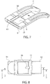
- Fig. 1 shows the buckle 2 and sliding adjustment member 10 in accordance with the present principles.
- the buckle is a deployment buckle which includes a first strip 7 and a second strip 9 that are pivotably connected to each other at a hinge 26.
- the second strip 9 of the buckle shown in the Figs. 1 , 3 , 4 , 5 and 8-10 includes a buckle head 11 at its terminal end.
- the buckle head 11 is configured for releasably receiving the first strap 32 such as by a hook 36 which is received into one of a plurality of holes on the strap.
- the second strip 9 may be pivoted to be positioned on top of the first strip 7 and may have securement means to maintain the buckle in this position.
- the first strip 7 of the buckle has a first end 4 having a receiving slot 6 on a perpendicular wall at its terminal portion of the first end 4.
- the top of the first end 4 is generally U-shaped and includes a narrow bar 13 at the terminal portion, side portions 25 and an opening 8 in the middle portion.
- the opening 8 in the middle portion is defined by the bar 13 at the terminal portion of the first end, the side portions 25 and a wall 30 on a lower surface of the first strip 7 which opposes the bar 13.
- the sliding adjustment member 10 includes a pair of laterally spaced arms 12 on a first end 14 and strap connecting means 16 on a second end 35.
- the strap connecting means 16 comprises a spring bar 38 that is received by two lugs 15 on opposed sides of the second end 35 of the sliding adjustment member.
- the strap connecting means of the sliding adjustment member 10 can be any other connection means known in the art.
- the laterally spaced arms 12 have relatively planar top surfaces 17 and a bottom surface 19 which includes a plurality of spaced teeth 20 extending downwardly and forming apertures 18 between the teeth 20.
- the first strip 7 of the buckle includes a spring 22 having a proximal end 39 which features an integral raised member or button 24 which is positioned adjacent the bar 13 at the top of the terminal portion of the first end 4 of the first strip 7.
- the spring 22 is arranged in the middle portion of the first strip 7 and follows the contours of the first strip.
- the distal end 21 of the spring terminates past the hinge 26 between the first and second strips 7, 9 and the middle longitudinal region of the spring is secured to the first strip by a screw 23 or other releasable or permanent fastening means known in the art.
- the distal end 21 of the spring is preferably free so that it does not restrict movement of the first and second strips 7, 9 of the buckle.
- the spring 22 includes raised side projections 28 on each side. While Fig. 2 shows two raised side projections 28, in other embodiments only a single side projection 28 may be used and still fall within the principles of the invention.
- the raised side projections 28 of the spring are dimensioned to fit within the apertures 18 of the sliding adjustment member in order to lock the position of the adjustment member 10 relative to the first strip 7 of the buckle.
- the user can easily adjust the position of the sliding adjustment member 10 relative to the buckle 2 by pressing the button 24 with a finger or by other means in order to lower the spring and move the raised side projections 28 out of an aperture 18 on the adjustment member arms.
- the arms 12 of the sliding adjustment member may be slid into the slot 6 in order to shorten the circumferential length of the watch assembly at the buckle or they may be retracted from the slot in order to increase the circumferential length of the watch at the buckle.
- the button 24 when the button 24 is released, the raised side projections 28 of the spring are biased upwards by the spring 22 and are received into an aperture 18 on the arms of the sliding adjustment member 10 in order to secure the position of the adjustment member.
- the width of the raised side projections 28 are approximately the same as the width of the aperture.
- the width of the raised side projections may be narrower than the apertures so that there is a degree of play when the sliding adjustment member is in a locked position.
- the top of the raised side projections 28 are angled downwardly toward the terminal portion of the first end.
- different configurations of the raised side projections may be used and still fall within the principles of the invention.
- the spacing and number of apertures on the sliding adjustment member may be dimensioned to provide specific small or micro increments of adjustment and provide specific changes to the circumferential length of the watch strap.
- the micro adjustment increments are smaller than standard adjustment lengths in order to provide an optimal fit for the user.
- the slidable adjustment member may be slid into at least three different positions in order to change the circumferential length of the watch strap.
- the adjustable buckle allows the user to easily adjust the watch at the buckle 2 in micro increments without adjusting the hole that the first strap 32 is affixed to the hook 36 of the buckle head 11 in order to provide an optimal fit for the user's wrist.
- the adjustable buckle provides the user with an optimal fit even when the width of the user's wrist is in between the sizes of two adjacent holes on the first strap portion 32.
- the micro-adjustments of the buckle allow quick and efficient adjustments to be made to the circumferential length of the watch strap in order to compensate for daily wrist size fluctuations due to environmental conditions, health conditions, etc.
- the micro-adjustments of the buckle also allow the circumferential length of the watch strap to be increased to a size greater than the largest standard adjustment size or decreased to a size that is less than the smallest standard adjustment size.
- the sliding adjustment member 10 is fully retracted from the slot 6 on the buckle.
- the sliding adjustment member 10 is fully received within the slot 6 on the buckle.
- the length of the sliding adjustment member arms 12 may also be dimensioned to provide a specific overall possible length of adjustment as may be desired.
- a second bar 31 limits the distance that the sliding adjustment member 10 can be retracted as the button 24 will contact the second bar 31 and prevent further retraction.
- the sliding adjustment member 10 has a portion of its body which has a length and/or width that is greater than the corresponding dimension of the slot 6.
- this portion of the adjustment body comprises a bar 42 on the sliding adjustment member immediately adjacent the arms which has a greater length and width than the slot. Therefore, the portion of the sliding adjustment member body having a greater length and/or width than the slot contacts the bar 13 at the terminal portion of the first end 4 of the first strip and serves to restrict further receiving of the second end of the sliding adjustment member 10 into the receiving slot 6.
- While a deployable or deployment buckle configuration is specifically shown in the figures which uses non-metal strap portions, other strap configurations may be utilized, such as metal bracelet straps having connected first and second straps, or other straps known in the art, and still fall within the principles of the present invention.
- the adjustable buckle may also be configured to be incorporated into a conventional tang buckle or other conventional buckles in order to provide the improved adjustment capabilities of the present invention.
- connection means for attaching the buckle to the straps may be, for example, spring bars that are received by two lugs, or may be any other connection elements known in the art and are not limited to those specifically shown in the figures.
Landscapes
- Buckles (AREA)
Claims (12)
- Système de microréglage destiné à un bracelet de montre réglable présentant des première et seconde parties de bracelet (32, 34) et des incréments de réglage standard, le système de microréglage comprenant :une boucle (2) fixée à la première partie de bracelet, ladite boucle comprenant un emplacement de réception d'une première extrémité et un ressort (22) ;un élément de microréglage (10) fixé sur la seconde partie de bracelet ;dans lequel ledit élément de microréglage est conçu pour être reçu de manière coulissante à l'intérieur ou rétracté de l'emplacement de réception (6) de la boucle ; etladite boucle comprenant en outre un moyen de verrouillage libérable fixant à demeure une position de l'élément de microréglage à l'intérieur dudit emplacement de réception dans un parmi une pluralité de micro-incréments, lesdits micro-incréments étant plus petits que les incréments de réglage standard.
- Système de microréglage selon la revendication 1, dans lequel ledit moyen de verrouillage libérable comprend ;
au moins une saillie surélevée (28) sur ledit ressort (22) dimensionnée pour s'adapter à l'intérieur d'une pluralité d'ouvertures (18) sur l'élément de microréglage ;
dans lequel une position sécurisée de l'élément de microréglage (10) est libérée en appuyant sur le ressort pour libérer ladite au moins une saillie surélevée d'un première ouverture et, après la modification de la position de l'élément de réglage à l'intérieur de l'emplacement de réception (6), la position de l'élément de microréglage est fixée solidement par la libération du ressort, de sorte qu'au moins ladite au moins une saillie surélevée est sollicitée vers le haut dans une seconde ouverture par le ressort. - Système de microréglage selon la revendication 1, dans lequel ledit élément de microréglage (10) comprend une paire de bras espacés latéralement (12) sur une première extrémité et un moyen de raccordement de bracelet (16) sur une seconde extrémité, lesdits bras espacés latéralement étant dimensionnés pour être reçus à l'intérieur de l'emplacement de réception (6) de la boucle.
- Système de microréglage selon la revendication 3, dans lequel les bras espacés latéralement (12) comprennent des surfaces supérieures relativement planes (17) et une surface inférieure (19) présentant une pluralité de dents espacées (20) s'étendant vers le bas formant des ouvertures entre les dents.
- Système de microréglage selon la revendication 2, dans lequel le ressort (22) comprend un bouton surélevé (24) conçu pour libérer la position sécurisée de l'élément de microréglage lorsqu'il est enfoncé.
- Système de microréglage selon la revendication 5, dans lequel le bouton surélevé (24) est positionné à proximité de la première extrémité de la boucle.
- Système de microréglage selon la revendication 3, dans lequel :le ressort comprend un bouton surélevé (24) conçu pour libérer une position sécurisée de l'élément de microréglage (10) quand le bouton est enfoncé ; etl'élément de microréglage comprend une barre (31) fixée solidement sur la partie distale des bras espacés latéralement qui entre en contact avec le bouton du ressort, lorsque l'élément de microréglage est rétracté dans une première longueur afin de limiter la distance à laquelle l'élément de microréglage peut être rétracté.
- Système de microréglage selon la revendication 1, dans lequel l'élément de microréglage (10) présente une première partie (42) présentant une ou plusieurs dimensions qui sont supérieures aux dimensions de l'emplacement (6) de manière à ce que la première partie restreigne en outre la réception de l'élément de microréglage dans l'emplacement.
- Système de microréglage selon la revendication 8, dans lequel la première partie de l'élément de microréglage comprend une barre (42) immédiatement adjacente aux bras (12) de l'élément de microréglage.
- Système de microréglage selon la revendication 2, dans lequel l'élément de microréglage (10) comprend en outre au moins trois ouvertures (18) pour fournir au moins trois réglages différents par micro-incrément possibles du bracelet de montre réglable.
- Système de microréglage selon la revendication 1, dans lequel la boucle (2) comprend en outre des premier et second éléments de bande (7, 9) qui sont raccordés l'un à l'autre de manière pivotante.
- Système de microréglage selon la revendication 11 dans lequel l'emplacement de réception (6) est positionné à proximité de la première bande (7) de la boucle.
Applications Claiming Priority (2)
| Application Number | Priority Date | Filing Date | Title |
|---|---|---|---|
| US14/312,161 US9560900B2 (en) | 2014-06-23 | 2014-06-23 | Adjustable watch strap |
| PCT/US2015/037197 WO2015200332A1 (fr) | 2014-06-23 | 2015-06-23 | Bracelet de montre réglable |
Publications (3)
| Publication Number | Publication Date |
|---|---|
| EP3157372A1 EP3157372A1 (fr) | 2017-04-26 |
| EP3157372A4 EP3157372A4 (fr) | 2018-02-07 |
| EP3157372B1 true EP3157372B1 (fr) | 2019-05-08 |
Family
ID=54868470
Family Applications (1)
| Application Number | Title | Priority Date | Filing Date |
|---|---|---|---|
| EP15811520.4A Active EP3157372B1 (fr) | 2014-06-23 | 2015-06-23 | Bracelet de montre réglable |
Country Status (3)
| Country | Link |
|---|---|
| US (1) | US9560900B2 (fr) |
| EP (1) | EP3157372B1 (fr) |
| WO (1) | WO2015200332A1 (fr) |
Families Citing this family (9)
| Publication number | Priority date | Publication date | Assignee | Title |
|---|---|---|---|---|
| US10463141B2 (en) * | 2014-07-01 | 2019-11-05 | Heloisa Fitzgerald Jewelry | Wearable modular electronic device, such as to hold a selectable and/or replaceable biometric sensor in close proximity to and/or in physical contact with a wearer and/or to hold a battery |
| WO2018188112A1 (fr) * | 2017-04-14 | 2018-10-18 | 华为技术有限公司 | Boucle de bracelet de montre double pouvant réaliser un réglage précis de longueur de bracelet de montre |
| EP3412168B1 (fr) * | 2017-06-07 | 2020-03-25 | Omega SA | Fermoir pour bracelet |
| EP3417734B1 (fr) * | 2017-06-21 | 2021-04-28 | Dexel S.A. | Fermoir pour bracelet comportant un dispositif de réglage de longueur du bracelet |
| EP4164448B1 (fr) | 2020-06-16 | 2025-01-01 | ELC Management LLC | Bracelet de montre monopièce |
| EP4059374B1 (fr) * | 2021-03-18 | 2024-11-13 | Dexel S.A. | Fermoir pour bracelet comportant un dispositif de réglage de longueur du bracelet permettant une mise à l'aise rapide |
| EP4159079B1 (fr) * | 2021-10-01 | 2024-05-29 | Omega SA | Fermoir de bracelet avec reglage de la longueur |
| JP7746869B2 (ja) * | 2022-02-03 | 2025-10-01 | セイコーエプソン株式会社 | バンド、時計、およびバンド長さ調整機構 |
| CN217309355U (zh) | 2022-04-21 | 2022-08-30 | 深圳市易维鹰途科技有限公司 | 带隐藏式锁紧装置的表带扣 |
Family Cites Families (12)
| Publication number | Priority date | Publication date | Assignee | Title |
|---|---|---|---|---|
| USRE20677E (en) | 1938-03-29 | Bracelet buckle construction | ||
| US2097055A (en) * | 1937-07-14 | 1937-10-26 | Jacoby Bender | Extensible bracelet clasp |
| US2262623A (en) | 1937-08-13 | 1941-11-11 | Ritter Saul | Bracelet connector |
| US2495667A (en) | 1947-02-07 | 1950-01-24 | Ornstein & Sons Corp D | Adjustable clasp |
| US2457200A (en) * | 1947-02-26 | 1948-12-28 | Bikoff Jonas | Foldable bracelet catch |
| JPH0636740Y2 (ja) * | 1988-05-10 | 1994-09-28 | シチズン時計株式会社 | 三ッ折れ中留の長さ調整機構 |
| JP3710872B2 (ja) * | 1995-03-15 | 2005-10-26 | シチズン時計株式会社 | 装身具の中留構造 |
| CH696697A5 (it) * | 2003-10-06 | 2007-10-15 | Brogioli S A | Bracciale snodato con fermaglio composto da due lamine e da una placca di copertura. |
| JP4365711B2 (ja) * | 2004-03-24 | 2009-11-18 | シチズンホールディングス株式会社 | 帯状装身具およびその中留 |
| US7289310B1 (en) | 2007-01-24 | 2007-10-30 | Chun-An Yuan | Adjustable static current discharging bracelet |
| FR2967015B1 (fr) | 2010-11-10 | 2013-09-27 | Samia Ferrad | Bracelet de montre |
| CH704335B1 (fr) * | 2011-01-13 | 2015-06-30 | Thi Technologies Horlogères Ind S A | Fermoir extensible pour bracelet notamment d'une montre. |
-
2014
- 2014-06-23 US US14/312,161 patent/US9560900B2/en not_active Expired - Fee Related
-
2015
- 2015-06-23 EP EP15811520.4A patent/EP3157372B1/fr active Active
- 2015-06-23 WO PCT/US2015/037197 patent/WO2015200332A1/fr not_active Ceased
Non-Patent Citations (1)
| Title |
|---|
| None * |
Also Published As
| Publication number | Publication date |
|---|---|
| US20150366303A1 (en) | 2015-12-24 |
| EP3157372A1 (fr) | 2017-04-26 |
| EP3157372A4 (fr) | 2018-02-07 |
| US9560900B2 (en) | 2017-02-07 |
| WO2015200332A1 (fr) | 2015-12-30 |
Similar Documents
| Publication | Publication Date | Title |
|---|---|---|
| EP3157372B1 (fr) | Bracelet de montre réglable | |
| TWI524862B (zh) | 特別是用於錶帶之可伸展扣件 | |
| USD860818S1 (en) | Watch | |
| US20170181510A1 (en) | Watch straps | |
| US8789245B2 (en) | Extensible clasp for a wrist strap in particular of a watch | |
| US7797801B2 (en) | Buckle for band and object wearing device using the buckle | |
| EP2161988B1 (fr) | Collier à moyens d'attache et fixation réglables pour animaux domestiques | |
| CN107581726B (zh) | 表带 | |
| JP7744003B2 (ja) | 時計バンド | |
| US20030022760A1 (en) | Adjustable step trainer | |
| US20120160989A1 (en) | Eyewear mounting device | |
| CN108013549B (zh) | 附接装置 | |
| WO2001089636A1 (fr) | Ensemble boucle pour reglage de la laniere de lunettes de natation | |
| CN211559009U (zh) | 表扣及手表 | |
| JPH0125567B2 (fr) | ||
| KR101886790B1 (ko) | 턴버클이 구비되는 시계줄 | |
| JP2010035722A (ja) | アクセサリ用のクラスプ | |
| JP2009125552A (ja) | 装身具の中留構造 | |
| KR101999513B1 (ko) | 버클 | |
| US10624425B2 (en) | Belt buckle structure | |
| KR200482896Y1 (ko) | 시계줄 분리도구가 결합된 손목시계 | |
| US2431392A (en) | Wrist watch band | |
| EP3824755B1 (fr) | Bracelet ajustable pour montre-bracelet | |
| KR101147845B1 (ko) | 혁대용 버클 | |
| EP1607016A2 (fr) | Boucle pour brides |
Legal Events
| Date | Code | Title | Description |
|---|---|---|---|
| STAA | Information on the status of an ep patent application or granted ep patent |
Free format text: STATUS: THE INTERNATIONAL PUBLICATION HAS BEEN MADE |
|
| PUAI | Public reference made under article 153(3) epc to a published international application that has entered the european phase |
Free format text: ORIGINAL CODE: 0009012 |
|
| STAA | Information on the status of an ep patent application or granted ep patent |
Free format text: STATUS: REQUEST FOR EXAMINATION WAS MADE |
|
| 17P | Request for examination filed |
Effective date: 20170119 |
|
| AK | Designated contracting states |
Kind code of ref document: A1 Designated state(s): AL AT BE BG CH CY CZ DE DK EE ES FI FR GB GR HR HU IE IS IT LI LT LU LV MC MK MT NL NO PL PT RO RS SE SI SK SM TR |
|
| AX | Request for extension of the european patent |
Extension state: BA ME |
|
| DAV | Request for validation of the european patent (deleted) | ||
| DAX | Request for extension of the european patent (deleted) | ||
| A4 | Supplementary search report drawn up and despatched |
Effective date: 20180108 |
|
| RIC1 | Information provided on ipc code assigned before grant |
Ipc: A44C 5/24 20060101AFI20180102BHEP |
|
| REG | Reference to a national code |
Ref country code: DE Ref legal event code: R079 Ref document number: 602015030049 Country of ref document: DE Free format text: PREVIOUS MAIN CLASS: A44C0005200000 Ipc: A44C0005240000 |
|
| RIC1 | Information provided on ipc code assigned before grant |
Ipc: A44C 5/24 20060101AFI20181109BHEP Ipc: A44B 11/24 20060101ALI20181109BHEP |
|
| GRAP | Despatch of communication of intention to grant a patent |
Free format text: ORIGINAL CODE: EPIDOSNIGR1 |
|
| STAA | Information on the status of an ep patent application or granted ep patent |
Free format text: STATUS: GRANT OF PATENT IS INTENDED |
|
| INTG | Intention to grant announced |
Effective date: 20190116 |
|
| GRAS | Grant fee paid |
Free format text: ORIGINAL CODE: EPIDOSNIGR3 |
|
| GRAA | (expected) grant |
Free format text: ORIGINAL CODE: 0009210 |
|
| STAA | Information on the status of an ep patent application or granted ep patent |
Free format text: STATUS: THE PATENT HAS BEEN GRANTED |
|
| AK | Designated contracting states |
Kind code of ref document: B1 Designated state(s): AL AT BE BG CH CY CZ DE DK EE ES FI FR GB GR HR HU IE IS IT LI LT LU LV MC MK MT NL NO PL PT RO RS SE SI SK SM TR |
|
| REG | Reference to a national code |
Ref country code: GB Ref legal event code: FG4D |
|
| REG | Reference to a national code |
Ref country code: CH Ref legal event code: EP Ref country code: AT Ref legal event code: REF Ref document number: 1128808 Country of ref document: AT Kind code of ref document: T Effective date: 20190515 |
|
| REG | Reference to a national code |
Ref country code: DE Ref legal event code: R096 Ref document number: 602015030049 Country of ref document: DE Ref country code: IE Ref legal event code: FG4D |
|
| REG | Reference to a national code |
Ref country code: CH Ref legal event code: NV Representative=s name: ISLER AND PEDRAZZINI AG, CH |
|
| REG | Reference to a national code |
Ref country code: NL Ref legal event code: MP Effective date: 20190508 |
|
| REG | Reference to a national code |
Ref country code: LT Ref legal event code: MG4D |
|
| PG25 | Lapsed in a contracting state [announced via postgrant information from national office to epo] |
Ref country code: LT Free format text: LAPSE BECAUSE OF FAILURE TO SUBMIT A TRANSLATION OF THE DESCRIPTION OR TO PAY THE FEE WITHIN THE PRESCRIBED TIME-LIMIT Effective date: 20190508 Ref country code: HR Free format text: LAPSE BECAUSE OF FAILURE TO SUBMIT A TRANSLATION OF THE DESCRIPTION OR TO PAY THE FEE WITHIN THE PRESCRIBED TIME-LIMIT Effective date: 20190508 Ref country code: SE Free format text: LAPSE BECAUSE OF FAILURE TO SUBMIT A TRANSLATION OF THE DESCRIPTION OR TO PAY THE FEE WITHIN THE PRESCRIBED TIME-LIMIT Effective date: 20190508 Ref country code: NO Free format text: LAPSE BECAUSE OF FAILURE TO SUBMIT A TRANSLATION OF THE DESCRIPTION OR TO PAY THE FEE WITHIN THE PRESCRIBED TIME-LIMIT Effective date: 20190808 Ref country code: PT Free format text: LAPSE BECAUSE OF FAILURE TO SUBMIT A TRANSLATION OF THE DESCRIPTION OR TO PAY THE FEE WITHIN THE PRESCRIBED TIME-LIMIT Effective date: 20190908 Ref country code: AL Free format text: LAPSE BECAUSE OF FAILURE TO SUBMIT A TRANSLATION OF THE DESCRIPTION OR TO PAY THE FEE WITHIN THE PRESCRIBED TIME-LIMIT Effective date: 20190508 Ref country code: FI Free format text: LAPSE BECAUSE OF FAILURE TO SUBMIT A TRANSLATION OF THE DESCRIPTION OR TO PAY THE FEE WITHIN THE PRESCRIBED TIME-LIMIT Effective date: 20190508 Ref country code: NL Free format text: LAPSE BECAUSE OF FAILURE TO SUBMIT A TRANSLATION OF THE DESCRIPTION OR TO PAY THE FEE WITHIN THE PRESCRIBED TIME-LIMIT Effective date: 20190508 |
|
| PG25 | Lapsed in a contracting state [announced via postgrant information from national office to epo] |
Ref country code: BG Free format text: LAPSE BECAUSE OF FAILURE TO SUBMIT A TRANSLATION OF THE DESCRIPTION OR TO PAY THE FEE WITHIN THE PRESCRIBED TIME-LIMIT Effective date: 20190808 Ref country code: LV Free format text: LAPSE BECAUSE OF FAILURE TO SUBMIT A TRANSLATION OF THE DESCRIPTION OR TO PAY THE FEE WITHIN THE PRESCRIBED TIME-LIMIT Effective date: 20190508 Ref country code: RS Free format text: LAPSE BECAUSE OF FAILURE TO SUBMIT A TRANSLATION OF THE DESCRIPTION OR TO PAY THE FEE WITHIN THE PRESCRIBED TIME-LIMIT Effective date: 20190508 Ref country code: GR Free format text: LAPSE BECAUSE OF FAILURE TO SUBMIT A TRANSLATION OF THE DESCRIPTION OR TO PAY THE FEE WITHIN THE PRESCRIBED TIME-LIMIT Effective date: 20190809 |
|
| REG | Reference to a national code |
Ref country code: AT Ref legal event code: MK05 Ref document number: 1128808 Country of ref document: AT Kind code of ref document: T Effective date: 20190508 |
|
| PG25 | Lapsed in a contracting state [announced via postgrant information from national office to epo] |
Ref country code: EE Free format text: LAPSE BECAUSE OF FAILURE TO SUBMIT A TRANSLATION OF THE DESCRIPTION OR TO PAY THE FEE WITHIN THE PRESCRIBED TIME-LIMIT Effective date: 20190508 Ref country code: SK Free format text: LAPSE BECAUSE OF FAILURE TO SUBMIT A TRANSLATION OF THE DESCRIPTION OR TO PAY THE FEE WITHIN THE PRESCRIBED TIME-LIMIT Effective date: 20190508 Ref country code: RO Free format text: LAPSE BECAUSE OF FAILURE TO SUBMIT A TRANSLATION OF THE DESCRIPTION OR TO PAY THE FEE WITHIN THE PRESCRIBED TIME-LIMIT Effective date: 20190508 Ref country code: AT Free format text: LAPSE BECAUSE OF FAILURE TO SUBMIT A TRANSLATION OF THE DESCRIPTION OR TO PAY THE FEE WITHIN THE PRESCRIBED TIME-LIMIT Effective date: 20190508 Ref country code: DK Free format text: LAPSE BECAUSE OF FAILURE TO SUBMIT A TRANSLATION OF THE DESCRIPTION OR TO PAY THE FEE WITHIN THE PRESCRIBED TIME-LIMIT Effective date: 20190508 Ref country code: CZ Free format text: LAPSE BECAUSE OF FAILURE TO SUBMIT A TRANSLATION OF THE DESCRIPTION OR TO PAY THE FEE WITHIN THE PRESCRIBED TIME-LIMIT Effective date: 20190508 |
|
| REG | Reference to a national code |
Ref country code: DE Ref legal event code: R097 Ref document number: 602015030049 Country of ref document: DE |
|
| PG25 | Lapsed in a contracting state [announced via postgrant information from national office to epo] |
Ref country code: SM Free format text: LAPSE BECAUSE OF FAILURE TO SUBMIT A TRANSLATION OF THE DESCRIPTION OR TO PAY THE FEE WITHIN THE PRESCRIBED TIME-LIMIT Effective date: 20190508 Ref country code: MC Free format text: LAPSE BECAUSE OF FAILURE TO SUBMIT A TRANSLATION OF THE DESCRIPTION OR TO PAY THE FEE WITHIN THE PRESCRIBED TIME-LIMIT Effective date: 20190508 |
|
| PLBE | No opposition filed within time limit |
Free format text: ORIGINAL CODE: 0009261 |
|
| STAA | Information on the status of an ep patent application or granted ep patent |
Free format text: STATUS: NO OPPOSITION FILED WITHIN TIME LIMIT |
|
| REG | Reference to a national code |
Ref country code: BE Ref legal event code: MM Effective date: 20190630 |
|
| PG25 | Lapsed in a contracting state [announced via postgrant information from national office to epo] |
Ref country code: TR Free format text: LAPSE BECAUSE OF FAILURE TO SUBMIT A TRANSLATION OF THE DESCRIPTION OR TO PAY THE FEE WITHIN THE PRESCRIBED TIME-LIMIT Effective date: 20190508 |
|
| 26N | No opposition filed |
Effective date: 20200211 |
|
| GBPC | Gb: european patent ceased through non-payment of renewal fee |
Effective date: 20190808 |
|
| PG25 | Lapsed in a contracting state [announced via postgrant information from national office to epo] |
Ref country code: IE Free format text: LAPSE BECAUSE OF NON-PAYMENT OF DUE FEES Effective date: 20190623 Ref country code: PL Free format text: LAPSE BECAUSE OF FAILURE TO SUBMIT A TRANSLATION OF THE DESCRIPTION OR TO PAY THE FEE WITHIN THE PRESCRIBED TIME-LIMIT Effective date: 20190508 |
|
| PG25 | Lapsed in a contracting state [announced via postgrant information from national office to epo] |
Ref country code: LU Free format text: LAPSE BECAUSE OF NON-PAYMENT OF DUE FEES Effective date: 20190623 Ref country code: SI Free format text: LAPSE BECAUSE OF FAILURE TO SUBMIT A TRANSLATION OF THE DESCRIPTION OR TO PAY THE FEE WITHIN THE PRESCRIBED TIME-LIMIT Effective date: 20190508 Ref country code: BE Free format text: LAPSE BECAUSE OF NON-PAYMENT OF DUE FEES Effective date: 20190630 |
|
| PG25 | Lapsed in a contracting state [announced via postgrant information from national office to epo] |
Ref country code: GB Free format text: LAPSE BECAUSE OF NON-PAYMENT OF DUE FEES Effective date: 20190808 |
|
| PG25 | Lapsed in a contracting state [announced via postgrant information from national office to epo] |
Ref country code: ES Free format text: LAPSE BECAUSE OF FAILURE TO SUBMIT A TRANSLATION OF THE DESCRIPTION OR TO PAY THE FEE WITHIN THE PRESCRIBED TIME-LIMIT Effective date: 20190508 |
|
| PG25 | Lapsed in a contracting state [announced via postgrant information from national office to epo] |
Ref country code: CY Free format text: LAPSE BECAUSE OF FAILURE TO SUBMIT A TRANSLATION OF THE DESCRIPTION OR TO PAY THE FEE WITHIN THE PRESCRIBED TIME-LIMIT Effective date: 20190508 |
|
| PG25 | Lapsed in a contracting state [announced via postgrant information from national office to epo] |
Ref country code: IS Free format text: LAPSE BECAUSE OF FAILURE TO SUBMIT A TRANSLATION OF THE DESCRIPTION OR TO PAY THE FEE WITHIN THE PRESCRIBED TIME-LIMIT Effective date: 20190908 |
|
| PG25 | Lapsed in a contracting state [announced via postgrant information from national office to epo] |
Ref country code: HU Free format text: LAPSE BECAUSE OF FAILURE TO SUBMIT A TRANSLATION OF THE DESCRIPTION OR TO PAY THE FEE WITHIN THE PRESCRIBED TIME-LIMIT; INVALID AB INITIO Effective date: 20150623 Ref country code: MT Free format text: LAPSE BECAUSE OF FAILURE TO SUBMIT A TRANSLATION OF THE DESCRIPTION OR TO PAY THE FEE WITHIN THE PRESCRIBED TIME-LIMIT Effective date: 20190508 |
|
| PG25 | Lapsed in a contracting state [announced via postgrant information from national office to epo] |
Ref country code: MK Free format text: LAPSE BECAUSE OF FAILURE TO SUBMIT A TRANSLATION OF THE DESCRIPTION OR TO PAY THE FEE WITHIN THE PRESCRIBED TIME-LIMIT Effective date: 20190508 |
|
| PGFP | Annual fee paid to national office [announced via postgrant information from national office to epo] |
Ref country code: IT Payment date: 20220621 Year of fee payment: 8 |
|
| PGFP | Annual fee paid to national office [announced via postgrant information from national office to epo] |
Ref country code: FR Payment date: 20220627 Year of fee payment: 8 |
|
| PGFP | Annual fee paid to national office [announced via postgrant information from national office to epo] |
Ref country code: DE Payment date: 20220629 Year of fee payment: 8 |
|
| PGFP | Annual fee paid to national office [announced via postgrant information from national office to epo] |
Ref country code: CH Payment date: 20220706 Year of fee payment: 8 |
|
| REG | Reference to a national code |
Ref country code: DE Ref legal event code: R119 Ref document number: 602015030049 Country of ref document: DE |
|
| REG | Reference to a national code |
Ref country code: CH Ref legal event code: PL |
|
| PG25 | Lapsed in a contracting state [announced via postgrant information from national office to epo] |
Ref country code: DE Free format text: LAPSE BECAUSE OF NON-PAYMENT OF DUE FEES Effective date: 20240103 Ref country code: CH Free format text: LAPSE BECAUSE OF NON-PAYMENT OF DUE FEES Effective date: 20230630 |
|
| PG25 | Lapsed in a contracting state [announced via postgrant information from national office to epo] |
Ref country code: FR Free format text: LAPSE BECAUSE OF NON-PAYMENT OF DUE FEES Effective date: 20230630 |
|
| PG25 | Lapsed in a contracting state [announced via postgrant information from national office to epo] |
Ref country code: IT Free format text: LAPSE BECAUSE OF NON-PAYMENT OF DUE FEES Effective date: 20230623 |