EP3157665B1 - Dispositif pour l'introduction de gouttes d'une solution monomérique dans un réacteur - Google Patents
Dispositif pour l'introduction de gouttes d'une solution monomérique dans un réacteur Download PDFInfo
- Publication number
- EP3157665B1 EP3157665B1 EP15730202.7A EP15730202A EP3157665B1 EP 3157665 B1 EP3157665 B1 EP 3157665B1 EP 15730202 A EP15730202 A EP 15730202A EP 3157665 B1 EP3157665 B1 EP 3157665B1
- Authority
- EP
- European Patent Office
- Prior art keywords
- dropletizer
- reactor
- holes
- monomer solution
- angle
- Prior art date
- Legal status (The legal status is an assumption and is not a legal conclusion. Google has not performed a legal analysis and makes no representation as to the accuracy of the status listed.)
- Active
Links
Images


Classifications
-
- B—PERFORMING OPERATIONS; TRANSPORTING
- B01—PHYSICAL OR CHEMICAL PROCESSES OR APPARATUS IN GENERAL
- B01J—CHEMICAL OR PHYSICAL PROCESSES, e.g. CATALYSIS OR COLLOID CHEMISTRY; THEIR RELEVANT APPARATUS
- B01J19/00—Chemical, physical or physico-chemical processes in general; Their relevant apparatus
- B01J19/06—Solidifying liquids
-
- B—PERFORMING OPERATIONS; TRANSPORTING
- B01—PHYSICAL OR CHEMICAL PROCESSES OR APPARATUS IN GENERAL
- B01J—CHEMICAL OR PHYSICAL PROCESSES, e.g. CATALYSIS OR COLLOID CHEMISTRY; THEIR RELEVANT APPARATUS
- B01J8/00—Chemical or physical processes in general, conducted in the presence of fluids and solid particles; Apparatus for such processes
- B01J8/18—Chemical or physical processes in general, conducted in the presence of fluids and solid particles; Apparatus for such processes with fluidised particles
- B01J8/1818—Feeding of the fluidising gas
-
- B—PERFORMING OPERATIONS; TRANSPORTING
- B01—PHYSICAL OR CHEMICAL PROCESSES OR APPARATUS IN GENERAL
- B01J—CHEMICAL OR PHYSICAL PROCESSES, e.g. CATALYSIS OR COLLOID CHEMISTRY; THEIR RELEVANT APPARATUS
- B01J19/00—Chemical, physical or physico-chemical processes in general; Their relevant apparatus
- B01J19/24—Stationary reactors without moving elements inside
-
- B—PERFORMING OPERATIONS; TRANSPORTING
- B01—PHYSICAL OR CHEMICAL PROCESSES OR APPARATUS IN GENERAL
- B01J—CHEMICAL OR PHYSICAL PROCESSES, e.g. CATALYSIS OR COLLOID CHEMISTRY; THEIR RELEVANT APPARATUS
- B01J4/00—Feed or outlet devices; Feed or outlet control devices
- B01J4/001—Feed or outlet devices as such, e.g. feeding tubes
- B01J4/004—Sparger-type elements
-
- C—CHEMISTRY; METALLURGY
- C08—ORGANIC MACROMOLECULAR COMPOUNDS; THEIR PREPARATION OR CHEMICAL WORKING-UP; COMPOSITIONS BASED THEREON
- C08F—MACROMOLECULAR COMPOUNDS OBTAINED BY REACTIONS ONLY INVOLVING CARBON-TO-CARBON UNSATURATED BONDS
- C08F20/00—Homopolymers and copolymers of compounds having one or more unsaturated aliphatic radicals, each having only one carbon-to-carbon double bond, and only one being terminated by only one carboxyl radical or a salt, anhydride, ester, amide, imide or nitrile thereof
- C08F20/02—Monocarboxylic acids having less than ten carbon atoms, Derivatives thereof
- C08F20/10—Esters
- C08F20/12—Esters of monohydric alcohols or phenols
- C08F20/16—Esters of monohydric alcohols or phenols of phenols or of alcohols containing two or more carbon atoms
- C08F20/18—Esters of monohydric alcohols or phenols of phenols or of alcohols containing two or more carbon atoms with acrylic or methacrylic acids
-
- B—PERFORMING OPERATIONS; TRANSPORTING
- B01—PHYSICAL OR CHEMICAL PROCESSES OR APPARATUS IN GENERAL
- B01J—CHEMICAL OR PHYSICAL PROCESSES, e.g. CATALYSIS OR COLLOID CHEMISTRY; THEIR RELEVANT APPARATUS
- B01J2208/00—Processes carried out in the presence of solid particles; Reactors therefor
- B01J2208/00008—Controlling the process
- B01J2208/00017—Controlling the temperature
- B01J2208/00327—Controlling the temperature by direct heat exchange
- B01J2208/00336—Controlling the temperature by direct heat exchange adding a temperature modifying medium to the reactants
- B01J2208/00353—Non-cryogenic fluids
- B01J2208/00371—Non-cryogenic fluids gaseous
-
- B—PERFORMING OPERATIONS; TRANSPORTING
- B01—PHYSICAL OR CHEMICAL PROCESSES OR APPARATUS IN GENERAL
- B01J—CHEMICAL OR PHYSICAL PROCESSES, e.g. CATALYSIS OR COLLOID CHEMISTRY; THEIR RELEVANT APPARATUS
- B01J2208/00—Processes carried out in the presence of solid particles; Reactors therefor
- B01J2208/00796—Details of the reactor or of the particulate material
- B01J2208/00893—Feeding means for the reactants
- B01J2208/0092—Perforated plates
-
- B—PERFORMING OPERATIONS; TRANSPORTING
- B01—PHYSICAL OR CHEMICAL PROCESSES OR APPARATUS IN GENERAL
- B01J—CHEMICAL OR PHYSICAL PROCESSES, e.g. CATALYSIS OR COLLOID CHEMISTRY; THEIR RELEVANT APPARATUS
- B01J2208/00—Processes carried out in the presence of solid particles; Reactors therefor
- B01J2208/00796—Details of the reactor or of the particulate material
- B01J2208/00938—Flow distribution elements
-
- B—PERFORMING OPERATIONS; TRANSPORTING
- B01—PHYSICAL OR CHEMICAL PROCESSES OR APPARATUS IN GENERAL
- B01J—CHEMICAL OR PHYSICAL PROCESSES, e.g. CATALYSIS OR COLLOID CHEMISTRY; THEIR RELEVANT APPARATUS
- B01J2219/00—Chemical, physical or physico-chemical processes in general; Their relevant apparatus
- B01J2219/24—Stationary reactors without moving elements inside
Definitions
- the invention is based on a device for introducing droplets from a monomer solution for the preparation of poly (meth) acrylate in a drop polymerization reactor, wherein at least one channel or a Vertropferkopf is included, wherein the channel or the Vertropferkopf on its underside with a Vertropferplatte is closed, wherein the Vertropferplatte has holes through which the monomer solution is introduced into the reactor.
- Poly (meth) acrylates are used in particular as water-absorbing polymers which are used, for example, in the manufacture of diapers, tampons, sanitary napkins and other hygiene articles or else as water-retaining agents in agricultural horticulture.
- the properties of the water-absorbing polymers can be adjusted via the degree of crosslinking. As the degree of crosslinking increases, the gel strength increases and the absorption capacity decreases. This means that with increasing absorption under pressure, the centrifuge retention capacity decreases, and at very high degrees of crosslinking the absorption under pressure also decreases again.
- water-absorbing polymer particles are generally postcrosslinked.
- This postcrosslinking can be carried out in aqueous gel phase.
- ground and sieved polymer particles are coated on the surface with a postcrosslinker, thermally postcrosslinked and dried.
- Crosslinkers suitable for this purpose are compounds which contain at least two groups which can form covalent bonds with the carboxylate groups of the hydrophilic polymer.
- the monomers used for the preparation of poly (meth) acrylates and optionally additives may be added to a mixing kneader in which the monomers react to form the polymer.
- a mixing kneader By rotating shafts with kneading bars in the mixing kneader, the resulting polymer is torn into chunks.
- the polymer removed from the kneader is dried and ground and fed to a post-processing.
- the monomer is introduced into a reactor for droplet polymerization in the form of a monomer solution, which may also contain further additives. When the monomer solution is introduced into the reactor, it decomposes into drops.
- the mechanism of droplet formation may be turbulent or laminar jet disintegration or else dripping.
- the mechanism of droplet formation depends on the entry conditions and the material properties of the monomer solution.
- the drops fall down the reactor, leaving the monomer reacts to the polymer.
- In the lower part of the reactor there is a fluidized bed into which the polymer particles formed by the reaction from the droplets fall. In the fluidized bed then takes place a post-reaction.
- Corresponding methods are for example in the WO-A 2006/079631 , of the WO-A 2008/086976 , of the WO-A 2007/031441 , of the WO-A 2008/040715 , of the WO-A 2010/003855 and the WO-A 2011/026876 described.
- the object of the present invention is therefore to provide a device for introducing droplets from a monomer solution for the preparation of poly (meth) acrylate in a reactor for droplet polymerization, in which a coalescence of the individual drops is largely avoided and also the drops as possible over the reactor cross-section evenly distributed.
- the object is achieved by the device defined in the claims. It allows the introduction of drops of a monomer solution for the production of poly (meth) acrylate in a dropwise polymerization reactor, wherein at least one channel or a Vertropferkopf is included, wherein the channel or the Vertropferkopf is closed at its bottom with a Vertropferplatte, said Dropper plate has holes through which the monomer solution is introduced into the reactor, and wherein the Vertropferplatte is designed so that holes in an axisymmetric Vertropferplatte or a ring-shaped or designed as a ring segment Vertropferplatte not on a center line of the Vertropferplatte or a circular Vertropferplatte not on Center of the dropletizer plate are aligned so that monomer solution is introduced through the holes at an angle to the vertical in the reactor and wherein the holes are aligned with a radial alignment of axisymmetric Vertropferplatten because ss the angle at which the monomer solution is introduced into the reactor decreases in the direction of the axis of the reactor, and in
- the inventive arrangement of the holes in the Vertropferplatten a sufficiently large distance between the individual droplets is obtained in the reactor so that they do not coalesce and also all drops are surrounded by sufficient gas to allow the reaction of the monomer solution to the poly (meth) acrylate ,
- the entire cross section of the reactor can be exploited.
- a further advantage of the device according to the invention for introducing drops is that the cross-sectional area which is covered by the device is as small as possible, so that sufficient gas can flow around the device.
- the individual parts of the device can be designed with the smallest possible width, to minimize the influence of the device for introducing the monomer solution on the flow of the gas.
- the monomer solution is introduced into the reactor with a dropletizer head, the dropletizer head being closed on its underside with a rotationally symmetrical dropletizer plate through which the monomer solution is introduced.
- the dropletizer plate terminating the dropletizer head preferably has holes arranged annularly around the center of the dropletizer plate for adding the monomer solution. The orientation of the holes such that the monomer solution added through the outer holes exits the holes at an angle results in the drops having a velocity component that is radially away from the center. This makes it possible to make the cross section of the Vertropferkopfes much smaller than the diameter of the reactor. Furthermore, it is also possible to provide several Vertropferköpfe, each having a comparable design.
- the device for introducing the monomer solution has at least one annular channel.
- the channel is on its underside with an annular dropletizer plate or alternatively with a plurality of dropletizer plates, each shaped in the form of a ring portion.
- the holes in the dropletizer plates are arranged such that the central holes, preferably, are aligned on the annular centerline of the dropletizer plate so that the monomer solution exits the holes down parallel to the axis of the reactor.
- the holes are oriented so that the liquid exits at an angle to the axis of the reactor. This arrangement of the holes allows the distribution of the drops over the entire cross-section of the reactor.
- annular channels With a large reactor diameter, it is possible to provide a plurality of annular channels concentrically disposed about a common center.
- the angle at which the liquid emerges, and the distance between the annular channels are preferably selected so that the drops emerging from adjacent channels do not touch and the trajectories do not overlap.
- the device for introducing the monomer solution contains a plurality of channels which run parallel to one another.
- the dropletizing plates are preferably rectangular and the holes along the centerline extending parallel to the long sides of the rectangle are preferably oriented such that the monomer solution drips vertically down parallel to the axis of the reactor and the holes that do not are aligned on the center line so that the liquid emerges at an angle to the axis of the reactor. In this case, it is possible to keep the angle the same or to make the holes so that the angle increases towards the edges of the dropletizing plate.
- the device for introducing the monomer solution comprises a plurality of channels, each of which is radially aligned. This results in a star-shaped arrangement of the channels, wherein the channels can be of different lengths. It is preferable for a radial arrangement of the channels, in which the channels have different lengths are when the channels protrude differently far from the outside towards the center of the reactor.
- the arrangement is preferably such that one or more shorter channels are positioned between two channels projecting to the middle, the length of the channels extending from a channel projecting to the center of the reactor to the center line between the two to the middle of the channel Reactor protruding channels decreases and increases from the center line between the two projecting to the middle of the reactor channels to the second projecting to the middle of the reactor channel again.
- the angle at which the monomer solution is added decreases towards the axis of the reactor.
- the monomer solution is introduced through the holes located farther from the axis at a larger angle, so that the forming drops fly further away from the channel, so that a uniform droplet distribution over the cross section of the reactor is obtained.
- the monomer solution emerges from the holes of the device for dripping in the form of a jet of liquid, which then breaks up into droplets in the reactor.
- the disintegration of the liquid jet depends, on the one hand, on the quantity of liquid which exits through the holes per unit of time, and on the other hand on the speed and quantity of the gas flowing through the reactor.
- the material properties of the monomer solution and the geometry of the holes affect the type of jet disintegration.
- dropping of the drop is also referred to as dripping or dripping.
- the ratio of that of the device is less than 50% and preferably in the range between 3 and 30%.
- the channels In order for the drops emerging from the channels to come into contact with the gas flowing around the channels as quickly as possible, it is further preferred for the channels to have the smallest possible width.
- the width of the channels is preferably in the range of 25 to 500 mm, more preferably in the range of 100 to 400 mm and in particular in the range of 150 to 350 mm.
- the number of the holes relative to the area formed by the line connecting the outermost holes is in the range of 100 to 1000 holes / m 2 , preferably in the range of 150 to 800 holes / m 2, and especially in the range of 200 to 500 holes / m 2 lies. This ensures that the droplets formed at the holes have a sufficiently large distance from each other and can also come into sufficient contact with the gas flowing through the reactor.
- the device for introducing the monomer solution contains channels that run in parallel, it is preferred if at least two distributor arrangements, each with at least two vertical droplet plates arranged parallel to one another, are arranged at an angle to each other, resulting in a polygonal division.
- the distributor arrangement is understood to be the channels aligned parallel to one another. If the channels of the distributor assemblies are arranged at an angle of 90 ° to each other, results in a rectangular division, at an angle of 60 °, a triangular division. In addition to an angle between the channels of the individual distribution assemblies of 90 ° or 60 ° and any other angle, for example 45 ° is possible. However, other angles generally result in different polygons being formed from the intersecting channels.
- an arrangement of the channels is such that by intersecting channels a triangular division or rectangular pitch results, wherein the distance between the parallel channels is as equal as possible, so that in the triangular division of the intersecting channels of the manifold assemblies equilateral triangles are formed and at the rectangle division squares.
- the decreasing angle at which the monomer solution is introduced into the reactor is obtained, for example, by sealing a channel of at least two dropletizer plates and the angle at which the monomer solution is dropped into the reactor each row of holes in a dropletizer plate is constant, the angles at the dropletizer plates located closer to the center of the reactor being smaller than the angles of the dropletizer plates located further outward.
- the number N RL of the individual channels in a star-shaped arrangement is dependent on the circumference U of the reactor at the position at which the channels are arranged.
- the number of channels is preferably in the range defined below: U 4.0 m ⁇ N R L ⁇ U 1.2 m and particularly U 3.6 m ⁇ N R L ⁇ U 1.8 m ,
- the channels are arranged such that a polygonal pitch results, it is advantageous to have the respectively parallel channels of different distributor arrangements on different ones Laying levels in the reactor, so that they intersect, but not cut at the same height.
- the angle at which the monomer solution is introduced into the reactor is in the range of 0 to 30 °, preferably in the range of 0.1 to 20 ° and in particular in the range of 0.2 to 15 °.
- the angle is dependent on the rate at which the monomer solution is introduced into the reactor and how large the distance between two channels, so that the trajectories of the drops leave the two adjacent channels do not intersect.
- a Vertropferplatte has constant angles and the angles of the individual Vertropferplatten a channel
- the angle at which the monomer solution is introduced into the reactor in a Dropper plate increases from the center of the reactor to the outside.
- the angle a at which the monomer solution emerges from the holes at the radial edges lies in the range defined below: r N L R ⁇ d P ⁇ v 0578 ⁇ 0.00697 ⁇ r + 0.0332 - 6296 ⁇ ⁇ ⁇ r N L R ⁇ d P ⁇ v 0578 ⁇ 0.00697 ⁇ r + 0.0332 + 4,704, prefers r N L R ⁇ d P ⁇ v 0578 ⁇ 0.00697 ⁇ r + 0.0332 - 4296 ⁇ ⁇ ⁇ r N L R ⁇ d P ⁇ v 0578 ⁇ 0.00697 ⁇ r + 0.0332 + 2704 and especially preferred r N L R ⁇ d P ⁇ v 0578 ⁇ 0.00697 ⁇ r + 0.0332 - 2296 ⁇ ⁇ ⁇ r N L R ⁇ d P ⁇
- N LR is the number of channels
- d p is the mean drop diameter in meters
- v is the drop exit velocity in meters per second.
- the angle ⁇ of the holes is given in degrees. If a value is smaller than zero, the value 0 ° for the angle should be used instead of the calculated value.
- exit angle of the droplets can be carried out by numerical simulation calculations.
- the angle in the middle of a step is then preferably defined in accordance with the above definition.
- a gradual change also results, for example, from the variant described above with a plurality of dropletizer plates, in which the angles of a dropletizer are constant, but the angles of dropletizers closer to the axis of the reactor are different from those of the dropletters further away from the axis.
- holes are provided along the centerline parallel to the axis of the channel or in the case of a circular dropletizer at the center, in an axisymmetric shaped dropletizer plate or in a donut plate shaped as a ring or annulus, these are preferably oriented such that monomer solution passing through these holes is introduced, dripping vertically downwards.
- the holes In order to orient the holes so that the monomer solution is introduced into the reactor at an angle to the vertical, it is possible to insert the holes at the desired angle into the dropletizer plate. However, it is preferred to introduce the holes all perpendicular to the dropletizer plate and to form the dropletizer plates in such a way that they have an angled profile along their center line, a profile that is multiply angled symmetrically to the centerline, or a profile in the form of a circle segment. Due to the angled or circle-shaped profile of the dropletizer, the holes introduced into the dropletizer plate are at an angle to the vertical of the reactor, so that the monomer solution is introduced into the reactor at the angle exhibited by the holes.
- a multi-angled profile When the profile is angled along the center line, two inclined regions are formed, which are preferably oriented symmetrically to the vertical in the reactor, so that the monomer solution flows out symmetrically from the dropletizer plate to form droplets.
- the resulting profile is preferably symmetrical to a running through the center line of the Vertropferplatte vertical plane of symmetry.
- a multi-angled profile may have a horizontal central area and two lateral inclined areas. It is also possible to have several inclined areas on each side to provide, wherein the angle of the inclined portions increases toward the edge of the Vertropferplatte out.
- a plurality of channels are in a radial, parallel or annular arrangement of the dropletizer plates, each having one or more Vertropferplatten.
- the dropletizer plates each having one or more Vertropferplatten.
- individual Vertropferplatten in an arrangement of the channels in polygonal division individual Vertropferplatten be used, each corresponding to a maximum of the length between two crossing points of the channels in order to avoid that monomer solution dripping from higher channels to deeper lying channels.
- a radial arrangement with different lengths of channels it is possible depending on the length to provide a different number of Vertropferplatten and make all Vertropferplatten the same.
- the Vertropferplatten For a simple revision, for example, for cleaning the Vertropferplatten, it is advantageous to detachably connect them, for example by screwing, with the channel or the Vertropferkopf. Less preferably but also possible is a positive connection of the dropletizer with the channel or the Vertropferkopf, for example by welding, soldering or gluing. Furthermore, it is also possible to make channel and dropletizer or Vertropferkopf and Vertropferplatte in one piece, in which case the bottom of the channel or the Vertropferkopfs forms the Vertropferplatte.
- the distance of the outermost holes of a dropletizer plate to the edge of the dropletizer plate is preferably at most 200 mm, preferably at most 100 mm and in particular at most 50 mm.
- the channels can be designed sufficiently narrow to impede the gas flow only slightly, also the Vertropferplatten are not so long that an easy handling is no longer possible.
- the holes of the dropletizer plates are arranged in a plurality of rows of holes.
- the distance of the individual holes in a row of holes and the distance between adjacent rows of holes is substantially equal.
- a suitable distance of the holes in a row of holes and the rows of holes to each other is in the range of 1 to 100 mm, preferably in the range of 2 to 50 mm and in particular in the range of 3 to 20 mm. Even if the holes are not arranged in rows of holes, the distance of the holes is preferably in these areas.
- the holes in the dropletizer plates have a diameter in the range of 25 to 500 ⁇ m.
- FIG. 1 shows a longitudinal section through a reactor for droplet polymerization, as it is preferably used for the production of poly (meth) acrylate particles.
- a droplet polymerization reactor 1 comprises a reactor head 3, in which a device for dripping 5 is accommodated, a central region 7, in which the polymerization reaction takes place, and a lower region 9 with a fluidized bed 11, in which the reaction is completed.
- the device for dropping 5 is supplied with a monomer solution via a monomer feed 12. If the device for dripping 5 has multiple channels, it is preferable to supply the monomer solution to each channel via its own monomer feed 12.
- the monomer solution passes through FIG. 1 not shown holes in the device for dropping 5 and disintegrates into individual drops that fall down in the reactor.
- a gas for example nitrogen or air, is introduced into the reactor 1. The gas flow thereby supports the disintegration of the monomer solution emerging from the holes of the device for dropping 5 into individual drops. In addition, the gas flow assists that the individual drops do not touch each other and coalesce into larger drops.
- the reactor head 3 is preferably conical, as shown here, wherein the device for dripping 5 in FIG conical reactor head 3 is located above the cylindrical portion.
- the reactor in the reactor head 3 cylindrical with a diameter as in the central region 7.
- a conical design of the reactor head 3 is preferred.
- the position of the dropletizing device 5 is chosen so that between the outermost holes, through which the monomer solution is supplied and the wall of the reactor is still a sufficiently large distance to a drop impact to prevent the wall.
- the distance should be at least in the range of 50 to 1500 mm, preferably in the range of 100 to 1250 mm and in particular in the range of 200 to 750 mm.
- a greater distance to the wall of the reactor is possible.
- this has the disadvantage that with a greater distance is associated with a poorer utilization of the reactor cross-section.
- the lower region 9 terminates with a fluidized bed 11 into which fall the polymer particles formed during the fall from the monomer droplets.
- the post-reaction to the desired product takes place in the fluidized bed.
- the outermost holes through which the monomer solution is dripped are positioned such that a drop falling vertically downwards falls into the fluidized bed 11.
- the hydraulic diameter of the fluidized bed is at least as large as the hydraulic diameter of the area enclosed by a line connecting the outermost holes in the device 5, the cross-sectional area of the fluidized bed and that of the surface forming the outermost holes has the same shape and the centers of the two surfaces are in a perpendicular projection at the same position.
- the outermost position of the outer holes with respect to the position of the fluidized bed 11 is in FIG. 1 represented by a dashed line 15.
- the hydraulic diameter at the level of the middle between the device for dripping and the gas sampling point is at least 10% greater than the hydraulic diameter of the fluidized bed.
- the reactor 1 can have any desired cross-sectional shape. Preferably, however, the cross-section of the reactor 1 is circular. In this case, the hydraulic diameter corresponds to the diameter of the reactor 1.
- the diameter of the reactor 1 increases in the embodiment shown here, so that the reactor 1 widens conically in the lower region 9 from bottom to top. This has the advantage that in the reactor 1 resulting polymer particles that hit the wall, can slide down the wall in the fluidized bed 11.
- knockers may be provided, with which the wall of the reactor is set in vibration, thereby dissolving adhering polymer particles and slip into the fluidized bed 11.
- a gas distributor 17 For gas supply for the operation of the fluidized bed 11, is located below the fluidized bed 11, a gas distributor 17, through which the gas is injected into the fluidized bed 11.
- At least one gas sampling point 19 is arranged at the transition from the central region 7 with a constant cross-section to the conically extending from bottom to top lower portion 9.
- the cylindrical central portion 7 protrudes with its wall in the upwardly conically widening lower portion 9, wherein the diameter of the conical lower portion 9 at this position is greater than the diameter of the central region 7.
- the wall of the middle Area 7 circumferential annular chamber 21 is formed, into which the gas flows and can be withdrawn through the at least one gas sampling point 19 which is connected to the annular chamber 21.
- the post-reacted polymer particles of the fluidized bed 11 are removed via a product removal point 23 in the region of the fluidized bed.
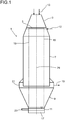
- FIG. 2 an arrangement of radially extending Vertropferkanälen different lengths is shown.
- the device for dripping has radially extending channels 25.
- a portion of the channels 25 extends into the middle of the reactor 1.
- Another portion of channels 24 projects less far into the reactor 1, so that in particular in the outer regions of the reactor, where the distance between the radially extending to the center the reactor 1 protruding channels 25 is large, further channels 24 are provided, can be introduced through the monomer solution in the reactor 1. This allows a more uniform distribution of the drops over the entire reactor cross-section.
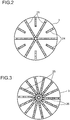
- FIG. 3 shows A corresponding star-shaped arrangement of the channels 25 .
- Other possible arrangements of the channels show the FIGS. 4 and 5 , In these, however, an arrangement with an angle ⁇ to the horizontal is difficult to realize, so that in this case the channels 25 preferably extend horizontally.
- FIG. 4 shows an arrangement in rectangular division, in which the individual channels 25 are each arranged at an angle of 90 ° to each other, so that each rectangles, preferably squares are formed by the intersections 27 of the channels.
- FIG. 5 shows an arrangement in triangular division.
- the channels 25 are each arranged at an angle of 60 ° to each other, so that 25 each equilateral triangles are formed by the intersections 27 of the channels.
- this also requires that the respective parallel channels always have the same distance.
- FIG. 3 shown star-shaped arrangement preferred.
- the number of channels may vary depending on the size of the reactor.
- a rotationally symmetrical arrangement is always preferred.
- the number of channels 24, 25 is chosen such that the ratio of the area covered by the channels 24, 25 or the droplet head in the reactor relative to the area defined by the circumference of a line along the outermost holes is smaller than 50%. This ensures that sufficient gas can flow past the channels 24, 25 and a sufficient contact between the gas and the channels 24, 25 leaving drops is realized.
- FIGS. 6, 7 and 8 are cross sections through channels 25 shown in different embodiments.
- the droplets formed at the outer holes in a channel exit at an angle to the vertical, that is to the reactor axis.
- the area of the channel in which the holes are formed, as in FIG. 6 shown to shape in the form of a circle segment.
- the angle a at which the monomer solution exits with respect to the reactor axis 29 increases from the center of the channel to the outside.
- the channel bottom in which the holes are formed to align at an angle to the horizontal, with holes perpendicular to the channel bottom 31 of the angle a, with the exit the drops to the reactor axis corresponds to the angle ⁇ of the channel bottom to the horizontal.
- a design is possible in which, in addition to the angled portions of the channel bottom 31, a middle bottom portion 33 extends horizontally.
- the holes are formed in dropletizing plates which are positioned at correspondingly shaped openings in the bottom of the channels 25.
- the dropletizer plates can then be removed for cleaning and replaced with clean dropletizer plates.
- the Vertropferplatten are preferably designed either in the form of a circle segment or angled so that a bottom profile of the channel 25 can be realized, as in the FIGS. 6 to 8 is shown.
- the angle at which the monomer solution emerges increases from the center of the reactor to the outside.
- the channels 25 are also possible to make the channels 25 with any other cross-section.
- Vertropferplatten it is particularly preferred to form the channels 25 with a rectangular cross-section.
- the channel can be closed at the top with a removable lid and the Vertropferplatten can be easily removed and replaced after removing the lid.
- FIG. 9 shows a plan view of a Vertropferplatte.
- a dropletizer plate 26 has a number of holes 35 through which the monomer solution is dropped into the reactor.
- the monomer solution flows through the holes 35 and decomposes after leaving the dropletizer plate 26 in drops. Drop generation takes place immediately after leaving the dropletizer plate 26.
- the number of holes in the dropletizer plate relative to the surface of the dropletizer plate 26 is selected such that the number of holes in the area of 1000 defined by the circumference of a line along the outermost holes 35 of the dropletizer plate 26 is 1000 to 15000 holes / m 2 , preferably in the range of 2000 to 12000 holes / m 2 and in particular in the range of 4000 to 10000 holes / m 2 .
- all Vertropferplatten the device for dropping 5 are considered in the reactor 1.
- the appropriate number of holes 35 a sufficiently large amount of drops is generated in order to operate the reactor economically, on the other hand, the number of drops must not be so large that individual drops collide and coalesce.
- the number of drops must therefore be chosen so that each drop is surrounded by a sufficiently large volume of gas, with which a collision with other drops can be largely avoided.
- a complete avoidance of drop collisions and coalescence of individual drops can not be achieved if the reactor is still to be operated economically.
- a substantial avoidance is achieved when the number of holes 35 in the droplet plate in the area described above with respect to the area defined by the circumference of a line along the outermost holes 35 of the dropletizing plate 26.
- a suitable spacing of the holes in a row of holes and the rows of holes is in the range from 1 to 100 mm, preferably in the range from 2 to 50 mm and in particular in the range from 3 to 20 mm.
Landscapes
- Chemical & Material Sciences (AREA)
- Chemical Kinetics & Catalysis (AREA)
- Organic Chemistry (AREA)
- Health & Medical Sciences (AREA)
- Medicinal Chemistry (AREA)
- Polymers & Plastics (AREA)
- Engineering & Computer Science (AREA)
- Combustion & Propulsion (AREA)
- Polymerisation Methods In General (AREA)
- Devices And Processes Conducted In The Presence Of Fluids And Solid Particles (AREA)
- Addition Polymer Or Copolymer, Post-Treatments, Or Chemical Modifications (AREA)
Claims (11)
- Dispositif pour l'introduction de gouttes d'une solution de monomères pour la fabrication de poly(méth)acrylate dans un réacteur (1) pour la polymérisation en gouttes, qui comprend au moins un canal (25) ou une tête de formation de gouttes, le canal (25) ou la tête de formation de gouttes étant fermé sur son côté inférieur avec une plaque de formation de gouttes (26), la plaque de formation de gouttes (26) comprenant des trous par lesquels la solution de monomères est introduite dans le réacteur (1) et la plaque de formation de gouttes (26) étant configurée de telle sorte que des trous (35) qui, dans une plaque de formation de gouttes (26) à symétrie axiale ou dans une plaque de formation de gouttes annulaire ou configurée sous la forme d'un segment d'anneau, ne se situent pas sur une ligne centrale de la plaque de formation de gouttes (26) ou qui, dans une plaque de formation de gouttes circulaire, ne se situent pas au centre de la plaque de formation de gouttes (26) sont orientés de telle sorte que la solution de monomères est introduite par les trous (35) dans le réacteur (1) à un angle par rapport à la verticale dans la plage allant de 0 à 30° et, en cas d'orientation radiale de plaques de formation de gouttes (26) à symétrie axiale, les trous (35) sont orientés de telle sorte que l'angle avec lequel la solution de monomères est introduite dans le réacteur (1) diminue dans la direction de l'axe du réacteur (1), et en cas de plaques de formation de gouttes (26) agencées en parallèle les unes par rapport aux autres ou de plaques de formation de gouttes agencées concentriquement, sont orientés respectivement sur une ligne parallèle à la ligne centrale ou sur une ligne agencée concentriquement autour du centre de telle sorte que l'angle avec lequel la solution de monomères est introduite dans le réacteur (1) soit constant et se situe dans la plage allant de 0 à 30°.
- Dispositif selon la revendication 1, caractérisé en ce qu'au moins deux agencements de distribution comprenant chacun au moins deux plaques de formation de gouttes (26) agencées en parallèle les unes par rapport aux autres sont agencés l'un par rapport à l'autre à un angle, de telle sorte qu'une division polygonale soit obtenue.
- Dispositif selon la revendication 1, caractérisé en ce qu'en cas d'agencement radial des plaques de formation de gouttes (26), l'angle décroissant avec lequel la solution de monomères est introduite dans le réacteur est obtenu par fermeture d'un canal d'au moins deux plaques de formation de gouttes (26) et l'angle avec lequel la solution de monomères est introduite goutte-à-goutte dans le réacteur (1) est constant pour chaque série de trous dans une plaque de formation de gouttes (26), les angles dans les plaques de formation de gouttes (26) plus proches du centre du réacteur (1) étant plus petits que les angles des plaques de formation de gouttes (26) qui sont agencées plus à l'extérieur.
- Dispositif selon la revendication 1 ou 3, caractérisé en ce qu'en cas d'agencement radial des plaques de formation de gouttes (26), l'angle avec lequel la solution de monomères est introduite dans le réacteur (1) augmente vers l'extérieur dans une plaque de formation de gouttes (26) depuis le centre du réacteur (1) .
- Dispositif selon la revendication 4, caractérisé en ce que l'angle α avec lequel la solution de monomères sort au moins des trous sur les bords radiaux se situe dans la plage définie ci-après :


- Dispositif selon l'une quelconque des revendications 1 à 5, caractérisé en ce qu'en cas de plaque de formation de gouttes (26) configurée à symétrie axiale ou sous la forme d'un anneau ou d'une section d'anneau, des trous le long de la ligne centrale parallèle à l'axe du canal (25) ou, en cas de plaque de formation de gouttes circulaire, au centre sont orientés de telle sorte que la solution de monomères qui est introduite par ces trous s'égoutte verticalement vers le bas.
- Dispositif selon l'une quelconque des revendications 1 à 6, caractérisé en ce que les plaques de formation de gouttes (26) présentent un profil à angle le long de leur ligne centrale, un profil à plusieurs angles symétriquement à la ligne centrale ou un profil sous la forme d'un segment de cercle.
- Dispositif selon l'une quelconque des revendications 1 à 7, caractérisé en ce qu'en cas d'agencement radial, parallèle ou annulaire des plaques de formation de gouttes (26), plusieurs canaux (25) sont compris, qui comprennent chacun une ou plusieurs plaques de formation de gouttes (26).
- Dispositif selon l'une quelconque des revendications 1 à 8, caractérisé en ce que l'écart entre les trous les plus extérieurs (35) d'une plaque de formation de gouttes (26) et le bord de la plaque de formation de gouttes (26) est d'au plus 200 mm.
- Dispositif selon l'une quelconque des revendications 1 à 9, caractérisé en ce que les trous présentent un diamètre dans la plage allant de 25 à 500 µm.
- Dispositif selon l'une quelconque des revendications 1 à 10, caractérisé en ce que les trous présentent un écart les uns des autres dans la plage allant de 1 à 100 mm.
Applications Claiming Priority (2)
| Application Number | Priority Date | Filing Date | Title |
|---|---|---|---|
| EP14173483 | 2014-06-23 | ||
| PCT/EP2015/064026 WO2015197571A1 (fr) | 2014-06-23 | 2015-06-23 | Dispositif pour l'introduction de gouttes d'une solution monomérique dans un réacteur |
Publications (2)
| Publication Number | Publication Date |
|---|---|
| EP3157665A1 EP3157665A1 (fr) | 2017-04-26 |
| EP3157665B1 true EP3157665B1 (fr) | 2018-08-15 |
Family
ID=50976539
Family Applications (1)
| Application Number | Title | Priority Date | Filing Date |
|---|---|---|---|
| EP15730202.7A Active EP3157665B1 (fr) | 2014-06-23 | 2015-06-23 | Dispositif pour l'introduction de gouttes d'une solution monomérique dans un réacteur |
Country Status (5)
| Country | Link |
|---|---|
| US (1) | US9925511B2 (fr) |
| EP (1) | EP3157665B1 (fr) |
| JP (1) | JP6598805B2 (fr) |
| CN (1) | CN106573217B (fr) |
| WO (1) | WO2015197571A1 (fr) |
Families Citing this family (5)
| Publication number | Priority date | Publication date | Assignee | Title |
|---|---|---|---|---|
| US11332550B2 (en) | 2017-03-01 | 2022-05-17 | Basf Se | Device and method for producing powdered polymers |
| JP7160841B2 (ja) * | 2017-05-31 | 2022-10-25 | ビーエーエスエフ ソシエタス・ヨーロピア | 流動底部ならびにこのような流動底部を有する装置 |
| WO2019158511A1 (fr) * | 2018-02-14 | 2019-08-22 | Basf Se | Procédé de nettoyage de plaques perforées |
| JP7101070B2 (ja) * | 2018-07-26 | 2022-07-14 | デクセリアルズ株式会社 | 樹脂粒子の製造方法 |
| CN113996079B (zh) * | 2021-11-18 | 2022-12-27 | 重庆格林嘉科技有限公司 | 一种穿流型型材塔板的结构及安装方法 |
Family Cites Families (15)
| Publication number | Priority date | Publication date | Assignee | Title |
|---|---|---|---|---|
| DE2951045C2 (de) * | 1979-12-19 | 1983-12-22 | Röhm GmbH, 6100 Darmstadt | Herstellung von schlagzähen Harzen |
| JPH0789900A (ja) * | 1993-07-29 | 1995-04-04 | Asahi Chem Ind Co Ltd | プラスチックから高品質モノマーを回収する方法 |
| US6369135B1 (en) * | 1995-08-15 | 2002-04-09 | Georgia Tech Research Corporation | Water-borne alkyd coatings by miniemulsion polymerization |
| AUPO669697A0 (en) * | 1997-05-08 | 1997-06-05 | Unisearch Limited | Polymerisation reactions under miniemulsion conditions |
| HRP980257B1 (en) * | 1997-05-28 | 2002-08-31 | Messer Griesheim Gmbh | Apparatus and method for conducting reactions in fluidized particle layers |
| US6855761B2 (en) * | 1999-04-23 | 2005-02-15 | Tosoh Corporation | Monodisperse particles, process for producing the same, and uses thereof |
| US7007932B2 (en) * | 2003-07-25 | 2006-03-07 | Air Products And Chemicals, Inc. | Wall-flow redistributor for packed columns |
| US7727586B2 (en) | 2005-01-28 | 2010-06-01 | Basf Aktiengesellschaft | Production of water-absorbing polymeric particles by dropletization polymerization in the gas phase |
| DE102005042608A1 (de) * | 2005-09-07 | 2007-03-08 | Basf Ag | Polymerisationsverfahren |
| DE102005044035A1 (de) * | 2005-09-14 | 2007-03-15 | Basf Ag | Verfahren zum Vertropfen von Flüssigkeiten |
| ATE491729T1 (de) | 2006-10-05 | 2011-01-15 | Basf Se | Verfahren zur herstellung wasserabsorbierender polymerpartikel durch polymerisation von tropfen einer monomerlösung |
| WO2008086976A1 (fr) | 2007-01-16 | 2008-07-24 | Basf Se | Procédé de fabrication de particules polymères par polymérisation de gouttes de liquide dans une phase gazeuse |
| US8546498B2 (en) | 2008-07-07 | 2013-10-01 | Basf Se | Method for producing water-absorbing polymer particles by polymerizing droplets of a monomer solution |
| US8883939B2 (en) * | 2009-02-02 | 2014-11-11 | Basf Se | Method for producing polymers and reactor for carrying out said method |
| US8481159B2 (en) | 2009-09-04 | 2013-07-09 | Basf Se | Water-absorbent porous polymer particles having specific sphericity and high bulk density |
-
2015
- 2015-06-23 JP JP2016575116A patent/JP6598805B2/ja active Active
- 2015-06-23 EP EP15730202.7A patent/EP3157665B1/fr active Active
- 2015-06-23 WO PCT/EP2015/064026 patent/WO2015197571A1/fr not_active Ceased
- 2015-06-23 US US15/320,771 patent/US9925511B2/en active Active
- 2015-06-23 CN CN201580045138.6A patent/CN106573217B/zh active Active
Non-Patent Citations (1)
| Title |
|---|
| None * |
Also Published As
| Publication number | Publication date |
|---|---|
| JP2017524769A (ja) | 2017-08-31 |
| WO2015197571A1 (fr) | 2015-12-30 |
| US20170232418A1 (en) | 2017-08-17 |
| JP6598805B2 (ja) | 2019-10-30 |
| US9925511B2 (en) | 2018-03-27 |
| EP3157665A1 (fr) | 2017-04-26 |
| CN106573217B (zh) | 2019-08-06 |
| CN106573217A (zh) | 2017-04-19 |
Similar Documents
| Publication | Publication Date | Title |
|---|---|---|
| EP3157665B1 (fr) | Dispositif pour l'introduction de gouttes d'une solution monomérique dans un réacteur | |
| EP1395358B1 (fr) | Dispositif pour traiter une matiere particulaire | |
| EP1232003A2 (fr) | Dispositif de revetement de particules | |
| DE2332948C2 (de) | Verfahren und Vorrichtung zum Mischen von teilchenförmigen Feststoffen | |
| EP1735067B1 (fr) | Colonne de distillation avec un mélangeur en ligne dans l'alimentation | |
| EP1049531A1 (fr) | Dispositif permettant de melanger puis de pulveriser des liquides | |
| EP1278597B1 (fr) | Element fond d'un dispositif de traitement d'un produit particulaire | |
| EP3157962B1 (fr) | Dispositif de fabrication de poly(méth)acrylate pulvérulent | |
| EP3157661B1 (fr) | Dispositif pour l'addition de gouttes d'une solution monomérique dans un réacteur | |
| EP2163300B1 (fr) | Utilisation d'une plaque de distribution d'écoulements fluidiques | |
| DE69416273T2 (de) | Verfahren und Vorrichtung zur gleichmässigen Beschichtung von Katalysatorröhren | |
| WO2018158191A1 (fr) | Dispositif et procédé pour produire des polymères pulvérulents | |
| EP3265221B1 (fr) | Système pour fabriquer du poly(méth)acrylate pulvérulent | |
| EP3265222B1 (fr) | Système pour fabriquer du poly(méth)acrylate pulvérulent | |
| EP2720785B1 (fr) | Dispositif destiné au traitement de matières particulaires | |
| EP2490797B1 (fr) | Dispositif de traitement de produit particulaire comprenant une base de circulation à double flux | |
| WO2017085093A1 (fr) | Dispositif servant à produire du poly(méth)acrylate pulvérulent | |
| EP2861396A1 (fr) | Plaque à buses pour un dispositif de granulation et dispositif de granulation comprenant une plaque à buses | |
| WO2016169909A1 (fr) | Dispositif servant à produire du poly(méth)acrylate pulvérulent | |
| DE3104062A1 (de) | "verfahren zum mischen eines gemenges von pulverisierten bestandteilen und vorrichtung zur durchfuehrung des verfahrens" | |
| EP3189887A1 (fr) | Réacteur à cavitation destiné à traiter des substances pouvant s'écouler | |
| DE2411024C3 (de) | Verfahren und Vorrichtung zur Zuführung von flüssigem Material in einen Spritzkorb eines Prillturmes | |
| DE1782920A1 (de) | Verfahren zum isolieren von elastomeren aus ihren loesungen in organischen loesungsmitteln | |
| DE2411024B2 (de) | Verfahren und Vorrichtung zur Zuführung von flüssigem Material in einen Spritzkorb eines Prillturmes | |
| DE20121942U1 (de) | Vorrichtung zum Mischen von Flüssigkeiten |
Legal Events
| Date | Code | Title | Description |
|---|---|---|---|
| STAA | Information on the status of an ep patent application or granted ep patent |
Free format text: STATUS: THE INTERNATIONAL PUBLICATION HAS BEEN MADE |
|
| PUAI | Public reference made under article 153(3) epc to a published international application that has entered the european phase |
Free format text: ORIGINAL CODE: 0009012 |
|
| STAA | Information on the status of an ep patent application or granted ep patent |
Free format text: STATUS: REQUEST FOR EXAMINATION WAS MADE |
|
| 17P | Request for examination filed |
Effective date: 20170123 |
|
| AK | Designated contracting states |
Kind code of ref document: A1 Designated state(s): AL AT BE BG CH CY CZ DE DK EE ES FI FR GB GR HR HU IE IS IT LI LT LU LV MC MK MT NL NO PL PT RO RS SE SI SK SM TR |
|
| AX | Request for extension of the european patent |
Extension state: BA ME |
|
| DAV | Request for validation of the european patent (deleted) | ||
| DAX | Request for extension of the european patent (deleted) | ||
| GRAP | Despatch of communication of intention to grant a patent |
Free format text: ORIGINAL CODE: EPIDOSNIGR1 |
|
| STAA | Information on the status of an ep patent application or granted ep patent |
Free format text: STATUS: GRANT OF PATENT IS INTENDED |
|
| INTG | Intention to grant announced |
Effective date: 20180123 |
|
| GRAS | Grant fee paid |
Free format text: ORIGINAL CODE: EPIDOSNIGR3 |
|
| GRAA | (expected) grant |
Free format text: ORIGINAL CODE: 0009210 |
|
| STAA | Information on the status of an ep patent application or granted ep patent |
Free format text: STATUS: THE PATENT HAS BEEN GRANTED |
|
| AK | Designated contracting states |
Kind code of ref document: B1 Designated state(s): AL AT BE BG CH CY CZ DE DK EE ES FI FR GB GR HR HU IE IS IT LI LT LU LV MC MK MT NL NO PL PT RO RS SE SI SK SM TR |
|
| REG | Reference to a national code |
Ref country code: CH Ref legal event code: EP Ref country code: GB Ref legal event code: FG4D Free format text: NOT ENGLISH Ref country code: AT Ref legal event code: REF Ref document number: 1029123 Country of ref document: AT Kind code of ref document: T Effective date: 20180815 |
|
| REG | Reference to a national code |
Ref country code: IE Ref legal event code: FG4D Free format text: LANGUAGE OF EP DOCUMENT: GERMAN |
|
| REG | Reference to a national code |
Ref country code: DE Ref legal event code: R096 Ref document number: 502015005453 Country of ref document: DE |
|
| REG | Reference to a national code |
Ref country code: NL Ref legal event code: MP Effective date: 20180815 |
|
| REG | Reference to a national code |
Ref country code: LT Ref legal event code: MG4D |
|
| PG25 | Lapsed in a contracting state [announced via postgrant information from national office to epo] |
Ref country code: LT Free format text: LAPSE BECAUSE OF FAILURE TO SUBMIT A TRANSLATION OF THE DESCRIPTION OR TO PAY THE FEE WITHIN THE PRESCRIBED TIME-LIMIT Effective date: 20180815 Ref country code: RS Free format text: LAPSE BECAUSE OF FAILURE TO SUBMIT A TRANSLATION OF THE DESCRIPTION OR TO PAY THE FEE WITHIN THE PRESCRIBED TIME-LIMIT Effective date: 20180815 Ref country code: FI Free format text: LAPSE BECAUSE OF FAILURE TO SUBMIT A TRANSLATION OF THE DESCRIPTION OR TO PAY THE FEE WITHIN THE PRESCRIBED TIME-LIMIT Effective date: 20180815 Ref country code: NL Free format text: LAPSE BECAUSE OF FAILURE TO SUBMIT A TRANSLATION OF THE DESCRIPTION OR TO PAY THE FEE WITHIN THE PRESCRIBED TIME-LIMIT Effective date: 20180815 Ref country code: IS Free format text: LAPSE BECAUSE OF FAILURE TO SUBMIT A TRANSLATION OF THE DESCRIPTION OR TO PAY THE FEE WITHIN THE PRESCRIBED TIME-LIMIT Effective date: 20181215 Ref country code: BG Free format text: LAPSE BECAUSE OF FAILURE TO SUBMIT A TRANSLATION OF THE DESCRIPTION OR TO PAY THE FEE WITHIN THE PRESCRIBED TIME-LIMIT Effective date: 20181115 Ref country code: NO Free format text: LAPSE BECAUSE OF FAILURE TO SUBMIT A TRANSLATION OF THE DESCRIPTION OR TO PAY THE FEE WITHIN THE PRESCRIBED TIME-LIMIT Effective date: 20181115 Ref country code: GR Free format text: LAPSE BECAUSE OF FAILURE TO SUBMIT A TRANSLATION OF THE DESCRIPTION OR TO PAY THE FEE WITHIN THE PRESCRIBED TIME-LIMIT Effective date: 20181116 Ref country code: SE Free format text: LAPSE BECAUSE OF FAILURE TO SUBMIT A TRANSLATION OF THE DESCRIPTION OR TO PAY THE FEE WITHIN THE PRESCRIBED TIME-LIMIT Effective date: 20180815 |
|
| PG25 | Lapsed in a contracting state [announced via postgrant information from national office to epo] |
Ref country code: HR Free format text: LAPSE BECAUSE OF FAILURE TO SUBMIT A TRANSLATION OF THE DESCRIPTION OR TO PAY THE FEE WITHIN THE PRESCRIBED TIME-LIMIT Effective date: 20180815 Ref country code: AL Free format text: LAPSE BECAUSE OF FAILURE TO SUBMIT A TRANSLATION OF THE DESCRIPTION OR TO PAY THE FEE WITHIN THE PRESCRIBED TIME-LIMIT Effective date: 20180815 Ref country code: LV Free format text: LAPSE BECAUSE OF FAILURE TO SUBMIT A TRANSLATION OF THE DESCRIPTION OR TO PAY THE FEE WITHIN THE PRESCRIBED TIME-LIMIT Effective date: 20180815 |
|
| PG25 | Lapsed in a contracting state [announced via postgrant information from national office to epo] |
Ref country code: CZ Free format text: LAPSE BECAUSE OF FAILURE TO SUBMIT A TRANSLATION OF THE DESCRIPTION OR TO PAY THE FEE WITHIN THE PRESCRIBED TIME-LIMIT Effective date: 20180815 Ref country code: ES Free format text: LAPSE BECAUSE OF FAILURE TO SUBMIT A TRANSLATION OF THE DESCRIPTION OR TO PAY THE FEE WITHIN THE PRESCRIBED TIME-LIMIT Effective date: 20180815 Ref country code: EE Free format text: LAPSE BECAUSE OF FAILURE TO SUBMIT A TRANSLATION OF THE DESCRIPTION OR TO PAY THE FEE WITHIN THE PRESCRIBED TIME-LIMIT Effective date: 20180815 Ref country code: PL Free format text: LAPSE BECAUSE OF FAILURE TO SUBMIT A TRANSLATION OF THE DESCRIPTION OR TO PAY THE FEE WITHIN THE PRESCRIBED TIME-LIMIT Effective date: 20180815 Ref country code: RO Free format text: LAPSE BECAUSE OF FAILURE TO SUBMIT A TRANSLATION OF THE DESCRIPTION OR TO PAY THE FEE WITHIN THE PRESCRIBED TIME-LIMIT Effective date: 20180815 Ref country code: IT Free format text: LAPSE BECAUSE OF FAILURE TO SUBMIT A TRANSLATION OF THE DESCRIPTION OR TO PAY THE FEE WITHIN THE PRESCRIBED TIME-LIMIT Effective date: 20180815 |
|
| REG | Reference to a national code |
Ref country code: DE Ref legal event code: R097 Ref document number: 502015005453 Country of ref document: DE |
|
| PG25 | Lapsed in a contracting state [announced via postgrant information from national office to epo] |
Ref country code: DK Free format text: LAPSE BECAUSE OF FAILURE TO SUBMIT A TRANSLATION OF THE DESCRIPTION OR TO PAY THE FEE WITHIN THE PRESCRIBED TIME-LIMIT Effective date: 20180815 Ref country code: SM Free format text: LAPSE BECAUSE OF FAILURE TO SUBMIT A TRANSLATION OF THE DESCRIPTION OR TO PAY THE FEE WITHIN THE PRESCRIBED TIME-LIMIT Effective date: 20180815 Ref country code: SK Free format text: LAPSE BECAUSE OF FAILURE TO SUBMIT A TRANSLATION OF THE DESCRIPTION OR TO PAY THE FEE WITHIN THE PRESCRIBED TIME-LIMIT Effective date: 20180815 |
|
| PLBE | No opposition filed within time limit |
Free format text: ORIGINAL CODE: 0009261 |
|
| STAA | Information on the status of an ep patent application or granted ep patent |
Free format text: STATUS: NO OPPOSITION FILED WITHIN TIME LIMIT |
|
| 26N | No opposition filed |
Effective date: 20190516 |
|
| PG25 | Lapsed in a contracting state [announced via postgrant information from national office to epo] |
Ref country code: SI Free format text: LAPSE BECAUSE OF FAILURE TO SUBMIT A TRANSLATION OF THE DESCRIPTION OR TO PAY THE FEE WITHIN THE PRESCRIBED TIME-LIMIT Effective date: 20180815 |
|
| PG25 | Lapsed in a contracting state [announced via postgrant information from national office to epo] |
Ref country code: MC Free format text: LAPSE BECAUSE OF FAILURE TO SUBMIT A TRANSLATION OF THE DESCRIPTION OR TO PAY THE FEE WITHIN THE PRESCRIBED TIME-LIMIT Effective date: 20180815 |
|
| REG | Reference to a national code |
Ref country code: CH Ref legal event code: PL |
|
| GBPC | Gb: european patent ceased through non-payment of renewal fee |
Effective date: 20190623 |
|
| PG25 | Lapsed in a contracting state [announced via postgrant information from national office to epo] |
Ref country code: TR Free format text: LAPSE BECAUSE OF FAILURE TO SUBMIT A TRANSLATION OF THE DESCRIPTION OR TO PAY THE FEE WITHIN THE PRESCRIBED TIME-LIMIT Effective date: 20180815 |
|
| PG25 | Lapsed in a contracting state [announced via postgrant information from national office to epo] |
Ref country code: GB Free format text: LAPSE BECAUSE OF NON-PAYMENT OF DUE FEES Effective date: 20190623 Ref country code: IE Free format text: LAPSE BECAUSE OF NON-PAYMENT OF DUE FEES Effective date: 20190623 |
|
| PG25 | Lapsed in a contracting state [announced via postgrant information from national office to epo] |
Ref country code: LI Free format text: LAPSE BECAUSE OF NON-PAYMENT OF DUE FEES Effective date: 20190630 Ref country code: LU Free format text: LAPSE BECAUSE OF NON-PAYMENT OF DUE FEES Effective date: 20190623 Ref country code: CH Free format text: LAPSE BECAUSE OF NON-PAYMENT OF DUE FEES Effective date: 20190630 |
|
| PG25 | Lapsed in a contracting state [announced via postgrant information from national office to epo] |
Ref country code: FR Free format text: LAPSE BECAUSE OF NON-PAYMENT OF DUE FEES Effective date: 20190630 Ref country code: PT Free format text: LAPSE BECAUSE OF FAILURE TO SUBMIT A TRANSLATION OF THE DESCRIPTION OR TO PAY THE FEE WITHIN THE PRESCRIBED TIME-LIMIT Effective date: 20181215 |
|
| PG25 | Lapsed in a contracting state [announced via postgrant information from national office to epo] |
Ref country code: CY Free format text: LAPSE BECAUSE OF FAILURE TO SUBMIT A TRANSLATION OF THE DESCRIPTION OR TO PAY THE FEE WITHIN THE PRESCRIBED TIME-LIMIT Effective date: 20180815 |
|
| PG25 | Lapsed in a contracting state [announced via postgrant information from national office to epo] |
Ref country code: MT Free format text: LAPSE BECAUSE OF FAILURE TO SUBMIT A TRANSLATION OF THE DESCRIPTION OR TO PAY THE FEE WITHIN THE PRESCRIBED TIME-LIMIT Effective date: 20180815 Ref country code: HU Free format text: LAPSE BECAUSE OF FAILURE TO SUBMIT A TRANSLATION OF THE DESCRIPTION OR TO PAY THE FEE WITHIN THE PRESCRIBED TIME-LIMIT; INVALID AB INITIO Effective date: 20150623 |
|
| REG | Reference to a national code |
Ref country code: AT Ref legal event code: MM01 Ref document number: 1029123 Country of ref document: AT Kind code of ref document: T Effective date: 20200623 |
|
| PG25 | Lapsed in a contracting state [announced via postgrant information from national office to epo] |
Ref country code: AT Free format text: LAPSE BECAUSE OF NON-PAYMENT OF DUE FEES Effective date: 20200623 |
|
| PG25 | Lapsed in a contracting state [announced via postgrant information from national office to epo] |
Ref country code: MK Free format text: LAPSE BECAUSE OF FAILURE TO SUBMIT A TRANSLATION OF THE DESCRIPTION OR TO PAY THE FEE WITHIN THE PRESCRIBED TIME-LIMIT Effective date: 20180815 |
|
| PGFP | Annual fee paid to national office [announced via postgrant information from national office to epo] |
Ref country code: DE Payment date: 20250626 Year of fee payment: 11 |
|
| PGFP | Annual fee paid to national office [announced via postgrant information from national office to epo] |
Ref country code: BE Payment date: 20250624 Year of fee payment: 11 |