EP3158162B1 - Système de stimulation de fond de trou - Google Patents
Système de stimulation de fond de trou Download PDFInfo
- Publication number
- EP3158162B1 EP3158162B1 EP15731038.4A EP15731038A EP3158162B1 EP 3158162 B1 EP3158162 B1 EP 3158162B1 EP 15731038 A EP15731038 A EP 15731038A EP 3158162 B1 EP3158162 B1 EP 3158162B1
- Authority
- EP
- European Patent Office
- Prior art keywords
- well
- stimulation system
- tubular structure
- aperture
- annular barrier
- Prior art date
- Legal status (The legal status is an assumption and is not a legal conclusion. Google has not performed a legal analysis and makes no representation as to the accuracy of the status listed.)
- Not-in-force
Links
- 230000000638 stimulation Effects 0.000 title claims description 45
- 230000004888 barrier function Effects 0.000 claims description 78
- 239000012530 fluid Substances 0.000 claims description 69
- 238000004519 manufacturing process Methods 0.000 claims description 31
- 239000002184 metal Substances 0.000 claims description 23
- 230000015572 biosynthetic process Effects 0.000 claims description 11
- 238000001514 detection method Methods 0.000 claims description 11
- 230000004936 stimulating effect Effects 0.000 claims description 9
- 238000006073 displacement reaction Methods 0.000 claims description 8
- 239000000463 material Substances 0.000 claims description 7
- 238000000034 method Methods 0.000 claims description 6
- 239000003921 oil Substances 0.000 description 9
- 239000007789 gas Substances 0.000 description 6
- 230000004913 activation Effects 0.000 description 5
- VNWKTOKETHGBQD-UHFFFAOYSA-N methane Chemical compound C VNWKTOKETHGBQD-UHFFFAOYSA-N 0.000 description 4
- XLYOFNOQVPJJNP-UHFFFAOYSA-N water Substances O XLYOFNOQVPJJNP-UHFFFAOYSA-N 0.000 description 4
- 239000011148 porous material Substances 0.000 description 3
- 239000004215 Carbon black (E152) Substances 0.000 description 2
- 230000003213 activating effect Effects 0.000 description 2
- 239000004964 aerogel Substances 0.000 description 2
- 239000010779 crude oil Substances 0.000 description 2
- 239000002178 crystalline material Substances 0.000 description 2
- 230000003247 decreasing effect Effects 0.000 description 2
- 239000006260 foam Substances 0.000 description 2
- 229930195733 hydrocarbon Natural products 0.000 description 2
- 150000002430 hydrocarbons Chemical class 0.000 description 2
- 239000000203 mixture Substances 0.000 description 2
- 239000003345 natural gas Substances 0.000 description 2
- 230000007935 neutral effect Effects 0.000 description 2
- 238000003825 pressing Methods 0.000 description 2
- 239000011347 resin Substances 0.000 description 2
- 229920005989 resin Polymers 0.000 description 2
- 239000000654 additive Substances 0.000 description 1
- 230000000996 additive effect Effects 0.000 description 1
- 239000000919 ceramic Substances 0.000 description 1
- 239000002131 composite material Substances 0.000 description 1
- 150000001875 compounds Chemical class 0.000 description 1
- 238000010586 diagram Methods 0.000 description 1
- 230000000694 effects Effects 0.000 description 1
- 239000011521 glass Substances 0.000 description 1
- 238000002955 isolation Methods 0.000 description 1
- 239000011499 joint compound Substances 0.000 description 1
- 239000004005 microsphere Substances 0.000 description 1
- 238000012986 modification Methods 0.000 description 1
- 230000004048 modification Effects 0.000 description 1
- 239000002245 particle Substances 0.000 description 1
- 230000008569 process Effects 0.000 description 1
- 239000008262 pumice Substances 0.000 description 1
- 239000000126 substance Substances 0.000 description 1
- 229910052845 zircon Inorganic materials 0.000 description 1
- GFQYVLUOOAAOGM-UHFFFAOYSA-N zirconium(iv) silicate Chemical compound [Zr+4].[O-][Si]([O-])([O-])[O-] GFQYVLUOOAAOGM-UHFFFAOYSA-N 0.000 description 1
Images


Classifications
-
- E—FIXED CONSTRUCTIONS
- E21—EARTH OR ROCK DRILLING; MINING
- E21B—EARTH OR ROCK DRILLING; OBTAINING OIL, GAS, WATER, SOLUBLE OR MELTABLE MATERIALS OR A SLURRY OF MINERALS FROM WELLS
- E21B43/00—Methods or apparatus for obtaining oil, gas, water, soluble or meltable materials or a slurry of minerals from wells
- E21B43/25—Methods for stimulating production
- E21B43/26—Methods for stimulating production by forming crevices or fractures
-
- E—FIXED CONSTRUCTIONS
- E21—EARTH OR ROCK DRILLING; MINING
- E21B—EARTH OR ROCK DRILLING; OBTAINING OIL, GAS, WATER, SOLUBLE OR MELTABLE MATERIALS OR A SLURRY OF MINERALS FROM WELLS
- E21B23/00—Apparatus for displacing, setting, locking, releasing or removing tools, packers or the like in boreholes or wells
-
- E—FIXED CONSTRUCTIONS
- E21—EARTH OR ROCK DRILLING; MINING
- E21B—EARTH OR ROCK DRILLING; OBTAINING OIL, GAS, WATER, SOLUBLE OR MELTABLE MATERIALS OR A SLURRY OF MINERALS FROM WELLS
- E21B33/00—Sealing or packing boreholes or wells
- E21B33/10—Sealing or packing boreholes or wells in the borehole
- E21B33/12—Packers; Plugs
- E21B33/124—Units with longitudinally-spaced plugs for isolating the intermediate space
- E21B33/1243—Units with longitudinally-spaced plugs for isolating the intermediate space with inflatable sleeves
-
- E—FIXED CONSTRUCTIONS
- E21—EARTH OR ROCK DRILLING; MINING
- E21B—EARTH OR ROCK DRILLING; OBTAINING OIL, GAS, WATER, SOLUBLE OR MELTABLE MATERIALS OR A SLURRY OF MINERALS FROM WELLS
- E21B33/00—Sealing or packing boreholes or wells
- E21B33/10—Sealing or packing boreholes or wells in the borehole
- E21B33/12—Packers; Plugs
- E21B33/124—Units with longitudinally-spaced plugs for isolating the intermediate space
- E21B33/1243—Units with longitudinally-spaced plugs for isolating the intermediate space with inflatable sleeves
- E21B33/1246—Units with longitudinally-spaced plugs for isolating the intermediate space with inflatable sleeves inflated by down-hole pumping means operated by a pipe string
-
- E—FIXED CONSTRUCTIONS
- E21—EARTH OR ROCK DRILLING; MINING
- E21B—EARTH OR ROCK DRILLING; OBTAINING OIL, GAS, WATER, SOLUBLE OR MELTABLE MATERIALS OR A SLURRY OF MINERALS FROM WELLS
- E21B33/00—Sealing or packing boreholes or wells
- E21B33/10—Sealing or packing boreholes or wells in the borehole
- E21B33/12—Packers; Plugs
- E21B33/127—Packers; Plugs with inflatable sleeve
-
- E—FIXED CONSTRUCTIONS
- E21—EARTH OR ROCK DRILLING; MINING
- E21B—EARTH OR ROCK DRILLING; OBTAINING OIL, GAS, WATER, SOLUBLE OR MELTABLE MATERIALS OR A SLURRY OF MINERALS FROM WELLS
- E21B34/00—Valve arrangements for boreholes or wells
- E21B34/06—Valve arrangements for boreholes or wells in wells
- E21B34/10—Valve arrangements for boreholes or wells in wells operated by control fluid supplied from outside the borehole
-
- E—FIXED CONSTRUCTIONS
- E21—EARTH OR ROCK DRILLING; MINING
- E21B—EARTH OR ROCK DRILLING; OBTAINING OIL, GAS, WATER, SOLUBLE OR MELTABLE MATERIALS OR A SLURRY OF MINERALS FROM WELLS
- E21B34/00—Valve arrangements for boreholes or wells
- E21B34/06—Valve arrangements for boreholes or wells in wells
- E21B34/14—Valve arrangements for boreholes or wells in wells operated by movement of tools, e.g. sleeve valves operated by pistons or wire line tools
-
- E—FIXED CONSTRUCTIONS
- E21—EARTH OR ROCK DRILLING; MINING
- E21B—EARTH OR ROCK DRILLING; OBTAINING OIL, GAS, WATER, SOLUBLE OR MELTABLE MATERIALS OR A SLURRY OF MINERALS FROM WELLS
- E21B43/00—Methods or apparatus for obtaining oil, gas, water, soluble or meltable materials or a slurry of minerals from wells
- E21B43/14—Obtaining from a multiple-zone well
-
- E—FIXED CONSTRUCTIONS
- E21—EARTH OR ROCK DRILLING; MINING
- E21B—EARTH OR ROCK DRILLING; OBTAINING OIL, GAS, WATER, SOLUBLE OR MELTABLE MATERIALS OR A SLURRY OF MINERALS FROM WELLS
- E21B43/00—Methods or apparatus for obtaining oil, gas, water, soluble or meltable materials or a slurry of minerals from wells
- E21B43/25—Methods for stimulating production
- E21B43/26—Methods for stimulating production by forming crevices or fractures
- E21B43/267—Methods for stimulating production by forming crevices or fractures reinforcing fractures by propping
-
- E—FIXED CONSTRUCTIONS
- E21—EARTH OR ROCK DRILLING; MINING
- E21B—EARTH OR ROCK DRILLING; OBTAINING OIL, GAS, WATER, SOLUBLE OR MELTABLE MATERIALS OR A SLURRY OF MINERALS FROM WELLS
- E21B2200/00—Special features related to earth drilling for obtaining oil, gas or water
- E21B2200/06—Sleeve valves
-
- E—FIXED CONSTRUCTIONS
- E21—EARTH OR ROCK DRILLING; MINING
- E21B—EARTH OR ROCK DRILLING; OBTAINING OIL, GAS, WATER, SOLUBLE OR MELTABLE MATERIALS OR A SLURRY OF MINERALS FROM WELLS
- E21B47/00—Survey of boreholes or wells
Definitions
- the present invention relates to a downhole stimulation system for stimulating production of fluid from a well.
- the present invention further relates to a downhole stimulation method for stimulating production of fluid from a well by means of the downhole stimulation system according to the present invention.
- One of the last steps in completing a well and bringing it into production is to expand expandable sleeves of annular barriers to isolate a production zone, and then the formation in the production zone is fractured in order to increase reservoir contact.
- the fracturing operation is performed by opening the frac ports and ejecting fluid out through the ports.
- a system having a drop device is known from EP-A1-2,728,108 .
- a downhole stimulation system for stimulating production of fluid from a well having a top comprising:
- the proppants may be made of a material having a positive buoyancy in the fluid.
- the displacement means may be an element having an outer element diameter which is substantially equal to the inner diameter of the well tubular structure.
- Said displacement means may be a fluid, such as water.
- the expandable sleeve may be a metal sleeve.
- the downhole stimulation system as described above may further comprise a third annular barrier arranged closer to the top than the first annular barrier and a fourth annular barrier arranged further away from the top than the second annular barrier, the inflatable device being inflated between the second annular barrier and the fourth annular barrier.
- the tool may comprise several keys arranged at a distance from each other.
- the profile may be a circumferential groove.
- sliding sleeve may be a self-closing sleeve.
- the sliding sleeve may comprise a spring for closing the sleeve.
- a valve may be arranged in the aperture of at least one of the annular barriers.
- Said valve may be a one-way valve.
- a diameter of the tool body may be smaller than an inner diameter of the well tubular structure, defining a fluid passage between the tool and the well tubular structure.
- the tool may comprise an inflation pump for inflating the inflatable device.
- the tool may comprise a motor for driving the inflation pump.
- the expandable sleeve may have a fracturing device arranged on the outer face of the expandable sleeve for fracturing the formation when the outer face is pressed against the wall of the borehole.
- the sliding sleeve and/or the aperture may comprise an identification tag.
- the tool may comprise a detection unit for detecting the sliding sleeve and/or the aperture.
- Said detection unit may comprise a tag identification means for detecting the sliding sleeve and/or the aperture.
- sliding sleeve or annular barrier may comprise an identification tag.
- the detection unit may be adapted to detect the profile of the sliding sleeve and the aperture of the annular barrier in order to detect the first distance between the profile and the aperture.
- the tool may comprise an activation means for activating the inflation pump so that the inflatable device is inflated and for stopping the inflation pump so that the inflatable device is deflated.
- the key of the tool may be arranged at a second distance from the inflatable device of the tool, the second distance being equal to or larger than the first distance.
- said second distance may be adjustable.
- the tool body may comprise a telescopic body arranged between the key and the inflatable device, the telescopic body being adapted to adjust the second distance in relation to the detected first distance.
- the downhole stimulation system as described above may further comprise an activation sensor adapted to cause the inflatable device to deflate when a condition in the well changes.
- the tool may further comprise a detection sensor for detecting a condition of the well and/or the sleeve.
- the tool may comprise a communication unit for loading information from a reservoir sensor.
- the tool may further comprise a self-propelling means, such as a turbine or a propeller.
- a self-propelling means such as a turbine or a propeller.
- the well tubular structure may comprise a plurality of sliding sleeves, each sliding sleeve having an identification tag.
- At least one of the annular barriers may have at least one intermediate sleeve between the expandable sleeve and the tubular part.
- the expandable sleeve may comprise an opening.
- the tool may be wireless and may comprise a power supply.
- the tool may be connected and powered through a wireline.
- the present invention also relates to a downhole stimulation method for stimulating production of fluid from a well by means of the downhole stimulation system according to any of the preceding claims, comprising the steps of:
- the downhole stimulation method as described above may further comprise the step of deflating the inflatable device when a predetermined pressure or sequence of pressures is reached.
- the downhole stimulation method as described above may comprise the following steps:
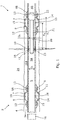
- Fig. 1 shows a downhole stimulation system 1 for stimulating production of hydrocarbon-containing fluid from a well 2.
- the downhole stimulation system 1 comprises a well tubular structure 4 and a first annular barrier 6, 6A and a second annular barrier 6, 6B for isolating a production zone 101.
- the first annular barrier 6, 6A is arranged closest to a top of the well 2.
- Each annular barrier 6, 6A, 6B comprises a tubular metal part 7 mounted as part of the well tubular structure 4 and an expandable sleeve 9 surrounding the tubular metal part and having an inner face 10 facing the tubular metal part and an outer face 11 facing the wall of the borehole.
- Each end 12, 13 of the expandable sleeve 9 is connected with the tubular metal part 7, defining an annular space 14 between the inner face 10 of the expandable sleeve and the tubular metal part.
- the annular barrier further comprises an aperture 15 arranged in the tubular metal part 7 for letting fluid into the annular space 14.
- the downhole stimulation system 1 comprises a pump 16 adapted to provide pressurised fluid down the well tubular structure 4 in order to stimulate the well 2, and the pump may also be used for expanding the expandable sleeves 9 of the annular barriers 6, 6A, 6B by letting pressurised fluid in through the aperture 15.
- the downhole stimulation system 1 further comprises a sliding sleeve 17 having at least one profile 18, and the sliding sleeve 17 is arranged between two annular barriers 6, 6A, 6B and has a closed position and an open position. In the open position, the sliding sleeve 17 allows fluid communication between the inside of the well tubular structure 4 and the production zone 101 through an opening 19 in the well tubular structure 4.
- the profile 18 of the sliding sleeve 17 is positioned at a first distance X a from the aperture 15 of the annular space 14.
- the downhole stimulation system 1 comprises a downhole tool 20 for bringing the sliding sleeve 17 from the closed position to the open position.
- the downhole tool 20 comprises a tool body 21 and an inflatable device 22 adapted to be inflated inside the well tubular structure 4 to divide the inside 5 of the well tubular structure 4 into a first part 5A and a second part 5B.
- the downhole tool 20 further comprises at least one key 23 engaging the profile 18 in the sliding sleeve 17, so that when the inflatable device 22 has been inflated and the first part of the well tubular structure 4 has been pressurised, the downhole tool is moved downstream and the keys 23 of the downhole tool drag in the profile, forcing the sliding sleeve 17 from the closed position to the open position.
- the inflatable device 22 is arranged downstream of the aperture 15 of the second annular barrier 6, 6B so that the annular space 14 of the second annular barrier is in fluid communication with the first part 5A of the well tubular structure 4 when the inflatable device 22 is inflated.
- the pressurised fluid jetted out through the opening 19 in the well tubular structure 4 is also able to flow from the inside 5 of the well tubular structure in through the aperture 15 of the second annular barrier 6, 6B and into the annular space 14 to equalise the pressure between the production zone 101 and the annular space of the second annular barrier 6, 6B.
- pressurised fluid is jetted out through such an opening 19 in the well tubular structure 4.
- such an increase in the pressure in the production zone 101 may compromise the isolation properties of the second annular barrier 6, 6B if the inflatable device 22 is not located downstream of the aperture 15 and thus further away from the top of the well 2 than the aperture.
- the sliding sleeve 17, through which the fracturing is to occur is detected, and then the keys 23 of the tool 20 are projected to engage the profile 18 of the sliding sleeve 17.
- the inflatable device 22 is inflated, and then the inside 5 of the well tubular structure 4 is pressurised, whereby the pressurised fluid in the well tubular structure applies pressure onto the inflatable device 22, moving the downhole tool 20 away from the top of the well 2, sliding the sleeve 17 from a closed position to an open position and letting pressurised fluid from the inside 5 of the well tubular structure 4 in through the aperture 15 of the second annular barrier 6, 6B to equalise the pressure between the production zone 101 and the annular space 14 of the second annular barrier.
- the inflatable device 22 is deflated when a predetermined pressure or sequence of pressures is/are reached.
- the profile 18 of the sliding sleeve 17 has circumferential grooves matching the profile of the keys 23, so that the keys are able to get a firm grip on the sliding sleeve.
- the tool 20 has a diameter D t of the tool body 21 which is smaller than an inner diameter D i of the well tubular structure 4, defining a fluid passage between the downhole tool 20 and the well tubular structure.
- the expandable sleeve 9 is a metal sleeve and may be expanded by letting pressurised fluid in through the aperture 15 of the annular barrier 6.
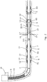
- pressurised fluid comprising proppants 25 is pumped down the well tubular structure in order to fracture the formation and stimulate the well, as shown in Fig. 2 .
- the pressurised fluid is supplied with proppants 25 which are smaller than the opening 19 but larger than the aperture 15, preventing the proppants 25 from entering the annular space 14 in the annular barrier 6.
- the proppants 25 are made of a material having a positive buoyancy in the fluid, and the proppants 25 therefore stay at the top of the well so that only the pressurised fluid is ejected through the opening 19 when the formation is fractured, as shown in Fig. 2 .
- a displacement means is arranged in the well for displacing the proppants 25 downwards in the well and, through the opening 19 and into the fracture, as shown in Fig. 2 . Due to the aperture 15 being smaller than the proppants 25, the proppants cannot flow into the annular barrier 6 but merely out through the intended opening 19 in the well tubular structure 4 and into the fractures to maintain the fractures open during a subsequent production.
- the proppants 25 do not accumulate in the area of the downhole tool 20, which would disturb the function of the tool, preventing the tool from being able to seal or even retract when the fracturing process has ended.
- the displacement means is an element 26a, such as a piston element, having an outer element diameter which is substantially equal to the inner diameter of the well tubular structure 4.
- the element 26a is pressed downwards towards the sliding sleeve 17 by pressurised fluid delivered from surface or the well head or the blow-out preventer at the top of the well, the fluid pressing onto the element to move the element acting as a piston.
- the displacement means is a fluid 26b having another density than the fracturing fluid and forming a fluid front pressing onto the proppants 25, thereby forcing the proppants towards the opening and out into the fractures just created.
- the proppants 25 have a substantially neutral or slightly positive buoyancy, allowing the proppants to easily flow along with the fracturing fluid and into the fractures without accumulating inside the well tubular structure 4 on top of the downhole tool 20, which would reduce the effect of the fracturing fluid, if not block the passage of fracturing fluid through the opening 19. Furthermore, the proppants 25 will not accumulate around the downhole tool 20 and prevent the function thereof.
- a valve 28 may be arranged in the aperture 15 of the annular barrier 6, as shown in Fig. 1 , and the valve may be a one-way valve so that fluid is allowed into the annular space 14 but unable to flow out of the space.
- the expandable sleeve 9 may be expanded by means of a compound which is arranged in the annular space 14 and is decomposable when subjected to heat-generating gas, which expands the sleeve 9.
- the downhole stimulation system 1 further comprises a third annular barrier 6, 6C arranged closer to the top than the first annular barrier 6, 6A and a fourth annular barrier 6D arranged further away from the top than the second annular barrier, and the inflatable device 22 is inflated between the second annular barrier 6, 6B and the fourth annular barrier6, 6D.
- the downhole tool 20 comprises an inflation pump 29 for inflating the inflatable device 22.
- the tool 20 further comprises a motor 31 for driving the inflation pump 29.
- the downhole tool of Fig. 3 is wireless and is powered by a power supply 58, such as a rechargeable battery.
- the keys 23 of the tool 20 are arranged at a second distance X t from the inflatable device 22 of the tool 20, and as shown in Fig. 3 , the second distance X t is larger than the first distance.
- the second distance X t may also be equal to the first distance in another embodiment.
- the keys are projectable keys 23 forming a piston part 32 which is slidable in a cavity 33 and projected by hydraulic fluid from the pump 29 through channels 34, compressing a spring 43, which ensures that the keys return to their retracted position when they are no longer required or if the power is cut off.
- the keys 23 have a profile 42 matching the profile in the sliding sleeve.
- the pump further inflates the inflatable device 22 through channels 35. When deflated, the fluid leaves the inflatable device 22 through other channels 36.
- the downhole tool 20 further comprises a detection unit 37 for detecting the sliding sleeve.
- the detection unit 37 comprises a tag identification means 38 for detecting the sliding sleeve.
- the tool 20 further comprises an activation means 39 for activating the inflatable device 22 to both inflate and deflate when e.g. the fracturing operation has ended.
- the activation means 39 comprises an activation sensor 40 adapted to cause the inflatable device 22 to deflate when a condition in the well changes, such as when a predetermined pressure is reached.
- the downhole tool 20 further comprises a detection sensor 27 for detecting a condition of the well and/or the sliding sleeve, so that the operation is terminated if the conditions vary too much from the expected conditions.
- the tool also comprises a communication unit 47 for loading information from a reservoir sensor if requested.
- the downhole tool 20 comprises a self-propelling means 48, such as a turbine or a propeller. So when descending, a battery in the tool is charged to be ready for use when the tool emerges at the top of the well again.
- the tool further comprises a fishing neck 49, making the tool easily retrievable from the well.
- the sliding sleeve 17 is a self-closing sleeve comprising a spring 51 for closing the sleeve.
- the spring in a cylinder housing 52 is compressed through the piston 53.
- the sliding sleeve 17 further comprises an identification tag 54 so that one sliding sleeve is recognisable from another.
- the well tubular structure 4 may comprise a plurality of sliding sleeves 17, each sliding sleeve having an identification tag 54.
- the annular barriers 6 may have at least one intermediate sleeve 55 between the expandable sleeve 9 and the tubular metal part 7, as shown in Fig. 5 .
- the expandable sleeve 9 comprises an opening for equalising the pressure between the reservoir and the inside of the annular barrier 6, in that the intermediate sleeve seals between the reservoir and the inside 5 of the well tubular structure 4.
- the pump pressurising the fluid for e.g. fracturing is submerged into the well tubular structure 4 and powered through a wireline 56 so that only part of the well tubular structure is pressurised.
- the downhole tool 20 may be wireless, as shown in Figs. 1-3 , or be powered through a wireline 56, as shown in Fig. 5 .
- the downhole tool 20 comprises a detection unit 37 for detecting the sliding sleeve and the aperture in order to determine the first distance X a (shown in Fig. 1 ).
- the detection unit 37 comprises a tag identification means 38 for detecting the profile of the sliding sleeve and the aperture of the annular barrier, and thus for detecting the first distance X a between the profile and the aperture.
- the keys 23 of the tool 20 are arranged at a second distance X t from the inflatable device 22 of the downhole tool, and the second distance is adjustable because the tool body comprises a length adjustable section 61 arranged between the key 23 and the inflatable device 22.
- the adjustable section 61 is adapted to adjust the second distance in relation to the detected first distance, and in Fig. 6 , the length adjustable section is a telescopic section. If the first distance between the profile of the sliding sleeve and the aperture is known before entering the well, the length of the tool does not need to be adjustable and the length adjustable section 61 can be dispensed with.
- the tool length, and thus the second distance is adjusted so as to fit the respective sliding sleeve.
- the downhole tool disengages the profile, causing the sliding sleeve to move into the closed position, and the tool moves further away from the top of the well. Then a second sliding sleeve is detected, the keys 23 of the tool are projected to engage the profile of the second sliding sleeve, and the inflatable device is inflated. Then, the inside of the well tubular structure is pressurised, moving the tool away from the top of the well and sliding the second sliding sleeve from a closed position to an open position and letting pressurised fluid from the inside of the well tubular structure in through the aperture of the adjacent annular barrier, e.g. a fourth annular barrier, equalising the pressure between the production zone and the annular space of the fourth annular barrier.
- a fourth annular barrier equalising the pressure between the production zone and the annular space of the fourth annular barrier.
- the proppants may comprise glass bubbles, cenospheres, microspheres and/or other similar materials having a structure which is adequate for functioning as a proppant while remaining generally buoyant in a fracturing fluid.
- the proppant may comprise a composite material, such as a syntactic foam, a porous material, such as an aerogel, a resin-coated aerogel, a resin-coated pumice, a ceramic foam or other type of foamed material, a crystalline material, such as zircon or other similar crystalline materials, or combinations thereof.
- a "porous material" can include particles having cylindrical and/or tubular structures (e.g. having an axial bore) through which fluid can pass.
- the porous material may be permeable to reservoir fluids, such as a filter material that permits passage of the fluid into and through the proppants, while the structure of the material enables the proppant to keep the fracture from decreasing.
- the proppants may further comprise, such as in the form of an outermost layer, a friction-reducing additive to facilitate transport of the proppants.
- fluid or well fluid any kind of fluid that may be present in oil or gas wells downhole, such as natural gas, oil, oil mud, crude oil, water, etc.
- gas is meant any kind of gas composition present in a well, completion, or open hole
- oil is meant any kind of oil composition, such as crude oil, an oil-containing fluid, etc.
- Gas, oil, and water fluids may thus all comprise other elements or substances than gas, oil, and/or water, respectively.
- a casing or a production casing is meant any kind of pipe, tubing, tubular, liner, string etc. used downhole in relation to oil or natural gas production.
- a downhole tractor can be used to push the tool all the way into position in the well.
- the downhole tractor may have projectable arms having wheels, wherein the wheels contact the inner surface of the casing for propelling the tractor and the tool forward in the casing.
- a downhole tractor is any kind of driving tool capable of pushing or pulling tools in a well downhole, such as a Well Tractor®.
Landscapes
- Geology (AREA)
- Life Sciences & Earth Sciences (AREA)
- Engineering & Computer Science (AREA)
- Mining & Mineral Resources (AREA)
- Physics & Mathematics (AREA)
- Geochemistry & Mineralogy (AREA)
- Fluid Mechanics (AREA)
- General Life Sciences & Earth Sciences (AREA)
- Environmental & Geological Engineering (AREA)
- Containers And Packaging Bodies Having A Special Means To Remove Contents (AREA)
- Geophysics (AREA)
- Details Of Reciprocating Pumps (AREA)
- Earth Drilling (AREA)
- Geophysics And Detection Of Objects (AREA)
- Pipe Accessories (AREA)
- Prostheses (AREA)
- Massaging Devices (AREA)
- Finger-Pressure Massage (AREA)
Claims (15)
- Système de stimulation de fond de trou (1) pour stimuler une production de fluide depuis un puits (2) présentant une partie supérieure (3), comprenant :- une structure tubulaire de puits (4) agencée dans un trou de forage dans une formation (24) et présentant un intérieur (5) et un diamètre intérieur (Di),- une première barrière annulaire (6, 6A) et une deuxième barrière annulaire (6, 6B) pour isoler une zone de production (101), ladite première barrière annulaire étant agencée le plus près de la partie supérieure du puits, chaque barrière annulaire comprenant :- une partie métallique tubulaire (7) pour un montage comme une partie de la structure tubulaire de puits, la partie métallique tubulaire présentant une face extérieure (8),- un manchon extensible (9) entourant la partie métallique tubulaire et présentant une face intérieure (10) faisant face à la partie métallique tubulaire et une face extérieure (11) faisant face à une paroi du trou de forage, chaque extrémité (12, 13) du manchon extensible étant raccordée à la partie métallique tubulaire,- une espace annulaire (14) entre la face intérieure du manchon extensible et la partie métallique tubulaire, et- une ouverture (15) agencée dans la partie métallique tubulaire pour laisser entrer du fluide dans l'espace, ladite ouverture présentant une taille d'ouverture prédéterminée,- un manchon coulissant (17) présentant au moins un profil (18) et étant agencé entre deux barrières annulaires et présentant une position fermée et une position ouverte dans laquelle un orifice (19) dans la structure tubulaire de puits fournit une communication fluidique entre l'intérieur de la structure tubulaire de puits et la zone de production, le profil du manchon coulissant étant positionné à une première distance (Xa) de l'ouverture de l'espace annulaire, l'orifice présentant une taille d'orifice prédéterminée,- un outil de fond de trou (20) pour amener le manchon coulissant depuis la position fermée à la position ouverte, comprenant :- un corps d'outil (21), et- un dispositif gonflable (22) adapté pour être gonflé dans la structure tubulaire de puits pour diviser la structure tubulaire de puits en une première partie (5A) et une seconde partie (5B), et- au moins une clé (23) entrant en prise avec le profil de sorte que lorsque le dispositif gonflable a été gonflé et la première partie de la structure tubulaire de puits a été pressurisée, l'outil soit déplacé en aval et la clé se déplace dans le profil, forçant le manchon coulissant depuis la position fermée vers le position ouverte, le dispositif gonflable étant agencé en aval de l'ouverture de la deuxième barrière annulaire de sorte que l'espace annulaire de la deuxième barrière annulaire soit en communication fluidique avec la première partie de la structure tubulaire de puits lorsque le dispositif gonflable est gonflé,dans lequel le système de stimulation de fond de trou comprend en outre une pompe (16) adaptée pour fournir du fluide pressurisé en bas de la structure tubulaire de puits afin de fissurer la formation et stimuler le puits,
caractérisé en ce que le fluide pressurisé est pourvu d'agents de soutènement (25) et les agents de soutènement présentant une taille qui est inférieure à celle de l'orifice et supérieure à l'ouverture, et en ce que
le système de stimulation de fond de trou comprend en outre un moyen de déplacement (26, 26a, 26b) pour déplacer les agents de soutènement vers le bas dans le puits vers l'extérieur à travers l'orifice et jusque dans la fissure. - Système de stimulation de fond de trou selon la revendication 1, dans lequel les agents de soutènement sont faits d'un matériau présentant une flottabilité positive dans le fluide.
- Système de stimulation de fond de trou selon la revendication 1 ou 2, dans lequel le moyen de déplacement est un élément (26a) présentant un diamètre d'élément extérieur qui est sensiblement égal au diamètre intérieur de la structure tubulaire de puits.
- Système de stimulation de fond de trou selon l'une quelconque des revendications 1 à 3, comprenant en outre une troisième barrière annulaire (6C) agencée plus près de la partie supérieure que la première barrière annulaire et une quatrième barrière annulaire (6D) agencée plus loin de la partie supérieure que la deuxième barrière annulaire, le dispositif gonflable étant gonflé entre la deuxième barrière annulaire et la quatrième barrière annulaire.
- Système de stimulation de fond de trou selon l'une quelconque des revendications 1 à 4, dans lequel le manchon coulissant est un manchon à fermeture automatique.
- Système de stimulation de fond de trou selon la revendication 5, dans lequel le manchon coulissant comprend un ressort pour fermer le manchon.
- Système de stimulation de fond de trou selon l'une quelconque des revendications précédentes, dans lequel une soupape est agencée dans l'ouverture d'au moins une des barrières annulaires.
- Système de stimulation de fond de trou selon l'une quelconque des revendications précédentes, dans lequel un diamètre du corps d'outil est inférieur à un diamètre intérieur de la structure tubulaire de puits, définissant un passage de fluide entre l'outil et la structure tubulaire de puits.
- Système de stimulation de fond de trou selon l'une quelconque des revendications précédentes, dans lequel l'outil comprend une pompe de gonflage pour gonfler le dispositif gonflable.
- Système de stimulation de fond de trou selon la revendication 9, dans lequel l'outil comprend un moteur pour entraîner la pompe de gonflage.
- Système de stimulation de fond de trou selon l'une quelconque des revendications précédentes, dans lequel le manchon coulissant et/ou l'ouverture comprend une étiquette d'identification (54).
- Système de stimulation de fond de trou selon l'une quelconque des revendications précédentes, dans lequel l'outil comprend une unité de détection (37) pour détecter le manchon coulissant et/ou l'ouverture.
- Système de stimulation de fond de trou selon la revendication 12, dans lequel l'unité de détection comprend un moyen d'identification d'étiquette (38) pour détecter le manchon coulissant et/ou l'ouverture.
- Système de stimulation de fond de trou selon l'une quelconque des revendications précédentes, dans lequel au moins une des barrières annulaires présente au moins un manchon intermédiaire (55) entre le manchon extensible et la partie tubulaire.
- Procédé de stimulation de fond de trou pour stimuler une production de fluide depuis un puits au moyen du système de stimulation de fond de trou selon l'une quelconque des revendications précédentes, comprenant les étapes consistant à :- détecter le manchon coulissant,- projeter les clés de l'outil,- faire entrer en prise le profil du manchon coulissant,- gonfler le dispositif gonflable,- pressuriser l'intérieur de la structure tubulaire de puits,- déplacer l'outil loin de la partie supérieure du puits, en faisant coulisser le manchon d'une position fermée vers une position ouverte,- laisser entrer du fluide pressurisé depuis l'intérieur de la structure tubulaire de puits à travers l'ouverture de la deuxième barrière annulaire pour égaliser la pression entre la zone de production et l'espace annulaire de la deuxième barrière annulaire,- laisser sortir le fluide à travers l'orifice pour fissurer la formation,- fournir des agents de soutènement présentant une taille qui est inférieure à celle de l'orifice et supérieure à l'ouverture au fluide pressurisé, et- déplacer les agents de soutènement hors de l'orifice vers la fissure tout en égalisant la pression entre la zone de production et l'espace annulaire de la deuxième barrière annulaire et tout en empêchant les agents de soutènement d'entrer dans l'ouverture de la barrière annulaire.
Applications Claiming Priority (3)
| Application Number | Priority Date | Filing Date | Title |
|---|---|---|---|
| EP14173461.6A EP2960427A1 (fr) | 2014-06-23 | 2014-06-23 | Système de stimulation de fond de trou |
| EP15160034 | 2015-03-20 | ||
| PCT/EP2015/063940 WO2015197532A1 (fr) | 2014-06-23 | 2015-06-22 | Système de stimulation de fond de trou |
Publications (2)
| Publication Number | Publication Date |
|---|---|
| EP3158162A1 EP3158162A1 (fr) | 2017-04-26 |
| EP3158162B1 true EP3158162B1 (fr) | 2020-08-26 |
Family
ID=53483814
Family Applications (1)
| Application Number | Title | Priority Date | Filing Date |
|---|---|---|---|
| EP15731038.4A Not-in-force EP3158162B1 (fr) | 2014-06-23 | 2015-06-22 | Système de stimulation de fond de trou |
Country Status (9)
| Country | Link |
|---|---|
| US (1) | US10458219B2 (fr) |
| EP (1) | EP3158162B1 (fr) |
| CN (1) | CN106460477B (fr) |
| AU (1) | AU2015279426B2 (fr) |
| CA (1) | CA2951976A1 (fr) |
| DK (1) | DK3158162T3 (fr) |
| MX (1) | MX2016016292A (fr) |
| RU (1) | RU2682282C2 (fr) |
| WO (1) | WO2015197532A1 (fr) |
Families Citing this family (11)
| Publication number | Priority date | Publication date | Assignee | Title |
|---|---|---|---|---|
| WO2016178005A1 (fr) | 2015-05-01 | 2016-11-10 | Churchill Drilling Tools Limited | Étanchéité et actionnement en profondeur de forage |
| EP3205812A1 (fr) * | 2016-02-10 | 2017-08-16 | Welltec A/S | Dispositif de fond de trou et système de fond de trou |
| EP3258057A1 (fr) * | 2016-06-17 | 2017-12-20 | Welltec A/S | Procédé de fracturation utilisant un fluide in situ |
| GB2559555B (en) * | 2017-02-08 | 2019-11-27 | Total E&P Danmark As | Downhole operations |
| WO2019067012A1 (fr) * | 2017-09-29 | 2019-04-04 | Comitt Well Solutions Us Holding Inc. | Procédés et systèmes pour déplacer un manchon coulissant sur la base d'une pression interne |
| CN110331969B (zh) * | 2019-06-14 | 2021-04-20 | 弗润联科(北京)石油科技有限公司 | 跨隔式试油测试及重复压裂工具系统 |
| US11788394B2 (en) * | 2021-07-15 | 2023-10-17 | Eden Geopower, Inc. | Systems and methods for deployment of electric-based fracturing tools in vertical wells |
| US12297720B2 (en) * | 2021-11-29 | 2025-05-13 | Saudi Arabian Oil Company | Downhole perforating tool systems and methods |
| US11851974B1 (en) * | 2022-08-26 | 2023-12-26 | Saudi Arabian Oil Company | Resettable packer system for pumping operations |
| US20250146397A1 (en) * | 2023-11-08 | 2025-05-08 | Agog Energy Inc. | Enhanced well extraction tool |
| US12486733B1 (en) * | 2024-05-31 | 2025-12-02 | Schlumberger Technology Corporation | Systems and methods for surface supervision of a downhole tool |
Family Cites Families (16)
| Publication number | Priority date | Publication date | Assignee | Title |
|---|---|---|---|---|
| US4421167A (en) * | 1980-11-05 | 1983-12-20 | Exxon Production Research Co. | Method of controlling displacement of propping agent in fracturing treatments |
| US4886117A (en) * | 1986-10-24 | 1989-12-12 | Schlumberger Technology Corporation | Inflatable well packers |
| US5417285A (en) * | 1992-08-07 | 1995-05-23 | Baker Hughes Incorporated | Method and apparatus for sealing and transferring force in a wellbore |
| CN100347404C (zh) * | 2003-01-13 | 2007-11-07 | 施蓝姆伯格技术公司 | 用于处理地层的方法和设备 |
| US6998557B2 (en) * | 2003-08-29 | 2006-02-14 | Premark Feg L.L.C. | Power driven food machine and related multi-action switch assembly |
| US8297367B2 (en) | 2010-05-21 | 2012-10-30 | Schlumberger Technology Corporation | Mechanism for activating a plurality of downhole devices |
| CA2811598A1 (fr) * | 2010-09-21 | 2012-03-29 | Oxane Materials, Inc. | Element de soutenement leger ayant une resistance mecanique amelioree et ses procedes de production |
| CN102071900B (zh) * | 2010-11-23 | 2013-04-24 | 中国石油天然气股份有限公司 | 自定压扩张式裸眼封隔器 |
| EP2484862B1 (fr) | 2011-02-07 | 2018-04-11 | Weatherford Technology Holdings, LLC | Manche d'indexation pour fracturation multi-niveaux en une seule manoeuvre |
| US8720561B2 (en) * | 2011-04-12 | 2014-05-13 | Saudi Arabian Oil Company | Sliding stage cementing tool and method |
| RU2473790C1 (ru) | 2011-08-22 | 2013-01-27 | Общество с ограниченной ответственностью "Торговый дом "Нефтекамский машиностроительный завод" | Система эксплуатации скважин погружным электронасосом посредством пакеров с кабельным вводом |
| EP2708694A1 (fr) * | 2012-09-14 | 2014-03-19 | Welltec A/S | Dispositif de chute |
| EP2728108A1 (fr) * | 2012-10-31 | 2014-05-07 | Welltec A/S | Système de fond de trou et dispositif de chute |
| RU2515651C1 (ru) | 2013-05-20 | 2014-05-20 | Открытое акционерное общество "Татнефть" им. В.Д. Шашина | Способ многократного гидравлического разрыва пласта в горизонтальном стволе скважины |
| CN103277079B (zh) * | 2013-06-04 | 2015-12-09 | 中国海洋石油总公司 | 一种水平井压裂完井的管柱及其压裂施工方法 |
| US20150021021A1 (en) * | 2013-07-17 | 2015-01-22 | Halliburton Energy Services, Inc. | Multiple-Interval Wellbore Stimulation System and Method |
-
2015
- 2015-06-22 AU AU2015279426A patent/AU2015279426B2/en not_active Ceased
- 2015-06-22 EP EP15731038.4A patent/EP3158162B1/fr not_active Not-in-force
- 2015-06-22 US US15/321,382 patent/US10458219B2/en not_active Expired - Fee Related
- 2015-06-22 RU RU2017100019A patent/RU2682282C2/ru active
- 2015-06-22 WO PCT/EP2015/063940 patent/WO2015197532A1/fr not_active Ceased
- 2015-06-22 MX MX2016016292A patent/MX2016016292A/es unknown
- 2015-06-22 CA CA2951976A patent/CA2951976A1/fr not_active Abandoned
- 2015-06-22 CN CN201580030580.1A patent/CN106460477B/zh not_active Expired - Fee Related
- 2015-06-22 DK DK15731038.4T patent/DK3158162T3/da active
Non-Patent Citations (1)
| Title |
|---|
| None * |
Also Published As
| Publication number | Publication date |
|---|---|
| US10458219B2 (en) | 2019-10-29 |
| EP3158162A1 (fr) | 2017-04-26 |
| WO2015197532A1 (fr) | 2015-12-30 |
| AU2015279426A1 (en) | 2017-02-02 |
| RU2017100019A3 (fr) | 2019-01-14 |
| CN106460477A (zh) | 2017-02-22 |
| CA2951976A1 (fr) | 2015-12-30 |
| US20170145801A1 (en) | 2017-05-25 |
| CN106460477B (zh) | 2020-12-04 |
| DK3158162T3 (da) | 2020-11-30 |
| RU2682282C2 (ru) | 2019-03-18 |
| AU2015279426B2 (en) | 2017-09-14 |
| MX2016016292A (es) | 2017-03-31 |
| RU2017100019A (ru) | 2018-07-23 |
Similar Documents
| Publication | Publication Date | Title |
|---|---|---|
| US10458219B2 (en) | Downhole stimulation system | |
| EP3743593B1 (fr) | Outil d'intervention de câble de fond de trou | |
| AU2018285312B2 (en) | Downhole patch setting tool | |
| US20140374100A1 (en) | Punching tool | |
| EP2728108A1 (fr) | Système de fond de trou et dispositif de chute | |
| AU2013314271B2 (en) | Drop device | |
| US20160177658A1 (en) | Packer apparatuses | |
| AU2019258528B2 (en) | Workover tool string | |
| CN104024565A (zh) | 与钻头接头一起使用的膨胀式封隔器元件 | |
| US20170350194A1 (en) | Wellbore tool reamer assembly | |
| EP3908733B1 (fr) | Procédé de fond de puits | |
| EP2960427A1 (fr) | Système de stimulation de fond de trou | |
| US20180258733A1 (en) | Method and System to Protect Legacy Production and to Mitigate the Risk of an Uncontrolled Release from Oil and Gas Wells | |
| EP3258057A1 (fr) | Procédé de fracturation utilisant un fluide in situ | |
| WO2016202834A1 (fr) | Procédé de rhabillage et système de complétion rhabillé |
Legal Events
| Date | Code | Title | Description |
|---|---|---|---|
| STAA | Information on the status of an ep patent application or granted ep patent |
Free format text: STATUS: THE INTERNATIONAL PUBLICATION HAS BEEN MADE |
|
| PUAI | Public reference made under article 153(3) epc to a published international application that has entered the european phase |
Free format text: ORIGINAL CODE: 0009012 |
|
| STAA | Information on the status of an ep patent application or granted ep patent |
Free format text: STATUS: REQUEST FOR EXAMINATION WAS MADE |
|
| 17P | Request for examination filed |
Effective date: 20170113 |
|
| AK | Designated contracting states |
Kind code of ref document: A1 Designated state(s): AL AT BE BG CH CY CZ DE DK EE ES FI FR GB GR HR HU IE IS IT LI LT LU LV MC MK MT NL NO PL PT RO RS SE SI SK SM TR |
|
| AX | Request for extension of the european patent |
Extension state: BA ME |
|
| DAV | Request for validation of the european patent (deleted) | ||
| DAX | Request for extension of the european patent (deleted) | ||
| STAA | Information on the status of an ep patent application or granted ep patent |
Free format text: STATUS: EXAMINATION IS IN PROGRESS |
|
| 17Q | First examination report despatched |
Effective date: 20180308 |
|
| RAP1 | Party data changed (applicant data changed or rights of an application transferred) |
Owner name: WELLTEC OILFIELD SOLUTIONS AG |
|
| GRAP | Despatch of communication of intention to grant a patent |
Free format text: ORIGINAL CODE: EPIDOSNIGR1 |
|
| STAA | Information on the status of an ep patent application or granted ep patent |
Free format text: STATUS: GRANT OF PATENT IS INTENDED |
|
| INTG | Intention to grant announced |
Effective date: 20191125 |
|
| GRAS | Grant fee paid |
Free format text: ORIGINAL CODE: EPIDOSNIGR3 |
|
| GRAJ | Information related to disapproval of communication of intention to grant by the applicant or resumption of examination proceedings by the epo deleted |
Free format text: ORIGINAL CODE: EPIDOSDIGR1 |
|
| GRAL | Information related to payment of fee for publishing/printing deleted |
Free format text: ORIGINAL CODE: EPIDOSDIGR3 |
|
| STAA | Information on the status of an ep patent application or granted ep patent |
Free format text: STATUS: EXAMINATION IS IN PROGRESS |
|
| GRAP | Despatch of communication of intention to grant a patent |
Free format text: ORIGINAL CODE: EPIDOSNIGR1 |
|
| STAA | Information on the status of an ep patent application or granted ep patent |
Free format text: STATUS: GRANT OF PATENT IS INTENDED |
|
| RAP1 | Party data changed (applicant data changed or rights of an application transferred) |
Owner name: WELLTEC OILFIELD SOLUTIONS AG |
|
| INTG | Intention to grant announced |
Effective date: 20200403 |
|
| GRAS | Grant fee paid |
Free format text: ORIGINAL CODE: EPIDOSNIGR3 |
|
| GRAA | (expected) grant |
Free format text: ORIGINAL CODE: 0009210 |
|
| STAA | Information on the status of an ep patent application or granted ep patent |
Free format text: STATUS: THE PATENT HAS BEEN GRANTED |
|
| AK | Designated contracting states |
Kind code of ref document: B1 Designated state(s): AL AT BE BG CH CY CZ DE DK EE ES FI FR GB GR HR HU IE IS IT LI LT LU LV MC MK MT NL NO PL PT RO RS SE SI SK SM TR |
|
| REG | Reference to a national code |
Ref country code: GB Ref legal event code: FG4D |
|
| REG | Reference to a national code |
Ref country code: CH Ref legal event code: EP |
|
| REG | Reference to a national code |
Ref country code: DE Ref legal event code: R096 Ref document number: 602015058009 Country of ref document: DE |
|
| REG | Reference to a national code |
Ref country code: AT Ref legal event code: REF Ref document number: 1306539 Country of ref document: AT Kind code of ref document: T Effective date: 20200915 |
|
| REG | Reference to a national code |
Ref country code: IE Ref legal event code: FG4D |
|
| REG | Reference to a national code |
Ref country code: NL Ref legal event code: FP |
|
| REG | Reference to a national code |
Ref country code: DK Ref legal event code: T3 Effective date: 20201123 |
|
| REG | Reference to a national code |
Ref country code: NO Ref legal event code: T2 Effective date: 20200826 |
|
| REG | Reference to a national code |
Ref country code: LT Ref legal event code: MG4D |
|
| PG25 | Lapsed in a contracting state [announced via postgrant information from national office to epo] |
Ref country code: HR Free format text: LAPSE BECAUSE OF FAILURE TO SUBMIT A TRANSLATION OF THE DESCRIPTION OR TO PAY THE FEE WITHIN THE PRESCRIBED TIME-LIMIT Effective date: 20200826 Ref country code: BG Free format text: LAPSE BECAUSE OF FAILURE TO SUBMIT A TRANSLATION OF THE DESCRIPTION OR TO PAY THE FEE WITHIN THE PRESCRIBED TIME-LIMIT Effective date: 20201126 Ref country code: LT Free format text: LAPSE BECAUSE OF FAILURE TO SUBMIT A TRANSLATION OF THE DESCRIPTION OR TO PAY THE FEE WITHIN THE PRESCRIBED TIME-LIMIT Effective date: 20200826 Ref country code: PT Free format text: LAPSE BECAUSE OF FAILURE TO SUBMIT A TRANSLATION OF THE DESCRIPTION OR TO PAY THE FEE WITHIN THE PRESCRIBED TIME-LIMIT Effective date: 20201228 Ref country code: SE Free format text: LAPSE BECAUSE OF FAILURE TO SUBMIT A TRANSLATION OF THE DESCRIPTION OR TO PAY THE FEE WITHIN THE PRESCRIBED TIME-LIMIT Effective date: 20200826 Ref country code: GR Free format text: LAPSE BECAUSE OF FAILURE TO SUBMIT A TRANSLATION OF THE DESCRIPTION OR TO PAY THE FEE WITHIN THE PRESCRIBED TIME-LIMIT Effective date: 20201127 Ref country code: FI Free format text: LAPSE BECAUSE OF FAILURE TO SUBMIT A TRANSLATION OF THE DESCRIPTION OR TO PAY THE FEE WITHIN THE PRESCRIBED TIME-LIMIT Effective date: 20200826 |
|
| REG | Reference to a national code |
Ref country code: AT Ref legal event code: MK05 Ref document number: 1306539 Country of ref document: AT Kind code of ref document: T Effective date: 20200826 |
|
| PG25 | Lapsed in a contracting state [announced via postgrant information from national office to epo] |
Ref country code: PL Free format text: LAPSE BECAUSE OF FAILURE TO SUBMIT A TRANSLATION OF THE DESCRIPTION OR TO PAY THE FEE WITHIN THE PRESCRIBED TIME-LIMIT Effective date: 20200826 Ref country code: LV Free format text: LAPSE BECAUSE OF FAILURE TO SUBMIT A TRANSLATION OF THE DESCRIPTION OR TO PAY THE FEE WITHIN THE PRESCRIBED TIME-LIMIT Effective date: 20200826 Ref country code: RS Free format text: LAPSE BECAUSE OF FAILURE TO SUBMIT A TRANSLATION OF THE DESCRIPTION OR TO PAY THE FEE WITHIN THE PRESCRIBED TIME-LIMIT Effective date: 20200826 Ref country code: IS Free format text: LAPSE BECAUSE OF FAILURE TO SUBMIT A TRANSLATION OF THE DESCRIPTION OR TO PAY THE FEE WITHIN THE PRESCRIBED TIME-LIMIT Effective date: 20201226 |
|
| PG25 | Lapsed in a contracting state [announced via postgrant information from national office to epo] |
Ref country code: RO Free format text: LAPSE BECAUSE OF FAILURE TO SUBMIT A TRANSLATION OF THE DESCRIPTION OR TO PAY THE FEE WITHIN THE PRESCRIBED TIME-LIMIT Effective date: 20200826 Ref country code: SM Free format text: LAPSE BECAUSE OF FAILURE TO SUBMIT A TRANSLATION OF THE DESCRIPTION OR TO PAY THE FEE WITHIN THE PRESCRIBED TIME-LIMIT Effective date: 20200826 Ref country code: EE Free format text: LAPSE BECAUSE OF FAILURE TO SUBMIT A TRANSLATION OF THE DESCRIPTION OR TO PAY THE FEE WITHIN THE PRESCRIBED TIME-LIMIT Effective date: 20200826 Ref country code: CZ Free format text: LAPSE BECAUSE OF FAILURE TO SUBMIT A TRANSLATION OF THE DESCRIPTION OR TO PAY THE FEE WITHIN THE PRESCRIBED TIME-LIMIT Effective date: 20200826 |
|
| REG | Reference to a national code |
Ref country code: DE Ref legal event code: R097 Ref document number: 602015058009 Country of ref document: DE |
|
| PG25 | Lapsed in a contracting state [announced via postgrant information from national office to epo] |
Ref country code: AT Free format text: LAPSE BECAUSE OF FAILURE TO SUBMIT A TRANSLATION OF THE DESCRIPTION OR TO PAY THE FEE WITHIN THE PRESCRIBED TIME-LIMIT Effective date: 20200826 Ref country code: AL Free format text: LAPSE BECAUSE OF FAILURE TO SUBMIT A TRANSLATION OF THE DESCRIPTION OR TO PAY THE FEE WITHIN THE PRESCRIBED TIME-LIMIT Effective date: 20200826 Ref country code: ES Free format text: LAPSE BECAUSE OF FAILURE TO SUBMIT A TRANSLATION OF THE DESCRIPTION OR TO PAY THE FEE WITHIN THE PRESCRIBED TIME-LIMIT Effective date: 20200826 |
|
| PG25 | Lapsed in a contracting state [announced via postgrant information from national office to epo] |
Ref country code: SK Free format text: LAPSE BECAUSE OF FAILURE TO SUBMIT A TRANSLATION OF THE DESCRIPTION OR TO PAY THE FEE WITHIN THE PRESCRIBED TIME-LIMIT Effective date: 20200826 |
|
| PLBE | No opposition filed within time limit |
Free format text: ORIGINAL CODE: 0009261 |
|
| STAA | Information on the status of an ep patent application or granted ep patent |
Free format text: STATUS: NO OPPOSITION FILED WITHIN TIME LIMIT |
|
| PG25 | Lapsed in a contracting state [announced via postgrant information from national office to epo] |
Ref country code: IT Free format text: LAPSE BECAUSE OF FAILURE TO SUBMIT A TRANSLATION OF THE DESCRIPTION OR TO PAY THE FEE WITHIN THE PRESCRIBED TIME-LIMIT Effective date: 20200826 |
|
| 26N | No opposition filed |
Effective date: 20210527 |
|
| PG25 | Lapsed in a contracting state [announced via postgrant information from national office to epo] |
Ref country code: SI Free format text: LAPSE BECAUSE OF FAILURE TO SUBMIT A TRANSLATION OF THE DESCRIPTION OR TO PAY THE FEE WITHIN THE PRESCRIBED TIME-LIMIT Effective date: 20200826 |
|
| REG | Reference to a national code |
Ref country code: DE Ref legal event code: R119 Ref document number: 602015058009 Country of ref document: DE |
|
| REG | Reference to a national code |
Ref country code: NO Ref legal event code: MMEP Ref country code: DK Ref legal event code: EBP Effective date: 20210630 |
|
| PG25 | Lapsed in a contracting state [announced via postgrant information from national office to epo] |
Ref country code: MC Free format text: LAPSE BECAUSE OF FAILURE TO SUBMIT A TRANSLATION OF THE DESCRIPTION OR TO PAY THE FEE WITHIN THE PRESCRIBED TIME-LIMIT Effective date: 20200826 |
|
| REG | Reference to a national code |
Ref country code: CH Ref legal event code: PL |
|
| REG | Reference to a national code |
Ref country code: NL Ref legal event code: MM Effective date: 20210701 |
|
| GBPC | Gb: european patent ceased through non-payment of renewal fee |
Effective date: 20210622 |
|
| REG | Reference to a national code |
Ref country code: BE Ref legal event code: MM Effective date: 20210630 |
|
| PG25 | Lapsed in a contracting state [announced via postgrant information from national office to epo] |
Ref country code: LU Free format text: LAPSE BECAUSE OF NON-PAYMENT OF DUE FEES Effective date: 20210622 |
|
| PG25 | Lapsed in a contracting state [announced via postgrant information from national office to epo] |
Ref country code: LI Free format text: LAPSE BECAUSE OF NON-PAYMENT OF DUE FEES Effective date: 20210630 Ref country code: IE Free format text: LAPSE BECAUSE OF NON-PAYMENT OF DUE FEES Effective date: 20210622 Ref country code: GB Free format text: LAPSE BECAUSE OF NON-PAYMENT OF DUE FEES Effective date: 20210622 Ref country code: DE Free format text: LAPSE BECAUSE OF NON-PAYMENT OF DUE FEES Effective date: 20220101 Ref country code: CH Free format text: LAPSE BECAUSE OF NON-PAYMENT OF DUE FEES Effective date: 20210630 |
|
| PG25 | Lapsed in a contracting state [announced via postgrant information from national office to epo] |
Ref country code: NO Free format text: LAPSE BECAUSE OF NON-PAYMENT OF DUE FEES Effective date: 20210630 Ref country code: NL Free format text: LAPSE BECAUSE OF NON-PAYMENT OF DUE FEES Effective date: 20210701 Ref country code: FR Free format text: LAPSE BECAUSE OF NON-PAYMENT OF DUE FEES Effective date: 20210630 |
|
| PG25 | Lapsed in a contracting state [announced via postgrant information from national office to epo] |
Ref country code: DK Free format text: LAPSE BECAUSE OF NON-PAYMENT OF DUE FEES Effective date: 20210630 Ref country code: BE Free format text: LAPSE BECAUSE OF NON-PAYMENT OF DUE FEES Effective date: 20210630 |
|
| PG25 | Lapsed in a contracting state [announced via postgrant information from national office to epo] |
Ref country code: HU Free format text: LAPSE BECAUSE OF FAILURE TO SUBMIT A TRANSLATION OF THE DESCRIPTION OR TO PAY THE FEE WITHIN THE PRESCRIBED TIME-LIMIT; INVALID AB INITIO Effective date: 20150622 |
|
| PG25 | Lapsed in a contracting state [announced via postgrant information from national office to epo] |
Ref country code: CY Free format text: LAPSE BECAUSE OF FAILURE TO SUBMIT A TRANSLATION OF THE DESCRIPTION OR TO PAY THE FEE WITHIN THE PRESCRIBED TIME-LIMIT Effective date: 20200826 |
|
| PG25 | Lapsed in a contracting state [announced via postgrant information from national office to epo] |
Ref country code: MK Free format text: LAPSE BECAUSE OF FAILURE TO SUBMIT A TRANSLATION OF THE DESCRIPTION OR TO PAY THE FEE WITHIN THE PRESCRIBED TIME-LIMIT Effective date: 20200826 |
|
| PG25 | Lapsed in a contracting state [announced via postgrant information from national office to epo] |
Ref country code: TR Free format text: LAPSE BECAUSE OF FAILURE TO SUBMIT A TRANSLATION OF THE DESCRIPTION OR TO PAY THE FEE WITHIN THE PRESCRIBED TIME-LIMIT Effective date: 20200826 |
|
| PG25 | Lapsed in a contracting state [announced via postgrant information from national office to epo] |
Ref country code: MT Free format text: LAPSE BECAUSE OF FAILURE TO SUBMIT A TRANSLATION OF THE DESCRIPTION OR TO PAY THE FEE WITHIN THE PRESCRIBED TIME-LIMIT Effective date: 20200826 |