EP3158185B1 - Kraftstoff-hochdruckpumpe für ein kraftstoffsystem für eine brennkraftmaschine - Google Patents
Kraftstoff-hochdruckpumpe für ein kraftstoffsystem für eine brennkraftmaschine Download PDFInfo
- Publication number
- EP3158185B1 EP3158185B1 EP15720091.6A EP15720091A EP3158185B1 EP 3158185 B1 EP3158185 B1 EP 3158185B1 EP 15720091 A EP15720091 A EP 15720091A EP 3158185 B1 EP3158185 B1 EP 3158185B1
- Authority
- EP
- European Patent Office
- Prior art keywords
- closing
- valve
- fuel pump
- pressure
- pressure fuel
- Prior art date
- Legal status (The legal status is an assumption and is not a legal conclusion. Google has not performed a legal analysis and makes no representation as to the accuracy of the status listed.)
- Active
Links
Images
Classifications
-
- F—MECHANICAL ENGINEERING; LIGHTING; HEATING; WEAPONS; BLASTING
- F02—COMBUSTION ENGINES; HOT-GAS OR COMBUSTION-PRODUCT ENGINE PLANTS
- F02M—SUPPLYING COMBUSTION ENGINES IN GENERAL WITH COMBUSTIBLE MIXTURES OR CONSTITUENTS THEREOF
- F02M63/00—Other fuel-injection apparatus having pertinent characteristics not provided for in groups F02M39/00 - F02M57/00 or F02M67/00; Details, component parts, or accessories of fuel-injection apparatus, not provided for in, or of interest apart from, the apparatus of groups F02M39/00 - F02M61/00 or F02M67/00; Combination of fuel pump with other devices, e.g. lubricating oil pump
- F02M63/02—Fuel-injection apparatus having several injectors fed by a common pumping element, or having several pumping elements feeding a common injector; Fuel-injection apparatus having provisions for cutting-out pumps, pumping elements, or injectors; Fuel-injection apparatus having provisions for variably interconnecting pumping elements and injectors alternatively
- F02M63/0205—Fuel-injection apparatus having several injectors fed by a common pumping element, or having several pumping elements feeding a common injector; Fuel-injection apparatus having provisions for cutting-out pumps, pumping elements, or injectors; Fuel-injection apparatus having provisions for variably interconnecting pumping elements and injectors alternatively for cutting-out pumps or injectors in case of abnormal operation of the engine or the injection apparatus, e.g. over-speed, break-down of fuel pumps or injectors ; for cutting-out pumps for stopping the engine
- F02M63/0215—Fuel-injection apparatus having several injectors fed by a common pumping element, or having several pumping elements feeding a common injector; Fuel-injection apparatus having provisions for cutting-out pumps, pumping elements, or injectors; Fuel-injection apparatus having provisions for variably interconnecting pumping elements and injectors alternatively for cutting-out pumps or injectors in case of abnormal operation of the engine or the injection apparatus, e.g. over-speed, break-down of fuel pumps or injectors ; for cutting-out pumps for stopping the engine by draining or closing fuel conduits
-
- F—MECHANICAL ENGINEERING; LIGHTING; HEATING; WEAPONS; BLASTING
- F02—COMBUSTION ENGINES; HOT-GAS OR COMBUSTION-PRODUCT ENGINE PLANTS
- F02M—SUPPLYING COMBUSTION ENGINES IN GENERAL WITH COMBUSTIBLE MIXTURES OR CONSTITUENTS THEREOF
- F02M55/00—Fuel-injection apparatus characterised by their fuel conduits or their venting means; Arrangements of conduits between fuel tank and pump F02M37/00
- F02M55/02—Conduits between injection pumps and injectors, e.g. conduits between pump and common-rail or conduits between common-rail and injectors
-
- F—MECHANICAL ENGINEERING; LIGHTING; HEATING; WEAPONS; BLASTING
- F02—COMBUSTION ENGINES; HOT-GAS OR COMBUSTION-PRODUCT ENGINE PLANTS
- F02M—SUPPLYING COMBUSTION ENGINES IN GENERAL WITH COMBUSTIBLE MIXTURES OR CONSTITUENTS THEREOF
- F02M59/00—Pumps specially adapted for fuel-injection and not provided for in groups F02M39/00 -F02M57/00, e.g. rotary cylinder-block type of pumps
- F02M59/44—Details, components parts, or accessories not provided for in, or of interest apart from, the apparatus of groups F02M59/02 - F02M59/42; Pumps having transducers, e.g. to measure displacement of pump rack or piston
- F02M59/46—Valves
- F02M59/462—Delivery valves
-
- F—MECHANICAL ENGINEERING; LIGHTING; HEATING; WEAPONS; BLASTING
- F02—COMBUSTION ENGINES; HOT-GAS OR COMBUSTION-PRODUCT ENGINE PLANTS
- F02M—SUPPLYING COMBUSTION ENGINES IN GENERAL WITH COMBUSTIBLE MIXTURES OR CONSTITUENTS THEREOF
- F02M63/00—Other fuel-injection apparatus having pertinent characteristics not provided for in groups F02M39/00 - F02M57/00 or F02M67/00; Details, component parts, or accessories of fuel-injection apparatus, not provided for in, or of interest apart from, the apparatus of groups F02M39/00 - F02M61/00 or F02M67/00; Combination of fuel pump with other devices, e.g. lubricating oil pump
- F02M63/0012—Valves
- F02M63/0031—Valves characterized by the type of valves, e.g. special valve member details, valve seat details, valve housing details
- F02M63/0033—Lift valves, i.e. having a valve member that moves perpendicularly to the plane of the valve seat
- F02M63/0036—Lift valves, i.e. having a valve member that moves perpendicularly to the plane of the valve seat with spherical or partly spherical shaped valve member ends
-
- F—MECHANICAL ENGINEERING; LIGHTING; HEATING; WEAPONS; BLASTING
- F02—COMBUSTION ENGINES; HOT-GAS OR COMBUSTION-PRODUCT ENGINE PLANTS
- F02M—SUPPLYING COMBUSTION ENGINES IN GENERAL WITH COMBUSTIBLE MIXTURES OR CONSTITUENTS THEREOF
- F02M63/00—Other fuel-injection apparatus having pertinent characteristics not provided for in groups F02M39/00 - F02M57/00 or F02M67/00; Details, component parts, or accessories of fuel-injection apparatus, not provided for in, or of interest apart from, the apparatus of groups F02M39/00 - F02M61/00 or F02M67/00; Combination of fuel pump with other devices, e.g. lubricating oil pump
- F02M63/0012—Valves
- F02M63/0031—Valves characterized by the type of valves, e.g. special valve member details, valve seat details, valve housing details
- F02M63/0054—Check valves
-
- F—MECHANICAL ENGINEERING; LIGHTING; HEATING; WEAPONS; BLASTING
- F02—COMBUSTION ENGINES; HOT-GAS OR COMBUSTION-PRODUCT ENGINE PLANTS
- F02M—SUPPLYING COMBUSTION ENGINES IN GENERAL WITH COMBUSTIBLE MIXTURES OR CONSTITUENTS THEREOF
- F02M63/00—Other fuel-injection apparatus having pertinent characteristics not provided for in groups F02M39/00 - F02M57/00 or F02M67/00; Details, component parts, or accessories of fuel-injection apparatus, not provided for in, or of interest apart from, the apparatus of groups F02M39/00 - F02M61/00 or F02M67/00; Combination of fuel pump with other devices, e.g. lubricating oil pump
- F02M63/0012—Valves
- F02M63/007—Details not provided for in, or of interest apart from, the apparatus of the groups F02M63/0014 - F02M63/0059
- F02M63/0075—Stop members in valves, e.g. plates or disks limiting the movement of armature, valve or spring
Definitions
- a high-pressure fuel pump can deliver fuel from a low-pressure region, for example downstream of a prefeed pump, into a high-pressure region, in particular into a high-pressure reservoir (rail).
- high-pressure fuel pumps frequently have a pressure-limiting valve which can limit a fuel pressure in the high-pressure region to a predefinable maximum value.
- operation of the high-pressure fuel pump can be improved and possible damages of the fuel system can be prevented.
- the DE 197 10 891 A1 discloses a fuel injection pump.
- a closing body is arranged between the closing element and the valve spring, which cooperates with the stop body and which preferably - but not necessarily - is made massive.
- a guide portion of the closing body and / or a guide portion of the stopper body are designed peg-shaped / is, wherein an outer diameter of the respective guide portion is smaller than an inner diameter of the valve spring.
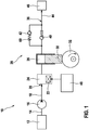
- the high-pressure fuel pump 28 is designed as a piston pump, wherein a piston 30 can be moved vertically by means of a cam 32 in the drawing.
- Hydraulically between the delivery chamber 26 and an outlet 36 of the high-pressure fuel pump 28 is a in the FIG. 1 arranged as a spring-loaded check valve drawn outlet valve 40 and a likewise drawn as a spring-loaded check valve pressure relief valve 42.
- the outlet 36 is connected to a high-pressure line 44 and via this to a high-pressure accumulator 46 ("common rail").
- the exhaust valve 40 may open to the outlet 36 and the pressure relief valve 42 to the pumping chamber 26 out.
- the electromagnetic actuator 22 is controlled by a control and / or regulating device 48. Deviating from the presentation of FIG. 1 can one in the FIG. 1 left terminal of the pressure limiting valve 42 alternatively instead of the outlet (without reference numeral) of the high-pressure fuel pump 28 may also be connected to the delivery chamber 26 or any other element upstream of the high-pressure fuel pump 28.
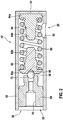
- FIG. 2 shows a longitudinal section through the pressure relief valve 42 of the high-pressure fuel pump 28 of FIG. 1 ,
- the pressure relief valve 42 is hydraulically disposed between the outlet 36 and an upstream of the outlet 36 portion of the high-pressure fuel pump 28 and can open to the upstream region.
- the pressure relief valve 42 and its elements described in more detail below are designed essentially rotationally symmetrical.
- the pressure limiting valve 42 comprises a housing 50 which is designed essentially as a cylindrical sleeve. At one in the FIG. 1 left end face, the housing 50 has an axial first opening 52, wherein a radius of the opening 52 corresponds to an inner radius of the cylindrical sleeve. The first opening 52 is hydraulically associated with the outlet 36 and, respectively, the high-pressure region downstream thereof. At one in the FIG. 2 right end wall 54, the housing 50 is executed closed. In a right lower portion, the housing 50 has a radial second opening 56. The second opening 56 is hydraulically associated with said upstream portion of the high-pressure fuel pump 28 and connected, for example, to the delivery space 26. In the present case, the housing 50 is made in one piece.
- the pressure relief valve 42 has a closing element 58 which is acted upon by a valve spring 60 designed as a helical spring by means of a closing body 62 in the closing direction, ie in the FIG. 2 to the left.
- the closing element 58 is a "free-flying" valve ball.
- a stop body 64 of the pressure relief valve 42 is arranged, which cooperates with the closing body 62.
- the stopper 64 is axially supported on the end wall 54 of the housing 50 and is acted upon by the valve spring 60 against the end wall 54 of the housing 50, that is to the right.
- the closing body 62 and the stopper body 64 are made substantially identical.
- an end portion 62 a of the closing body 62 and an end portion 64a of the stopper body 64 is carried out plate-shaped, wherein an outer diameter of the respective end portion 62a and 64a is greater than an inner diameter of the valve spring 60th
- the closing body 62 on the plate-shaped end portion 62a has a centering recess 66 for the radial retention of the closing element 58 and is otherwise identical to the stop body 64.
- a pressure force generated by the valve spring 60 can be optimally transmitted to the closing element 58 (valve ball).
- a valve body 68 is arranged, which is frictionally held on a radially outer circumferential surface in the housing 50 and preferably is pressed therein.
- the valve body 68 has a continuous axial central longitudinal channel 70 which has a constant inner diameter in sections.
- the longitudinal channel 70 is hydraulically connected through the first opening 52 to the outlet 36.
- a radially encircling valve seat 72 is formed on the valve body 68, which cooperates with the closing element 58.
- the closing body 62 and the stopper body 64 are solid and, for example, made of a plastic material.
- the closing body 62 and / or the stopper body 64 at least partially on one or more cavities, whereby weight can be saved.
- the closing body 62 and the closing element 58 are made together in one piece. This is the dish-shaped end portion 62 a of the closing body 62 is made partially conical or peg-shaped, so that it can seal to the valve seat 72.
- the housing 50 of the pressure limiting valve 42 is an integral part of the high-pressure fuel pump 28 and thus not a separate element.
- the high-pressure fuel pump 28 for example, a cylindrical bore, in which the functional elements of the pressure relief valve 42 are added.
- the function of the pressure limiting valve 42 has already been described above in the FIG. 1 generally described.
- the geometries of the closing body 62 and the stopper body 64 are dimensioned such that a maximum opening travel of the closing body 62 and thus of the closing element 58 is limited.
- the guide portions 62b and 64b of the closing body 62 and the stopper body 64 can abut flat against one another at respective end portions. In this way, a compressive stress of the valve spring 60 can be reduced.
- a hydraulic dead volume of the high-pressure fuel pump 28 can be reduced and a so-called "delivery rate" can be improved.
- the maximum opening travel of the closing element 58 and the geometries of the valve body 68 and the closing body 62 are dimensioned such that the closing element 58 (valve ball) can be kept and / or defined defined ("flight path").
Landscapes
- Engineering & Computer Science (AREA)
- Chemical & Material Sciences (AREA)
- Combustion & Propulsion (AREA)
- Mechanical Engineering (AREA)
- General Engineering & Computer Science (AREA)
- Fuel-Injection Apparatus (AREA)
- Safety Valves (AREA)
Description
- Die Erfindung betrifft eine Kraftstoff-Hochdruckpumpe nach dem Oberbegriff des Anspruchs 1.
- Vom Markt her bekannt sind Kraftstoff-Hochdruckpumpen für Kraftstoffsysteme von Brennkraftmaschinen, beispielsweise für eine Benzindirekteinspritzung. Eine Kraftstoff-Hochdruckpumpe kann Kraftstoff aus einem Niederdruckbereich, beispielsweise stromabwärts von einer Vorförderpumpe, in einen Hochdruckbereich, insbesondere in einen Hochdruckspeicher (Rail) fördern. Dazu weisen Kraftstoff-Hochdruckpumpen häufig ein Druckbegrenzungsventil auf, welches einen Kraftstoffdruck in dem Hochdruckbereich auf einen vorgebbaren Maximalwert begrenzen kann. Somit kann ein Betrieb der Kraftstoff-Hochdruckpumpe verbessert und mögliche Beschädigungen des Kraftstoffsystems verhindert werden.
- Die
DE 197 10 891 A1 offenbart eine Kraftstoffeinspritzpumpe. - Das der Erfindung zugrunde liegende Problem wird durch eine Kraftstoff-Hochdruckpumpe nach Anspruch 1, sowie durch ein Druckbegrenzungsventil nach dem nebengeordneten Anspruch gelöst. Vorteilhafte Weiterbildungen sind in Unteransprüchen angegeben. Für die Erfindung wichtige Merkmale finden sich ferner in der nachfolgenden Beschreibung und in den Zeichnungen, wobei die Merkmale sowohl in Alleinstellung als auch in unterschiedlichen Kombinationen für die Erfindung wichtig sein können, ohne dass hierauf nochmals explizit hingewiesen wird.
- Die Erfindung betrifft eine Kraftstoff-Hochdruckpumpe für ein Kraftstoffsystem für eine Brennkraftmaschine, mit einem hydraulisch zwischen einem Auslass und einem vom Auslass stromaufwärtigen Bereich in einem Gehäuse angeordneten und zu dem stromaufwärtigen Bereich hin öffnenden Druckbegrenzungsventil, welches ein Schließelement aufweist, das von einer Ventilfeder in Schließrichtung beaufschlagt wird, und einen Anschlagkörper aufweist, der den maximalen Öffnungsweg des Schließelements begrenzt. Erfindungsgemäß stützt sich der Anschlagkörper axial am Gehäuse ab und wird von der Ventilfeder gegen das Gehäuse beaufschlagt. Dadurch kann das erfindungsgemäße Druckbegrenzungsventil besonders einfach hergestellt und montiert werden, wobei Kosten gespart werden können. Indem der maximale Öffnungsweg des Schließelements mittels des Anschlagkörpers begrenzt wird, kann ein hydraulisches Totvolumen in der Kraftstoff-Hochdruckpumpe vermindert und somit ein Pumpenwirkungsgrad ("Liefergrad") der Kraftstoff-Hochdruckpumpe verbessert werden. Außerdem wird als Folge des erfindungsgemäß begrenzten Öffnungswegs des Schließelements zum einen eine Schließgeschwindigkeit des Schließelements vermindert, wodurch eine Dauerfestigkeit des Druckbegrenzungsventils verbessert werden kann. Zum andern wird die Schließzeit des Druckbegrenzungsventils verkürzt, wodurch der Liefergrad zusätzlich erhöht werden kann.
- In einer Ausgestaltung der Kraftstoff-Hochdruckpumpe ist der Anschlagkörper massiv ausgeführt. Dadurch kann der Anschlagkörper vergleichsweise große Kräfte übertragen und dennoch einfach und billig hergestellt werden. Beispielsweise - aber nicht zwingend - ist der Anschlagkörper aus einem Kunststoffmaterial hergestellt.
- In einer weiteren Ausgestaltung der Kraftstoff-Hochdruckpumpe ist zwischen dem Schließelement und der Ventilfeder ein Schließkörper angeordnet, der mit dem Anschlagkörper zusammenwirkt und der vorzugsweise - aber nicht zwingend - massiv ausgeführt ist. Mittels des Schließkörpers kann eine durch die Ventilfeder ausgeübte Kraft definiert auf das Schließelement übertragen werden, wodurch die Funktion des Druckbegrenzungsventils verbessert werden kann.
- Weiterhin kann vorgesehen sein, dass ein Endabschnitt des Schließkörpers und/oder ein Endabschnitt des Anschlagkörpers tellerförmig ausgeführt sind/ist, wobei ein Außendurchmesser des Endabschnitts größer ist als ein Innendurchmesser der Ventilfeder. Die derart ausgeführten Endabschnitte können definiert mit zugehörigen Endabschnitten der Ventilfeder zusammenwirken. Dadurch kann das Druckbegrenzungsventil besonders einfach, billig und zugleich robust hergestellt werden.
- Weiterhin kann vorgesehen sein, dass ein Führungsabschnitt des Schließkörpers und/oder ein Führungsabschnitt des Anschlagkörpers zapfenförmig ausgeführt sind/ist, wobei ein Außendurchmesser des jeweiligen Führungsabschnitts kleiner ist als ein Innendurchmesser der Ventilfeder. Dadurch wird es ermöglicht, den jeweiligen Führungsabschnitt zumindest teilweise radial innerhalb der Ventilfeder anzuordnen, wobei die Führungsabschnitte mit einem jeweiligen Endabschnitt aneinander anschlagen können und somit der maximale Öffnungsweg des Schließkörpers erfindungsgemäß begrenzt werden kann. Dadurch kann das Druckbegrenzungsventil besonders robust ausgeführt werden, wobei zugleich Bauraum gespart wird. Insgesamt kann das erfindungsgemäße Druckbegrenzungsventil vergleichsweise wenige und einfach herzustellende Bauteile aufweisen, welche auf einfache Weise in dem Gehäuse angeordnet werden können, ohne dass zusätzliche Verbindungstechniken erforderlich sind.
- Die Kraftstoff-Hochdruckpumpe kann weiter vereinfacht und verbilligt werden, wenn der Schließkörper und der Anschlagkörper wenigstens im Wesentlichen identisch ausgeführt sind, wobei mindestens der Schließkörper auf der dem Schließelement zugewandten Seite vorzugsweise jedoch eine Zentrierausnehmung zur radialen Halterung des Schließelements aufweist. Sofern die Zentrierausnehmung an dem tellerförmig ausgeführten Endabschnitt des Schließkörpers nur ein vergleichsweise geringes Materialvolumen ausspart, kann auch der Anschlagkörper eine gleichartige Aussparung aufweisen, ohne dadurch funktional beeinträchtigt zu sein. In diesem Falle können der Schließkörper und der Anschlagkörper also vollkommen identisch ausgeführt sein.
- Erfindungsgemäß wirkt das Schließelement mit einem Ventilsitz zusammen, der an einem Ventilkörper ausgebildet ist, der in dem Gehäuse reibschlüssig gehalten ist. Dies erfolgt vorzugsweise mittels Einpressen. Dadurch kann eine Montage des Druckbegrenzungsventils vereinfacht und verbilligt werden. Vorzugsweise ist das Schließelement als "frei fliegende" Ventilkugel ausgeführt. Das besagte Einpressen hat außerdem den Vorteil, dass eine Vorspannung der Ventilfeder bei bekannter Federkonstante einfach, genau und dauerhaft mittels des Einpresswegs vorgegeben werden kann.
- Nachfolgend werden beispielhafte Ausführungsformen der Erfindung unter Bezugnahme auf die Zeichnung erläutert. In der Zeichnung zeigen:
- Figur 1
- eine schematische Darstellung eines Kraftstoffsystems für eine Brennkraftmaschine; und
- Figur 2
- einen Längsschnitt durch ein Druckbegrenzungsventil einer Kraftstoff-Hochdruckpumpe des Kraftstoffsystems von
Figur 1 . - Vorliegend ist die Kraftstoff-Hochdruckpumpe 28 als Kolbenpumpe ausgeführt, wobei ein Kolben 30 mittels einer Nockenscheibe 32 in der Zeichnung vertikal bewegt werden kann. Hydraulisch zwischen dem Förderraum 26 und einem Auslass 36 der Kraftstoff-Hochdruckpumpe 28 ist ein in der
Figur 1 als federbelastetes Rückschlagventil gezeichnetes Auslassventil 40 sowie ein ebenfalls als federbelastetes Rückschlagventil gezeichnetes Druckbegrenzungsventil 42 angeordnet. Der Auslass 36 ist an eine Hochdruckleitung 44 und über diese an einen Hochdruckspeicher 46 ("Common Rail") angeschlossen. - Das Auslassventil 40 kann zum Auslass 36 und das Druckbegrenzungsventil 42 zu dem Förderraum 26 hin öffnen. Die elektromagnetische Betätigungseinrichtung 22 wird durch eine Steuer- und/oder Regeleinrichtung 48 angesteuert. Abweichend von der Darstellung der
Figur 1 kann ein in derFigur 1 linker Anschluss des Druckbegrenzungsventils 42 alternativ statt mit dem Auslass (ohne Bezugszeichen) der Kraftstoff-Hochdruckpumpe 28 auch mit dem Förderraum 26 oder einem beliebigen sonstigen Element stromaufwärts der Kraftstoff-Hochdruckpumpe 28 verbunden sein. - Im Betrieb des Kraftstoffsystems 10 fördert die Vorförderpumpe 16 Kraftstoff vom Kraftstofftank 12 in die Niederdruckleitung 18. Das Mengensteuerventil 24 kann in Abhängigkeit von einem jeweiligen Bedarf an Kraftstoff geschlossen und geöffnet werden. Hierdurch wird die zu dem Hochdruckspeicher 46 geförderte Kraftstoffmenge beeinflusst. Im Normalfall ist das Druckbegrenzungsventil 42 geschlossen.
- Wenn in einem vom Normalfall abweichenden Betriebsfall ein Kraftstoffdruck in der Hochdruckleitung 44 höher ist als ein Kraftstoffdruck in einem Bereich des Förderraums 26 (zuzüglich einer Federkraft einer Ventilfeder 60 des Druckbegrenzungsventils 42, siehe auch die
Figur 2 ), so kann das Druckbegrenzungsventil 42 öffnen und somit kann Kraftstoff aus der Hochdruckleitung 44 zurück in den Förderraum 26 und von dort gegebenenfalls zurück in die Niederdruckleitung 18 strömen. Durch die Expansion kann der Kraftstoffdruck in der Hochdruckleitung 44 auf einen zulässigen Wert sinken und das Druckbegrenzungsventil 42 wieder schließen. -
Figur 2 zeigt einen Längsschnitt durch das Druckbegrenzungsventil 42 der Kraftstoff-Hochdruckpumpe 28 vonFigur 1 . Das Druckbegrenzungsventil 42 ist hydraulisch zwischen dem Auslass 36 und einem vom Auslass 36 stromaufwärtigen Bereich der Kraftstoff-Hochdruckpumpe 28 angeordnet und kann zu dem stromaufwärtigen Bereich hin öffnen. Das Druckbegrenzungsventil 42 bzw. dessen nachfolgend näher beschriebenen Elemente sind im Wesentlichen rotationssymmetrisch ausgeführt. - Das Druckbegrenzungsventil 42 umfasst ein im Wesentlichen als zylindrische Hülse ausgeführtes Gehäuse 50. An einer in der
Figur 1 linken Stirnseite weist das Gehäuse 50 eine axiale erste Öffnung 52 auf, wobei ein Radius der Öffnung 52 einem Innenradius der zylindrischen Hülse entspricht. Die erste Öffnung 52 ist hydraulisch dem Auslass 36 bzw, dem zu diesem stromabwärtigen Hochdruckbereich zugeordnet. An einer in derFigur 2 rechten Stirnwand 54 ist das Gehäuse 50 geschlossen ausgeführt. In einem rechten unteren Abschnitt weist das Gehäuse 50 eine radiale zweite Öffnung 56 auf. Die zweite Öffnung 56 ist hydraulisch dem besagten stromaufwärtigen Bereich der Kraftstoff-Hochdruckpumpe 28 zugeordnet und beispielsweise mit dem Förderraum 26 verbunden. Vorliegend ist das Gehäuse 50 einstückig ausgeführt. - In einem in der
Figur 2 horizontal mittleren Abschnitt weist das Druckbegrenzungsventil 42 ein Schließelement 58 auf, welches von einer als Schraubenfeder ausgeführten Ventilfeder 60 mittels eines Schließkörpers 62 in Schließrichtung beaufschlagt wird, also in derFigur 2 nach links. Vorliegend ist das Schließelement 58 eine "frei fliegende" Ventilkugel. - In der
Figur 2 rechts ist ein Anschlagkörper 64 des Druckbegrenzungsventils 42 angeordnet, der mit dem Schließkörper 62 zusammenwirkt. Der Anschlagkörper 64 stützt sich axial an der Stirnwand 54 des Gehäuses 50 ab und wird von der Ventilfeder 60 gegen die Stirnwand 54 des Gehäuses 50 beaufschlagt, also nach rechts. Dazu weist ein Abschnitt des Gehäuses 50 im Bereich der Stirnwand 54 einen verminderten Innendurchmesser auf, wodurch der Anschlagkörper 64 und somit auch die Ventilfeder 60 definiert gehalten werden. - Der Schließkörper 62 und der Anschlagkörper 64 sind im Wesentlichen identisch ausgeführt. Insbesondere sind ein Endabschnitt 62a des Schließkörpers 62 und ein Endabschnitt 64a des Anschlagkörpers 64 tellerförmig ausgeführt, wobei ein Außendurchmesser des jeweiligen Endabschnitts 62a bzw. 64a größer ist als ein Innendurchmesser der Ventilfeder 60.
- Weiterhin umfassen der Schließkörper 62 einen zapfenförmigen Führungsabschnitt 62b und der Anschlagkörper 64 einen zapfenförmigen Führungsabschnitt 64b, welche beide radial innerhalb der Ventilfeder 60 zueinander benachbart angeordnet sind. Entsprechend ist ein jeweiliger Außendurchmesser der Führungsabschnitte 62b und 64b kleiner als ein Innendurchmesser der Ventilfeder 60. Dadurch wird unter anderem eine verbesserte Führung der Ventilfeder 60 ermöglicht.
- Vorliegend weist der Schließkörper 62 an dem tellerförmigen Endabschnitt 62a eine Zentrierausnehmung 66 zur radialen Halterung des Schließelements 58 auf und ist ansonsten identisch zu dem Anschlagkörper 64 ausgeführt. Mittels des Schließkörpers 62 bzw. der Zentrierausnehmung 66 kann eine durch die Ventilfeder 60 erzeugte Druckkraft optimal auf das Schließelement 58 (Ventilkugel) übertragen werden.
- In einem in der
Figur 2 linken Abschnitt des Gehäuses 50 ist ein Ventilkörper 68 angeordnet, der an einer radial äußeren Mantelfläche in dem Gehäuse 50 reibschlüssig gehalten und vorzugsweise darin eingepresst ist. Der Ventilkörper 68 weist einen durchgehenden axialen zentrischen Längskanal 70 auf, welcher abschnittsweise einen konstanten Innendurchmesser aufweist. Der Längskanal 70 ist durch die erste Öffnung 52 mit dem Auslass 36 hydraulisch verbunden. An einem in derFigur 2 rechten Endabschnitt des Längskanals 70 ist an dem Ventilkörper 68 ein radial umlaufender Ventilsitz 72 ausgebildet, welcher mit dem Schließelement 58 zusammenwirkt. - Vorliegend sind der Schließkörper 62 und der Anschlagkörper 64 massiv ausgeführt und beispielsweise aus einem Kunststoffmaterial hergestellt. In einer nicht gezeigten Ausführungsform des Druckbegrenzungsventils 42 weisen der Schließkörper 62 und/oder der Anschlagkörper 64 zumindest abschnittsweise einen oder mehrere Hohlräume auf, wodurch Gewicht gespart werden kann. In einer weiteren nicht dargestellten Ausführungsform sind der Schließkörper 62 und das Schließelement 58 zusammen einstückig ausgeführt. Dazu ist der tellerförmige Endabschnitt 62a des Schließkörpers 62 teilweise konisch oder zapfenförmig ausgeführt, so dass er an dem Ventilsitz 72 dichten kann.
- In einer weiteren nicht dargestellten Ausführungsform ist das Gehäuse 50 des Druckbegrenzungsventils 42 ein integraler Bestandteil der Kraftstoff-Hochdruckpumpe 28 und somit kein eigenständiges Element. Dazu weist die Kraftstoff-Hochdruckpumpe 28 beispielsweise eine zylindrische Bohrung auf, in welcher die funktionalen Elemente des Druckbegrenzungsventils 42 aufgenommen sind.
- Die Funktion des Druckbegrenzungsventils 42 wurde bereits weiter oben bei der
Figur 1 allgemein beschrieben. Wie in derFigur 2 zu erkennen, sind die Geometrien des Schließkörpers 62 und des Anschlagkörpers 64 derart bemessen, dass ein maximaler Öffnungsweg des Schließkörpers 62 und damit des Schließelements 58 begrenzt ist. Dabei können die Führungsabschnitte 62b und 64b des Schließkörpers 62 bzw. des Anschlagkörpers 64 an jeweiligen Endabschnitten plan aneinander anschlagen. Auf diese Weise kann eine Druckbeanspruchung der Ventilfeder 60 reduziert werden. Außerdem kann ein hydraulisches Totvolumen der Kraftstoff-Hochdruckpumpe 28 vermindert und ein so genannter "Liefergrad" verbessert werden. Vorzugsweise sind der maximale Öffnungsweg des Schließelements 58 sowie die Geometrien des Ventilkörpers 68 und des Schließkörpers 62 derart bemessen, dass das Schließelement 58 (Ventilkugel) definiert gehalten bzw. definiert bewegt werden kann ("Flugweg").
Claims (6)
- Ansprüche: Kraftstoff-Hochdruckpumpe (28) für ein Kraftstoffsystem (10) für eine Brennkraftmaschine, mit einem hydraulisch zwischen einem Auslass (36) und einem vom Auslass (36) stromaufwärtigen Bereich in einem Gehäuse (50) angeordneten und zu dem stromaufwärtigen Bereich hin öffnenden Druckbegrenzungsventil (42), welches ein Schließelement (58) aufweist, das von einer Ventilfeder (60) in Schließrichtung beaufschlagt wird, und einen Anschlagkörper (64) aufweist, der den maximalen Öffnungsweg des Schließelements (58) begrenzt, wobei sich der Anschlagkörper (64) axial am Gehäuse (50) abstützt und von der Ventilfeder (60) gegen das Gehäuse (50) beaufschlagt wird, dadurch gekennzeichnet, dass das Schließelement (58) mit einem Ventilsitz (72) zusammenwirkt, der an einem Ventilkörper (68) ausgebildet ist, der in dem Gehäuse (50) reibschlüssig gehalten ist.
- Kraftstoff-Hochdruckpumpe (28) nach Anspruch 1, dadurch gekennzeichnet, dass der Anschlagkörper (64) massiv ausgeführt ist.
- Kraftstoff-Hochdruckpumpe (28) nach wenigstens einem der Ansprüche 1 oder 2, dadurch gekennzeichnet, dass zwischen dem Schließelement (58) und der Ventilfeder (60) ein Schließkörper (62) angeordnet ist, der mit dem Anschlagkörper (64) zusammenwirkt und der massiv ausgeführt ist.
- Kraftstoff-Hochdruckpumpe (28) nach wenigstens einem der vorhergehenden Ansprüche, dadurch gekennzeichnet, dass ein Endabschnitt (62a) des Schließkörpers (62) und/oder ein Endabschnitt (64a) des Anschlagkörpers (64) tellerförmig ausgeführt sind/ist, wobei ein Außendurchmesser des Endabschnitts (62a, 64a) größer ist als ein Innendurchmesser der Ventilfeder (60).
- Kraftstoff-Hochdruckpumpe (28) nach wenigstens einem der vorhergehenden Ansprüche, dadurch gekennzeichnet, dass ein Führungsabschnitt (62b) des Schließkörpers (62) und/oder ein Führungsabschnitt (64b) des Anschlagkörpers (64) zapfenförmig ausgeführt sind/ist, wobei ein Außendurchmesser des jeweiligen Führungsabschnitts (62b, 64b) kleiner ist als ein Innendurchmesser der Ventilfeder (60).
- Kraftstoff-Hochdruckpumpe (28) nach wenigstens einem der vorhergehenden Ansprüche, dadurch gekennzeichnet, dass der Schließkörper (62) und der Anschlagkörper (64) wenigstens im Wesentlichen identisch ausgeführt sind, mindestens der Schließkörper (62) auf der dem Schließelement (58) zugewandten Seite jedoch eine Zentrierausnehmung (66) zur radialen Halterung des Schließelements (58) aufweist.
Applications Claiming Priority (2)
| Application Number | Priority Date | Filing Date | Title |
|---|---|---|---|
| DE102014211622.8A DE102014211622A1 (de) | 2014-06-17 | 2014-06-17 | Kraftstoff-Hochdruckpumpe für ein Kraftstoffsystem für eine Brennkraftmaschine |
| PCT/EP2015/059840 WO2015193024A1 (de) | 2014-06-17 | 2015-05-05 | Kraftstoff-hochdruckpumpe für ein kraftstoffsystem für eine brennkraftmaschine |
Publications (2)
| Publication Number | Publication Date |
|---|---|
| EP3158185A1 EP3158185A1 (de) | 2017-04-26 |
| EP3158185B1 true EP3158185B1 (de) | 2019-01-30 |
Family
ID=53039917
Family Applications (1)
| Application Number | Title | Priority Date | Filing Date |
|---|---|---|---|
| EP15720091.6A Active EP3158185B1 (de) | 2014-06-17 | 2015-05-05 | Kraftstoff-hochdruckpumpe für ein kraftstoffsystem für eine brennkraftmaschine |
Country Status (3)
| Country | Link |
|---|---|
| EP (1) | EP3158185B1 (de) |
| DE (1) | DE102014211622A1 (de) |
| WO (1) | WO2015193024A1 (de) |
Families Citing this family (1)
| Publication number | Priority date | Publication date | Assignee | Title |
|---|---|---|---|---|
| DE102017217315A1 (de) * | 2017-04-13 | 2018-10-18 | Robert Bosch Gmbh | Ventil für eine Kraftstoff-Hochdruckpumpe und Verfahren zur Herstellung des Ventils |
Family Cites Families (2)
| Publication number | Priority date | Publication date | Assignee | Title |
|---|---|---|---|---|
| DE4202853A1 (de) * | 1992-02-01 | 1993-08-05 | Bosch Gmbh Robert | Druckventil |
| DE19710891A1 (de) * | 1997-03-15 | 1998-09-17 | Bosch Gmbh Robert | Druckventil |
-
2014
- 2014-06-17 DE DE102014211622.8A patent/DE102014211622A1/de not_active Withdrawn
-
2015
- 2015-05-05 EP EP15720091.6A patent/EP3158185B1/de active Active
- 2015-05-05 WO PCT/EP2015/059840 patent/WO2015193024A1/de not_active Ceased
Non-Patent Citations (1)
| Title |
|---|
| None * |
Also Published As
| Publication number | Publication date |
|---|---|
| DE102014211622A1 (de) | 2015-12-17 |
| WO2015193024A1 (de) | 2015-12-23 |
| EP3158185A1 (de) | 2017-04-26 |
Similar Documents
| Publication | Publication Date | Title |
|---|---|---|
| EP3218595B1 (de) | Kraftstoff-hochdruckpumpe für ein kraftstoffsystem für eine brennkraftmaschine | |
| EP2333304B1 (de) | Kraftstoff-Hochdruckpumpe | |
| EP3027885B1 (de) | Kraftstoffhochdruckpumpe, mit einem auslassventil | |
| WO2014139698A1 (de) | Kraftstoff-hochdruckpumpe mit einem zwischen einem förderraum und einem auslass angeordneten auslassventil | |
| WO2014001139A1 (de) | Kolben-kraftstoffpumpe | |
| EP2686588B1 (de) | Ventileinrichtung zum schalten oder zumessen eines fluids | |
| DE102011089797A1 (de) | Überströmventil für ein Kraftstoffeinspritzsystem sowie Kraftstoffeinspritzsystem | |
| WO2018054628A1 (de) | Kraftstoff-hochdruckpumpe | |
| EP3152434B1 (de) | Kraftstoff-hochdruckpumpe, mit einem auslassventil mit einer ventilkugel und einem ventilkörper | |
| EP2923066B1 (de) | Ventileinrichtung | |
| WO2014198442A1 (de) | Kraftstoff-hochdruckpumpe für ein kraftstoffsystem für eine brennkraftmaschine | |
| DE102013224816A1 (de) | Kraftstoff-Hochdruckpumpe, mit einem zwischen einem Förderraum und einem Auslass angeordneten und zum Auslass hin öffnenden Auslassventil | |
| EP2743493B1 (de) | Kraftstoffinjektor | |
| EP3158185B1 (de) | Kraftstoff-hochdruckpumpe für ein kraftstoffsystem für eine brennkraftmaschine | |
| DE102014225642B4 (de) | Ventilanordnung und Hochdruckpumpe für ein Kraftstoffeinspritzsystem einer Brennkraftmaschine | |
| DE102011089964A1 (de) | Drucksteuerventil für ein Kraftstoffeinspritzsystem sowie Kraftstoffeinspritzsystem | |
| WO2019166134A1 (de) | Kraftstoff-hochdruckpumpe mit druckbegrenzungsventil | |
| EP1636487B1 (de) | Druckregelventil für ein speicherkraftstoffeinspritzsystem | |
| DE102014117218B4 (de) | Sicherheitsventilsystem | |
| DE102018208180A1 (de) | Kraftstoff-Hochdruckpumpe | |
| WO2014206639A1 (de) | Hydraulische baugruppe für ein kraftstoffsystem einer brennkraftmaschine | |
| EP2486265A1 (de) | Kraftstoffeinspritzventil | |
| DE102010043253A1 (de) | Kugelventil für eine Pumpe | |
| DE102014211589A1 (de) | Kraftstoff-Hochdruckpumpe für ein Kraftstoffsystem für eine Brennkraftmaschine | |
| WO2014079623A1 (de) | Ventileinrichtung |
Legal Events
| Date | Code | Title | Description |
|---|---|---|---|
| STAA | Information on the status of an ep patent application or granted ep patent |
Free format text: STATUS: THE INTERNATIONAL PUBLICATION HAS BEEN MADE |
|
| PUAI | Public reference made under article 153(3) epc to a published international application that has entered the european phase |
Free format text: ORIGINAL CODE: 0009012 |
|
| STAA | Information on the status of an ep patent application or granted ep patent |
Free format text: STATUS: REQUEST FOR EXAMINATION WAS MADE |
|
| 17P | Request for examination filed |
Effective date: 20170117 |
|
| AK | Designated contracting states |
Kind code of ref document: A1 Designated state(s): AL AT BE BG CH CY CZ DE DK EE ES FI FR GB GR HR HU IE IS IT LI LT LU LV MC MK MT NL NO PL PT RO RS SE SI SK SM TR |
|
| AX | Request for extension of the european patent |
Extension state: BA ME |
|
| DAV | Request for validation of the european patent (deleted) | ||
| DAX | Request for extension of the european patent (deleted) | ||
| GRAP | Despatch of communication of intention to grant a patent |
Free format text: ORIGINAL CODE: EPIDOSNIGR1 |
|
| STAA | Information on the status of an ep patent application or granted ep patent |
Free format text: STATUS: GRANT OF PATENT IS INTENDED |
|
| INTG | Intention to grant announced |
Effective date: 20180802 |
|
| GRAS | Grant fee paid |
Free format text: ORIGINAL CODE: EPIDOSNIGR3 |
|
| GRAA | (expected) grant |
Free format text: ORIGINAL CODE: 0009210 |
|
| STAA | Information on the status of an ep patent application or granted ep patent |
Free format text: STATUS: THE PATENT HAS BEEN GRANTED |
|
| AK | Designated contracting states |
Kind code of ref document: B1 Designated state(s): AL AT BE BG CH CY CZ DE DK EE ES FI FR GB GR HR HU IE IS IT LI LT LU LV MC MK MT NL NO PL PT RO RS SE SI SK SM TR |
|
| REG | Reference to a national code |
Ref country code: GB Ref legal event code: FG4D Free format text: NOT ENGLISH |
|
| REG | Reference to a national code |
Ref country code: CH Ref legal event code: EP |
|
| REG | Reference to a national code |
Ref country code: AT Ref legal event code: REF Ref document number: 1093483 Country of ref document: AT Kind code of ref document: T Effective date: 20190215 |
|
| REG | Reference to a national code |
Ref country code: IE Ref legal event code: FG4D Free format text: LANGUAGE OF EP DOCUMENT: GERMAN |
|
| REG | Reference to a national code |
Ref country code: DE Ref legal event code: R096 Ref document number: 502015007799 Country of ref document: DE |
|
| REG | Reference to a national code |
Ref country code: LT Ref legal event code: MG4D |
|
| REG | Reference to a national code |
Ref country code: NL Ref legal event code: MP Effective date: 20190130 |
|
| PG25 | Lapsed in a contracting state [announced via postgrant information from national office to epo] |
Ref country code: LT Free format text: LAPSE BECAUSE OF FAILURE TO SUBMIT A TRANSLATION OF THE DESCRIPTION OR TO PAY THE FEE WITHIN THE PRESCRIBED TIME-LIMIT Effective date: 20190130 Ref country code: PL Free format text: LAPSE BECAUSE OF FAILURE TO SUBMIT A TRANSLATION OF THE DESCRIPTION OR TO PAY THE FEE WITHIN THE PRESCRIBED TIME-LIMIT Effective date: 20190130 Ref country code: NL Free format text: LAPSE BECAUSE OF FAILURE TO SUBMIT A TRANSLATION OF THE DESCRIPTION OR TO PAY THE FEE WITHIN THE PRESCRIBED TIME-LIMIT Effective date: 20190130 Ref country code: FI Free format text: LAPSE BECAUSE OF FAILURE TO SUBMIT A TRANSLATION OF THE DESCRIPTION OR TO PAY THE FEE WITHIN THE PRESCRIBED TIME-LIMIT Effective date: 20190130 Ref country code: SE Free format text: LAPSE BECAUSE OF FAILURE TO SUBMIT A TRANSLATION OF THE DESCRIPTION OR TO PAY THE FEE WITHIN THE PRESCRIBED TIME-LIMIT Effective date: 20190130 Ref country code: PT Free format text: LAPSE BECAUSE OF FAILURE TO SUBMIT A TRANSLATION OF THE DESCRIPTION OR TO PAY THE FEE WITHIN THE PRESCRIBED TIME-LIMIT Effective date: 20190530 Ref country code: NO Free format text: LAPSE BECAUSE OF FAILURE TO SUBMIT A TRANSLATION OF THE DESCRIPTION OR TO PAY THE FEE WITHIN THE PRESCRIBED TIME-LIMIT Effective date: 20190430 Ref country code: ES Free format text: LAPSE BECAUSE OF FAILURE TO SUBMIT A TRANSLATION OF THE DESCRIPTION OR TO PAY THE FEE WITHIN THE PRESCRIBED TIME-LIMIT Effective date: 20190130 |
|
| PG25 | Lapsed in a contracting state [announced via postgrant information from national office to epo] |
Ref country code: GR Free format text: LAPSE BECAUSE OF FAILURE TO SUBMIT A TRANSLATION OF THE DESCRIPTION OR TO PAY THE FEE WITHIN THE PRESCRIBED TIME-LIMIT Effective date: 20190501 Ref country code: RS Free format text: LAPSE BECAUSE OF FAILURE TO SUBMIT A TRANSLATION OF THE DESCRIPTION OR TO PAY THE FEE WITHIN THE PRESCRIBED TIME-LIMIT Effective date: 20190130 Ref country code: BG Free format text: LAPSE BECAUSE OF FAILURE TO SUBMIT A TRANSLATION OF THE DESCRIPTION OR TO PAY THE FEE WITHIN THE PRESCRIBED TIME-LIMIT Effective date: 20190430 Ref country code: IS Free format text: LAPSE BECAUSE OF FAILURE TO SUBMIT A TRANSLATION OF THE DESCRIPTION OR TO PAY THE FEE WITHIN THE PRESCRIBED TIME-LIMIT Effective date: 20190530 Ref country code: LV Free format text: LAPSE BECAUSE OF FAILURE TO SUBMIT A TRANSLATION OF THE DESCRIPTION OR TO PAY THE FEE WITHIN THE PRESCRIBED TIME-LIMIT Effective date: 20190130 Ref country code: HR Free format text: LAPSE BECAUSE OF FAILURE TO SUBMIT A TRANSLATION OF THE DESCRIPTION OR TO PAY THE FEE WITHIN THE PRESCRIBED TIME-LIMIT Effective date: 20190130 |
|
| PG25 | Lapsed in a contracting state [announced via postgrant information from national office to epo] |
Ref country code: AL Free format text: LAPSE BECAUSE OF FAILURE TO SUBMIT A TRANSLATION OF THE DESCRIPTION OR TO PAY THE FEE WITHIN THE PRESCRIBED TIME-LIMIT Effective date: 20190130 Ref country code: DK Free format text: LAPSE BECAUSE OF FAILURE TO SUBMIT A TRANSLATION OF THE DESCRIPTION OR TO PAY THE FEE WITHIN THE PRESCRIBED TIME-LIMIT Effective date: 20190130 Ref country code: SK Free format text: LAPSE BECAUSE OF FAILURE TO SUBMIT A TRANSLATION OF THE DESCRIPTION OR TO PAY THE FEE WITHIN THE PRESCRIBED TIME-LIMIT Effective date: 20190130 Ref country code: EE Free format text: LAPSE BECAUSE OF FAILURE TO SUBMIT A TRANSLATION OF THE DESCRIPTION OR TO PAY THE FEE WITHIN THE PRESCRIBED TIME-LIMIT Effective date: 20190130 Ref country code: CZ Free format text: LAPSE BECAUSE OF FAILURE TO SUBMIT A TRANSLATION OF THE DESCRIPTION OR TO PAY THE FEE WITHIN THE PRESCRIBED TIME-LIMIT Effective date: 20190130 Ref country code: RO Free format text: LAPSE BECAUSE OF FAILURE TO SUBMIT A TRANSLATION OF THE DESCRIPTION OR TO PAY THE FEE WITHIN THE PRESCRIBED TIME-LIMIT Effective date: 20190130 |
|
| REG | Reference to a national code |
Ref country code: DE Ref legal event code: R097 Ref document number: 502015007799 Country of ref document: DE |
|
| PG25 | Lapsed in a contracting state [announced via postgrant information from national office to epo] |
Ref country code: SM Free format text: LAPSE BECAUSE OF FAILURE TO SUBMIT A TRANSLATION OF THE DESCRIPTION OR TO PAY THE FEE WITHIN THE PRESCRIBED TIME-LIMIT Effective date: 20190130 |
|
| PLBE | No opposition filed within time limit |
Free format text: ORIGINAL CODE: 0009261 |
|
| STAA | Information on the status of an ep patent application or granted ep patent |
Free format text: STATUS: NO OPPOSITION FILED WITHIN TIME LIMIT |
|
| REG | Reference to a national code |
Ref country code: CH Ref legal event code: PL |
|
| 26N | No opposition filed |
Effective date: 20191031 |
|
| PG25 | Lapsed in a contracting state [announced via postgrant information from national office to epo] |
Ref country code: MC Free format text: LAPSE BECAUSE OF FAILURE TO SUBMIT A TRANSLATION OF THE DESCRIPTION OR TO PAY THE FEE WITHIN THE PRESCRIBED TIME-LIMIT Effective date: 20190130 Ref country code: CH Free format text: LAPSE BECAUSE OF NON-PAYMENT OF DUE FEES Effective date: 20190531 Ref country code: LI Free format text: LAPSE BECAUSE OF NON-PAYMENT OF DUE FEES Effective date: 20190531 |
|
| REG | Reference to a national code |
Ref country code: BE Ref legal event code: MM Effective date: 20190531 |
|
| PG25 | Lapsed in a contracting state [announced via postgrant information from national office to epo] |
Ref country code: LU Free format text: LAPSE BECAUSE OF NON-PAYMENT OF DUE FEES Effective date: 20190505 Ref country code: SI Free format text: LAPSE BECAUSE OF FAILURE TO SUBMIT A TRANSLATION OF THE DESCRIPTION OR TO PAY THE FEE WITHIN THE PRESCRIBED TIME-LIMIT Effective date: 20190130 |
|
| PG25 | Lapsed in a contracting state [announced via postgrant information from national office to epo] |
Ref country code: TR Free format text: LAPSE BECAUSE OF FAILURE TO SUBMIT A TRANSLATION OF THE DESCRIPTION OR TO PAY THE FEE WITHIN THE PRESCRIBED TIME-LIMIT Effective date: 20190130 |
|
| PG25 | Lapsed in a contracting state [announced via postgrant information from national office to epo] |
Ref country code: IE Free format text: LAPSE BECAUSE OF NON-PAYMENT OF DUE FEES Effective date: 20190505 |
|
| PG25 | Lapsed in a contracting state [announced via postgrant information from national office to epo] |
Ref country code: BE Free format text: LAPSE BECAUSE OF NON-PAYMENT OF DUE FEES Effective date: 20190531 |
|
| PG25 | Lapsed in a contracting state [announced via postgrant information from national office to epo] |
Ref country code: CY Free format text: LAPSE BECAUSE OF FAILURE TO SUBMIT A TRANSLATION OF THE DESCRIPTION OR TO PAY THE FEE WITHIN THE PRESCRIBED TIME-LIMIT Effective date: 20190130 |
|
| REG | Reference to a national code |
Ref country code: AT Ref legal event code: MM01 Ref document number: 1093483 Country of ref document: AT Kind code of ref document: T Effective date: 20200505 |
|
| PG25 | Lapsed in a contracting state [announced via postgrant information from national office to epo] |
Ref country code: MT Free format text: LAPSE BECAUSE OF FAILURE TO SUBMIT A TRANSLATION OF THE DESCRIPTION OR TO PAY THE FEE WITHIN THE PRESCRIBED TIME-LIMIT Effective date: 20190130 Ref country code: HU Free format text: LAPSE BECAUSE OF FAILURE TO SUBMIT A TRANSLATION OF THE DESCRIPTION OR TO PAY THE FEE WITHIN THE PRESCRIBED TIME-LIMIT; INVALID AB INITIO Effective date: 20150505 |
|
| PG25 | Lapsed in a contracting state [announced via postgrant information from national office to epo] |
Ref country code: AT Free format text: LAPSE BECAUSE OF NON-PAYMENT OF DUE FEES Effective date: 20200505 |
|
| PG25 | Lapsed in a contracting state [announced via postgrant information from national office to epo] |
Ref country code: MK Free format text: LAPSE BECAUSE OF FAILURE TO SUBMIT A TRANSLATION OF THE DESCRIPTION OR TO PAY THE FEE WITHIN THE PRESCRIBED TIME-LIMIT Effective date: 20190130 |
|
| PGFP | Annual fee paid to national office [announced via postgrant information from national office to epo] |
Ref country code: IT Payment date: 20230531 Year of fee payment: 9 Ref country code: FR Payment date: 20230517 Year of fee payment: 9 |
|
| REG | Reference to a national code |
Ref country code: DE Ref legal event code: R084 Ref document number: 502015007799 Country of ref document: DE |
|
| PGFP | Annual fee paid to national office [announced via postgrant information from national office to epo] |
Ref country code: GB Payment date: 20230522 Year of fee payment: 9 |
|
| GBPC | Gb: european patent ceased through non-payment of renewal fee |
Effective date: 20240505 |
|
| PG25 | Lapsed in a contracting state [announced via postgrant information from national office to epo] |
Ref country code: FR Free format text: LAPSE BECAUSE OF NON-PAYMENT OF DUE FEES Effective date: 20240531 |
|
| PG25 | Lapsed in a contracting state [announced via postgrant information from national office to epo] |
Ref country code: GB Free format text: LAPSE BECAUSE OF NON-PAYMENT OF DUE FEES Effective date: 20240505 Ref country code: IT Free format text: LAPSE BECAUSE OF NON-PAYMENT OF DUE FEES Effective date: 20240505 |
|
| PGFP | Annual fee paid to national office [announced via postgrant information from national office to epo] |
Ref country code: DE Payment date: 20250716 Year of fee payment: 11 |