EP3158246B1 - Klammer mit mehrfacher passform - Google Patents
Klammer mit mehrfacher passform Download PDFInfo
- Publication number
- EP3158246B1 EP3158246B1 EP15808971.4A EP15808971A EP3158246B1 EP 3158246 B1 EP3158246 B1 EP 3158246B1 EP 15808971 A EP15808971 A EP 15808971A EP 3158246 B1 EP3158246 B1 EP 3158246B1
- Authority
- EP
- European Patent Office
- Prior art keywords
- cradle
- clip
- formations
- optionally
- flexible member
- Prior art date
- Legal status (The legal status is an assumption and is not a legal conclusion. Google has not performed a legal analysis and makes no representation as to the accuracy of the status listed.)
- Active
Links
- 230000015572 biosynthetic process Effects 0.000 claims description 135
- 238000005755 formation reaction Methods 0.000 claims description 135
- 238000005520 cutting process Methods 0.000 claims description 15
- 238000003825 pressing Methods 0.000 claims description 6
- 230000014759 maintenance of location Effects 0.000 claims description 5
- 238000006073 displacement reaction Methods 0.000 claims description 4
- 230000013011 mating Effects 0.000 claims description 3
- 238000007493 shaping process Methods 0.000 claims description 3
- 230000001419 dependent effect Effects 0.000 claims 1
- 239000000463 material Substances 0.000 description 11
- 229920003023 plastic Polymers 0.000 description 8
- 239000004033 plastic Substances 0.000 description 8
- -1 polypropylene Polymers 0.000 description 5
- 239000004698 Polyethylene Substances 0.000 description 4
- 239000004743 Polypropylene Substances 0.000 description 4
- 229920000573 polyethylene Polymers 0.000 description 4
- 229920001155 polypropylene Polymers 0.000 description 4
- 239000004800 polyvinyl chloride Substances 0.000 description 4
- 229920001169 thermoplastic Polymers 0.000 description 4
- 229920002725 thermoplastic elastomer Polymers 0.000 description 4
- 239000004416 thermosoftening plastic Substances 0.000 description 4
- 230000008901 benefit Effects 0.000 description 3
- 229920000642 polymer Polymers 0.000 description 3
- 230000000717 retained effect Effects 0.000 description 3
- 239000004676 acrylonitrile butadiene styrene Substances 0.000 description 2
- 239000004411 aluminium Substances 0.000 description 2
- 229910052782 aluminium Inorganic materials 0.000 description 2
- XAGFODPZIPBFFR-UHFFFAOYSA-N aluminium Chemical compound [Al] XAGFODPZIPBFFR-UHFFFAOYSA-N 0.000 description 2
- 238000005452 bending Methods 0.000 description 2
- 238000010276 construction Methods 0.000 description 2
- 229920006341 elastomeric alloy Polymers 0.000 description 2
- 238000000605 extraction Methods 0.000 description 2
- 238000003780 insertion Methods 0.000 description 2
- 230000037431 insertion Effects 0.000 description 2
- 229910052751 metal Inorganic materials 0.000 description 2
- 239000002184 metal Substances 0.000 description 2
- 239000000203 mixture Substances 0.000 description 2
- 229920001778 nylon Polymers 0.000 description 2
- 230000000149 penetrating effect Effects 0.000 description 2
- 239000004417 polycarbonate Substances 0.000 description 2
- 229920000515 polycarbonate Polymers 0.000 description 2
- 229920000098 polyolefin Polymers 0.000 description 2
- 229920006324 polyoxymethylene Polymers 0.000 description 2
- 239000004814 polyurethane Substances 0.000 description 2
- 229920002635 polyurethane Polymers 0.000 description 2
- 229920000915 polyvinyl chloride Polymers 0.000 description 2
- 229920006132 styrene block copolymer Polymers 0.000 description 2
- 229920006344 thermoplastic copolyester Polymers 0.000 description 2
- 229920006345 thermoplastic polyamide Polymers 0.000 description 2
- XLYOFNOQVPJJNP-UHFFFAOYSA-N water Substances O XLYOFNOQVPJJNP-UHFFFAOYSA-N 0.000 description 2
- RYGMFSIKBFXOCR-UHFFFAOYSA-N Copper Chemical compound [Cu] RYGMFSIKBFXOCR-UHFFFAOYSA-N 0.000 description 1
- 238000004891 communication Methods 0.000 description 1
- 230000000295 complement effect Effects 0.000 description 1
- 239000002131 composite material Substances 0.000 description 1
- 238000012790 confirmation Methods 0.000 description 1
- 229910052802 copper Inorganic materials 0.000 description 1
- 239000010949 copper Substances 0.000 description 1
- 239000004703 cross-linked polyethylene Substances 0.000 description 1
- 229920003020 cross-linked polyethylene Polymers 0.000 description 1
- 230000000694 effects Effects 0.000 description 1
- 230000005489 elastic deformation Effects 0.000 description 1
- 238000009434 installation Methods 0.000 description 1
- 238000012423 maintenance Methods 0.000 description 1
- 238000004519 manufacturing process Methods 0.000 description 1
- 150000002739 metals Chemical class 0.000 description 1
- 238000012986 modification Methods 0.000 description 1
- 230000004048 modification Effects 0.000 description 1
- 238000009428 plumbing Methods 0.000 description 1
- 229920001748 polybutylene Polymers 0.000 description 1
- 238000004904 shortening Methods 0.000 description 1
- 229910001220 stainless steel Inorganic materials 0.000 description 1
- 125000000383 tetramethylene group Chemical group [H]C([H])([*:1])C([H])([H])C([H])([H])C([H])([H])[*:2] 0.000 description 1
- 239000002699 waste material Substances 0.000 description 1
Images






Classifications
-
- F—MECHANICAL ENGINEERING; LIGHTING; HEATING; WEAPONS; BLASTING
- F16—ENGINEERING ELEMENTS AND UNITS; GENERAL MEASURES FOR PRODUCING AND MAINTAINING EFFECTIVE FUNCTIONING OF MACHINES OR INSTALLATIONS; THERMAL INSULATION IN GENERAL
- F16L—PIPES; JOINTS OR FITTINGS FOR PIPES; SUPPORTS FOR PIPES, CABLES OR PROTECTIVE TUBING; MEANS FOR THERMAL INSULATION IN GENERAL
- F16L3/00—Supports for pipes, cables or protective tubing, e.g. hangers, holders, clamps, cleats, clips, brackets
- F16L3/08—Supports for pipes, cables or protective tubing, e.g. hangers, holders, clamps, cleats, clips, brackets substantially surrounding the pipe, cable or protective tubing
- F16L3/10—Supports for pipes, cables or protective tubing, e.g. hangers, holders, clamps, cleats, clips, brackets substantially surrounding the pipe, cable or protective tubing divided, i.e. with two members engaging the pipe, cable or protective tubing
- F16L3/1058—Supports for pipes, cables or protective tubing, e.g. hangers, holders, clamps, cleats, clips, brackets substantially surrounding the pipe, cable or protective tubing divided, i.e. with two members engaging the pipe, cable or protective tubing one member being flexible or elastic
-
- F—MECHANICAL ENGINEERING; LIGHTING; HEATING; WEAPONS; BLASTING
- F16—ENGINEERING ELEMENTS AND UNITS; GENERAL MEASURES FOR PRODUCING AND MAINTAINING EFFECTIVE FUNCTIONING OF MACHINES OR INSTALLATIONS; THERMAL INSULATION IN GENERAL
- F16B—DEVICES FOR FASTENING OR SECURING CONSTRUCTIONAL ELEMENTS OR MACHINE PARTS TOGETHER, e.g. NAILS, BOLTS, CIRCLIPS, CLAMPS, CLIPS OR WEDGES; JOINTS OR JOINTING
- F16B2/00—Friction-grip releasable fastenings
- F16B2/02—Clamps, i.e. with gripping action effected by positive means other than the inherent resistance to deformation of the material of the fastening
- F16B2/06—Clamps, i.e. with gripping action effected by positive means other than the inherent resistance to deformation of the material of the fastening external, i.e. with contracting action
- F16B2/08—Clamps, i.e. with gripping action effected by positive means other than the inherent resistance to deformation of the material of the fastening external, i.e. with contracting action using bands
-
- F—MECHANICAL ENGINEERING; LIGHTING; HEATING; WEAPONS; BLASTING
- F16—ENGINEERING ELEMENTS AND UNITS; GENERAL MEASURES FOR PRODUCING AND MAINTAINING EFFECTIVE FUNCTIONING OF MACHINES OR INSTALLATIONS; THERMAL INSULATION IN GENERAL
- F16L—PIPES; JOINTS OR FITTINGS FOR PIPES; SUPPORTS FOR PIPES, CABLES OR PROTECTIVE TUBING; MEANS FOR THERMAL INSULATION IN GENERAL
- F16L3/00—Supports for pipes, cables or protective tubing, e.g. hangers, holders, clamps, cleats, clips, brackets
- F16L3/08—Supports for pipes, cables or protective tubing, e.g. hangers, holders, clamps, cleats, clips, brackets substantially surrounding the pipe, cable or protective tubing
- F16L3/12—Supports for pipes, cables or protective tubing, e.g. hangers, holders, clamps, cleats, clips, brackets substantially surrounding the pipe, cable or protective tubing comprising a member substantially surrounding the pipe, cable or protective tubing
- F16L3/137—Supports for pipes, cables or protective tubing, e.g. hangers, holders, clamps, cleats, clips, brackets substantially surrounding the pipe, cable or protective tubing comprising a member substantially surrounding the pipe, cable or protective tubing and consisting of a flexible band
-
- F—MECHANICAL ENGINEERING; LIGHTING; HEATING; WEAPONS; BLASTING
- F16—ENGINEERING ELEMENTS AND UNITS; GENERAL MEASURES FOR PRODUCING AND MAINTAINING EFFECTIVE FUNCTIONING OF MACHINES OR INSTALLATIONS; THERMAL INSULATION IN GENERAL
- F16L—PIPES; JOINTS OR FITTINGS FOR PIPES; SUPPORTS FOR PIPES, CABLES OR PROTECTIVE TUBING; MEANS FOR THERMAL INSULATION IN GENERAL
- F16L3/00—Supports for pipes, cables or protective tubing, e.g. hangers, holders, clamps, cleats, clips, brackets
- F16L3/16—Supports for pipes, cables or protective tubing, e.g. hangers, holders, clamps, cleats, clips, brackets with special provision allowing movement of the pipe
- F16L3/18—Supports for pipes, cables or protective tubing, e.g. hangers, holders, clamps, cleats, clips, brackets with special provision allowing movement of the pipe allowing movement in axial direction
-
- F—MECHANICAL ENGINEERING; LIGHTING; HEATING; WEAPONS; BLASTING
- F16—ENGINEERING ELEMENTS AND UNITS; GENERAL MEASURES FOR PRODUCING AND MAINTAINING EFFECTIVE FUNCTIONING OF MACHINES OR INSTALLATIONS; THERMAL INSULATION IN GENERAL
- F16L—PIPES; JOINTS OR FITTINGS FOR PIPES; SUPPORTS FOR PIPES, CABLES OR PROTECTIVE TUBING; MEANS FOR THERMAL INSULATION IN GENERAL
- F16L3/00—Supports for pipes, cables or protective tubing, e.g. hangers, holders, clamps, cleats, clips, brackets
- F16L3/16—Supports for pipes, cables or protective tubing, e.g. hangers, holders, clamps, cleats, clips, brackets with special provision allowing movement of the pipe
- F16L3/20—Supports for pipes, cables or protective tubing, e.g. hangers, holders, clamps, cleats, clips, brackets with special provision allowing movement of the pipe allowing movement in transverse direction
-
- F—MECHANICAL ENGINEERING; LIGHTING; HEATING; WEAPONS; BLASTING
- F16—ENGINEERING ELEMENTS AND UNITS; GENERAL MEASURES FOR PRODUCING AND MAINTAINING EFFECTIVE FUNCTIONING OF MACHINES OR INSTALLATIONS; THERMAL INSULATION IN GENERAL
- F16L—PIPES; JOINTS OR FITTINGS FOR PIPES; SUPPORTS FOR PIPES, CABLES OR PROTECTIVE TUBING; MEANS FOR THERMAL INSULATION IN GENERAL
- F16L3/00—Supports for pipes, cables or protective tubing, e.g. hangers, holders, clamps, cleats, clips, brackets
- F16L3/24—Supports for pipes, cables or protective tubing, e.g. hangers, holders, clamps, cleats, clips, brackets with special member for attachment to profiled girders
-
- H—ELECTRICITY
- H02—GENERATION; CONVERSION OR DISTRIBUTION OF ELECTRIC POWER
- H02G—INSTALLATION OF ELECTRIC CABLES OR LINES, OR OF COMBINED OPTICAL AND ELECTRIC CABLES OR LINES
- H02G3/00—Installations of electric cables or lines or protective tubing therefor in or on buildings, equivalent structures or vehicles
- H02G3/30—Installations of cables or lines on walls, floors or ceilings
- H02G3/32—Installations of cables or lines on walls, floors or ceilings using mounting clamps
-
- F—MECHANICAL ENGINEERING; LIGHTING; HEATING; WEAPONS; BLASTING
- F16—ENGINEERING ELEMENTS AND UNITS; GENERAL MEASURES FOR PRODUCING AND MAINTAINING EFFECTIVE FUNCTIONING OF MACHINES OR INSTALLATIONS; THERMAL INSULATION IN GENERAL
- F16B—DEVICES FOR FASTENING OR SECURING CONSTRUCTIONAL ELEMENTS OR MACHINE PARTS TOGETHER, e.g. NAILS, BOLTS, CIRCLIPS, CLAMPS, CLIPS OR WEDGES; JOINTS OR JOINTING
- F16B7/00—Connections of rods or tubes, e.g. of non-circular section, mutually, including resilient connections
- F16B7/04—Clamping or clipping connections
- F16B7/0433—Clamping or clipping connections for rods or tubes being in parallel relationship
-
- F—MECHANICAL ENGINEERING; LIGHTING; HEATING; WEAPONS; BLASTING
- F16—ENGINEERING ELEMENTS AND UNITS; GENERAL MEASURES FOR PRODUCING AND MAINTAINING EFFECTIVE FUNCTIONING OF MACHINES OR INSTALLATIONS; THERMAL INSULATION IN GENERAL
- F16B—DEVICES FOR FASTENING OR SECURING CONSTRUCTIONAL ELEMENTS OR MACHINE PARTS TOGETHER, e.g. NAILS, BOLTS, CIRCLIPS, CLAMPS, CLIPS OR WEDGES; JOINTS OR JOINTING
- F16B7/00—Connections of rods or tubes, e.g. of non-circular section, mutually, including resilient connections
- F16B7/04—Clamping or clipping connections
- F16B7/044—Clamping or clipping connections for rods or tubes being in angled relationship
- F16B7/0446—Clamping or clipping connections for rods or tubes being in angled relationship for tubes using the innerside thereof
- F16B7/0473—Clamping or clipping connections for rods or tubes being in angled relationship for tubes using the innerside thereof with hook-like parts gripping, e.g. by expanding, behind the flanges of a profile
Definitions
- the present invention relates to supports for securing an item relative to a support.
- the item will be a pipe, conduit or cable.
- the support will typically be a wall, ceiling, soffit, floor, gantry or any other structure.
- Typical construction includes many examples of pipe, conduit and cables to be supported relative to an underlying structure.
- water may be supplied through supply pipes of relatively small diameter, waste may be carried in pipes of larger diameter, rain water carried from roof in pipes of still larger diameter.
- Other services may also be carried in pipes of many possible diameters.
- electrical or communication cables may also be carried in conduit, with sizes selected according to the cables being carried.
- Tidy installation requires that these pipes and conduits are supported relative to the underlying structure so that they are not easily dislodged by being knocked, by vibration, by the action of any internal contents flowing through them, or through seismic activity. Proper support can prevent the conduit being unduly stressed, and therefore increase the life of the system. In addition, some pipes require reasonably precise location, for example to maintain a specific fall along the length of the pipe.
- Typical pipe or conduit systems include proprietary clips for securing the pipe or conduit in place.
- the clips are typically specific to the diameter of conduit being installed. An installer must carry sufficient clips to properly secure all of the different conduit or pipe sizes that he may be required to install.
- US 2012/0112017 relates to a self-centering cable strap.
- US 4,447,934 relates to a cable harness adjustable to snugly secure axially aligned cables.
- EP 1 619 081 relates to a band clamp.
- a clip for securing a portion of a long thin item such as a cable or pipe
- a clip for securing a portion of a long thin item such as a cable or pipe
- the formations progressively engage with tightening of the loop and prevent loosening of the loop through direct tension on the flexible member.
- the cradle is formed as surfaces of an inwardly facing aspect of a cradle member, and the other formations are on an outwardly facing aspect of the cradle member (such that an item pressing on the cradle urges the cradle member formations toward the flexible portion).
- a retaining member is spaced apart from the outwardly facing side of the cradle member sufficient that the free end of the flexible portion may pass between the retaining member and the cradle member.
- the form and arrangement of the flexible member, the cradle member and the retaining member are such that the engagement between formations is enhanced by tension applied to the flexible member.
- the free end of the flexible portion has a stiffness sufficient that the outwardly facing surface or edge of the free end bears against the retaining member by pivoting of the free end around an end of the cradle member when tension is applied to the flexible member, with engagement between formations of the flexible member and the cradle member at or adjacent the fulcrum of this pivot.
- the cradle member, the flexible member and the formations are formed from a plastic material as a single body.
- the fixing portion includes at least one tab portion extending away from the cradle, the tab portion including a fixing formation (for example a lug, pin, recess or hole).
- a fixing formation for example a lug, pin, recess or hole.
- the flexible member is sufficiently stiff to be self supporting, and extending in an arc generally away from the cradle and fixing portion, across above the cradle and back toward the cradle and fixing portion, such that the flexible member defines more than half of the perimeter of the loop.
- the flexible member defines more than two thirds of the perimeter of the loop.
- the flexible member includes formations distributed along the inner surface for a length greater than the length of the cradle member.
- the flexible member includes ribs on its outward surface.
- the flexible member includes a zone intended for cutting such that the member may be shortened to the zone.
- the zone for cutting is adjacent a rib on the outer surface, being located along the flexible member between the rib and the free end.
- the zone for cutting along an inner surface of the flexible member is devoid of said formations.
- one or more of the ribs when in association with said cradle, urges the flexible member into greater engagement in the socket.
- one or more of the ribs that enter the socket runs on the surface of the retaining member, to pivot an inserted portion of the flexible member toward the cradle member, and in-use, encourage or bring formations of the socket and the flexible member into an engaged condition.
- the loop can be at least 50mm diameter
- the formations on the flexible member extend at least 60mm along the flexible member (such that the loop will accommodate items with diameter variations up to approximately 18 mm.
- the cradle member is supported from one or more of the retaining member and the fixing portion by walls at both sides adjacent an end of the cradle member, to leave a socket into which the free end of the flexible member may be inserted, the socket defined by the retaining member, the cradle member and the walls.
- the wall at one side is frangible, formed so as to be readily removed or rendered passable.
- the socket includes an opening on the opposite side from the frangible wall, the opening being spaced from the entrance to the socket, in use a tool may be inserted into the opening to act against a portion of the flexible member which is engaged within the socket
- the formations are such that they engage against tension of the flexible member, but allow lateral displacement of the flexible member relative to the cradle, in the absence of other constraints.
- the fixing portion comprises a pair of tabs having support surfaces for pressing on a mounting surface in use, the support surfaces being substantially on a plane, with the cradle and flexible member being wholly located to one side of the plane.
- the retaining member extends between the tabs of the fixing portion.
- the clip is slidably adjusted relative to said support.
- the fixing portion or a said support, or both comprise indexed formations for indexed positioning of said clip and said support.
- the fixing portion comprises of an indexed formation or set of indexed formations having support surfaces for reciprocal engagement or receipt, in use, with a mounting surface comprising a reciprocally indexed formation or set of indexed formations.
- the fixing portion further comprises of at least one and preferably a pair of additional support surfaces disposed toward or at one or each end of the indexed formations, the additional support surfaces for location upon or engagement with one or more surfaces of the mounting surface in use.
- the fixing portion comprises a pair of additional support surfaces, a first of the pair of additional support surfaces comprises a pair of lugs disposed toward or at a first end of the fixing portion.
- the lugs are configured to be inserted into (or received by) a respective pair of lug recesses of the mounting surface.
- the lugs or the lug recesses, or both the lugs and the lug recesses are shaped or configured so as to locate and/or retain the lugs, and optionally allow for a relative rotation of said respective lug and lug recess.
- a or each said lug is swivelling or rotatable relative to the mounting surface or a said lug recess.
- a or each said lug comprises a rotatable or swivelling element(s) or a pivoting element or point with respect to the clip
- the lug recesses comprises a rotatable or swivelling or a pivoting element(s) or point
- each of said lugs and said lug recesses comprises a said rotatable or swivelling or pivoting element(s) or point.
- each of said lugs may project toward each other, with a gap between their opposing surfaces so as to provide for a clamping region, the mounting surface with the lug recesses to be received within the clamping region.
- the lugs are dimensioned so as to project into said respective lug recesses.
- engagement of the lugs with the lug recesses facilitates a retention or connection of the first end of the fixing portion to a mounting surface.
- the clip is swivelling or rotatable or pivoting with respect to a connection point of the lugs with said lug recesses yet maintains a connection with said mounting surface.
- the clip may be swivelled or rotated or pivoted away from said mounting surface in a manner so as to disengage indexed formations of said clip from indexed formations of said mounting surface.
- a second of the pair of additional support surfaces comprises a pair of tabs disposed at or toward a second end of said fixing portion.
- one or each of said tabs is shaped or includes a surface formation to locate with or engage (or connect) with a said mounting surface.
- the shaping or surface formation of the or each said tab is configured to engage with the mounting surface, in use, allowing for a relative ease of connection and disconnection, in use, by a user, yet which is restrained sufficiently so as to preferably avoid an unintended disconnection.
- haptic feedback may be generated from one or more of: engagement or location or connection of one or each said lugs with said lug recesses, engagement or location or connection of one or each said shape or surface formation of a tab with said mounting surface.
- the additional support surfaces extend from the fixing portion in a direction that is away from the retaining member and the fixing portion.
- the additional support surfaces extend a distance such that their respective location or engagement with the mounting surface is made in conjunction with the simultaneous engagement or mating of the indexed formations of the fixing portion with the reciprocally indexed formations.
- the mounting surface is a rail.
- the rail is mountable to another surface or mounting surface.
- the mounting surface when in the form of a rail, can be provided as a part of an adjustable clip and mounting assembly.
- said assembly provides for a combination of the indexed formations and the reciprocal indexed formations and for the relative positioning of the fixing portion (and therefore the clip) to the mounting surface.
- the mounting surface as a rail comprises of a surface as a slide for receiving the indexed formations of the clip, or the surface is itself comprising of reciprocally indexed formations for reciprocal engagement with the indexed formations projecting from the fixing portion. More preferably, engagement of respective indexed formations of said clip and said mounting surface allows for an indexed positioning or adjustment of the clip and the mounting surface to each other and/or to provide a support of each part to the other.
- the mounting surface as a rail can comprise of one or a series of apertures for receiving of a fastener. More preferably, the fastener is attachable or connectable to the mounting surface as a rail to a surface or another mounting surface (e.g. such as a wall, joist, gantry, soffit or other structure).
- a fastener is attachable or connectable to the mounting surface as a rail to a surface or another mounting surface (e.g. such as a wall, joist, gantry, soffit or other structure).
- fasteners whether penetrative or threaded
- fasteners can be used to connect the fixing portion of another clip thereto.
- the fixing portion comprises one or more fixing formations (e.g. an aperture) for receiving therethrough a fastener (whether penetrative of threaded) for connection to the mounting surface as a rail and through the apertures into a further mounting surface or a structure.
- fixing formations e.g. an aperture
- apertures are located along a length of the mounting surface as a rail, and may optionally be centrally located (for example centrally located to extending along a length of said mounting surface as a rail).
- the mounting surface as a rail comprises one or a series of said lug recesses. More preferably said lug recesses are located along a length of the rail, and optionally may be located along one or multiple edge regions of the rail for receipt of said lugs.
- the mounting surface as a rail comprises of a stepped region along one or multiple edge regions substantially adjacent to the reciprocally indexed formations. More preferably said stepped region is structure for retaining or locating of the shaped or surface formation of one or both of said tabs extending from the fixing portion.
- said mounting surface as a rail comprises at least one said clip in connection with a reciprocally indexed formation and at least one said clip in connection with said fixing formations.
- the cradle is supported in a condition spaced above the retaining member.
- the retaining member is spaced from the plane.
- the flexible member extends from a location adjacent one end of the cradle, but spaced below the surface of the cradle.
- the cradle is defined by a concave wall member.
- This invention may also be said broadly to consist in the parts, elements and features referred to or indicated in the specification of the application, individually or collectively, and any or all combinations of any two or more said parts, elements or features, and where specific integers are mentioned herein which have known equivalents in the art to which this invention relates, such known equivalents are deemed to be incorporated herein as if individually set forth.
- the present invention provides a clip that can be secured to a support and can engage with conduits of different sizes.
- the preferred clip has a range of features which provide additional advantages, as will be apparent when the features are descri bed.
- Two clips will be described in detail.
- the form of the clip portion is shared by both clips and will be described only once. Common parts of the clip portion will share the same reference numerals throughout.
- the two clips differ in their intended mode of attachment. One is for connecting to a flat surface that the conduit runs across or traverses. The other is for connecting to a surface that intersects the conduit, such as where a conduit passes across a series of posts or beams. This clip is intended to be fastened to the side of the post or beam rather than the face.
- the first clip embodiment will be described with reference to Figures 1 and 2 , and use of the clip will be described with reference to Figures 6 and 7 .
- conduit could be a pipe or cable or any similar item intended to be secured to a support.
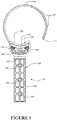
- the clip 100 has a cradle portion 102 for receiving a surface of an item to be secured.
- a flexible member 108 extends from a location 110 at or adjacent an end of the cradle portion 102.
- the flexible member 108 has a free end 112. Formations 114 at or near the free end 112 are configured to engage with other formations 116 which are fixed in relation to the cradle portion 102. When the formations are engaged, the cradle portion 102 and the flexible member 108 define an enclosing loop. By this loop the flexible member 108 may hold an item against the cradle 102.
- the clip also includes a fixing portion 104 with at least one formation 106 extending to be securable to a support. With the fixing portion 104 secured to a support such as a wall, and a conduit enclosed in the loop, the conduit is supported relative to the wall.
- the formations 114 are formed along a length of the flexible member and the formations 116 are formed along a length of the cradle portion. More of the formations progressively engage as the free end of the flexible loop and the cradle overlap more and more by tightening of the loop.
- the formations have a form which prevents loosening of the loop through direct tension on the flexible member.
- An example of suitable formations is a series of teeth. Preferably the profile of the teeth is such that they will pass over each other when relatively moved in one direction, but hook onto each other when relatively moved in the other direction.
- each tooth may have a ramp face and a perpendicular or hook face.
- the cradle 102 is formed as surfaces of an inwardly facing side 121 of a cradle member 120.
- the formations 116 that are fixed in relation to the cradle are located on an outwardly facing side of the cradle member 120.
- the formations 114 on the flexible member 108 are on an inwardly facing surface of the flexible member. In this way, with the flexible member formations and cradle member formations engaged, an item pressing on the cradle 102 (under force from the tightened loop) urges the cradle member formations 114 toward the flexible portion 108.
- the cradle forms part of a socket 130 that receives the free end of the flexible member 108.
- a retaining member 124 is spaced apart from the outwardly facing surface of the cradle member 120. The spacing is sufficient that the free end 112 of the flexible member 108 may pass between the retaining member and the cradle member.
- the cradle member 120 is supported from one or more of the retaining member 124 and the fixing portion 104 by walls 132 and 134 at both sides adjacent an end of the cradle member 120. These walls 132,134, together with the cradle member 120 and the retaining member 124 define an entrance to the socket, into which the free end 112 of the flexible member 108 may be inserted.
- the wall 132 at one side is brief relative to the length of the cradle member 120 and relative to the possible amount of insertion of the free end of the flexible member 108 into the socket. It may also be brief relative to the other wall 134. By brief, it is meant that the wall extends only a small part of the length of the cradle, or other wall, for example less than half the length of the cradle or less than half the length of the other wall.
- the brief wall 132 may be present only in the region immediately adjacent the entrance to the socket. The brief wall may be the only wall on that side of the socket.
- the brief wall 132 is frangible, and may be broken away either partially or completely (preferably by using a tool such as a screw driver, pliers or side cutters) to allow disengagement of the flexible member from the socket by a sideways movement, that would otherwise be blocked by the presence of the brief wall 132.
- the brief wall 132 being adjacent one end of the socket is reasonably accessible by a slender tool, even with a conduit engaged in the clip.
- the other wall 134 includes an opening 140 on the opposite side from the brief wall 132, for example an opening in the other wall 134.
- the opening is spaced from the entrance to the socket.
- a slender tool may be inserted into the opening 140 to act against a portion of the flexible member 108 which is engaged within the socket 130, to push the flexible member sideways so it can be disengaged, after the brief wall 132 has been broken away.
- the form and arrangement of the flexible member 108, the cradle member 120 and the retaining member 124 can be such that the engagement between formations 114 and 116 is enhanced by tension applied to the flexible member 108.
- the free end 112 of the flexible portion 108 has a stiffness sufficient that, when tension is applied to the flexible member 108, the outwardly facing surface or edge of the free end is pressed against the retaining member 124 by pivoting of the free end around an end of the cradle member 120 (at the entrance to the socket). In this way the more tension that is applied the more firmly the formations 114 of the flexible member and 116 of the cradle member are engaged at or adjacent the fulcrum of this pivot.
- the flexible member 108 is sufficiently stiff to be self supporting.
- the flexible member 108 extends in an arc generally away from the cradle portion 102 and fixing portion 104, across above the cradle 102 and back toward the cradle portion 102 and fixing portion104.
- the flexible member 108 is sufficiently flexible for the free end 112 to be moved away from the cradle 102 to open a space sufficient to receive a conduit or pipe. It may be sufficiently flexible to be bent to a condition extending straight away from the cradle or further back toward the supporting wall or structure.
- the flexible member 108 is, in some embodiments, relatively long compared to the cradle 102. For example it may constitute more than half of the perimeter of the loop, or more than two thirds of the perimeter of the loop. This may be the case when the clip 100 is closed to suit a small diameter conduit. When the clip is closed to suit a larger conduit the flexible member may constitute a significantly greater part of the perimeter of the loop.
- the flexible member 108 includes formations 114 distributed along the inner surface for engaging with formations 116 on the cradle member. These formations 114 may extend for a length greater than the length of the cradle member 120. Thus, in use an excess length of flexible member 108 may be trimmed off to allow a clip to be used for smaller conduits.
- the formations 114 of the flexible member and 116 of the cradle member are such that they engage against tension of the flexible member 108.
- the formations are shaped to allow lateral displacement of the flexible member 108 relative to the cradle 102, in the absence of other constraints.
- the formations 114 and 116 may be a series of complementary wide and shallow teeth, the series extending along the flexible member 108 and the cradle member 120.
- the teeth may have steep (or perpendicular or hooked over) surfaces which butt each other to prevent extraction, and ramped surfaces which slide over each other during insertion.
- Other formations are possible, including other forms of teeth, or knobs and holes, or a single engagement on one part and a series of engagements on the other part.
- the teeth could be shaped to provide added security against disengagement.
- they could be shaped to resist sideways disengagement as well as direct tensile extraction.
- the teeth may for example extend at a slanting angle across the flexible member 116, so that the flexible member must undergo further tightening during the sideways displacement required for the teeth to disengage.
- the teeth could have a more complex path, such as chevron or wavy path across the flexible member 116 so that sideways disengagement is essentially precluded.
- the formations could be in some other form that does not allow for disengagement, such as a flexible pawl as part of the socket and a series of notches on the flexible member.
- the flexible member 108 includes ribs 126 on its outward surface.
- the ribs 126 may assist a user to urge the flexible member 108 into greater engagement in the socket 130, helping the user tighten the loop and more tightly secure the item in the clip.
- the flexible member includes at least one zone intended for cutting.
- the cutting zone may be a zone which is thinner or narrower.
- the cutting zone 142 does not have the teeth or other engagements that are present either side of the zone. This essentially defines a region of reduced thickness.
- one or more of the cutting zones 142 also include a shallow groove across the width of the flexible member.
- the member may be shortened to a cutting zone by a user with appropriate tool such as scissors or side cutters.
- each zone 142 is adjacent a rib 126 on the outer surface of the flexible member.
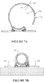
- the zone for cutting is located along the flexible member 108 between the rib 126 and the free end 112. This provides that an outwardly extending rib is located adjacent the new free end of the flexible member after the member 108 is trimmed to one of the cutting zones. This is illustrated by line 700 in Figure 7a .
- This rib, and any other ribs that enter the socket runs on the surface of the retaining member 124, which assists to pivot the inserted portion of the flexible member toward the cradle member, and so bring more of the formations of the socket and the flexible member into an engaged condition.
- the trimmed flexible member is then a suitable length for securing smaller diameter conduit, such as conduit 702 in Figure 7B .
- the spacing of the zones for cutting is shorter than the depth of the socket 130 so that the flexible member does not usually require shortening at a location other than one of the cutting zones.
- the cradle is defined by a concave wall member, the cradle member 120.
- This concave wall member 120 preferably has a curvature tighter than the curvature of the flexible member 108 has, at least with the flexible member in its unengaged condition.
- the concave wall member has a curvature that is between the smallest diameter conduit that the clip is intended to support and the largest diameter conduit that the clip is intended to support.
- the concave wall member 120 preferably ends without sharp corners, for example with radiused corners, to reduce the pinpoint loads that might be imposed on a secured conduit of larger diameter.
- the cradle could be provided by other supporting forms.
- the cradle could comprise a series of two or more members extending across the width of the clip.
- the flexible member 108 extends from a location 110 adjacent one end of the cradle 102, but spaced below (or back from) the inwardly facing surface 121 of the cradle.
- This step back 150 helps to positively locate the supported conduit onto the cradle 102, rather than against the root of the flexible member 108.
- the angle of the strap is sufficiently adaptable to different conduit diameters by flexing in the length of the flexible member that is between its connection with cradle and its contact with the conduit. This action can make easier the tightening of the loop, and lower stresses on the flexible member.
- the area where the flexible member leaves the cradle includes sufficient fillet or radius to alleviate the stress raising sharp corners.
- the fixing portion 104 includes at least one tab portion 106 extending away from the cradle 102.
- the tab portion 106 includes a fixing formation 160 (for example a lug, pin, recess or hole). In some embodiments the tab portion includes more than one fixing formation.
- the tab may be secured to a supporting surface or structure by a suitable fastener, such as a screw 600 through a hole.
- the fixing portion comprises a pair of tabs 106 extending in opposite directions from the cradle 102.
- the tabs have support surfaces 162 for pressing on a mounting surface (for example surface 200 in Figure 6 ) in use.
- the support surfaces 162 are substantially on a plane, and the cradle 102 and flexible member 108 are wholly located to one side of the plane, so that when the support surfaces 162 are against a flat surface, it is the support surfaces 162 that will contact the flat surface, not the cradle 102 or flexible member 108.
- the retaining member 124 extends between the two tabs 106 of the fixing portion, and the cradle 102 is supported in a condition spaced above the retaining member 124.
- the back surface 170 of the retaining member 124 is spaced from the plane of the support surfaces 162 of the tabs 106. This allows the clip to accommodate uneven surfaces, and may also help the clip to flex.
- the fixing portion 104 comprises a tab 300 extending from the cradle 102 in a direction such that a support surface 302 of the tab 300 is on a plane that would intersect the supported conduit. So, for example, the tab 300 forms a supporting post extending away from the loop of the clip, which can be used to space the loop of the clip away from a support structure. Furthermore, as illustrated in Figure 8 , the tab 300 can be fixed to a side face 800 of a structure where the conduit runs across an outer face 802 of the structure.
- Such a clip can find particular use in securing conduit to structural building members such as joists, rafters, studs, nogs or posts.
- the fixing portion of the clip may be movable relative to the cradle.
- the tab 300 may be rotatable on an axis chosen such that the plane of the tab and the plane of the loop can be generally parallel, or generally perpendicular or other angles between. This allows a clip secured, for example, to the side face of a joist or rafter and, protruding beyond the edge of the joist or rafter, to support a conduit running at any angle across the edge face of the joist or rafter.
- the clip is made in more than one part, and these parts are secured together after being made, for example by integrated connection features, or by some additional securing member.
- the clipping portion includes a socket 306 and the fixing portion includes a knob 308.
- the knob 308 engages in the socket 306.
- the disposition of the socket and knob could be reversed.
- the knob may be engaged in the socket by inherent form (for example so that they are engaged in most alignments, but may be withdrawn in one alignment), or by elastic deformation during engagement, or by plastic deformation after engagement (such as mushrooming the end of the knob), or by securing by some form of fastener.
- the knob 308 is secured by a split washer 310, the form of which is illustrated in more detail in Figure 5 .
- the split washer 310 is itself made in two parts 500 and 502 that engage with each other (or with the socket 306, or both).
- the opening 504 in the completed washer is smaller than the opening of the socket through which the knob passes, and smaller than the lateral extent of the knob end.
- the washer 310 prevents the knob 308 being removed from the socket 306.
- Other forms of a washer type clip such as a split ring or circlip), or a split pin or similar fastener, could serve to keep the knob from removal from the socket.
- the illustrated arrangement has the benefit of presenting suitable load bearing surfaces to both the back surfaces of the knob end, and to the internal surfaces of the socket.
- the clip does not have a movable fixing portion, the cradle member, the flexible member and the fixing portion are all formed from a plastic material as a single body.
- the clip via the fixing portion 104, can be slidably adjusted relative to a mounting surface 903 (e.g. a rail 1000).
- the adjustment of the fixing portion 104 to the mounting surface 903 (e.g. rail 1000) may be of an indexed form, such as via indexed formations. In this manner, a series of pre-disposed locator points along the mounting surface (or rail 1000) can be situated.
- the formations may be longitudinally indexed (i.e. along its indexing length) according to a predetermined set of dimensions and step points.
- the index formations may be a series of steps or toothed projections from the mounting surface 903.
- the clip does not have a movable fixing portion.
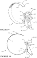
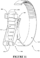
- FIG. 9-14 Illustrated in Figures 9-14 is another embodiment of the clip where the fixing portion 104 comprises of an indexed formation or set of indexed formations 901 having support surfaces 902 for reciprocal engagement or receipt, in use, with a mounting surface 903 comprising a reciprocally indexed formation or set of indexed formations 904.
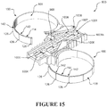
- the embodiment of Figure 15 is a still further embodiment, notably where bosses or a form of extended projection 1001b are provided to facilitate additional structural support for any fasteners (not shown) which may be put through the aperture 1001 to fasten or affix support surface to a member or further support surface.
- the fixing portion 104 may further comprise of at least one and preferably a pair of additional support surfaces 962 disposed toward or at one or each end of the indexed formations 901, the additional support surfaces 962 for location upon or engagement with one or more surfaces of the mounting surface 903 in use.
- a first of the pair of additional support surfaces 962 comprises a pair of lugs 963 disposed toward or at a first end 965 of fixing portion 104.
- the lugs 963 configured to be inserted into (or received by) a respective pair of lug recesses 964 of a mounting surface 903, or alternatively to provide for location of an exterior surface 1007 of the said lugs adjacent or substantially in contact with an inside rail surface indicated as item 1008 in the figures. In this manner, the lugs may facilitate for a slidably locatable clip with respect to the mounting surface 903 or more particularly as the rail 1000.
- the lugs may be more securely fastened to the rail by a fastener which can extend through the aperture 1006 of each such lug, through a lug recess (which then becomes an associate lug aperture previously labelled as item 964), and through the other lug and lug aperture residing on the other side of the mounting surface or rail 1000.
- a fastener may be a threaded fastener or an adjustable fastener allowing for tightening for more secure location and retention of the clip to the mounting surface, or via versa when a re-positioning of the clip to the mounting surface is desired.
- each said lug may be allowed to at least partially project into a lug recess to provide for a positive location of lug with a lug recess and provide for an improved fit and alignment of the respective apertures 1006 with 964.
- the lugs 963 or the lug recesses 964, or both the lugs 963 and the lug recesses 964 are shaped or configured so as to locate and/or retain the lugs, yet allow for a relative rotation of these parts.
- the lugs 963 can be configured to swivel or rotate relative to the mounting surface 904.
- the lugs 963 may themselves comprise rotatable or swivelling element(s) or pivot point with respect to the clip, or the lug recesses 964 may comprises such rotatable or swivelling element(s).
- the lugs 963 may project toward each other, with a gap between their opposing surfaces so as to provide for a clamping region, the mounting surface with the lug recesses 964 to be received within the clamping region.
- the lugs 963 can be dimensioned so as to project into respective lug recesses 964 and provide an effective clamping of the mounting surface 903.
- engagement of the lugs 963 with the lug recesses 964 can facilitate a retention or connection of the first end 965 of the fixing portion 104 to a mounting surface 903.
- the swivelling or rotatable capability can facilitate maintenance or an enduring retention or connection of the fixing portion 104 to the mounting surface 903, yet allow for the clip and indexed formations 901 to be angled or moved away from engagement (whether a full or partial engagement) with the reciprocally indexed formations 904 of the mounting surface 903.
- a second of the pair of additional support surfaces 962 comprises a pair of tabs 966 disposed at or toward a second end 967 of fixing portion 104.
- Each of said tabs 966 is shaped or includes a surface formation 968 to locate with or engage with a said mounting surface 903.
- the shaping or surface formation 968 of the tabs 966 is configured to engage with the mounting surface 903 in a way which allows for a relative ease of connection and disconnection, in use, by a user, yet which is restrained sufficiently so as to preferably avoid an unintended disconnection.
- Haptic feedback can be provided to a user to provide confirmation of when one or both of the first and second additional support surfaces 962 are correctly located or become engaged with the relevant portions of the mounting surface 903. For example, an audible click or snap-type fitment of the lugs 963 or tabs 966 may be generated once engaged with the associated portions of the mounting surface 903.
- the additional support surfaces 962 preferably extend from the fixing portion 104 in a direction that is away from the retaining member 124 and the fixing portion 104.
- the additional support surfaces 962 preferably extend a distance such that their respective location or engagement with the mounting surface 903 is made in conjunction with the simultaneous engagement or mating of the indexed formations 901 of the fixing portion 104 with the reciprocally indexed formations 904.
- the mounting surface 903 can be provided as a rail 1000.
- the rail 1000 can be mounted to a surface, such as a wall ceiling, soffit, floor, joist, gantry or any other structure.
- the mounting surface 903 when in the form of a rail 1000 can be provided as a part of an adjustable clip and mounting assembly.
- the combination of the indexed formations 901 and the reciprocal indexed formations 904 allows for the relative positioning of the fixing portion 104 (and therefore the clip 100) to the mounting surface 903.
- the mounting surface 903 as a rail 1000 comprises of a surface as a slide for receiving the indexed formations 901 of the clip, or the surface is itself comprising of reciprocally indexed formations 904 for reciprocal engagement with the indexed formations 901 projecting from the fixing portion 104. Engagement of these relative indexed formations allows for an indexed positioning or adjustment of the clip and the mounting surface to get other, and to a degree a level of support of each part to the other.
- the mounting surface as a rail 1000 can comprise of one or a series of apertures 1001 for receiving of a fastener.
- the fastener can be used to attach or connect the mounting surface as a rail 1000 to a surface, such as a wall, joist, gantry, soffit or other structure.
- the apertures 1001 may be modified to include a projection or other structure such as a bossed arrangement 1001b.
- a fastener or other securement device which is provided through the aperture 1001 has increased structural capabilities and may help to reduce or ameliorate deflection or distortion or other bending or geometric variance in the shape of the mounting surface 903, particular when as a rail 1000. Changes in shape of the rail 1000 may impede the ability for the clip to be slidably re-positioned or re-located along the mounting surface or rail 1000, particularly if there has been a deflection or distortion of the stepped regions 1003.
- fasteners can be used to connect the fixing portion 104 of another of the clip embodiments thereto.
- the fixing portion 104 as shown in Figures 1 , 3 , 4 itself has a fixing formation 160 (e.g. an aperture) for receiving therethrough a fastener which can be connected to the mounting surface as a rail 1000 and through the apertures 1001 into a structure.
- the apertures 1001 can be located along a length of the rail 1000, and may be centrally located.
- the rail 1000 may be provided in a laddered formation, for example with the indexed formations 904 being provided on opposing sides or surfaces of the rail, with a series or sections or bridges or runs 1005.
- Each of the sections or bridges or rungs 1005 may be longitudinally displaced from each other (i.e. in a laddered formation) with a series of cut-out portions 1004 interposed between.
- the laddered formation may provide for increased structural rigidity, in association with bosses 1001b.
- material may be removed from other regions of the rail 1000 to minimise the quantity of material used in manufacture of such a rail.
- the cut-out regions may themselves provide a user with additional voids or apertures through which fasteners may be inserted, or alternatively may provided a user with additional access points for use when putting such a rail 1000 into use.
- the mounting surface as a rail 1000 can comprise of one or a series of lug recesses 964. Such lug recesses can be located along a length of the rail 1000, and may be located along one or multiple edge regions 1002 of the rail 1000 for receipt of lugs 963.
- the mounting surface as a rail 1000 can comprise of a stepped region 1003 along one or multiple edge region 1002 substantially adjacent to the reciprocally indexed formations 904.
- a stepped region 1003 can provide a suitable structure for retaining or locating of the shaped or surface formation 968 of a tab 966.
- the one of the fixing portion 104 or the mounting surface 903 may comprise of indexed formations, and the other of the fixing portion 104 of the mounting surface may comprise of a member (not shown) reciprocally engageable with a said indexed formation, i.e. both parts may not necessarily comprise of a plurality of indexed formations.
- Figures 12 , 13 and 15 show a rail 1000 with attached clips, being in one preferred orientation (i.e. where lugs 963 are positioned in-use to be above the tabs 966 when mounted on a rail in a vertical position, it will be appreciated such orientation of clips on the rail in-use may be varied and may, for example, be reversed (i.e. lugs 963 may be at the bottom of the clip when in the indexed position with the rail, and the tabs 966 may be above these, again when in a vertical orientation of the rail).
- ribs 126 may be provided. Increasing the frequency and number of ribs 126 positioned along a length of the flexible member 108 may help to reduce variance or tolerance in the connection of the associated teeth 114 with those formations or teeth 116 of the cradle.
- a numerically associated index may be provided for the indexed formations along the mounting surface or rail so as to provide a user with an indication of the length of adjustment of a clip relative to the mounting surface or rail 1000.
- a scale or other guides may be provided along the length of a rail 1000.
- Two or more rails 1000 may be connected to each other to provide for an extended rail system.
- a connector (not shown) may be provided for securing the ends of a pair of rails together in a manner which still allows for a clip connected to the rail 1000 to straddle the ends (and the jointed connection) of these rails.
- a plurality of rails can be provided in jointed connection with each other for rail lengths as desired by a user.
- Such a connector may connect to each end of the rails through associated male and female parts on the connector and rails themselves.
- other connector systems may be utilised, preferably such that there is no impedance to the ability to adjustably slide a clip along a rail, through a jointed connection and onto a connected rail.
- the parts of the clip may be formed from a plastic material.
- the plastic may be, for example, selected from the following: plastics/polymers of the types such as: polypropylene (PP), polyethylene (PE), polyvinyl chloride (PVC), acrylonitrile-butadiene-styrene (ABS), thermoplastic elastomers (TPE), including Styrenic block copolymers (TPE-s), polyolefin blends (TPE-o), Elastomeric alloys (TPE-v orTPV), thermoplastic ployurethanes (TPU), Thermoplastic copolyester, Thermoplastic polyamides, nylons, acetal polymers, polycarbonates, thermoplastics, polyurethanes
- PP polypropylene
- PE polyethylene
- PVC polyvinyl chloride
- ABS acrylonitrile-butadiene-styrene
- TPE thermoplastic elastomers
- TPE-s Sty
- the clip be made of a lightweight and durable material which is able to accommodate some degree of flexion.
- suitable materials are plastics/polymers of the types such as: polypropylene (PP), polyethylene (PE), polyvinyl chloride (PVC), acrylonitrile-butadiene-styrene (ABS), thermoplastic elastomers (TPE), including Styrenic block copolymers (TPE-s), polyolefin blends (TPE-o), Elastomeric alloys (TPE-v or TPV), thermoplastic ployurethanes (TPU), Thermoplastic copolyester, Thermoplastic polyamides, nylons, acetal polymers, polycarbonates, thermoplastics, polyurethanes or a very ductile metal e.g. soft temper aluminium.
- PP polypropylene
- PE polyethylene
- PVC polyvinyl chloride
- ABS acrylonitrile-butadiene-styrene
- the pipes which are to be located by the clip of this invention are those typically used in plumbing applications, but may also include other cables or accessories to be retained (e.g. a bundle of cables perhaps), and these may come in a variety of types and have differing wall thicknesses depending on the manufacturer, the pressure rating, the material used, the requirements of the particular application and/or the industry involved.
- Common types of pipes used are, copper, polybutylene or polymers of butylene, pex pipe (white) such as cross-linked polyethylene, PVC (poly vinyl chloride), multi-layer composite aluminium, galvanised metals, stainless steels.
- a clip which has a fixing portion spanning about 100mm may have a cradle about 30mm long, a flexible member about 160mm long, and be able to accommodate conduit with an outer diameter ranging between 32mm and 50mm.
- a clip could have dimensions suitably scaled up.
- the clip could have dimensions suitably scaled down.
- the loop can be at least 50mm diameter.
- the clip is intended to hold a pipe or conduit of an outer diameter (OD) of about 80 to 100 mm, or about 100 to 150mm.
- OD outer diameter
- the flexible member is of an appropriate length to accommodate such different pipe or conduit outer diameters.
- the width of the cradle may be any width necessary to suitably accommodate a pipe or conduit or other structure to be retained, and may preferably be about 20 to 30mm, or may be about 22 to 25mm.
- the clip may be sized and dimensioned to preferably accommodate pipes having an outer diameter (OD) of about 80 to 100mm.
- OD outer diameter
- the length of the cradle portion may be about 30mm, and the width of the cradle may be about 18mm, the width of the flexible member may be about 14mm.
- the required length of the flexible member depends on the size of the pipe to be accommodated, however for 80mm OD pipes, a length of the flexible member may be about 270mm and for 100mm OD pipes, the length of the flexible member may be about 340mm.
- the clip may be sized and dimensioned to accommodate pipes having an outer diameter (OD) of about 100 to 150mm.
- the length of the cradle portion may be about 50mm, and the width of the cradle may be about 18mm, the width of the flexible member may be about 14mm.
- the required length of the flexible member depends on the size of the pipe to be accommodated, however for 100mm OD pipes, a length of the flexible member may be about 340mm and for 150mm OD pipes, the length of the flexible member may be about 485mm.
- the formations on the flexible member may extend at least 60mm along the flexible member (such that the loop will accommodate items with diameter variations up to approximately 18 mm).
- the clip may be any width sufficient to provide a desired level of strength.
- the width is preferably much smaller than the overall dimension. So for example the width of the clip could be less than about 10% of the length of the flexible member.
- Flexibility to an extent that does not detract from security and strength of the clip, is considered advantageous for allowing the clip to fully open to receive conduit (by bending up or back the flexible member), for allowing the clip to be readily closed, and for allowing some movement of the clip portion relative to the fixing portion to allow for imperfect placement of the clip or allow for unevenness of the surface to which the clip is secured. Flexibility arises from a combination of the material property (the stiffness of the plastic material and the degree of elastic yield possible with the material), and the dimensions and form of the parts of the clip. For example the flexible member is much longer than it is wide, and much wider than it is thick. In particular the thickness may only be 2 to 4 mm.
- the tabs of the fixing portion are also 2mm to 4mm thick, allowing them to flex adjacent the location that they connect to the cradle structure.
Landscapes
- Engineering & Computer Science (AREA)
- General Engineering & Computer Science (AREA)
- Mechanical Engineering (AREA)
- Architecture (AREA)
- Civil Engineering (AREA)
- Structural Engineering (AREA)
- Clamps And Clips (AREA)
- Supports For Pipes And Cables (AREA)
Claims (18)
- Schelle (100) zum Sichern eines Abschnitts eines langen dünnen Gegenstands, wie etwa eines Kabels oder eines Rohres, die Folgendes umfasst:
einen Gestellabschnitt (102) zum Aufnehmen einer Oberfläche eines zu sichernden Gegenstands, einen Befestigungsabschnitt (104) mit wenigstens einer Formation (116), die sich erstreckt, um an einer Stütze geischert werden zu können, und ein flexibles Element (108), das sich von einer Stelle an oder angrenzend einem Ende des Gestellabschnitts erstreckt, wobei das flexible Element ein freies Ende (112) und Formationen (114) an oder nahe dem freien Ende aufweist, um mit anderen Formationen in Eingriff zu stehen, die bezüglich des Gestellabschnitts derart befestigt sind, dass der Gestellabschnitt und das flexible Element eine umschließende Schleife derart definieren, dass das flexible Element einen Gegenstand gegen das Gestell halten kann, wobei eine äußere Oberfläche des flexiblen Elements Rippen (126) enthält, und wobei eine oder mehrere der Rippen, wenn sie mit dem Gestell in Zusammenarbeit stehen, die Formationen des flexiblen Elements in einen größeren Eingriff in eine Fassung (130) des Gestells drängt. - Schelle nach Anspruch 1, wobei die Formationen beim Anziehen der Schlaufe progressiv in Eingriff stehen und ein Lösen der Schlaufe durch direkte Spannung auf das flexible Element verhindern.
- Schelle nach Anspruch 1 oder 2, wobei das Gestell als Oberflächen einer nach innen gerichteten Seite eines Gestellelements (120) ausgebildet ist und die anderen Formationen auf einer nach außen gerichteten Seite des Gestellelements derart angeordnet sind, dass, bei Verwendung, ein Gegenstand, der auf das Gestell drückt, die Gestellelementformationen in Richtung des flexiblen Abschnitts drängt.
- Schelle nach Anspruch 3, wobei ein Halteelement (124) von der nach außen gerichteten Seite des Gestellelements ausreichend weg beabstandet ist, dass das freie Ende des flexiblen Abschnitts zwischen dem Halteelement und dem Gestellelement hindurchgeführt werden kann, wobei die Form und die Anordnung des flexiblen Elements, des Gestellelements und des Halteelements derart sind, dass der Eingriff zwischen den Formationen durch eine auf das flexible Element ausgeübte Spannung verstärkt wird, wobei optional das freie Ende des biegsamen Abschnitts eine ausreichende Steifigkeit aufweist, dass die nach außen gerichtete Oberfläche oder Kante des freien Endes gegen das Halteelement anliegt, indem das freie Ende um ein Ende des Gestellelements drehbar ist, wenn Spannung auf das biegsame Element angewandt wird, wobei der Eingriff zwischen den Ausbildungen des biegsamen Elements und des Gestellelements an oder angrenzend dem Hebelpunkt dieses Drehpunkts ist.
- Schelle nach einem der Ansprüche 1 bis 4, wobei der Befestigungsabschnitt wenigstens einen Laschenabschnitt (106) enthält, der sich von dem Gestell weg erstreckt, wobei der Laschenabschnitt eine Befestigungsformation (160) enthält.
- Schelle nach einem der Ansprüche 1 bis 5, wobei das flexible Element ausreichend steif ist, um selbststützend zu sein, und sich in einem Bogen im Allgemeinen von dem Gestell- und Befestigungsabschnitts weg, über die Halterung hinweg und zurück in Richtung des Gestell- und Befestigungsabschnitts derart erstreckt, dass das flexible Element mehr als die Hälfte des Umfangs der Schleife definiert.
- Schelle nach einem der Ansprüche 1 bis 6, wobei das flexible Element Formationen enthält, die entlang der inneren Oberfläche über eine Länge verteilt sind, die größer als die Länge des Gestellelements ist.
- Schelle nach einem der Ansprüche 1 bis 7, wobei eine oder mehrere der Rippen, die in die Fassung des Gestells eindringen, auf der Oberfläche des Halteelements laufen, um einen eingeschobenen Abschnitt des flexiblen Elements in Richtung des Gestells zu drehen, und bei Verwendung, Fördern oder Bringen von Formationen der Fassung und des flexiblen Elements in einen Eingriffszustand.
- Schelle nach einem der Ansprüche 1 bis 8, wobei das flexible Element eine Zone (142) enthält, die vorgesehen ist, um derart zu schneiden, dass das Element bis zu der Zone gekürzt werden kann, wobei die Zone zum Schneiden optional an eine Rippe auf der äußeren Oberfläche angrenzend ist, die entlang des flexiblen Elements zwischen der Rippe und dem freien Ende angeordnet ist.
- Schelle nach einem der Ansprüche 4 bis 9, wobei das Gestellelement von einem oder mehreren des Halteelements und des Befestigungsabschnitts durch Wände (132, 134) an beiden Seiten neben einem Ende des Gestellelements gestützt wird, um eine Fassung zu hinterlassen, in die das freie Ende des flexiblen Elements eingeschoben werden kann, wobei die Fassung durch das Halteelement, das Gestellelement und die Wände definiert ist.
- Schelle nach Anspruch 10, wobei die Wand an einer Seite zerbrechlich ist, derart ausgebildet, um leicht entfernt oder passierbar gemacht zu werden.
- Schelle nach Anspruch 11, wobei die Fassung eine Öffnung (140) auf der der zerbrechlichen Wand gegenüberliegenden Seite enthält, wobei die Öffnung von dem Eingang der Fassung beabstandet ist, wobei bei Verwendung ein Werkzeug in die Öffnung eingeschoben werden kann, um gegen einen Abschnitt des flexiblen Elements zu wirken, der in Eingriff mit der Fassung steht
- Schelle nach einem der Ansprüche 1 bis 12, wobei die Formationen derart sind, dass sie gegen die Spannung des flexiblen Elements in Eingriff stehen, aber eine seitliche Verschiebung des flexiblen Elements relativ zu dem Gestell in Abwesenheit anderer Einschränkungen erlauben.
- Schelle nach einem der Ansprüche 1 bis 13, wobei der Befestigungsabschnitt ein Paar Laschen (106) mit Stützoberflächen (162) zum Drücken auf eine Montageoberfläche bei Verwendung umfasst, wobei die Stützoberflächen im Wesentlichen auf einer Ebene sind, wobei die Wiege und das flexible Element vollständig auf einer Seite der Ebene angeordnet sind.
- Schelle nach Anspruch 14, wenn er von Anspruch 4 abhängig ist, wobei sich das Halteelement zwischen den Laschen des Befestigungsabschnitts erstreckt, wobei das Gestell optional in einem über dem Halteelement beabstandeten Zustand gestützt wird, wobei das Halteelement optional von der Ebene beabstandet ist.
- Schelle nach einem der Ansprüche 1 bis 15, wobei sich das flexible Element von einer Stelle angrenzend an ein Ende des Gestells, aber mit Abstand unter der Oberfläche des Gestells erstreckt.
- Schelle nach einem der Ansprüche 1 bis 16, wobei der Befestigungsabschnitt oder die Stütze oder beide gerasterte Formationen (901) zum gerasterten Positionieren der Schelle und der Stütze umfassen, wobei der Befestigungsabschnitt optional eine gerasterte Formation oder einen Satz gerasterte Formationen mit Stützoberflächen (962) für den gegenseitigen Eingriff oder die Aufnahme bei Verwendung mit einer Montageoberfläche (903) umfasst, die eine gegenseitig gerasterter Formation oder einen Satz gerasterte Formationen umfasst, wobei der Befestigungsabschnitt optional ferner wenigstens eine zusätzliche Stützoberfläche (962) umfasst, die in Richtung auf oder an einem oder jedem Ende der gerasterten Formationen angebracht ist, wobei die zusätzliche Stützoberfläche zur Anordnung auf oder zum Eingriff mit einer oder mehreren Oberflächen der Montageoberfläche bei Verwendung ist, wobei der Befestigungsabschnitt optional ein Paar zusätzlicher Stützoberflächen umfasst, eine erste des Paars zusätzlicher Stützoberflächen ein Paar Nasen (963) umfasst, die in Richtung auf oder an einem ersten Ende des Befestigungsabschnitts angebracht sind, wobei die Nasen optional konfiguriert sind, um, bei Verwendung, angrenzend zu einem entsprechenden Paar Nasenaussparungen (964) der Montageoberfläche angeordnet oder in diese eingeschoben (oder von diesen aufgenommen) werden, wobei die Nasen oder die Nasenaussparungen oder sowohl die Nasen als auch die Nasenaussparungen geformt oder konfiguriert sind, dass sie die Nasen anordnen und/oder halten, und optional eine relative Rotierung der entsprechenden Nase und der Nasenaussparung ermöglichen, wobei optional eine oder jede der Nasen relativ zu der Montageoberfläche oder der Nasenaussparung schwenkbar oder rotierbar ist, optional eine oder jede der Nasen ein rotierbares oder schwenkbares Teil/rotierbare und schwenkbare Teile oder ein drehbares Teil oder einen Punkt in Bezug auf die Schelle umfassen, oder die Nasenaussparungen ein rotierbares oder schwenkbares oder ein drehbares Teil/rotierbare oder schwenkbare oder drehbare Teile oder einen Punkt umfassen, oder jede der Nasen und der Nasenaussparungen ein rotierbares oder schwenkbares oder drehbares Teil/rotierbare oder schwenkbare oder drehbare Teile oder einen Punkt umfassen, wobei optional jede Nase eines Paares Nasen mit einem Spalt zwischen ihren gegenüberliegenden Oberflächen aufeinander zu ragen, damit ein Klemmbereich entsteht, wobei die Montageoberfläche mit den Nasenaussparungen innerhalb des Klemmbereichs aufgenommen wird, wobei optional der Eingriff der Nasen mit den Nasenaussparungen ein Halten oder Verknüpfen des ersten Endes des Befestigungsabschnitts mit einer Montageoberfläche erleichtert, wobei optional die Schelle in Bezug auf einen Verknüpfungspunkt der Nasen mit den Nasenaussparungen schwenkbar oder rotierbar oder drehbar ist, jedoch eine Verknüpfung mit der Montageoberfläche aufrechterhält, wobei optional eine zweite des Paars zusätzlicher Stützoberflächen ein Paar Nasen (966) umfasst, die an oder zu einem zweiten Ende des Befestigungsabschnitts angebracht sind, wobei optional eine oder jede der Nasen geformt ist oder eine Oberflächenformation (968) enthält, um mit einer der Montageoberfläche angeordnet oder in diese eingeschoben zu werden (oder sie zu verknüpfen), wobei optional das Formen oder Oberflächenformation der oder jeder der Nasen konfiguriert, um, bei Verwendung, mit der Montageoberfläche in Eingriff zu stehen, was eine Verknüpfung und Trennung, bei Verwendung, durch einen Benutzer ermöglicht, die jedoch ausreichend zurückgehalten wird, um eine unbeabsichtigte Trennung zu vermeiden, wobei sich die zusätzlichen Stützoberflächen von dem Befestigungsabschnitt in einer Richtung erstrecken, die von dem Halteelement und dem Befestigungsabschnitt weg ist, wobei sich die zusätzlichen Stützoberflächen optional derart weit erstrecken, dass ihre entsprechende Anordnung oder ihr Eingriff mit der Montageoberfläche zusammen mit dem gleichzeitigen Eingriff oder der Paarung der gerasterten Formationen des Befestigungsabschnitts mit den wechselseitig gerasterten Formationen erfolgt.
- Schelle nach Anspruch 17, wobei die Montageoberfläche eine Schiene (1000) ist, wobei optional die Schiene an einer anderen Oberfläche oder Montageoberfläche montierbar ist, wobei optional die Montageoberfläche, wenn in Form einer Schiene, als Teil einer einstellbaren Schellen- und Montageanordnung vorgesehen ist, wobei die Anordnung eine Kombination der gerasterten Formationen und der wechselseitig gerasterten Formationen und die relative Positionierung des Befestigungsabschnitts (und daher der Schelle) zur Montageoberfläche vorgesehen ist, wobei optional die Schiene eine Oberfläche als Schlitten zum Aufnehmen der gerasterten Formationen der Schelle umfasst, oder die Oberfläche selber wechselseitig gerasterten Formationen zum wechselseitigen in Eingriff stehen mit den gerasterten Formationen umfasst, die von dem Befestigungsabschnitt der Schelle vorstehen, wobei optional der Eingriff der entsprechenden gerasterten Formationen mit der Schelle und der Schiene ein gerasterten Positionieren oder Einstellen der Schelle und der Schiene zueinander ermöglicht, und/oder zum Bereitstellen einer Stütze für jedes Teil füreinander, wobei die Schiene optional eine oder eine Reihe von Öffnungen (1001) zur Aufnahme eines Verbindungselements umfasst, wobei das Verbindungselements zum Anschlagen oder Verknüpfen der Schiene mit einer Oberfläche oder einer anderen Montageoberfläche umfasst, wobei optional die Öffnungen entlang einer Länge der Schiene angeordnet ist, optional zentral entlang einer Länge der Schiene angeordnet sein kann, wobei optional der Befestigungsabschnitt eine oder mehrere Befestigungsformationen zum Aufnehmen eines Verbindungselements dorthindurch zum Verbinden mit der Schiene und durch die Öffnungen in eine weitere Montageoberfläche oder eine Struktur umfasst, wobei optional die Schiene eine oder Reihe von Nasenaussparungen umfasst, wobei jede der Nasenaussparungen entlang einer Länge der Schiene angeordnet ist und optional entlang eines oder mehrerer Randbereiche der Schiene zur Aufnahme der Nasen angeordnet sein kann, wobei die Schiene optional einen abgestuften Bereich (1003) entlang eines oder mehrerer Randbereiche im Wesentlichen angrenzend an die wechselseitig gerasterten Formationen umfasst, wobei der abgestufte Bereich eine Struktur zum Halten oder Anordnen der Form- oder Oberflächenformation einer oder beider Nasen ist, die sich von dem Befestigungsabschnitt aus erstrecken, wobei die Schelle optional rotierbar ist, wie etwa durch Schwenken oder Rotieren oder Drehen, weg von der Montageoberfläche in einer Weise, um gerasterte Formationen der Schelle von gerasterten Formationen der Montageoberfläche zu lösen.
Applications Claiming Priority (2)
| Application Number | Priority Date | Filing Date | Title |
|---|---|---|---|
| NZ62652614 | 2014-06-20 | ||
| PCT/IB2015/054610 WO2015193841A1 (en) | 2014-06-20 | 2015-06-19 | A multi-fit clip |
Publications (3)
| Publication Number | Publication Date |
|---|---|
| EP3158246A1 EP3158246A1 (de) | 2017-04-26 |
| EP3158246A4 EP3158246A4 (de) | 2018-02-07 |
| EP3158246B1 true EP3158246B1 (de) | 2020-02-19 |
Family
ID=54934934
Family Applications (1)
| Application Number | Title | Priority Date | Filing Date |
|---|---|---|---|
| EP15808971.4A Active EP3158246B1 (de) | 2014-06-20 | 2015-06-19 | Klammer mit mehrfacher passform |
Country Status (6)
| Country | Link |
|---|---|
| US (2) | US10001226B2 (de) |
| EP (1) | EP3158246B1 (de) |
| CN (1) | CN106415101B (de) |
| AU (1) | AU2015275725B2 (de) |
| CA (1) | CA2947811C (de) |
| WO (1) | WO2015193841A1 (de) |
Cited By (1)
| Publication number | Priority date | Publication date | Assignee | Title |
|---|---|---|---|---|
| EP4468540A1 (de) * | 2023-05-22 | 2024-11-27 | ABB Schweiz AG | Kabelhalter für kollaboratives roboterkabelmanagement |
Families Citing this family (25)
| Publication number | Priority date | Publication date | Assignee | Title |
|---|---|---|---|---|
| BR102012024461B1 (pt) * | 2012-09-26 | 2021-04-20 | Tigre S.A. Participações | abraçadeira para fixação de tubos |
| WO2016082848A1 (en) * | 2014-11-25 | 2016-06-02 | Volvo Truck Corporation | Self-fastened bracket for mounting a wire harness to a support structure of a vehicle and vehicle comprising the same |
| TWI555664B (zh) * | 2015-09-17 | 2016-11-01 | 陳金柱 | 固定裝置 |
| EP3284992B1 (de) * | 2016-08-17 | 2018-11-28 | Walter Stauffenberg Gmbh & Co. Kg | Vorrichtung zur befestigung von leitungen |
| CN109282085A (zh) * | 2017-07-21 | 2019-01-29 | 德梅斯特(上海)环保科技有限公司 | 管道固定装置及管道固定系统及管道部件集合 |
| CN107605882A (zh) * | 2017-08-31 | 2018-01-19 | 安徽凯瑞汽配制造有限公司 | 一种无缝压圈式紧固件 |
| EP3550291A1 (de) * | 2018-04-05 | 2019-10-09 | Georg Fischer Rohrleitungssysteme AG | Befestigungsvorrichtung für messgeräte an rohren |
| US10439381B1 (en) * | 2018-07-10 | 2019-10-08 | The Boeing Company | Electrical raceway system and associated wire bundle clamp system and method |
| CN109093552A (zh) * | 2018-08-31 | 2018-12-28 | 深圳市纯水号水处理科技有限公司 | 一种智能化纯水系统滤芯更换防掉落磁吸式弹簧扣 |
| US10704710B2 (en) * | 2018-11-20 | 2020-07-07 | The Boeing Company | Easy lock P-clamp |
| CN111268020B (zh) * | 2018-12-04 | 2025-04-01 | 禧玛诺(新)私人有限公司 | 夹紧箍和包括夹紧箍的自行车部件 |
| CN109973786B (zh) * | 2019-03-11 | 2023-12-22 | 浙江工业大学 | 一种用于固定便携式压入仪的万能支座 |
| GB2585748B (en) * | 2019-05-11 | 2023-09-06 | Gripple Ltd | Connecting device |
| US10745182B1 (en) * | 2019-05-24 | 2020-08-18 | A. Raymond Et Cie | Releasable tie-strap fastener |
| US11661759B2 (en) * | 2019-08-13 | 2023-05-30 | Eaton Intelligent Power Limited | Attachment device for a non-structural component of a building |
| KR20210108898A (ko) * | 2020-02-26 | 2021-09-03 | 일리노이즈 툴 워크스 인코포레이티드 | 다중 부품 클램프 |
| US11142381B1 (en) * | 2020-07-27 | 2021-10-12 | Hellermann Tyton Corporation | Saddle that adjusts to a bundle diameter |
| CN112588881A (zh) * | 2020-12-07 | 2021-04-02 | 湖南鸿云钢模科技有限公司 | 一种用于钢管修复的加固结构 |
| CN113695933B (zh) * | 2021-08-16 | 2023-12-08 | 成都飞机工业(集团)有限责任公司 | 一种多曲率长条类零件柔性切割夹具及切割方法 |
| US11677222B1 (en) | 2021-12-28 | 2023-06-13 | Panduit Corp. | Winged cable mount |
| US12316089B2 (en) * | 2022-08-09 | 2025-05-27 | Southwire Company, Llc | Cable stacker |
| USD1039960S1 (en) * | 2022-09-29 | 2024-08-27 | Canadian Tire Corporation, Limited | Channel fastener clip |
| US20240360922A1 (en) | 2023-04-28 | 2024-10-31 | Hellermanntyton Corporation | Cable Tie Cradle Mount Fixings |
| EP4507146A1 (de) * | 2023-08-07 | 2025-02-12 | Abb Schweiz Ag | Kabelhalter, kabelmontagekit und verwendung des kabelhalters und des kabelmontagekits |
| CN117404528B (zh) * | 2023-12-14 | 2024-03-29 | 临汾淼森能源工程有限公司 | 一种供热工程施工用管道固定装置 |
Family Cites Families (19)
| Publication number | Priority date | Publication date | Assignee | Title |
|---|---|---|---|---|
| US2632217A (en) * | 1952-03-04 | 1953-03-24 | Tinnerman Products Inc | Separable clamping device |
| US3913876A (en) * | 1972-08-24 | 1975-10-21 | Panduit Corp | Cable tie support |
| US4462141A (en) * | 1981-07-17 | 1984-07-31 | Virginia Plastics Company | Flexible locking clamp used with tubular guard for linear body |
| US4447934A (en) * | 1982-06-07 | 1984-05-15 | National Molding Corporation | Cable harness |
| US4510650A (en) * | 1983-12-28 | 1985-04-16 | Hollingsead International, Inc. | Cable clamp assembly |
| US4862561A (en) * | 1988-12-21 | 1989-09-05 | Designs By Master Markets, Inc. | Irreversible tie strap with specialized clasp |
| JP2604677Y2 (ja) * | 1992-03-05 | 2000-05-22 | 大和化成工業株式会社 | ベルトクランプ |
| US5332179A (en) * | 1992-12-30 | 1994-07-26 | Panduit Corp. | 2-way box mount |
| ES2164836T3 (es) * | 1995-09-19 | 2002-03-01 | Daiwa Kasei Kogyo Kk | Patas de retencion de un componente. |
| US5794461A (en) * | 1995-10-13 | 1998-08-18 | The Mckinley Group | Key operable restraining device |
| US6126122A (en) * | 1997-11-06 | 2000-10-03 | Sioux Chief Manufacturing Co., Inc. | Double ratchet arm pipe clamp |
| US6402096B1 (en) * | 1997-11-06 | 2002-06-11 | Sioux Chief Mfg. Co., Inc. | Apparatus for supporting conduit between building members |
| US6149109A (en) * | 1999-05-20 | 2000-11-21 | Stankowski; Ralph | Cable mount construction |
| JP4689986B2 (ja) * | 2004-07-21 | 2011-06-01 | 株式会社パイオラックス | バンドクランプ |
| US7178203B2 (en) * | 2005-02-28 | 2007-02-20 | Illinois Tool Works Inc | Anti-removal ratchet clip |
| US7861981B2 (en) * | 2008-10-22 | 2011-01-04 | Pratt & Whitney Canada Corp. | Protective saddle mount for cable tie |
| CN102472415B (zh) * | 2009-07-07 | 2017-07-07 | 伊利诺斯工具制品有限公司 | 自定心的电缆扎带 |
| US8955198B2 (en) * | 2011-08-28 | 2015-02-17 | Jeffrey D. Carnevali | Releasable strap mount |
| CN202733190U (zh) * | 2012-08-09 | 2013-02-13 | 宏泰电器有限公司 | 可松式加强扎线带 |
-
2015
- 2015-06-19 EP EP15808971.4A patent/EP3158246B1/de active Active
- 2015-06-19 CA CA2947811A patent/CA2947811C/en active Active
- 2015-06-19 CN CN201580026236.5A patent/CN106415101B/zh active Active
- 2015-06-19 WO PCT/IB2015/054610 patent/WO2015193841A1/en not_active Ceased
- 2015-06-19 AU AU2015275725A patent/AU2015275725B2/en active Active
- 2015-06-19 US US15/317,540 patent/US10001226B2/en active Active
-
2018
- 2018-05-15 US US15/980,444 patent/US10527200B2/en active Active
Non-Patent Citations (1)
| Title |
|---|
| None * |
Cited By (1)
| Publication number | Priority date | Publication date | Assignee | Title |
|---|---|---|---|---|
| EP4468540A1 (de) * | 2023-05-22 | 2024-11-27 | ABB Schweiz AG | Kabelhalter für kollaboratives roboterkabelmanagement |
Also Published As
| Publication number | Publication date |
|---|---|
| US10001226B2 (en) | 2018-06-19 |
| US20170122459A1 (en) | 2017-05-04 |
| CN106415101B (zh) | 2020-09-25 |
| EP3158246A4 (de) | 2018-02-07 |
| EP3158246A1 (de) | 2017-04-26 |
| WO2015193841A1 (en) | 2015-12-23 |
| CN106415101A (zh) | 2017-02-15 |
| CA2947811C (en) | 2022-08-16 |
| AU2015275725A1 (en) | 2016-11-17 |
| CA2947811A1 (en) | 2015-12-23 |
| US10527200B2 (en) | 2020-01-07 |
| AU2015275725B2 (en) | 2020-10-15 |
| US20190113155A1 (en) | 2019-04-18 |
Similar Documents
| Publication | Publication Date | Title |
|---|---|---|
| EP3158246B1 (de) | Klammer mit mehrfacher passform | |
| US11705703B2 (en) | Adjustable P-clamp with multiple mounting options | |
| EP3256765B1 (de) | Rohrschelle | |
| EP2492563B1 (de) | Klemme für Leitung oder Kabel | |
| US20110126934A1 (en) | Clamp for securing a pipe to a supporting structure | |
| EP3682150B1 (de) | Rohrstützstruktur | |
| US7152832B2 (en) | Pipe support apparatus | |
| US6685144B1 (en) | Pipe support apparatus | |
| EP2531762A1 (de) | Mehrfach positionierbare rohraufhängeklemme | |
| US20040094681A1 (en) | Bracket element | |
| US20070080265A1 (en) | Automatically self-locking utility clamp | |
| US20050121559A1 (en) | Simplified pipe support assembly | |
| EP1975491A1 (de) | Schnappklemme, insbesondere zur Stützung von Stromverteilungsleitungen | |
| US9054510B2 (en) | Utility meter socket and conduit and method of installation | |
| JP2003314750A (ja) | 配管支持具 | |
| EP2550473B1 (de) | Klemme | |
| JP2002081212A (ja) | 仮囲い板 | |
| JP4288272B2 (ja) | 竪樋の取付具及びこれを用いた竪樋の取付構造 | |
| JP4849904B2 (ja) | メッセンジャーワイヤーの架設方法 | |
| JP6852900B2 (ja) | 配管取付け金具 | |
| EP1771676B1 (de) | Schlauchklemme | |
| NZ569449A (en) | Resilient mounting for an inline fan for ducting systems | |
| KR20180002753U (ko) | 가스 배관 고정장치 | |
| JPH11223279A (ja) | 配管ダクトと脚部材との接続構造 | |
| JP2020037841A (ja) | 屋根安全具取付金具 |
Legal Events
| Date | Code | Title | Description |
|---|---|---|---|
| STAA | Information on the status of an ep patent application or granted ep patent |
Free format text: STATUS: THE INTERNATIONAL PUBLICATION HAS BEEN MADE |
|
| PUAI | Public reference made under article 153(3) epc to a published international application that has entered the european phase |
Free format text: ORIGINAL CODE: 0009012 |
|
| STAA | Information on the status of an ep patent application or granted ep patent |
Free format text: STATUS: REQUEST FOR EXAMINATION WAS MADE |
|
| 17P | Request for examination filed |
Effective date: 20170120 |
|
| AK | Designated contracting states |
Kind code of ref document: A1 Designated state(s): AL AT BE BG CH CY CZ DE DK EE ES FI FR GB GR HR HU IE IS IT LI LT LU LV MC MK MT NL NO PL PT RO RS SE SI SK SM TR |
|
| AX | Request for extension of the european patent |
Extension state: BA ME |
|
| DAV | Request for validation of the european patent (deleted) | ||
| DAX | Request for extension of the european patent (deleted) | ||
| A4 | Supplementary search report drawn up and despatched |
Effective date: 20180110 |
|
| RIC1 | Information provided on ipc code assigned before grant |
Ipc: F16L 3/10 20060101ALI20180104BHEP Ipc: F16L 3/137 20060101AFI20180104BHEP Ipc: H02G 3/32 20060101ALI20180104BHEP Ipc: F16B 2/08 20060101ALI20180104BHEP Ipc: F16L 3/24 20060101ALI20180104BHEP |
|
| GRAP | Despatch of communication of intention to grant a patent |
Free format text: ORIGINAL CODE: EPIDOSNIGR1 |
|
| STAA | Information on the status of an ep patent application or granted ep patent |
Free format text: STATUS: GRANT OF PATENT IS INTENDED |
|
| INTG | Intention to grant announced |
Effective date: 20190906 |
|
| GRAS | Grant fee paid |
Free format text: ORIGINAL CODE: EPIDOSNIGR3 |
|
| GRAA | (expected) grant |
Free format text: ORIGINAL CODE: 0009210 |
|
| STAA | Information on the status of an ep patent application or granted ep patent |
Free format text: STATUS: THE PATENT HAS BEEN GRANTED |
|
| AK | Designated contracting states |
Kind code of ref document: B1 Designated state(s): AL AT BE BG CH CY CZ DE DK EE ES FI FR GB GR HR HU IE IS IT LI LT LU LV MC MK MT NL NO PL PT RO RS SE SI SK SM TR |
|
| RAP2 | Party data changed (patent owner data changed or rights of a patent transferred) |
Owner name: LAKE PRODUCTS LIMITED |
|
| REG | Reference to a national code |
Ref country code: CH Ref legal event code: EP |
|
| REG | Reference to a national code |
Ref country code: DE Ref legal event code: R096 Ref document number: 602015047416 Country of ref document: DE |
|
| REG | Reference to a national code |
Ref country code: AT Ref legal event code: REF Ref document number: 1235362 Country of ref document: AT Kind code of ref document: T Effective date: 20200315 |
|
| REG | Reference to a national code |
Ref country code: IE Ref legal event code: FG4D |
|
| REG | Reference to a national code |
Ref country code: NL Ref legal event code: MP Effective date: 20200219 |
|
| PG25 | Lapsed in a contracting state [announced via postgrant information from national office to epo] |
Ref country code: FI Free format text: LAPSE BECAUSE OF FAILURE TO SUBMIT A TRANSLATION OF THE DESCRIPTION OR TO PAY THE FEE WITHIN THE PRESCRIBED TIME-LIMIT Effective date: 20200219 Ref country code: NO Free format text: LAPSE BECAUSE OF FAILURE TO SUBMIT A TRANSLATION OF THE DESCRIPTION OR TO PAY THE FEE WITHIN THE PRESCRIBED TIME-LIMIT Effective date: 20200519 Ref country code: RS Free format text: LAPSE BECAUSE OF FAILURE TO SUBMIT A TRANSLATION OF THE DESCRIPTION OR TO PAY THE FEE WITHIN THE PRESCRIBED TIME-LIMIT Effective date: 20200219 |
|
| REG | Reference to a national code |
Ref country code: LT Ref legal event code: MG4D |
|
| PG25 | Lapsed in a contracting state [announced via postgrant information from national office to epo] |
Ref country code: BG Free format text: LAPSE BECAUSE OF FAILURE TO SUBMIT A TRANSLATION OF THE DESCRIPTION OR TO PAY THE FEE WITHIN THE PRESCRIBED TIME-LIMIT Effective date: 20200519 Ref country code: HR Free format text: LAPSE BECAUSE OF FAILURE TO SUBMIT A TRANSLATION OF THE DESCRIPTION OR TO PAY THE FEE WITHIN THE PRESCRIBED TIME-LIMIT Effective date: 20200219 Ref country code: IS Free format text: LAPSE BECAUSE OF FAILURE TO SUBMIT A TRANSLATION OF THE DESCRIPTION OR TO PAY THE FEE WITHIN THE PRESCRIBED TIME-LIMIT Effective date: 20200619 Ref country code: SE Free format text: LAPSE BECAUSE OF FAILURE TO SUBMIT A TRANSLATION OF THE DESCRIPTION OR TO PAY THE FEE WITHIN THE PRESCRIBED TIME-LIMIT Effective date: 20200219 Ref country code: LV Free format text: LAPSE BECAUSE OF FAILURE TO SUBMIT A TRANSLATION OF THE DESCRIPTION OR TO PAY THE FEE WITHIN THE PRESCRIBED TIME-LIMIT Effective date: 20200219 Ref country code: GR Free format text: LAPSE BECAUSE OF FAILURE TO SUBMIT A TRANSLATION OF THE DESCRIPTION OR TO PAY THE FEE WITHIN THE PRESCRIBED TIME-LIMIT Effective date: 20200520 |
|
| PG25 | Lapsed in a contracting state [announced via postgrant information from national office to epo] |
Ref country code: NL Free format text: LAPSE BECAUSE OF FAILURE TO SUBMIT A TRANSLATION OF THE DESCRIPTION OR TO PAY THE FEE WITHIN THE PRESCRIBED TIME-LIMIT Effective date: 20200219 |
|
| PG25 | Lapsed in a contracting state [announced via postgrant information from national office to epo] |
Ref country code: RO Free format text: LAPSE BECAUSE OF FAILURE TO SUBMIT A TRANSLATION OF THE DESCRIPTION OR TO PAY THE FEE WITHIN THE PRESCRIBED TIME-LIMIT Effective date: 20200219 Ref country code: CZ Free format text: LAPSE BECAUSE OF FAILURE TO SUBMIT A TRANSLATION OF THE DESCRIPTION OR TO PAY THE FEE WITHIN THE PRESCRIBED TIME-LIMIT Effective date: 20200219 Ref country code: ES Free format text: LAPSE BECAUSE OF FAILURE TO SUBMIT A TRANSLATION OF THE DESCRIPTION OR TO PAY THE FEE WITHIN THE PRESCRIBED TIME-LIMIT Effective date: 20200219 Ref country code: LT Free format text: LAPSE BECAUSE OF FAILURE TO SUBMIT A TRANSLATION OF THE DESCRIPTION OR TO PAY THE FEE WITHIN THE PRESCRIBED TIME-LIMIT Effective date: 20200219 Ref country code: EE Free format text: LAPSE BECAUSE OF FAILURE TO SUBMIT A TRANSLATION OF THE DESCRIPTION OR TO PAY THE FEE WITHIN THE PRESCRIBED TIME-LIMIT Effective date: 20200219 Ref country code: SM Free format text: LAPSE BECAUSE OF FAILURE TO SUBMIT A TRANSLATION OF THE DESCRIPTION OR TO PAY THE FEE WITHIN THE PRESCRIBED TIME-LIMIT Effective date: 20200219 Ref country code: SK Free format text: LAPSE BECAUSE OF FAILURE TO SUBMIT A TRANSLATION OF THE DESCRIPTION OR TO PAY THE FEE WITHIN THE PRESCRIBED TIME-LIMIT Effective date: 20200219 Ref country code: PT Free format text: LAPSE BECAUSE OF FAILURE TO SUBMIT A TRANSLATION OF THE DESCRIPTION OR TO PAY THE FEE WITHIN THE PRESCRIBED TIME-LIMIT Effective date: 20200712 Ref country code: DK Free format text: LAPSE BECAUSE OF FAILURE TO SUBMIT A TRANSLATION OF THE DESCRIPTION OR TO PAY THE FEE WITHIN THE PRESCRIBED TIME-LIMIT Effective date: 20200219 |
|
| REG | Reference to a national code |
Ref country code: AT Ref legal event code: MK05 Ref document number: 1235362 Country of ref document: AT Kind code of ref document: T Effective date: 20200219 |
|
| REG | Reference to a national code |
Ref country code: DE Ref legal event code: R097 Ref document number: 602015047416 Country of ref document: DE |
|
| PLBE | No opposition filed within time limit |
Free format text: ORIGINAL CODE: 0009261 |
|
| STAA | Information on the status of an ep patent application or granted ep patent |
Free format text: STATUS: NO OPPOSITION FILED WITHIN TIME LIMIT |
|
| 26N | No opposition filed |
Effective date: 20201120 |
|
| PG25 | Lapsed in a contracting state [announced via postgrant information from national office to epo] |
Ref country code: MC Free format text: LAPSE BECAUSE OF FAILURE TO SUBMIT A TRANSLATION OF THE DESCRIPTION OR TO PAY THE FEE WITHIN THE PRESCRIBED TIME-LIMIT Effective date: 20200219 Ref country code: AT Free format text: LAPSE BECAUSE OF FAILURE TO SUBMIT A TRANSLATION OF THE DESCRIPTION OR TO PAY THE FEE WITHIN THE PRESCRIBED TIME-LIMIT Effective date: 20200219 Ref country code: IT Free format text: LAPSE BECAUSE OF FAILURE TO SUBMIT A TRANSLATION OF THE DESCRIPTION OR TO PAY THE FEE WITHIN THE PRESCRIBED TIME-LIMIT Effective date: 20200219 |
|
| REG | Reference to a national code |
Ref country code: CH Ref legal event code: PL |
|
| PG25 | Lapsed in a contracting state [announced via postgrant information from national office to epo] |
Ref country code: PL Free format text: LAPSE BECAUSE OF FAILURE TO SUBMIT A TRANSLATION OF THE DESCRIPTION OR TO PAY THE FEE WITHIN THE PRESCRIBED TIME-LIMIT Effective date: 20200219 Ref country code: SI Free format text: LAPSE BECAUSE OF FAILURE TO SUBMIT A TRANSLATION OF THE DESCRIPTION OR TO PAY THE FEE WITHIN THE PRESCRIBED TIME-LIMIT Effective date: 20200219 |
|
| PG25 | Lapsed in a contracting state [announced via postgrant information from national office to epo] |
Ref country code: LU Free format text: LAPSE BECAUSE OF NON-PAYMENT OF DUE FEES Effective date: 20200619 |
|
| REG | Reference to a national code |
Ref country code: BE Ref legal event code: MM Effective date: 20200630 |
|
| PG25 | Lapsed in a contracting state [announced via postgrant information from national office to epo] |
Ref country code: LI Free format text: LAPSE BECAUSE OF NON-PAYMENT OF DUE FEES Effective date: 20200630 Ref country code: CH Free format text: LAPSE BECAUSE OF NON-PAYMENT OF DUE FEES Effective date: 20200630 |
|
| PG25 | Lapsed in a contracting state [announced via postgrant information from national office to epo] |
Ref country code: BE Free format text: LAPSE BECAUSE OF NON-PAYMENT OF DUE FEES Effective date: 20200630 |
|
| PG25 | Lapsed in a contracting state [announced via postgrant information from national office to epo] |
Ref country code: TR Free format text: LAPSE BECAUSE OF FAILURE TO SUBMIT A TRANSLATION OF THE DESCRIPTION OR TO PAY THE FEE WITHIN THE PRESCRIBED TIME-LIMIT Effective date: 20200219 Ref country code: MT Free format text: LAPSE BECAUSE OF FAILURE TO SUBMIT A TRANSLATION OF THE DESCRIPTION OR TO PAY THE FEE WITHIN THE PRESCRIBED TIME-LIMIT Effective date: 20200219 Ref country code: CY Free format text: LAPSE BECAUSE OF FAILURE TO SUBMIT A TRANSLATION OF THE DESCRIPTION OR TO PAY THE FEE WITHIN THE PRESCRIBED TIME-LIMIT Effective date: 20200219 |
|
| PG25 | Lapsed in a contracting state [announced via postgrant information from national office to epo] |
Ref country code: MK Free format text: LAPSE BECAUSE OF FAILURE TO SUBMIT A TRANSLATION OF THE DESCRIPTION OR TO PAY THE FEE WITHIN THE PRESCRIBED TIME-LIMIT Effective date: 20200219 Ref country code: AL Free format text: LAPSE BECAUSE OF FAILURE TO SUBMIT A TRANSLATION OF THE DESCRIPTION OR TO PAY THE FEE WITHIN THE PRESCRIBED TIME-LIMIT Effective date: 20200219 |
|
| P01 | Opt-out of the competence of the unified patent court (upc) registered |
Effective date: 20230609 |
|
| P02 | Opt-out of the competence of the unified patent court (upc) changed |
Effective date: 20230619 |
|
| PGFP | Annual fee paid to national office [announced via postgrant information from national office to epo] |
Ref country code: IE Payment date: 20230619 Year of fee payment: 9 Ref country code: FR Payment date: 20230629 Year of fee payment: 9 Ref country code: DE Payment date: 20230630 Year of fee payment: 9 |
|
| PGFP | Annual fee paid to national office [announced via postgrant information from national office to epo] |
Ref country code: GB Payment date: 20230619 Year of fee payment: 9 |
|
| REG | Reference to a national code |
Ref country code: DE Ref legal event code: R119 Ref document number: 602015047416 Country of ref document: DE |
|
| GBPC | Gb: european patent ceased through non-payment of renewal fee |
Effective date: 20240619 |
|
| PG25 | Lapsed in a contracting state [announced via postgrant information from national office to epo] |
Ref country code: DE Free format text: LAPSE BECAUSE OF NON-PAYMENT OF DUE FEES Effective date: 20250101 |
|
| PG25 | Lapsed in a contracting state [announced via postgrant information from national office to epo] |
Ref country code: IE Free format text: LAPSE BECAUSE OF NON-PAYMENT OF DUE FEES Effective date: 20240619 |
|
| PG25 | Lapsed in a contracting state [announced via postgrant information from national office to epo] |
Ref country code: FR Free format text: LAPSE BECAUSE OF NON-PAYMENT OF DUE FEES Effective date: 20240630 |
|
| PG25 | Lapsed in a contracting state [announced via postgrant information from national office to epo] |
Ref country code: GB Free format text: LAPSE BECAUSE OF NON-PAYMENT OF DUE FEES Effective date: 20240619 |