EP3158302B1 - Système d'imagerie spectrale pour une détection à distance et non invasive de substances cibles à l'aide de réseaux de filtres spectraux et de réseaux de capture d'image - Google Patents
Système d'imagerie spectrale pour une détection à distance et non invasive de substances cibles à l'aide de réseaux de filtres spectraux et de réseaux de capture d'image Download PDFInfo
- Publication number
- EP3158302B1 EP3158302B1 EP15810439.8A EP15810439A EP3158302B1 EP 3158302 B1 EP3158302 B1 EP 3158302B1 EP 15810439 A EP15810439 A EP 15810439A EP 3158302 B1 EP3158302 B1 EP 3158302B1
- Authority
- EP
- European Patent Office
- Prior art keywords
- spectral
- image
- filter
- target substance
- present
- Prior art date
- Legal status (The legal status is an assumption and is not a legal conclusion. Google has not performed a legal analysis and makes no representation as to the accuracy of the status listed.)
- Active
Links
Images

















Classifications
-
- G—PHYSICS
- G01—MEASURING; TESTING
- G01J—MEASUREMENT OF INTENSITY, VELOCITY, SPECTRAL CONTENT, POLARISATION, PHASE OR PULSE CHARACTERISTICS OF INFRARED, VISIBLE OR ULTRAVIOLET LIGHT; COLORIMETRY; RADIATION PYROMETRY
- G01J3/00—Spectrometry; Spectrophotometry; Monochromators; Measuring colours
- G01J3/12—Generating the spectrum; Monochromators
-
- G—PHYSICS
- G01—MEASURING; TESTING
- G01J—MEASUREMENT OF INTENSITY, VELOCITY, SPECTRAL CONTENT, POLARISATION, PHASE OR PULSE CHARACTERISTICS OF INFRARED, VISIBLE OR ULTRAVIOLET LIGHT; COLORIMETRY; RADIATION PYROMETRY
- G01J3/00—Spectrometry; Spectrophotometry; Monochromators; Measuring colours
- G01J3/28—Investigating the spectrum
- G01J3/2803—Investigating the spectrum using photoelectric array detector
-
- A—HUMAN NECESSITIES
- A22—BUTCHERING; MEAT TREATMENT; PROCESSING POULTRY OR FISH
- A22B—SLAUGHTERING
- A22B5/00—Accessories for use during or after slaughtering
- A22B5/0064—Accessories for use during or after slaughtering for classifying or grading carcasses; for measuring back fat
- A22B5/007—Non-invasive scanning of carcasses, e.g. using image recognition, tomography, X-rays, ultrasound
-
- A—HUMAN NECESSITIES
- A61—MEDICAL OR VETERINARY SCIENCE; HYGIENE
- A61B—DIAGNOSIS; SURGERY; IDENTIFICATION
- A61B5/00—Measuring for diagnostic purposes; Identification of persons
- A61B5/0059—Measuring for diagnostic purposes; Identification of persons using light, e.g. diagnosis by transillumination, diascopy, fluorescence
- A61B5/0075—Measuring for diagnostic purposes; Identification of persons using light, e.g. diagnosis by transillumination, diascopy, fluorescence by spectroscopy, i.e. measuring spectra, e.g. Raman spectroscopy, infrared absorption spectroscopy
-
- G—PHYSICS
- G01—MEASURING; TESTING
- G01J—MEASUREMENT OF INTENSITY, VELOCITY, SPECTRAL CONTENT, POLARISATION, PHASE OR PULSE CHARACTERISTICS OF INFRARED, VISIBLE OR ULTRAVIOLET LIGHT; COLORIMETRY; RADIATION PYROMETRY
- G01J3/00—Spectrometry; Spectrophotometry; Monochromators; Measuring colours
- G01J3/02—Details
- G01J3/0205—Optical elements not provided otherwise, e.g. optical manifolds, diffusers, windows
-
- G—PHYSICS
- G01—MEASURING; TESTING
- G01J—MEASUREMENT OF INTENSITY, VELOCITY, SPECTRAL CONTENT, POLARISATION, PHASE OR PULSE CHARACTERISTICS OF INFRARED, VISIBLE OR ULTRAVIOLET LIGHT; COLORIMETRY; RADIATION PYROMETRY
- G01J3/00—Spectrometry; Spectrophotometry; Monochromators; Measuring colours
- G01J3/02—Details
- G01J3/0272—Handheld
-
- G—PHYSICS
- G01—MEASURING; TESTING
- G01J—MEASUREMENT OF INTENSITY, VELOCITY, SPECTRAL CONTENT, POLARISATION, PHASE OR PULSE CHARACTERISTICS OF INFRARED, VISIBLE OR ULTRAVIOLET LIGHT; COLORIMETRY; RADIATION PYROMETRY
- G01J3/00—Spectrometry; Spectrophotometry; Monochromators; Measuring colours
- G01J3/02—Details
- G01J3/0297—Constructional arrangements for removing other types of optical noise or for performing calibration
-
- G—PHYSICS
- G01—MEASURING; TESTING
- G01J—MEASUREMENT OF INTENSITY, VELOCITY, SPECTRAL CONTENT, POLARISATION, PHASE OR PULSE CHARACTERISTICS OF INFRARED, VISIBLE OR ULTRAVIOLET LIGHT; COLORIMETRY; RADIATION PYROMETRY
- G01J3/00—Spectrometry; Spectrophotometry; Monochromators; Measuring colours
- G01J3/28—Investigating the spectrum
- G01J3/2823—Imaging spectrometer
-
- G—PHYSICS
- G01—MEASURING; TESTING
- G01J—MEASUREMENT OF INTENSITY, VELOCITY, SPECTRAL CONTENT, POLARISATION, PHASE OR PULSE CHARACTERISTICS OF INFRARED, VISIBLE OR ULTRAVIOLET LIGHT; COLORIMETRY; RADIATION PYROMETRY
- G01J3/00—Spectrometry; Spectrophotometry; Monochromators; Measuring colours
- G01J3/28—Investigating the spectrum
- G01J3/30—Measuring the intensity of spectral lines directly on the spectrum itself
- G01J3/36—Investigating two or more bands of a spectrum by separate detectors
-
- G—PHYSICS
- G01—MEASURING; TESTING
- G01N—INVESTIGATING OR ANALYSING MATERIALS BY DETERMINING THEIR CHEMICAL OR PHYSICAL PROPERTIES
- G01N21/00—Investigating or analysing materials by the use of optical means, i.e. using sub-millimetre waves, infrared, visible or ultraviolet light
- G01N21/17—Systems in which incident light is modified in accordance with the properties of the material investigated
- G01N21/25—Colour; Spectral properties, i.e. comparison of effect of material on the light at two or more different wavelengths or wavelength bands
- G01N21/255—Details, e.g. use of specially adapted sources, lighting or optical systems
-
- G—PHYSICS
- G01—MEASURING; TESTING
- G01N—INVESTIGATING OR ANALYSING MATERIALS BY DETERMINING THEIR CHEMICAL OR PHYSICAL PROPERTIES
- G01N21/00—Investigating or analysing materials by the use of optical means, i.e. using sub-millimetre waves, infrared, visible or ultraviolet light
- G01N21/17—Systems in which incident light is modified in accordance with the properties of the material investigated
- G01N21/25—Colour; Spectral properties, i.e. comparison of effect of material on the light at two or more different wavelengths or wavelength bands
- G01N21/31—Investigating relative effect of material at wavelengths characteristic of specific elements or molecules, e.g. atomic absorption spectrometry
-
- G—PHYSICS
- G02—OPTICS
- G02B—OPTICAL ELEMENTS, SYSTEMS OR APPARATUS
- G02B5/00—Optical elements other than lenses
- G02B5/20—Filters
- G02B5/201—Filters in the form of arrays
-
- A—HUMAN NECESSITIES
- A61—MEDICAL OR VETERINARY SCIENCE; HYGIENE
- A61B—DIAGNOSIS; SURGERY; IDENTIFICATION
- A61B2576/00—Medical imaging apparatus involving image processing or analysis
-
- A—HUMAN NECESSITIES
- A61—MEDICAL OR VETERINARY SCIENCE; HYGIENE
- A61B—DIAGNOSIS; SURGERY; IDENTIFICATION
- A61B5/00—Measuring for diagnostic purposes; Identification of persons
- A61B5/145—Measuring characteristics of blood in vivo, e.g. gas concentration or pH-value ; Measuring characteristics of body fluids or tissues, e.g. interstitial fluid or cerebral tissue
- A61B5/14507—Measuring characteristics of blood in vivo, e.g. gas concentration or pH-value ; Measuring characteristics of body fluids or tissues, e.g. interstitial fluid or cerebral tissue specially adapted for measuring characteristics of body fluids other than blood
-
- A—HUMAN NECESSITIES
- A61—MEDICAL OR VETERINARY SCIENCE; HYGIENE
- A61B—DIAGNOSIS; SURGERY; IDENTIFICATION
- A61B5/00—Measuring for diagnostic purposes; Identification of persons
- A61B5/145—Measuring characteristics of blood in vivo, e.g. gas concentration or pH-value ; Measuring characteristics of body fluids or tissues, e.g. interstitial fluid or cerebral tissue
- A61B5/14542—Measuring characteristics of blood in vivo, e.g. gas concentration or pH-value ; Measuring characteristics of body fluids or tissues, e.g. interstitial fluid or cerebral tissue for measuring blood gases
-
- A—HUMAN NECESSITIES
- A61—MEDICAL OR VETERINARY SCIENCE; HYGIENE
- A61B—DIAGNOSIS; SURGERY; IDENTIFICATION
- A61B5/00—Measuring for diagnostic purposes; Identification of persons
- A61B5/44—Detecting, measuring or recording for evaluating the integumentary system, e.g. skin, hair or nails
- A61B5/441—Skin evaluation, e.g. for skin disorder diagnosis
- A61B5/444—Evaluating skin marks, e.g. mole, nevi, tumour, scar
-
- G—PHYSICS
- G01—MEASURING; TESTING
- G01J—MEASUREMENT OF INTENSITY, VELOCITY, SPECTRAL CONTENT, POLARISATION, PHASE OR PULSE CHARACTERISTICS OF INFRARED, VISIBLE OR ULTRAVIOLET LIGHT; COLORIMETRY; RADIATION PYROMETRY
- G01J3/00—Spectrometry; Spectrophotometry; Monochromators; Measuring colours
- G01J3/12—Generating the spectrum; Monochromators
- G01J2003/1213—Filters in general, e.g. dichroic, band
-
- G—PHYSICS
- G01—MEASURING; TESTING
- G01J—MEASUREMENT OF INTENSITY, VELOCITY, SPECTRAL CONTENT, POLARISATION, PHASE OR PULSE CHARACTERISTICS OF INFRARED, VISIBLE OR ULTRAVIOLET LIGHT; COLORIMETRY; RADIATION PYROMETRY
- G01J3/00—Spectrometry; Spectrophotometry; Monochromators; Measuring colours
- G01J3/12—Generating the spectrum; Monochromators
- G01J2003/1226—Interference filters
- G01J2003/123—Indexed discrete filters
-
- G—PHYSICS
- G01—MEASURING; TESTING
- G01J—MEASUREMENT OF INTENSITY, VELOCITY, SPECTRAL CONTENT, POLARISATION, PHASE OR PULSE CHARACTERISTICS OF INFRARED, VISIBLE OR ULTRAVIOLET LIGHT; COLORIMETRY; RADIATION PYROMETRY
- G01J3/00—Spectrometry; Spectrophotometry; Monochromators; Measuring colours
- G01J3/12—Generating the spectrum; Monochromators
- G01J2003/1226—Interference filters
- G01J2003/1239—Interference filters and separate detectors
-
- G—PHYSICS
- G01—MEASURING; TESTING
- G01J—MEASUREMENT OF INTENSITY, VELOCITY, SPECTRAL CONTENT, POLARISATION, PHASE OR PULSE CHARACTERISTICS OF INFRARED, VISIBLE OR ULTRAVIOLET LIGHT; COLORIMETRY; RADIATION PYROMETRY
- G01J3/00—Spectrometry; Spectrophotometry; Monochromators; Measuring colours
- G01J3/28—Investigating the spectrum
- G01J3/2823—Imaging spectrometer
- G01J2003/2826—Multispectral imaging, e.g. filter imaging
-
- G—PHYSICS
- G01—MEASURING; TESTING
- G01N—INVESTIGATING OR ANALYSING MATERIALS BY DETERMINING THEIR CHEMICAL OR PHYSICAL PROPERTIES
- G01N21/00—Investigating or analysing materials by the use of optical means, i.e. using sub-millimetre waves, infrared, visible or ultraviolet light
- G01N21/17—Systems in which incident light is modified in accordance with the properties of the material investigated
- G01N2021/1793—Remote sensing
-
- G—PHYSICS
- G01—MEASURING; TESTING
- G01N—INVESTIGATING OR ANALYSING MATERIALS BY DETERMINING THEIR CHEMICAL OR PHYSICAL PROPERTIES
- G01N21/00—Investigating or analysing materials by the use of optical means, i.e. using sub-millimetre waves, infrared, visible or ultraviolet light
- G01N21/17—Systems in which incident light is modified in accordance with the properties of the material investigated
- G01N21/25—Colour; Spectral properties, i.e. comparison of effect of material on the light at two or more different wavelengths or wavelength bands
- G01N21/31—Investigating relative effect of material at wavelengths characteristic of specific elements or molecules, e.g. atomic absorption spectrometry
- G01N2021/3129—Determining multicomponents by multiwavelength light
- G01N2021/3137—Determining multicomponents by multiwavelength light with selection of wavelengths after the sample
-
- G—PHYSICS
- G01—MEASURING; TESTING
- G01N—INVESTIGATING OR ANALYSING MATERIALS BY DETERMINING THEIR CHEMICAL OR PHYSICAL PROPERTIES
- G01N2201/00—Features of devices classified in G01N21/00
- G01N2201/12—Circuits of general importance; Signal processing
- G01N2201/129—Using chemometrical methods
-
- G—PHYSICS
- G16—INFORMATION AND COMMUNICATION TECHNOLOGY [ICT] SPECIALLY ADAPTED FOR SPECIFIC APPLICATION FIELDS
- G16H—HEALTHCARE INFORMATICS, i.e. INFORMATION AND COMMUNICATION TECHNOLOGY [ICT] SPECIALLY ADAPTED FOR THE HANDLING OR PROCESSING OF MEDICAL OR HEALTHCARE DATA
- G16H30/00—ICT specially adapted for the handling or processing of medical images
- G16H30/40—ICT specially adapted for the handling or processing of medical images for processing medical images, e.g. editing
Definitions
- This invention relates to using spectral imaging analysis to noninvasively and remotely detect the presence, location, and/or quantity of a target substance in a scene. More specifically, this invention relates to using spectral imaging analysis to noninvasively and remotely detect the presence, location, and/or quantity of a chosen target substance via a spectral imaging system comprising a spectral filter array and an image capture array.
- Spectral imaging is a branch of spectroscopy and of photography in which at least some spectral information is collected from an image plane (e.g., two-dimensional image) for a scene of interest.
- An image capture device may be aimed at a scene in order to capture image information for that scene.
- a variety of spectral imaging methodologies are known. Examples include hyperspectral imaging, multispectral imaging (a type of hyperspectral imaging), full spectral imaging, imaging spectroscopy, chemical imaging, and the like.
- hyperspectral imaging and multi-spectral image analysis have been associated with satellite, airborne, or large scale operations using large, expensive camera systems that are not well-suited for handheld operation or routine business and consumer applications.
- Spectral imaging generally involves capturing spectral information from one or more portions of the electromagnetic spectrum. Although spectral information for any wavelengths in the electromagnetic spectrum may be used, often spectroscopy uses spectral information for wavelengths in the range from about 100 nm to about 14,000 nm.
- UV ultraviolet
- VIS visible
- NIR near infrared
- SWIR short-wave infrared
- MWIR mid-wave infrared
- LWIR long-wave infrared
- the ultraviolet band includes the following sub-bands: far ultraviolet (FUV) band from 122 to 200 nm; middle ultraviolet (MUV) band from 200 to 300 nm; and near ultraviolet (NUV) band from 300 to 400 nm.
- the ultraviolet band also is divided into the following sub-bands: ultraviolet C (UVC) band from 100 to 280 nm; ultraviolet B (UVB) band from 280 to 315 nm; and ultraviolet A (UVA) band from 315 to 400 nm.
- Spectral information captured for a scene may be represented as an image cube, which is a type of data cube.
- a data cube generally is a three dimensional array of data values.
- one kind of data cube results when a spectrally-resolved image is represented as a three dimensional volume in which the captured image is represented in a two dimensional image while spectral information associated with individual pixels, or groups of pixels, is incorporated into at least a third dimension of the data cube.
- hyperspectral imaging is a powerful but expensive analysis technology for remotely determining the chemical composition of a surface.
- hyperspectral imaging typically generates a data cube with two spatial dimensions and one spectral dimension.
- the two spatial dimensions correspond to the spatial data that might be represented in a common digital photograph.
- each spatial pixel in a hyperspectral data cube also is associated with an electromagnetic spectral array spanning wavelengths that often extend well beyond the visible spectrum to higher and/or lower wavelengths.
- a conventional hyperspectral imaging system scans a scene to capture image information.
- Line scanning often is used.
- an illustrative, conventional hyperspectral system has a linear array of 256 imaging elements. This linear array is scanned across the target surface in a line-scan or "push-broom" format. In this manner the linear array can generate a three-dimensional data cube with two spatial dimensions and one spectral dimension.
- a typical data cube may have dimensions of 256 x 256 spatial dimensions by 320 spectral bins.
- Spatial lines or "frames" are acquired sequentially at a frame rate of 100 to 400 frames per second. This line scan modality, acquires complete image information over a second or longer. This makes it difficult to acquire high resolution images for moving subjects.
- hyperspectral imaging systems are limited primarily to inspection systems in large scale operations for high-volume production lines such as food processing, garbage sorting, or mineral analysis.
- Conventional hyperspectral imaging is not well suited for mobile applications, high-resolution systems, multi-line operation, bench-scale laboratory analysis, small business or consumer uses.
- Multispectral imaging also offers the potential for remotely determining the chemical composition of a surface. Similar to a hyperspectral image, a multispectral image contains data with both spatial and spectral dimensions. Unlike the hyperspectral image, which contains a full spectrum for each spatial pixel, a multispectral image contains a fixed number of broad spectral bands for each spatial pixel. Conventional multispectral imaging systems typically are designed for one or more specific initial uses but are difficult to reconfigure for other uses.
- the digital photography and digital camera industries have developed high quality, low cost sensors that capture images for portions of the electromagnetic spectrum that fall within the visible spectrum, namely, 400 nm to700 nm. Both professional and consumer markets show strong interest in and benefit from these technologies.
- Digital cameras and phones typically use either charge-coupled device (CCD) or CMOS image sensors to capture images.
- CCD charge-coupled device
- CMOS image sensors to capture images.
- CCD and CMOS sensors can be obtained with a wide range of resolutions, e.g., from 540 x 720 (0.39 MP), to 5184 x 3456 (18 MP) in a number of digital, single lens reflex cameras (Canon EOS 60D Digital SLR Camera with lens kit, 5184 x 3456 pixels, 18 MP, $1300) and lower cost, compact cameras (Canon PowerShot, A1300, 16 MP, $119).
- a product that integrates such a miniaturized form factor are the iPhone 5 smartphone available from Apple Inc. as well as other smartphones.
- smartphones In addition to smartphone technology, there are a number of other mobile and economical computing technologies such as tablet, mini-tablet, laptop, and desktop technologies. Each of these alternative technologies shares many capabilities with those of smartphones.
- Smartphone and other mobile computing technologies such as touch sensitive tablets have significant computing and connection power as well as the inclusion of digital cameras. While early models had only limited photography capability, the latest smartphones, such as the iPhone 5 and Samsung Galaxy S III have dual digital cameras (front and back facing) with resolutions of 8 MP/1.2 MP and 8 MP/1.9 MP, respectively. In addition to camera features, these smartphones have the capability for GPS location and navigation, as well as sensing vertical and horizontal phone orientation. Communication capabilities include Bluetooth and Wi-Fi standards.
- a custom cradle holds the smartphone in fixed alignment with optical components that include a photonic crystal biosensor. This device detects shifts in the resonant wavelength of the biosensor on the order of 5 nm.
- the target must be dissolved in a small vial of liquid and placed on a microscope slide. The slide is in turn placed in a slot on the cradle attached to the smartphone.
- this device contains a smartphone display for observing a single, resonant wavelength of a biosensor for the given target substance on the microscope slide, it does not provide mobile, high-resolution, chemical imaging capability.
- This device cannot be used for high volume or instantaneous analysis of a target substance due to the time required to dissolve the target substance in water, place the solution on a microscope slide and await a 30 second analysis which consults a web-based, data base.
- a spectral imaging apparatus that includes a multi-camera system having multiple camera elements, a set of filter elements attached to the camera elements and a light-sensor array, and a second set of filter elements attached to the light-sensor elements.
- Further multispectral imagers with filter arrays are known from WO 2013/064511 A1 , US 8 665 440 B1 , and WO 2013/047627 A1 .
- the present invention relates to spectral imaging systems and methods for noninvasively and remotely detecting the presence, location, and/or quantity of a target substance in a scene of interest. More specifically, this invention relates to using spectral imaging analysis to noninvasively and remotely detect the presence, location, and/or quantity of a target substance via a spectral imaging system comprising a spectral filter array and an image capture array.
- the spectral filter array comprises a plurality of filter elements each of which selectively passes a selected bandwidth portion of the electromagnetic spectrum (e.g., one or more specific wavelengths or relatively narrow range of wavelengths) that help to characterize the spectrum of the chosen target substance.
- the spectral filter array can be customized to include a sufficient number of filter elements that allow that filter array to be used to detect a target substance of interest.
- each spectral filter array is associated with at least one specific target substance and may be used to detect the associated target substance.
- the system desirably includes a plurality of interchangeable spectral filter arrays (also referred to herein as a library of spectral filter arrays) that interchangeably align with the image capture array on demand.
- a plurality of interchangeable spectral filter arrays also referred to herein as a library of spectral filter arrays
- This allows the system to be used to detect a wide range of target substances.
- the system is easily configured to detect a particular target substance by selecting and deploying the corresponding spectral filter array in optical alignment with the image capture array.
- the system can be easily re-configured to detect another target substance by selecting and deploying an alternative filter array and implementing an analysis algorithm for such other target substance or by using a different analysis algorithm associated with the other target substance but using the same filter array.
- the spectral filter array may be changed via a simple coupling mechanism such as by placing a different spectral filter array module in an attachment holder, such as a filter slot, clip, spring-loaded attachment, screws, bolts, snap fit engagement, adhesive, or hook and loop fastener (e.g., the Velcro brand hook and loop fastener), compartment, retainer, spring, combinations of these, and the like.
- the spectral filter array may also be changed electronically such as by electronic control of an electronically tunable filter array. In the sense of being quickly configured for multiple detection applications, the present invention provides a "universal" detection system.
- the image capture array comprises a plurality of image capturing elements that are aligned with corresponding filter element(s) in a manner effective to capture a plurality of spectrally filtered images for the scene of interest.
- the captured image information is analyzed to determine information indicative of the presence, location, and/or quantity of the target substance in the scene. For example, individual pixels, or groups of pixels, may be analyzed to determine if the pixel(s) are associated with spectral responses matching the spectrum of the target substance. If a match is found, the target substance is detected and the location of the pixel(s) in the image information helps to precisely locate the target substance in the scene that was imaged.
- this allows even minute traces of a target substance to be detected if even only a single pixel in an image corresponds to the target substance.
- Analysis of the image information can also be used, as described further below, to quantify the amount of target substance that is detected.
- the presence, location, and/or quantity of the target substance are computed and may be displayed on an output image.
- the system can output an image in which image pixels associated with the target substance are highlighted in some way to show location and even quantity of the target substance.
- the present invention further provides methods to select the filter elements that are used in a particular spectral filter array to allow the system to detect a target substance of interest.
- the spectrum of the target substance across a broad range of wavelengths is provided.
- the spectrum is obtained over a relatively broad wavelength range spanning at least 14,000 nm, or even at least 5000 nm, or even at least 2000 nm, or even at least 1000 nm, or even at least 500 nm, or even at least 300 nm, or even at least 200 nm, or even at least 100 nm.
- a span of 1000 nm from about 200 nm to about 1200 nm would be suitable.
- spectra for one or more background substances over a similar wavelength range also may be provided.
- the spectra of the chosen target substance and anticipated background substance(s) are analyzed and specific bandwidth portions (e.g., within the wavelength range of 200 nm to 1200 nm, wavelength bandwidths of up to 30 nm, or up to 20 nm, or up to 15 nm, or up to 10 nm, or up to 5 nm, or even specific wavelengths in many modes of practice) of the target spectrum are selected that identify and differentiate the target substance spectrum from the spectra of anticipated background substances.
- Filter elements that selectively and respectively pass the selected bandwidth portions are provided and incorporated into a spectral filter array.
- bandwidth for a filter refers to the difference between the upper and lower cutoff wavelengths.
- a cutoff wavelength is a boundary in a filter's spectral response at which the transmission amplitude is reduced to 50% of the maximum transmission amplitude.
- a filter element used in the practice of the present invention may not attenuate all wavelengths outside the desired wavelength range completely. Instead, there often is a region just outside the intended passband where wavelengths are attenuated, but not fully rejected.
- the bandwidth of an optical filter element is deemed to be the full width half maximum (FWHM) bandwidth.
- the bandwidth specification may be designated as the width of the spectral curve for wavelengths that are half of the maximum transmission amplitude.
- An example of specifications for a spectral filter element may be as follows: center wavelength, 980 +/- 2.00 nm; minimum transmission, ⁇ 85%; full-width, half maximum (FWHM), 10.00 +/- 2.00 nm; blocking wavelength range, 200-1200 nm; optical density, 4.
- the image capture array is aligned with the spectral filter array so that image capture elements of the image capture array can capture a filtered image through at least one corresponding filter element.
- all or only a portion of the filter elements in a spectral filter array may be used to capture filtered images.
- the filtered images are typically stored in electronic memory and processed, either in real-time or otherwise.
- the system uses the captured, filtered image information to determine which portion(s) of the captured image information (if any) have spectral characteristics that match the spectral characteristics of the target substance.
- Suitable mobile platforms include a smartphone, laptop computer, tablet computer, mini-tablet computer, desktop computer, head-mounted computer, mobile computer, or cloud-based computer.
- program instructions analyze the spectrally filtered images via a target substance algorithm that is capable of analyzing image information to determine which portion(s), if any, of the image information have spectral characteristics that match the spectral characteristics of the target substance. For example, individual pixels, or groups of pixels, of captured image information can be analyzed to assess if the pixel(s) display spectral characteristics of the target substance. This analysis may be used to determine the presence, location, and/or quantity of the chosen target substance within the scene of interest. Additionally, the program instructions may generate an output image that displays the presence, location and/or quantity of the target substance with respect to objects within the scene.
- the spectral imaging system of the present invention may be calibrated in a variety of ways to enhance the performance of image capture and analysis. For example, in many modes of practice, calibration occurs by using either an in-frame reference or an accumulation of nominal component specifications.
- the in-frame reference having known spectral characteristics on its surface, may be used to account for variations in illumination, filter element attenuation, and image sensor sensitivity together as an assembled system for each corresponding elemental pair within the spectral filter array and image capture array. Additionally, a cumulative calibration for each corresponding elemental pair may be computed by using the manufacturing specification for each component. The required accuracy and system cost goals for a given detection of a chosen target substance will determine which calibration method is advantageous, with a quantity indicator likely to require the more accurate, in-frame reference calibration.
- the system uses an array of image capture elements to capture an array of filtered images
- the individual images may be aligned (also referred to in the imaging industry as image registration) so that features in one image are accurately matched and aligned with the same features in the other image(s).
- the present invention satisfies the desire to be able to detect a target substance remotely and noninvasively. This avoids the time and cost associated with a laboratory analysis.
- the system may be used to detect a target substance that is solid, liquid, gas or plasma.
- the target substance may be a pure chemical substance, a compound of chemical substances, or a mixture of chemical substances.
- the present invention can be used to detect any kind of target substance that has spectral characteristics that can be viewed within at least portions of the fields of view of the image capture array. Individual pixels, or groups of pixels, of captured image information can be analyzed to assess if the pixel(s) display spectral characteristics of the target substance.
- this allows even minute traces of a target substance to be detected if even only a single pixel in an image corresponds to the target substance. Moreover, by recognizing which pixel(s) of captured image information correspond to a target substance, the precise location(s) of a target substance in an image can be located and identified.
- this invention provides the capability to provide a powerful chemical imaging tool, sensitive to a wide range of spectral wavelengths, in a package that can be small, light-weight, battery-powered, and mobile.
- the output can be provided rapidly without the delay associated with a laboratory analysis.
- the spatial location of a target substance within the field of view may be shown on a representative image of the scene. For example, the system can output an image in which image pixels associated with the target substance are highlighted in some way to show location and even quantity of the target substance.
- spectral imaging systems also may be provided as a stationary system with a cost that is a small fraction of the cost commonly associated with systems providing similar chemical imaging capability.
- one representative implementation of this invention is a handheld, multi-camera adapter integrated with a smartphone as illustrated in Figs. 5A, 5B and 5C .
- the multi-camera adapter includes multiple camera elements as an image capture array, and these camera elements are optically aligned with the filtering elements of the spectral filter array incorporated into an interchangeable, spectral filter card.
- the system may be re-configured to be sensitive to a different target substance by choosing a different spectral filter card from a library of spectral filter cards, each card including an array of filter elements that is designed to capture identifying spectral information for specific target substance(s).
- the system may be re-configured to be sensitive to a different target substance by selecting a different target substance algorithm to be used with the same filter card.
- the system would be capable of detecting a vast number of different target substances determined by the filter card selection.
- the cost of the multi-camera adapter and spectral filter card is a small fraction of the cost necessary to achieve similar chemical imaging capability with conventional hyperspectral imaging or other remote sensing systems. Additionally, the image resolution available with the present invention may be 10 to 100 times greater than the more expensive, conventional systems.
- the present invention provides a high level of performance using a wide variety of low-cost, digital camera sensors.
- Many of these sensors have a native spectral sensitivity of 300 nm to 1100 nm (prior to the addition of filters intended to reduce sensitivity to only the visible spectrum, 400-700 nm) and may be used to provide a high-resolution, low-cost, multi-camera array capable of acquiring multiple images simultaneously.
- This permits simultaneous image acquisition, which is very desirable for high-speed operation or moving subjects.
- Such simultaneous image acquisition for moving subjects is not possible with conventional hyperspectral imaging systems that rely on line-scan image acquisition.
- the optically aligned filter elements which determine the wavelength sensitivity for each camera element, may be mounted on a filter card, permitting different target substances to be selected simply by changing filter cards and internal software algorithms.
- spectral information is acquired for a desired target substance.
- This spectral information includes spectral information for the target substance and may, if desired, include spectral information for anticipated background substances.
- the spectral information preferably is analyzed to determine a finite number of specific wavelengths that in combination uniquely distinguish the spectral characteristics of the target substance from the spectra of one or more background substances. These pre-determined wavelengths and knowledge of the spectral characteristics of the target substance and optionally the background are then used to create a spectral imaging system.
- the system includes an image capture array (also referred to herein as a multi-camera array) having a plurality of image capturing elements (which in some embodiments are individual camera elements) that are sensitive to a unique bandwidth portion of the electromagnetic spectrum.
- the unique spectral sensitivity for each image capturing element of the multi-camera array is achieved via a filter array including a plurality of filter elements.
- Each filter element in the filter array is optically aligned with a corresponding image capturing element of the multi-camera array.
- the filter characteristics of each filter element are selected so that each filter selectively passes a bandwidth portion that encompasses a pre-determined wavelength.
- the spectral filter array is interchangeable with other filter arrays so that the detection capabilities of the system can be quickly configured to detect any of a wide variety of target substances by selection of an appropriate spectral filter array.
- the spectral filter array may even be more permanently secured to the imaging system if desired. This may be desired where the system will be used in rugged or dangerous environments to help prevent a spectral filter array from being easily dislodged. Examples of more secure fastening include screws, bolts, welds, fusing, adhesives, rivets, clamps, wiring, combinations of these, and the like.
- an image capture array with six or more image capturing elements may be fitted with a filter array including six filtering elements.
- Each of the filtering elements is designed to selectively pass a bandwidth portion encompassing one of the selected wavelengths or wavelength bandwidths.
- the imaging system then may capture six corresponding, filtered images.
- captured images, each representing a unique portion of the spectrum optionally are processed to spatially align pixels in each image such that they represent the same spatial point on the image plane within the field of view of the system.
- Capturing simultaneous images allows analysis of moving objects without suffering from motion distortion and blurring. Additionally, the simultaneous acquisition of images from multiple camera elements enables a solid-state system that does not require a mechanically rotating filter wheel as is often used with systems that implement sequential filtering methods. Additionally, the simultaneous acquisition of images permits high quality output images when processing is conducted at a video rate or higher.
- the system analyzes the captured image information to determine which pixels of the image information display spectral characteristics of the target substance. For instance, the spectrally-distinct, spatially aligned images may be processed to mathematically derive information regarding the presence and quantity of the target substance at points on the target surface or within the target volume, optionally accounting for variations in spectral illumination, camera element sensitivity and filter element attenuation.
- An output such as an output image, may be computed that overlays information about the position and quantity of the target substance on a spatial orientation image (SOI) representing the spatial position of objects within the field of view. This output image may provide information about only the presence of the target substance at each spatial position, or it may also provide information about the quantity of the target substance at each spatial position.
- SOI spatial orientation image
- the arrays may include more or less than six elements.
- an array may include a greater number of array elements, e.g., ten or more elements, but only some of these elements, e.g., 3 or 4 elements, are needed and used to capture information for a particular target substance.
- a single bandwidth portion may be suitable to encompass two or more pre-determined wavelengths.
- a single image capturing element and a single corresponding filtering element may be used to capture spectral information for such two or more pre-determined wavelengths.
- the present invention is connected to any number of outside devices via connectivity standards common to smartphones and computing devices.
- connectivity interfaces include, but are not limited to, Wi-Fi, Bluetooth, and/or numerous additional wireless standards.
- the wireless link may be replaced by any suitable wired link. Examples of wired links are selected from at least one of USB, Firewire, Ethernet, custom, proprietary, or a multitude of other wired standards.
- the present invention relates to a method of providing an imaging system for detecting a target substance in a scene, comprising the steps of claim 1.
- the present invention relates to an imaging system for detecting a target substance within a scene, comprising the features of claim 9.
- Spectral imaging system 10 includes set-up features and operational features.
- the set-up features, customized for each chosen target substance involve obtaining the electromagnetic spectrum for the chosen target substance, selecting unique spectral wavelength(s) to identify the substance, selecting corresponding filter elements, and designing a unique target algorithm to reliably identify the target.
- the operational features include both equipment and processing components.
- the operational equipment comprises a spectral filter card 106 and a multi-camera array 111 having image capturing elements (such as CCD sensors).
- the operational processing components may include the following processing steps: image acquisition, image alignment, image normalization for variations in spectral parameters, computation of the presence and/or quantity of the target substance, generation of a colormap, and generation and display of an output image showing the result of the detection procedure.
- the operational blocks are processing operations that may be executed at or near real time as the multi-camera system is operating and the target substance is within the field of view. While an advantage of the present invention is real-time operation, the present invention also encompasses modes of operation in non-real time mode, batch mode, or other slow or delayed processing operation. Additionally, the simultaneous image acquisition permits freeze-motion images to be easily obtained for moving targets.
- Illustrative set-up features of system 10 includes blocks (or steps) 21, 22, 23, 24, and 25.
- the blocks 21, 22, 23, 24, and 25 are largely design steps that help to establish the custom characteristics of the system 10 for each desired application for which system 10 is used to detect one or more target substances.
- Fig. 1 shows how system 10 is set up for detection of a particular target substance. In practice, this design phase may be carried out as many times as desired to allow system 10 to be used to detect a library of different target substances in multiple settings.
- Set-up begins in block 21 with a selection of a target substance whose detection is desired.
- An advantage of the present invention is that system 10 can be used to detect any target substance that has an identifying electromagnetic spectrum in a reflection and/or transmission mode when exposed to natural or artificial electromagnetic radiation. For example, some target substances exhibit characteristic spectral information at a plurality of different wavelengths when exposed to sunlight. Some substances exhibit characteristic spectral information at one or more particular wavelengths when irradiated with artificially created infrared (IR), ultraviolet (UV), laser, or other irradiation.
- IR infrared
- UV ultraviolet
- the present invention can be used to detect a wide variety of different target substances.
- target substances include water in any form (ice, steam, vapor, liquid, etc.), urine, arterial blood, venous blood, oxyhemoglobin, deoxyhemoglobin, fruits, vegetables, rodent trails, pests, fingerprints, bodily fluids, gunshot residue, security features of a treasury bill or government check, sunscreen, ultraviolet security spray, ultraviolet paint, automotive fluids (i.e., oil, antifreeze, Freon), medical marker dyes, plants, minerals such as sand, quartz, alumina, other metal oxides, nitrides, carbides, ultraviolet brighteners that are present in hunters' clothing, ultraviolet dyes, tumors, skin cancer, wounds, chemical substances, solids, liquids (water, aqueous solutions, organic solvents, etc.), pastes, processed foods, meats, body fluids containing a
- spectral information of the target substance is obtained for the target over desired range(s) of the electromagnetic spectrum.
- an illustrative range of the electromagnetic spectrum can span all or a portion of the wavelengths at least from about 200 nm to about 14,000 nm.
- the application of the present invention includes, but is not limited to, all or portions of one or more of these bands.
- the spectral information is obtained for at least a portion of the visible band as well as at least a portion of at least one of the ultraviolet band and/or the NIR band.
- the spectral information for a target substance can be obtained using any suitable spectroscopy technique(s) that provide spectral information for a plurality of wavelengths. In some embodiments, it is suitable to obtain a uniformly-sampled spectrum of the target over the desired range of the electromagnetic spectrum via hyperspectral imaging, multispectral imaging, or the like. Alternative systems to obtain a useful target spectrum may include spectroscopy systems such as those commercially available from FOSS. Absorption and/or reflectance spectra may be used for the present invention.
- spectral information of all or a portion of the anticipated background over a similar wavelength range and resolution is also obtained. This allows the spectral information of the target substance and its anticipated background to be compared. From this comparison, spectral characteristics of the target substance, preferably at two or more wavelengths, can be identified that allow the spectral response of the target substance to be uniquely identified relative to its background. For example, a particular crop of interest when healthy may have leaves that provide spectral peaks at 425 nm and 705 nm wherein the magnitude ratio of the 425 nm peak to the 705 nm peak is on the order of about 2:1. However, when the crop is excessively dehydrated, the ratio may drop to about 0.5:1.
- the healthy plant may be the target substance (or vice versa), while the dehydrated plant is a background element (or vice versa).
- the ratio of the spectral responses of the crop at 425 nm and 705 nm can be used to detect healthy plants relative to dehydrated plants.
- the spectral information of the target substance and optionally the background (if desired) is then analyzed via suitable signal processing and spectral analysis techniques to uniquely identify one or more, specific spectral wavelengths that may be used to distinguish the target substance from the background.
- suitable signal processing and spectral analysis techniques to uniquely identify one or more, specific spectral wavelengths that may be used to distinguish the target substance from the background.
- at least two specific spectral wavelengths are identified. More preferably, 2 to 500, even more preferably 2 to 100, even more preferably 2 to 50, and even more preferably 2 to 15 specific wavelengths are identified.
- Fig. 2A shows the absorption spectra of water.
- Fig. 2B shows that the spectra among green grass, dry grass, and soil can be distinguished from each other.
- Fig. 2C shows that the spectra of hemoglobin and oxyhemoglobin are distinguishable.
- Fig. 2E shows that spectra of tumors and normal tissue can be distinguished. In the practice of the present invention, these differences are used to facilitate detection.
- Conventional hyperspectral imaging systems provide a full spectrum to distinguish one target substance from another. While effective, much of the hyperspectral information is superfluous.
- the present invention reduces the amount of spectral information used to make an identification to only selected portions of the spectrum that allow the desired detection to be practiced. By reducing the acquisition and analysis data to pre-selected, finite spectral features, great improvements in device size, cost, power consumption, resolution, and processing speed are realized. Specifically, in preferred modes of practice the present invention reduces the spectral information needed to identify or measure the target substance to that obtained for a discrete number of carefully selected wavelengths or relatively narrow wavelength bands. The selected spectral information is incorporated into the system design by assigning each element of a spectral bandpass filter array to have a center frequency corresponding to one of the selected wavelengths or bands.
- This spectral filter array implementing the selected wavelength sensitivities, is combined with a multi-camera array such that each spectral filter element is optically aligned with a corresponding element of the multi-camera array.
- image acquisition from the multi-camera array results in an array of images with each representing a different wavelength sensitivity.
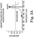
- Fig. 3A illustrates a preferred approach used by the present invention to identify pre-selected spectral wavelengths used to distinguish among the selected target substance(s) and/or background substance(s).
- Fig 3A shows how water can be distinguished from background spectral information using two spectral components.
- the target spectrum and background spectrum are simple and substantially different as in Fig. 3A the spectra need to be examined at only two wavelengths to easily detect the target substance.
- absorption spectral information can be examined at 760 nm and 980 nm. If the ratio (980 nm/760 nm) or other suitable characteristic(s) of the spectral response at these two wavelengths is greater than a threshold, then the pixel of captured image information providing that response corresponds to water. If the ratio is too low, no water is detected with respect to that pixel.
- spectral information for durum wheat, triticale, barley, and individual durum kernels is shown.
- spectral information at approximately 760 nm, 1100 nm, 1200 nm, 1300 nm, 1460 nm and 1650 nm any one of the substances can be identified from the captured image information.
- Spectral properties of the captured wavelengths e.g., ratios, sums, differences, averages, etc., can be analyzed to determine which of the materials is associated with a pixel in the image information. The assessment is accurate and fast. If computing power is fast enough, the results of an analysis can be computed and displayed in a fraction of a second even for images captured at higher resolutions, e.g., 16 megapixels or higher resolution.
- the target substance can be accurately detected with a relatively low number of spectral samples (2 and 6 wavelengths, respectively, in these examples).
- the present invention may also be practiced by gathering spectral information at a greater number of wavelengths, but when the use of a more limited number is effective, it is much more efficient and economical.
- the advance selection of the filter wavelengths in the present invention provides a significant advantage over conventional hyperspectral imaging systems in terms of the volume of data that must be acquired, stored and processed.
- a comparable multi-camera system with 3 wavelengths requires less than 1% of the data volume and processing effort when compared to a hyperspectral system having 310 spectral bins. While maintaining the same diagnostic power for many substances, this data savings, inherent in the present invention, can be used to greatly increase the spatial resolution for a multi-camera system having the same memory space and processor capability over its conventional hyperspectral counterpart.
- the selected wavelengths from block (23) are used to determine the corresponding filter elements (104) to be implemented as a filter array in the filter card (106).
- filter card 106 as shown includes an array of seven different filter elements 104. This indicates that for this particular target substance, spectral information at seven specific, different wavelengths are to be used to detect the target substance. For other target substances, the same, a greater or lesser number of filter elements 104 may be included in the array to accomplish detection.
- Each filter element 104 is used to selectively filter the spectral information captured by the system 10 so that system 10 can assess which portions (if any) of the captured image information generate spectral responses at the selected wavelengths to confirm that the captured image portion, e.g., each pixel of the image in some embodiments where pixel by pixel analysis is desired, indicates the presence of the target substance at that location of the captured image.
- each filter element 104 has a bandwidth effective to capture one of the corresponding, selected wavelengths to be used to detect the target substance. More desirably, the center wavelength of each filter element 104 is a selected wavelength determined in block 23.
- the bandwidth of each filter element 104 may be selected to allow system 10 to reliably detect and assess whether the specific spectral response of the target substance at that wavelength is detected. Selecting an appropriate bandwidth for each filter associated with each selected wavelength may be optimized as a tradeoff between a narrow bandwidth, which is more selective, and a wider bandwidth, which passes a greater quantity of light making the system 10 perform better under low light conditions. Balancing such concerns, a suitable bandwidth for each filter element 104 is typically up to 30 nm, or up to 20 nm, or up to 15 nm, or up to 10 nm, or up to 5 nm, or even specific wavelengths in many modes of practice. Often, a suitable bandwidth for each filter element 104 is typically in the range from 10 nm to 30 nm.
- a spectral filter element with a bandwidth of 10 nm wherein the bandwidth is centered at 500 nm.
- Such a filter element will selectively pass electromagnetic energy with a wavelength of 495 nm to 505 nm while substantially blocking electromagnetic energy having wavelengths above and below this range.
- Such a filter element is well suited for capturing image information at wavelengths of 495 to 505 nm so that system 10 can determine if any portions of the captured image information indicate the spectral response of the target substance in this wavelength range.
- system 10 selectively captures meaningful spectral information at several wavelengths to enhance the ability of system 10 to accurately detect the target substance.
- the filter elements might include the following:
- Block 25 involves the generation of one or more algorithms that can be used to assess the captured, selectively filtered image information to determine if the spectral information indicates the presence of the target substance from the anticipated background using the selected wavelengths identified in block 23 and the corresponding filter elements 104 that selectively capture image information at those wavelengths.
- algorithm methods include, but are not limited to, eigenvector, basis function, least squares, principle component analysis, ratios, differences, matched filter, neural networks, cross-correlation, multivariate analysis, and numerous classification methods.
- system 10 contemplated by blocks 21to 25 can be carried out for any number of additional target substances such that the resulting system 10 includes a plurality of spectral filter arrays and algorithms to detect a substantial library of target substances.
- System 10 can be configured to detect any target substance in the library simply by choosing the appropriate filter array and then using a suitable system interface to select the corresponding detection algorithm(s).
- the interface may be automated such that selection of a particular filter array causes system 10 automatically to implement the corresponding algorithmic analysis.
- the user could manually select the appropriate algorithm(s).
- the orientation of a filter array when integrated into system 10 may cause system 10 to automatically (or manually) select algorithm(s) corresponding to that orientation of the spectral filter array.
- blocks 21 to 25 may be part of a manufacturing process for system 10 where an inventory of one or more spectral filter cards and corresponding algorithm(s) for a variety of different detection applications is designed and sold as a package. It is also anticipated that a family of filter elements may be incorporated into a single filter card that contains subsets of filter elements, wherein each subset of the filter elements in the cards works to identify a different target substance.
- filter card including four filter elements 1 through 4, respectively.
- Application A may use filter elements 1, 2, and 3 on a four-element filter card, while application B may use filter elements 1, 3 and 4, while application C may use filter elements 2, 3, and 4.
- the combination of filter elements for multiple applications is dependent upon the spectral characteristics of the selected target substances and the desire of the user to have several applications readily available without the need to change filter cards.
- Another example of using a single filter card for multiple detection purposes might involve a three-application filter card designed for forensic investigators at a crime scene. Such a combination might include the selection of spectral filter elements to detect blood splatter, filter elements to detect semen, and filter elements to detect fluorescent dyes used to highlight fingerprints. Quite easily, the present invention could provide three different filter cards (and their associated software algorithms) for blood, semen, and fingerprints, respectively, wherein each filter card includes an array of filter elements suitable for selectively capturing the previously identified set of selected wavelengths that allow the corresponding target substance of interest to be identified from filtered image information.
- the present invention contemplates that a single filter array on a single filter card could be used to capture filtered image information for all three substances. This is efficient if the plurality of target substances at issue have one or more filter wavelengths in common. In this case, additional functions can be provided with only an incremental increase in the number of filter and camera elements. Under the described combination scenario, different filter elements within the same filter card could be used by the same or different algorithms to detect and locate each of the different target substances in the captured image information.
- the output could comprise a color-coded image that displays the locations of blood, semen and fingerprints at the crime scene or any combination thereof.
- a consumer example of a combination of applications on a single filter card for a busy parent of small children with a kitten as a pet might include a spectral filter group for detecting sunscreen (to assure complete coverage of children's skin at the beach), a filter group to detect cat urine stains (to quickly locate kitten 'accidents'), and a filter group for matching paint colors (to precisely match paint colors in the kitchen).
- Block 26 indicates the optional step to calibrate the system for individual variations in filter element and sensor element sensitivity. This step increases the accuracy of detection and is preferred.
- This function can be implemented as part of either the target algorithm design during manufacture of the system or later as part of the image capturing phase of using system 10.
- each filter element 104 may have a specific attenuation of light at its center frequency and across its bandwidth. This attenuation may be measured during manufacture and recorded in a database for each element 104 of a filter card 106.
- the specific filter card calibration can be looked up in this database, over the internet or otherwise, according to a specific filter card serial number or designation.
- a calibration, also stored in a database during manufacture, is possible for the sensor element(s) of the image capture array 111.
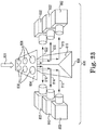
- Image capture array 111 also is referred to herein as a "multi-camera array 111" to indicate that component 111 is capable of capturing a plurality of filtered spectral images simultaneously when the image capturing elements 112 are aligned with corresponding filter elements 104 in card 106.
- each image capturing element 112 captures a corresponding, filtered image whose bandwidth is spectrally limited by the filter element 104 through which the filtered image is captured.
- each image capturing element 112 is associated with a single camera body 114, and these bodies 114 are stacked in an array suitable to align with the corresponding filter elements 104. In other modes of practice, multiple image capturing elements 112 may be incorporated into a common camera body.
- multi-camera still applies to a common body embodiment in the sense that “multi-camera” means that the system captures a plurality of images simultaneously regardless of the number of camera bodies involved.
- Fig 14 shows an alternative embodiment of a multi-camera array including a single camera body incorporating a plurality of image capturing elements for simultaneous image capture.
- multi-camera array also is used to refer to an "image capture array”.
- spectral filter array also may be referred to as a "multi-element spectral filter”.
- the camera sensor elements may be calibrated using any suitable technique.
- a multi-wavelength calibration is suitable either via a calibrated light source that changes wavelengths, or a standard, broadband light source using a calibrated filter card with filter elements at designated wavelengths and attenuations which permit an accurate interpolation across the entire spectral region for which the sensor is used.
- Both the filter elements and the camera sensor elements may also be recalibrated using the real-time processing system and an automated calibration system used in the field.
- Such an automated calibration system desirably has the traits described above and can automatically record the resulting calibration parameters within the memory of a smartphone, or other computing device to be used during operation of the system.
- the system 10 can rapidly capture and process filtered images simultaneously acquired from the multi-camera array 111 to provide any desired output to report the results of the detection.
- the system can indicate whether or not the target substance was detected.
- the system also may provide information showing the location of the target substance in the captured image information.
- the system may provide a color-coded output image that shows where the target substance is within the cumulative fields of view of the camera array.
- any motion of the target has less of an impact on detection accuracy as compared to instances in which images or scans are performed only sequentially.
- Simultaneous image capture makes the present invention very suitable for detection in environments with moving targets.
- Fig. 1 shows how system 10 is used to capture image information from a target surface 109 in Block 32 to allow system 10 to assess whether the target substance at issue is present in the target surface 109. Additionally, system 10 is used to capture the image information to allow system 10 to output the precise location(s) of the target substance, if present, in the target surface 109.
- the images are simultaneously acquired in step 32 from each image capturing element 112 (also referred to as a camera element herein) of the multi-camera array 112.
- Each image capturing element 112 is aligned with a corresponding filter element 104 so that such image capturing element 112 captures filtered images through the corresponding filter element 104.
- Each filtering element 104 has a bandwidth that is sensitive to a unique selected wavelength associated with the detection of the target substance. Therefore, each acquired image respectively includes information from only a unique, narrow region of the electromagnetic spectrum centered and limited by the filter element 104 through which the image was captured.
- the components of the multi-camera array occupy slightly different spatial positions relative to the target surface 109, it may be desirable in some modes of practice to more precisely align or register the captured images in optional block 33 such that corresponding pixels in each image represent the same point on the target surface 109. Once properly aligned, the images may be further processed to detect the target substance on the target surface.
- spatial image alignment or registration is the process of overlaying or aligning two or more images of generally the same scene taken from different spatial viewpoints.
- System 10 in fact, simultaneously captures a plurality of filtered images of substantially the same scene from a plurality of viewpoints.
- the separate images it is desirable for the separate images to be accurately aligned with each other such that corresponding portions of the target surface can be properly identified in each of the different images.
- having at least two cameras capturing images of the scene of interest from multiple viewpoints permits the present invention to acquire stereoscopic data. These data may be used to derive three-dimensional data about the target surface using stereoscopic image processing techniques known to those skilled in the art.
- optional block 28 it may be desirable in optional block 28 to properly identify the illumination that is present. This may be accomplished by examining the image intensities from various spectral imaging elements 112 with knowledge of their associated filter wavelengths, or it may be accomplished by energizing custom lighting with known spectral properties (i.e., LED, incandescent, sodium, neon, quartz halogen, ultraviolet, tungsten, fluorescent, compact fluorescent, infrared, near-infrared, mercury vapor, xenon, or laser sources). Once the illumination spectrum is known, the intensity of each acquired image may be normalized in optional block 34 to take the spectral features of the given illumination into account. A variation on the automated identification of the illumination source would include a user interface (i.e., software, switch or button) to manually identify the type of illumination as shown by optional block 27.
- a user interface i.e., software, switch or button
- system 10 uses the captured image information, optionally modified by processing such as alignment and normalization, to detect the presence of the target substance (if any) on the target surface 109.
- System 10 then generates an output that communicates the results of the evaluation.
- a wide variety of different outputs can be used.
- system 10 may output information indicative of whether the target substance was detected or not.
- Other output information may be in the form of an image of the field of view of the system 10 that shows the locations, if any, where the target substance is located. This is particularly useful in applications where the target substance or its characteristics are not easily visible to the naked eye.
- Other output may communicate other qualitative or quantitative information concerning the target substance.
- Figs. 4 Schematic
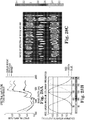
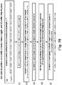
- Fig. 19B organic contaminants on stainless steel
- Fig. 20 poultry carcass
- Fig. 25E water
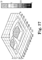
- Fig. 27 water
- Fig. 28C grains
- Fig. 32B road conditions
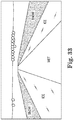
- Fig. 33 car vision
- Figs. 34B to 34D liquids
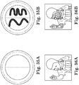
- Fig. 35B unsunscreen
- Fig. 36B unsunscreen
- Fig. 37 Fig. 37
- a displayed image may be formulated to show the spatial presence of the target substance as a solid color easily discerned from other parts of the display.
- the displayed image may be processed to indicate the presence of the target substance above a threshold level as a binary image mask. This mask is then used to force the associated pixels in the spatial orientation image to a fixed level.
- the colormap may be programmed to provide a grayscale color for all levels except the fixed level corresponding to the pixels related to the target substance.
- a displayed image may be formulated to show a quantitative amount of the target substance at locations within the target field of view.
- a binary target mask may first be derived as described for the 'presence' above. However, a further processing step introduces varying values in the 'presence' locations that represents the concentration or quantity of the target substance. The colormap is then derived to transform the variations in quantity into variations in color or color intensity.
- data used to generate the custom 'presence' and 'quantity' displays may be made available for analysis or export to another computing device.
- Fig. 1 shows an exemplary technique for generating a "presence" output in the form of a displayed image in which locations of the target substance in the displayed image are colored substantially differently from other portions of the image.
- the acquired images can be converted in block 37 into an output image 122 of the target surface 109 showing the locations 120 of the target substance on the image 122 .
- the matrix of pixels making up image 122 may be enhanced to more clearly show the locations of the target substance by color-coding the image.
- a suitable color map may be selected in optional block 36 and then applied in block 37 to output the color-coded image 122.
- the locations 120 of the target substance are shown as areas of a different color relative to the other portions of image 122.
- the color used to represent the locations of the target substance can be much brighter than the other colors in image 122 to make it easy to see the locations 120 in image 122.
- the image information can be evaluated at any desired resolution. For example, each pixel of the captured image information can be individually analyzed. This is a highly accurate way to identify not only that the target substance was detected but also to precisely indicate where the location(s) of the target substance is in the captured image information. In other modes of practice, the system 10 might analyze a plurality of pixels. This is an extremely accurate approach to detect the presence of the target substance in the image, but the location of the target substance is less precise than if each pixel is evaluated.
- the present invention can acquire images and display results at extremely fast rates.
- system 10 executes the necessary computations and processing steps to provide a displayed image as output within a time period from image capture that is less than the frame rate required for video imaging, typically 1/30 second.
- This allows the present invention to operate and display results at a video rate or higher.
- This is accomplished according to one illustrative approach by applying the algorithms of this invention to the simultaneously acquired, multi-camera images via a high-speed, image or signal processor. Since the images of this invention are all acquired simultaneously, this invention can accurately freeze motion within the field of view preserving relative positions of moving targets within the field of view, a feat impossible for competitive systems that sequentially apply filter elements in front of a single camera.
- This capability of the present invention provides an accurate, real-time record of a target that is moving.
- a variation on the above embodiment can provide a video playback rate using a slower processing system. Since the images are acquired and saved simultaneously, a slower processing system can be used to apply the algorithms of this invention in slower than real time. While the slower processing system does not process the data fast enough to keep up with the actual event, the fully-processed, final video record can be played back at a video (or higher) rate to accurately represent the original motion of the target.
- System 10 also is useful in any non-contact, application where an instantaneous chemical analysis of a remote surface is beneficial.
- system 10 can be mounted on dynamic platforms that move in the environment. Examples include land, air, and water-based vehicles.
- system 10 can be mounted on piloted or unmanned aircraft to capture aerial images of a region of interest. The captured images can be used on the aircraft and/or can be transmitted to a remote location, if desired.
- a key feature of system 10 is a multi-camera array capable of capturing a plurality of filtered images simultaneously.
- System 10 can simultaneously capture all spectral components needed for detection since all the spectral imaging elements 111 are optically aligned with corresponding filter elements 104 at the same time. Images may be captured simultaneously, providing advantages for high-speed imaging and imaging of moving targets.
- a detection image is an image acquired by a spectral imaging element 112 and its corresponding filter element 104. Each corresponding spectral imaging element 112 and its corresponding filter element 104 constitute a detection pair. Each detection pair has a selected wavelength sensitivity that is strategically influenced by the presence of the target substance.
- the filter element 104 of such a pair is selected to provide a wavelength sensitivity for detection of a unique wavelength at which the target substance has a known spectral response as determined in block 23.
- system 10 desirably includes at least one detection pair to capture at least one detection image representing a strategic wavelength useful to detect the target substance at issue.
- a spectral reference image is an image acquired by a detection pair with a selected wavelength sensitivity that is minimally influenced by the presence of the target substance.
- the spectral reference image is useful for evaluating illumination and establishing reference levels essential to detecting changes due to the target substance. As described further below with respect to water, such a wavelength also may be used to identify a target substance based upon the minimal spectral response at that wavelength.
- a spatial orientation image is an image that reasonably represents the spatial orientation of objects within the cumulative fields of view of the system 10 as viewed within the visible spectrum.
- the SOI may be acquired by an independent element of the system 10 or it may be a shared image also serving as a spectral reference or detection image.
- An output image (OI) 122 is an image that provides the output of the operational processing and that shows the derived information about the target substance.
- the output image includes a spatial orientation image, shown generally in grayscale except that the target substance information is displayed as a color-coded addition to the grayscale SOI in those places in the image where the target substance has been detected.
- system 10 may be adapted to a specific application via a set-up or design step that selects specific wavelengths that uniquely distinguish the spectrum of a target substance from the spectra of background substances.
- System 10 formulates a target algorithm that identifies the target substance from its spectral characteristics at a plurality of selected wavelengths.
- a multi-camera array is then implemented having elements that are sensitive to each of the selected wavelengths, respectively.
- the unique spectral sensitivity for each element of the multi-camera array is achieved via an interchangeable filter array with each filter element optically aligned with a corresponding element of the multi-camera array.
- Each element of the multi-filter array passes only one of the selected wavelengths.
- This structure converts the universal multi-camera array into a custom spectral analysis tool specifically designed to analyze the spectrum of the chosen target substance.
- the derived information regarding the target substance(s) has many useful applications.
- Fig. 4 schematically shows an alternative embodiment of a system 200 according to the present invention.
- System 200 includes camera body 202 incorporating a plurality of spectral imaging elements 204 that capture, encode, and store filtered images captured by system 200.
- a spectral imaging element 204 includes a lens or a combination of lenses that is optically coupled to media capable of chemically and/or electronically storing images transmitted by the lens or lenses to the media.
- Exemplary electronic media include sensors such as a charge-coupled device (CCD) or CMOS image sensor.
- CCD and CMOS sensors are commonly used in digital photography with a blocking filter to exclude wavelengths outside of the visible spectrum. A wider bandwidth with these economical sensors may be achieved in the present invention by removing or not installing these blocking filters.
- spectral imaging elements 204 may capture images using any suitable imaging methodology such as a single shot capture system.
- system 200 includes three spectral imaging elements 204.
- a filter array 206 comprising filter elements 208 is incorporated into system 200.
- the filter array 206 includes a filter element 208 for each spectral imaging element 204.
- one of the filter elements 208 has a spectral bandwidth of 420 nm to 430 nm that is well suited for detecting a spectral response at 425 nm, ⁇ 1 .
- a second of the filter elements 208 has a bandwidth of 570 nm to 580 nm that is well suited for detecting a spectral response at 575 nm, ⁇ 2 .
- the third filter element 208 has an optical bandwidth of 630 nm to 640 nm that is well suited for detecting a spectral response at 635 nm, ⁇ 3 .
- System 200 is being used to analyze whether a target substance having pre-determined spectral characteristics at 425 nm, 575 nm, and 630 nm might be present in a surface 212 and, if present, where the target substance is located.
- System 200 is aimed so that the spectral imaging elements 204 have a cumulative field of view 211 that encompasses surface 212 with multi-wavelength light 207 reflecting from the surface into spectral filter 206.
- system 200 has a resolution such that surface 212 constitutes a 3 x 3 array of pixels in the captured images.
- the pixels are labeled as pixels a through i, respectively. In actual practice, captured images will include thousands and even millions of pixels.
- System 200 is actuated to capture filtered images 214, 216, and 218.
- Captured image 214 is captured to assess the spectral response of each pixel at 425 nm, ⁇ 1.
- Captured image 216 is captured to assess the spectral response of each pixel at 575 nm, ⁇ 2.
- Captured image 218 is captured to assess the spectral response of each pixel at 635 nm, ⁇ 3.
- Each of the captured images 214, 216, and 218 is processed to align the 3 x 3 array of pixels in the captured images. For illustration purposes, each pixel of each captured image having a pre-defined spectral response associated with each targeted wavelength is marked.
- the target substance is deemed to be located in a particular pixel if that pixel in all the images is marked.
- System 200 then provides an output image 220 showing that the target substance was detected in the surface 212 at locations corresponding to pixels b, d, and e.
- System 230 includes a camera body 232 wirelessly linked to smartphone 233.
- Camera body 232 includes a plurality of image capturing elements 234 in a recess 236.
- Recess 236 is bounded by frame 238 that can be used to hold any one of interchangeable filter cards 240 from filter card library 242.
- Each filter card 240 includes a base 243 and a plurality of filter elements 244.
- some filter cards may have light sources 245, such as LED, installed for one or more wavelengths. For purposes of illustration, one such filter card 240 is being inserted into frame 238.
- each of the filter elements 244 on the card 240 optically aligns with a corresponding image capturing element 234.
- system 230 automatically identifies the filter card and selects an algorithm suitable for analyzing captured images to detect one or more target substances associated with that filter card 240. All of the filter cards 240 in library 242 are interchangeably installed into camera body 232 so that system 230 is easily configured to detect a wide variety of target substances corresponding to the filter cards 240 and corresponding algorithms.
- Smartphone 233 provides computing power, display for input and output, and an easy touch screen interface for system operations.
- the present invention is physically attached to smartphone 233 or other battery-powered mobile device such that the battery capacity within the present invention may be shared with the smartphone 233 or mobile device by connecting the power circuits of the devices or transferring energy via magnetic field link or other suitable coupling.
- System 230 can capture a plurality of filtered images (not shown) from a scene 246 and 293.
- the scene 293 includes target substances 295 and non-target substances 294.
- System 230 detects the differences in the spectral signatures of the substances 294 and 295 within the scene 293, and displays an output image showing the location of the target substances 295 in a different color 296 than the non-target substances 297 on the display 298 of the smartphone 233.
- the regions of the display that do not contain the target substance may be displayed in grayscale 297.
- System 230 allows specific wavelengths in a portion of the electromagnetic spectrum to be selected to uniquely identify the target substance at issue.
- Other illustrative applications of this invention may include medical imaging, crop analysis, sanitation, egg inspection, food processing, meat processing, vascular imaging, wound healing, skin cancer and tumor detection, urine analysis, moisture detection, building inspection, vegetation analysis, forensic detection of body fluids, manufacturing, pharmaceutical, nutraceutical, machine vision, mineral screening, sunscreen detection, estrus detection, pest control, hunting, and carpet stain detection.
- the ability to capture and evaluate selected wavelengths for different target substances is incorporated into the system via filter elements 244 of the spectral filter array included in card 240 and a custom target algorithm that evaluates captured image information to assess the spectral characteristics corresponding to those of the target substance.
- a new target substance may be detected by simply using a different, interchangeable spectral filter card 240 and a different target algorithm associated with the new card.
- Preferred features of system 230 include the use of a multi-camera array capable of simultaneous image acquisition, an interchangeable filter card, economical charge-coupled device (CCD) detectors (commonly used in digital cameras), calibration methods, high resolution, and displays with custom colormaps. These features help the present invention bring the analysis power of a remote-sensing satellite or hyperspectral imaging system to an economical, compact platform.
- CCD charge-coupled device
- the interchangeable filter cards 240 are an advantageous feature of system 230. Choosing among the different interchangeable filter cards 240 can quickly change the spectral characteristics of system 230 to detect different target substances. Individual filter elements 244 of the cards 240 are optically aligned with corresponding spectral imaging elements 234 to allow the acquisition of images that are sensitive to selected wavelengths useful for the accurate detection of a target substance. System 230 is easily configured to detect a different target substance simply by changing the filter card 240. Optionally, interchanging a new filter card 240 may cause system 230 to automatically select an associated target algorithm that has been specifically designed for the newly installed card and its corresponding target substance(s).
- the present invention may include an indication on the filter card, such as a model number or radio-frequency identification (RFID) tag or the like, that can be read electronically and used by the software of the present invention to automatically load the proper target algorithm and user interface from electronic memory storage resident within the device or located in memory accessible via a network connection, internet, cloud storage, or the like.
- RFID radio-frequency identification
- Embodiments of the present invention such as system 230 are advantageously derived from CCD-based camera systems, as these are widely available at low cost. These cameras often contain a visible spectrum filter that cuts out ultraviolet light and near infrared light, leaving the camera sensitive to the visible spectrum, approximately 400-700 nm. By removing (or not installing) this filter, the native sensitivity of the CCD sensor is expanded to approximately 300-1100 nm, i.e., from ultraviolet, through visible, to near infrared.
- incorporating a plurality of such CCD-based camera systems into a multi-camera array provides a low-cost, high-resolution imaging system suitable for analyzing spectral information at a plurality of selected wavelengths from a relatively wide wavelength range of approximately 300 to 1100 nm. This wavelength range is very suitable for detecting a wide range of target substances.
- CCD-based sensors or in addition to CCD-based sensors, other embodiments of the present invention may incorporate near infrared sensors that are sensitive to wavelengths longer than 1100 nm.
- system 230 can accommodate multiple selected wavelengths by using different kinds of sensors sensitive to different bands.
- one spectral imaging element sensitive to 600 nm may be implemented via a CMOS sensor.
- a second spectral imaging element sensitive to 800 nm may be implemented via a CCD sensor.
- a third array spectral imaging element sensitive to 1500 nm may be implemented via a GaAs-based sensor.
- system 230 incorporates and converts a common smartphone into a high-resolution, chemical imaging tool. Additionally, the small size and low-power requirements make the device ideally suited for mobile, aerial or stationary operation.
- the universal platform using a multi-camera array with interchangeable filter elements, permits the economies of high-volume manufacturing to be achieved for a base unit while still enabling a wide range of target substances to be detected by simply changing filter arrays.
- This invention may also be used with other computing devices such as tablet, mini-tablet, laptop and desktop computers.
- System 230 may be connected to any number of outside devices via connectivity standards common to smartphones and computing devices. Examples of such connectivity interfaces include, but are not limited to, Wi-Fi, Bluetooth, and/or numerous additional wireless standards.
- the wireless link may be replaced by any suitable wired link. Examples of wired links are selected from at least one of USB, Firewire, Ethernet, custom, proprietary, or a multitude of other wired standards.
- Natural sunlight provides a wide range of spectral output sufficient for most applications.
- artificial lighting might include incandescent lighting, fluorescent lighting, white LED lighting, compact fluorescent lighting or other light sources.
- Each of these artificial light sources provides a narrower output spectrum than natural sunlight.
- an incandescent light provides good illumination in the visible and near infrared, but provides a lower intensity in the ultraviolet spectrum.
- Fluorescent light provide visible and some ultraviolet illumination, but exhibits lower output in the near infrared region. Consequently, in some embodiments, system 230 may be used in combination with artificial light sources to help minimize the impact of different lighting situations upon detection accuracy.
- the interchangeable filter cards 240 optionally may contain LED or other illumination sources to more effectively and uniformly illuminate the field of view at the desired wavelengths.
- Power to the illumination source(s) may be obtained from the system 230 power supply, a separate power source, the base smartphone device, or even a battery supply incorporated into another component of system 230.
- Other auxiliary light sources may be selected from any number of light sources, such as incandescent, ultraviolet, near infrared, infrared, tungsten, mercury vapor, sunlight, Xenon, quartz halogen, compact fluorescent, high pressure sodium, and metal halide, or combinations of these.
- the auxiliary light source(s), if any, may be positioned in an advantageous position in order to illuminate the target field of view.
- the auxiliary light source(s), if any, may also be controlled by the present invention.
- the present invention includes an interchangeable spectral filter array on a module or card that can be placed in front of the multi-camera array.
- a new target algorithm to optimize the information obtained from the target substance can be readily installed either by manual or automated selection such as from an electronic directory resident within the device or located in memory accessible via a network connection, internet, cloud storage, or the like.
- the automated selection of the proper target algorithm may be triggered by an identification characteristic, such as a part number, on the newly installed filter card or module.
- the ability to detect additional target substances can be implemented quickly by examining the spectral characteristics of the new target substance, determining the necessary wavelengths and filter requirements, designing the new target algorithm, then using a new filter card and applying a new software algorithm to optimally extract information from the new target substance.
- an alternative embodiment of system 230 may be available having a relatively low number of image capturing elements 234 and spectral filter elements 244, for example 2 to 4 of such element pairs 234/244.
- Fig. 5A schematically illustrates such an embodiment having three spectral imaging elements 234. Such embodiments are capable of detecting information from a modest set of target substances.
- another embodiment of system 230 may be available having a higher number of spectral imaging elements 234, for example 5 to 12 spectral imaging elements. Such higher element embodiments will be capable of detecting information from a larger set of target substances.
- system 230 optionally includes a global positioning system (GPS) capability to geographically locate the images acquired.
- GPS global positioning system
- system 230 may use the GPS capability of the linked smartphone 233 or other suitable device.
- System 230 also may use the directional orientation capabilities of the linked smartphone 233 or other device to determine the elevation and direction that the camera array is aimed.
- system 230 may use GPS capabilities (or even manual entry) to locate crop vegetation data and orient these data on a map of the crop field.
- Crop features may be color coded or otherwise marked to indicate the health of the crop at various locations in the field.
- An accumulation of multiple images may be used to cover large portions of a crop or even an entire field.
- system 230 may incorporate electronically, tunable filter elements as all or part of one or more spectral filter arrays. Such tunable filter elements could replace all or part of the interchangeable filter cards 240 with an array of tunable filters for which the desired wavelengths may be electronically selected.
- any detection pair i.e., a particular filter element 244 and its corresponding image capturing element 234
- camera body 232 is shown as a separate hardware component that is mounted to smartphone 233.
- multi-camera capability may be incorporated directly into a smartphone, mobile device, tablet, mini-tablet, laptop computers, desktop computer or other computing device to provide a spectral imaging system of the present invention in a single, integrated device.
- the camera body 232 and smartphone 233 need not be physically coupled together. Instead, these may be operated at a distance from each other. Camera body 232 and smartphone 233 may communicate with each other in any suitable way such as by a wireless and/or wired connection. In such a configuration portions of the user interface and processing may be conveniently distributed in either part or allocated between both parts of the system.
- a color or grayscale camera integrated into the smartphone 233 may be used as part of the multi-camera array to provide a spatial orientation image when displaying detection results. For example, pixels of the spatial orientation image corresponding to the detected target substance can be highlighted via color or other indicia to show the precise locations of the target substance in the spatial orientation image.
- the camera system within the smartphone may be used as a viewfinder to aim the smartphone/multi-camera assembly, whereby the multi-camera system is used to acquire at least a portion of the captured images when the system is actuated.
- Spectral imaging systems of the present invention generally include two or more detection pairs of camera elements and corresponding spectral filter elements.
- Figs. 6, 7, 8 and 9 shows alternative embodiments of spectral imaging systems 260, 262, 264, and 266 of the present invention containing different numbers of detection pairs.
- System 260 includes multi-camera array 268 and filter array 270.
- System 260 is an example of an embodiment in which multi-camera array 268 includes two camera elements.
- Filter array 270 includes two filter elements, each aligning with a corresponding camera element.
- System 262 includes multi-camera array 272 and filter array 274.
- System 262 includes three detection pairs of camera elements and corresponding filter elements.
- System 264 includes multi-camera array 276 and filter array 278.
- System 264 includes seven detection pairs of camera elements and corresponding filter elements.
- System 266 includes multi-camera array 280 and filter array 282.
- System 266 includes 100 detection pairs of camera elements and corresponding filter elements.
- Fig. 10 shows another embodiment of a spectral imaging system 300 of the present invention in which spectral imaging arrays 302 and 304 are deployed at a plurality of different locations relative to a scene 314 being imaged.
- Spectral imaging array 302 includes multi-camera array 306 and filter array 308. Arrays 306 and 308 provide seven detection pairs for purposes of illustration.
- Spectral imaging array 304 includes multi-camera array 310 and filter array 312. Arrays 310 and 312 provide seven detection pairs for purposes of illustration.
- the two spectral imaging arrays 302 and 304 are positioned and aimed to examine two sides of a target (not shown) in scene 314.
- FIG. 11 shows a typical embodiment of a camera element 320 including lens assembly 322 and image sensor 324.
- a plurality of camera elements 320 are appropriately coupled to a common circuit board 326.
- Circuit board 326 may serve not only a plurality of camera elements but also other components of a spectral imaging system.
- each camera element 320 may incorporate its own dedicated circuit board.
- Lens assembly 322 and image sensor 324 may be mounted to circuit board 326 as shown or may be remote and coupled to board 326 by suitable wired or wireless interconnects.
- Fig. 12 shows an example of a multi-camera array 330 including 6 detection pairs.
- Array 330 includes six lens elements 332 and a corresponding array of six image sensors 334.
- the lens elements 332 and sensors 334 are mounted on a common circuit board 336.
- Fig. 13 shows an example of a spectral imaging system 350 whose detection capabilities are easily configured to detect a wide range of target substances.
- System 350 includes multi-camera array 351 and spectral filter array 358.
- Multi-camera array 351 includes a lens array of lens elements 352 and corresponding sensor array of sensors 354. Lens elements 352 and sensors 354 are coupled to circuit board 356.
- Filter array 358 includes card 362 incorporating filter elements 360. Each filter element 360 aligns with a corresponding lens element 352.
- Filter array 358 allows the multi-camera array 351 to be sensitive to capturing image information for a plurality of pre-determined wavelengths. The wavelengths are pre-selected so that the captured image information can be used to detect a target substance in the field of view of the system.
- Filter array 358 is easily interchanged with another filter array (not shown) of similar size and similar distribution of filter elements so that the other filter array aligns with the lens array.
- the spectral sensitivity and hence detection capabilities of the system 350 is expanded to encompass one or more other target substances.
- system 350 can be used to detect a vast number of target substances on demand.
- Fig. 14 shows an example of a spectral imaging system 380 including spectral imaging capabilities based on 120 detection pairs.
- System 380 includes spectral filter array 382, lens array 384, sensor array 386, and circuit board 396.
- Filter array 382 includes a 12 x 10 array of spectral filters 388 supported on substrate 390. Filter array 382 is interchangeable with other filter arrays (not shown) to expand the detection capabilities of system 380.
- Lens array 384 includes a 12 x 10 array of lens elements 394 that are optically aligned with corresponding filter elements 388.
- Sensor array 386 includes a 12 x 10 array of image sensors 398. The image sensors 398 are aligned with corresponding lens elements 394.
- the focusing of the images onto the image capture elements within the image capture array of the present invention may be accomplished in accordance with any suitable method(s). Examples include, but are not limited to, manual focus, numerous autofocus methods and focus methods under the control of program instructions.
- the focus of an individual detection pair, also referred to as a channel may be made independently or in coordination with one or more other channels.
- chromatic aberration is reduced or even avoided.
- Chromatic aberration is a common distortion of optical systems using lenses. This distortion plagues many conventional spectral imaging systems, such as those that use a spinning wheel of filter elements passing different wavelengths through a single lens and single camera lens system.
- the refractive index of lens materials varies with wavelength. This causes different wavelengths to be focused by a single lens at different distances from the lens.
- Camera manufacturers have designed various complex and expensive lens configurations to minimize this distortion with only marginal success over a broad range of wavelengths.
- the present invention solves this problem, even for simple, inexpensive lenses, since the present invention has a separate spectral channel for each selected wavelength.
- the optimal focus for each wavelength channel may be established and left in place while acquiring images. This permits the present invention to acquire images simultaneously and at video or faster frame rates. There is no need to sequentially refocus the system between each new wavelength acquisition, as is the case with conventional technologies.
- the present invention provides a solution to chromatic aberration by providing independent filter/camera channels (i.e., detection pairs) for each selected wavelength, permitting the distance from a lens to the focal plane to be adjusted independently to properly focus the spectral image on the image plane of the image capture sensor.
- independent filter/camera channels i.e., detection pairs
- an optional correcting lens may be included as part of the interchangeable spectral filter card, which corrects for deviation in focus due to the wavelength of the specific spectral filter element.
- an optional complex lens design that compensates for variations in wavelength and refraction index may be used as part of the present invention.
- individual lenses in an image capture array may be adapted, e.g., offset relative to a common image plane or have an altered curvature, etc., so that each lens in the array can capture and independently focus filtered light onto the image plane.
- Such an adaptation is desirable because each lens is intended to capture filtered light in a particular bandwidth that may require a different focal length than other bandwidth portions captured by other lenses in the array.
- an aperture of a lens/camera system is adjusted to increase the depth of field and reduce the chromatic aberration with minimal change in focus.
- the present invention may determine a focus for one channel and then compute a corresponding focus for additional channels based on the corresponding lens characteristics and the center wavelength of each corresponding spectral channel.
- the target algorithm may be formulated to take advantage of the characteristics of the target spectrum and the number of wavelengths available in a given product model. Some target substances may be easily detected or measured using only a few selected wavelengths, e.g., 3 wavelengths. More complex detection efforts, e.g., wherein a target substance has many spectral similarities to other features in the captured image information, may involve using a greater number of selected wavelengths, e.g., 10 or more, for detection.
- a simple ratio between the spectra sampled at two different wavelengths would be quite effective to detect water in a field of view of a spectral imaging system. If spectral information for a particular image pixel demonstrates such a ratio, the system may accurately conclude that water is present in the captured image at that pixel location. If the ratio is not demonstrated, there is no water detected at that pixel location. The system can perform this analysis for every pixel (or at another resolution, if desired) to comprehensively detect and map the location(s) of water throughout the captured image information. Even with this simple example, there is great flexibility in the selection of the wavelengths and the manner in which they are compared to identify or measure the target substance.
- one algorithm criterion may involve the identification of a narrow spectral peak in the spectrum of the target substance. This criterion is based on the principles that background substances are likely to have different peaks or broader transitions. To this end, two parameters are selected to optimize, namely the ratio between the spectra amplitudes and the separation of the wavelengths, with a narrow separation being preferred.
- the optimization surface, S( ⁇ i - ⁇ j ), may then be searched for a maximum.
- the wavelengths near that maximum are candidates to become the selected wavelengths for implementation in the multi-filter array and the target algorithm.
- a similar strategy may be used for more than two wavelengths. Numerous other formulas and methods may be useful to select a given number of wavelengths which may be used, in turn, to identify the chosen target substance.
- signal processing and statistical analysis methods may be used within a target algorithm to detect the target substance using spectral information at the selected wavelengths.
- Such methods include, but are not limited to, eigenvalue analysis, correlation analysis, principle component analysis, signal detection theory, pattern recognition, and multivariate analysis.
- An important feature of the present invention is the great freedom it provides to use a variety of effective target algorithms to accurately detect the target substance while still providing a platform that is economical, low-power, mobile, and high resolution.
- the target substance may be a pure substance.
- the target substance may be a mixture of one or more substances.
- the design of the target algorithm(s) can easily accommodate mixtures, because mixtures often exhibit spectral information that is different in a plurality of respects from the pure substances that make up the mixture.
- spectra may be acquired at various concentrations and analyzed to create corresponding target algorithm(s) capable of detecting and even providing quantitative information for mixture variations. This strategy may be used to advantage to actually measure the concentration of a target substance by evaluating the spectra at the selected wavelengths for each level of concentration.
- One application of this technique is to remotely and noninvasively measure moisture content in any number of substances such as soil, sand, grain, cereal, vegetation, feed, or wall material.
- An analysis of the spectra in the manner described for mixtures can also be used to evaluate the purity of a target substance or determine what impurities may be present.
- the present invention may be used to detect not only the presence of a target substance in a field of view but also to measure a quantity of the target substance within the field of view when spectral characteristics vary based on quantity. While a presence may be accurately detected using an accumulation of nominal values for filter attenuation, sensor variations, and light source variations, it may be advantageous to use an in-frame reference surface to calibrate these parameters across the formulation range of interest when making quantitative measurements.
- the in-frame reference may be used as part of a calibration procedure to quantify the concentration of the target substance.
- the spectral imaging system can use that information to calibrate the images captured with the in-frame reference in the field of view. For example, a certain ratio between peaks at two or more wavelengths may indicate a concentration of 10.0%, whereas another ratio might indicate a concentration of 25.0%, etc. This allows quantitative information to be determined with great accuracy.
- System calibration may be achieved via a number of methods.
- One such method is a cumulative calibration factor computed from individual calibration factors determined for each system component such as illumination intensity, filter attenuation, lens attenuation, and image capture sensor sensitivity.
- the overall system calibration is the cumulative product of the individual component calibration factors.
- Another method of calibration involves the use of an in-frame reference with known reflective properties on its surface. The in-frame reference method permits the entire system to be calibrated as a whole and avoids a possible accumulation of errors which may occur with the cumulative calibration factor method.
- the optimal calibration method for a given application depends on the required accuracy for that specific application and the cost or complexity of the calibration method.
- one component calibration is for illumination.
- An exemplary method to obtain a calibration for variations in illumination provides for the image data at each selected wavelength to be normalized to account for variations in illumination near that particular wavelength. In practical effect, this may be described as a multiplication by an illumination normalization factor, k illum . This permits an accurate comparison of the spectrum of the target substance at the selected wavelength without undue influence from variations in the illuminating source across the spectrum.
- an illumination normalization factor, k illum may be computed at each selected wavelength to remove the spectral response introduced by the illumination that is independent from the spectrum of the target substance.
- the illumination normalization factor, k illum as a function of wavelength, ⁇ , may be expressed as the reciprocal of the illumination curve, I( ⁇ ) , at each wavelength.
- k illum ⁇ i 1.0 I ⁇ t for non ⁇ zero I ⁇ i
- Illumination curves may be selected from a database list of generic illumination sources such as sunlight, incandescent light, fluorescent light or more specific light sources such as "a 60-watt, soft white GE light bulb” or “tungsten lamp, model 6315 1000W QTH Lamp3.” These illumination curves may reside in a memory base such as, local memory of the present invention, local memory of the associated mobile device, or an on-line or “cloud” database to which the device has access via the internet or other means. In any of these cases, the illumination source data will be such that the relative illumination intensity may be determined at the specific wavelength of a given camera/filter element.
- generic illumination sources such as sunlight, incandescent light, fluorescent light or more specific light sources such as "a 60-watt, soft white GE light bulb” or “tungsten lamp, model 6315 1000W QTH Lamp3.”
- These illumination curves may reside in a memory base such as, local memory of the present invention, local memory of the associated mobile device, or an on-line or “cloud” database to which the device has access via
- another component calibration is for sensor sensitivity.
- An exemplary method to obtain a calibration for variations in sensor sensitivity provides for the image data near each selected wavelength to be normalized according to the sensor spectral response via multiplication by a sensor normalization factor, k sensor ( ⁇ i ), where ⁇ i is the ith wavelength used to define the target substance (with other parameters at known levels or already normalized). This permits an accurate comparison of the spectrum of the target substance at each of the selected wavelengths.
- a sensor normalization factor, k sensor ( ⁇ i ) may be computed at each selected wavelength to remove the sensor's spectral response from the evaluation of the target substance spectrum.
- sensitivity at two wavelengths 550 nm and 980 nm, respectively, are used to demonstrate the suggested normalization. These wavelengths are shown in Fig.41 .
- S 550 0.620 at 550 nm
- S 980 0.818 at 980 nm k sensor
- the sensor normalization factor, k sensor ( ⁇ ) as a function of wavelength, ⁇ , may be expressed as the reciprocal of the sensor sensitivity curve, S( ⁇ ), at each wavelength.
- k sensor ⁇ i 1.0 S ⁇ i for n o n - zero S ⁇ i
- the sensor response curve may be determined for each individual sensor device as part of the manufacturing process where that sensor curve is stored in a memory base, such as a device memory or may also be acquired by looking up an identification number for the device in an on-line or "cloud" database to which the device has access via the internet or other communication system.
- the sensor sensitivity data will be such that the relative sensor sensitivity may be determined at the specific wavelength of a given camera/filter element.
- the sensor sensitivity curve may be re-measured and recorded in a memory base such as, local memory, an on-line database, or a 'cloud' database and made available for calibration purposes. This recalibration of the device may be performed at regular intervals determined by the aging characteristics of the sensor.
- a filter normalization may be practiced that uses the filter gain, A filter , for each filter element.
- a 550 0.85 at 550 nm
- a 980 1.25
- the system calibration may be accomplished via an accumulation of normalization factors specified for each component in the system. This method is represented by the formula below for each spectral component.
- I cal ⁇ i k illum ⁇ i K sensor ⁇ i k filter ⁇ i I measured ⁇ i where the normalization factors, k ilium , k sensor, and k filter , are as described above;
- I measured ( ⁇ i ) is the uncalibrated intensity as measured at wavelength, ⁇ i ;
- I cal ( ⁇ i ) is the calibrated intensity for the target surface at the designated wavelength, ⁇ i .
- the filter normalization factor, k filter ( ⁇ ), as a function of wavelength, ⁇ may be expressed as the reciprocal of the filter gain, A filter ( ⁇ ), at each wavelength.
- k filter ⁇ i 1.0 A ⁇ i for n o n - zero A ⁇ i
- the cumulative calibration method may be advantageous for the detection of the presence of a target substance.
- the normalization factors for the illumination source, sensor sensitivity, and filter element gain may be retrieved from calibration data stored in memory.
- the illumination source may be selected from a list of typical sources which may be encountered such as sunlight, incandescent, fluorescent, tungsten, LED, or other light sources with commonly known spectral emissions.
- the sensor calibration may be obtained by an initial calibration at the time of manufacture, periodically updated as needed.
- the filter efficiency is available as a specification for each individual filter element, perhaps confirmed at the time of manufacture.
- an in-frame reference may be used to more precisely calibrate all system components at once.
- Such a calibration may use a single surface (or multiple surfaces), broadband, in-frame reference (or reflector) with known spectral characteristics.
- the measured spectral amplitudes may be normalized according to variations in reference levels and then the formulas above may be applied.
- the in-frame reference calibration method has the potential for greater system precision since undue accumulation of normalization factor errors is avoided by accounting for the normalization factors all at once. This method is particularly advantageous for applications where a quantitative measurement of the target substance is desired.
- One solution is to link the optical and spectral features of the camera array such that they all change in unison.
- Another solution is to fix the camera optics with the same parameters.
- a third solution is to permit each element to optimize certain parameters which are mathematically accounted for within the calibration or measurement algorithms. Throughout the normalization and calibration process it is desirable to account for variations in intensity such that the relative spectral amplitudes at various wavelengths are maintained.
- the present invention may be used in reflectance and/or transmission modes.
- reflectance mode the light reflects from the target surface and is detected by the system components.
- transmission mode the light is transmitted through the target surface and then continues on to be detected by the sensors within the system.
- Subjects such as vegetation, minerals, fresh produce, and fluorescent paints typically are viewed in the reflectance mode.
- Subjects such as liquids or gasses are often viewed in a transmission mode.
- Some substance may be viewed in either mode individually or in both modes simultaneously, such as mammalian skin and tissue. It is important to use the proper spectrum for reflectance or transmission (absorption) modes, respectively, because transmission and reflectance spectra for a particular substance may not be the same. For example, spectral peaks in a transmission spectrum may be at different wavelengths and/or have different amplitudes than spectral peaks in a reflectance spectrum.
- One embodiment of the present invention uses a permanent, stationary geometry of the multi-camera array.
- all elements of the multi-camera array are spatially fixed with respect to each other (such as by permanent mounting each camera element on the same circuit board).
- a registration between images from various camera elements can be determined at the time of manufacture.
- a reference target surface with an advantageous target subject matter may be used to derive a registration formula to fully register the images from various camera elements.
- the registration or alignment of the various images from the individual camera elements can be empirically determined at the time of manufacture and an alignment formula stored in digital memory. Such an alignment formula can then be recalled as needed throughout the lifetime of the product.
- An advantageous alignment target used to optimally register or align the individual images, may be selected or created to have similar features visible to all camera elements regardless of their spectral sensitivity. Using this alignment target, images can be acquired that are ideal for generating an alignment mapping function. An alignment mapping function can be generated for each camera element within the array, transforming them to a common or reference axis.
- Another embodiment of the present invention may use focus or zoom capability.
- a stationary mapping function is used with an added mathematical formula to compensate for a change in focus or zoom.
- Such an additional formula will include an image scaling component to account for a change in image size due to focus or zoom capability.
- the present invention provides a common platform capable of performing spectral image analysis for numerous, diverse detection and analysis applications.
- Exemplary applications include, but are not limited to, chemical composition analysis, water and moisture detection, water analysis, crop analysis, vegetation identification, vegetation mapping and infestation tracking, soil analysis, disturbed soil analysis, cranberry analysis, inspection of fruits and vegetables, locating missing persons, inspection of nuts, seeds, legumes and grains, robotic harvesting of fresh produce, biofilm detection, hand washing, food safety and processing, infection control, egg inspection, bird vision, forensics and criminology (e.g., detection of fingerprints, urine, blood, semen, hair, and the like), vascular imaging, diabetic foot perfusion, peripheral vascular disease, wound healing, feedback for cardiopulmonary resuscitation (CPR), cardiovascular risk assessment via a reactive hyperemia protocol, surgical tool inspection, surgical tool to indicate vascular clamping, lymphatic imaging and surgery, evaluating peripheral artery disease (PAD), breast and other cancer detection, medical imaging, medical diagnostic information automatically linked to an individual subject, veterinary and human applications, estrus
- the present invention relates to a method to acquire simultaneous images in order to analyze the chemical composition of a target surface within a field of view.
- the present invention relates to a method to derive information about water within a target field of view.
- the selected wavelengths might be one wavelength in which water is absorbed, such as 980 nm, and one wavelength in which water exhibits little absorption, such as 766 nm.
- Filter elements would contain bandpass filters for each of the selected wavelengths. After image alignment, a simple ratio of image intensities for corresponding pixels would yield an indication of the presence of water.
- moisture may be detected by comparing image intensities at two or more different wavelengths where the wavelengths are selected by an analysis of the spectral reflectance properties of moisture. After image alignment, the presence of moisture may be determined by the ratio of image intensities at the different wavelengths. Ratios greater than a given threshold could be indicative of the presence of moisture.
- the ratios described above for the detection of moisture may be calibrated via an in-frame reference surface in order to calibrate a given ratio value with a given percentage of moisture.
- Such a calibration may be used to determine a quantity of moisture present within the target surface.
- Such applications are valuable for measuring the moisture content of many substances, such as soil, cereal, food products, meat, snow, crops, vegetation, sheet rock, concrete, chemical products, frac sand, building construction, and minerals.
- the present invention relates to a method to analyze substances present in water.
- the spectral absorption band of water near 980 nm is narrow. This characteristic permits the identification of water with a filter element sensitive near 980 nm. Adjacent bands, outside of the water absorption band, are available to detect impurities, contaminants or formulations within the water. Examples of such uses include but are not limited to, pollution detection, on-site water analysis, aerial inspection of water quality, beverage processing, wastewater treatment, drinking water treatment, biosecurity at reservoirs, toxicity analyses, presence of organic material, presence of organisms, groundwater analysis and underwater exploration or mining.
- the present invention relates to a method to analyze a crop.
- the multi-camera array is aimed at a crop in order to derive information regarding the condition of the crop.
- This may include, but is not limited to, a crop condition such as nitrogen content, chlorophyll content, crop maturity, moisture content, disease state, insect infestation, fungus infestation, mold content, mildew content, weed content, plant maturity, harvest readiness, and fertilizer effectiveness.
- Fig. 15 illustrates the use of a spectral imaging system 400 of the present invention to analyze a crop 402 within a field of view 404.
- System 400 includes an image capture array 406 including a trio of image capture elements 408.
- System 400 also includes a filter card 410 including spectral filter array 412 that includes a trio of filter elements 414.
- the filter elements 414 are selected to be sensitive to the desired crop characteristics.
- filter elements 414 optically align with image capture elements 408 to allow each of the image capture elements 408 to capture an independent, filtered image of crop 402.
- System 400 may further include a smartphone (not shown) integrated with image capture array 406 and spectral filter array 412.
- the spectral imaging system 400 is positioned at an elevation sufficient to view at least a portion of the surface of crop 402 within a field of view 404.
- a corresponding target algorithm is provided to analyze the acquired spectral images and compute the desired crop information.
- Crop data acquired via system 400 in Fig. 15 may be communicated to any number of outside devices via connectivity standards common to smartphones and computing devices.
- connectivity interfaces include, but are not limited to, Wi-Fi, Bluetooth, and/or numerous additional wireless standards.
- the wireless link may be replaced by any suitable wired link. Examples of wired links are selected from at least one of USB, Firewire, Ethernet, custom, proprietary, or a multitude of other wired standards.
- Positioning and aiming the system 400 at the crop 402 may be accomplished in a variety of ways, including one or more of securing the invention within or on an aerial apparatus such as a commercial aircraft, private aircraft, glider, satellite, spacecraft, unmanned aerial vehicle, remote control aircraft, drone, blimp, lighter than air aircraft, manned balloon, weather balloon, projectile, rocket, personal air vehicle, paraglider, kite, or extraterrestrial aircraft; attaching the invention to a flying animal such as a bird or bat; placing the invention in the possession of a skydiver deployed over the crop; attachment to a pole, building, greenhouse, hill, mountain, tree, crane, bridge, overpass, or other permanent, semi-permanent, or temporary structure; attachment to a water tower, cell phone tower, or electrical tower; photographic tripod, mechanical fixture or similar apparatus; handheld or attached to a human; attached to a person via a mechanism, such as a head strap or chest strap; attached to or held by an animal; attached to or held by a robot; attached to a ground-based
- positions are also suitable for other applications where an elevated position may be advantageous to capture images of a scene for detection of a desired target substance.
- the present invention contains geographical coordinates for each set of images representing a portion of the field of view such that the images and data derived from the images may be assembled into a contiguous collage representing a larger portion of the entire crop field than is contained in any single image set.
- These geographical coordinates may be embedded in the image data, as is presently done via geo-tagging protocols, or organized in an independent data base.
- This invention may be applied to any crop that exhibits a spectral response that can be characterized by the spectral amplitudes at a discrete number of wavelengths.
- crops include corn, soybean, wheat, rice, cotton, cranberries, grapes, rye, sorghum, canola, rape seed, peas, sugar beets, oats, alfalfa, sugar cane, tomatoes, potatoes, edible beans, coffee, oranges, grapefruits, apples, nuts, peanuts, legumes, strawberries, blueberries, blackberries, onions, tobacco, peppers, spinach, broccoli, carrots, grass, brome, lupines, and avocado.
- Crop analysis may include, but is not limited to, soil analysis, soil analysis for the purpose of fertilizer distribution, growth tracking, plant maturity analysis, insect infestation, disease, nutrient content, stress levels, mold detection, mildew detection, weed analysis, crop dusting, harvest readiness, and the like.
- the present invention may be used to detect the signature of a specific crop for the purpose of analyzing the percentages of crop types in a given region.
- the present invention may be used to detect the signature of a specific illegal crop, such as marijuana, opium poppy (heroine) or coca (cocaine).
- a specific illegal crop such as marijuana, opium poppy (heroine) or coca (cocaine).
- Such use of the present invention may benefit law enforcement when used for aerial inspection of a given region or for illicit crop documentation in a handheld device.
- farmers may inspect their fields for unauthorized illegal crops planted in their fields, a practice commonly used by 'guerrilla' growers of illegal crops.
- the present invention is particularly well suited for this application in that it has the analysis power of conventional hyperspectral imaging at a great reduction in cost, and a significant increase in resolution over competitive hyperspectral imaging systems.
- the increase in resolution permits law enforcement to conduct surveillance from higher altitudes.
- a higher surveillance altitude reduces the risk from retaliatory shootings by illegal growers.
- a higher altitude, above 500 feet also minimizes court challenges for violation of privacy, sometimes encountered by law enforcement when they conduct
- Fig. 16 shows examples of spectra for healthy vegetation, unhealthy vegetation and soil.
- Three wavelengths (A, B, and C) are shown which enable the discrimination between the conditions.
- detecting information at these three wavelengths is enabled by using three camera and filter elements with a filter sensitivity centered around each of the designated wavelengths.
- it is possible to determine if a given pixel represents soil or vegetation by computing the ratio of wavelength C to wavelength B, C/B.
- Those pixels with a C/B ratio above threshold i.e., 2.0
- those pixels with a lower C/B value represent soil pixels. Only those pixels representing vegetation need be analyzed for vegetation health.
- the present invention relates to a method of identifying specific species of vegetation within the field of view. This application goes beyond the crop identification described above.
- Various species of vegetation have different spectral responses, making it is possible to identify many plant species via an analysis of their spectral response. Examples include, but are not limited to, tree species identification in a forest, crop species identification in an agricultural region, and grassland species documentation.
- the present invention relates to a method to identify genetically modified organisms (GMO) where the genetic modification causes a change in the target spectrum as related to the unmodified organism (i.e., GMO corn or wheat detection).
- GMO genetically modified organisms
- the present invention relates to a method to map a specific species of vegetation.
- the present invention may acquire aerial data indicating the location of various tree species within a forested, rural, urban or suburban setting.
- the present invention relates to a method to map a specific species of vegetation for the purpose of pest control.
- the present invention may acquire aerial data indicating the location of various tree species within a forested, rural, urban or suburban setting which are susceptible to infestation. For example, the location of ash trees may be determined which are susceptible to infestation by the Emerald Ash Borer beetle.
- the present invention relates to a method to track pest infestation within a specific species of vegetation.
- the present invention may acquire aerial data indicating the location of ash trees which are susceptible to the Emerald Ash Borer beetle and further analyze these data to identify damage to these same ash trees indicative of actual infestation. This is possible because the spectral characteristics of damaged trees would be distinct from that of healthy trees.
- the present invention relates to a method to analyze soil.
- the spectra of various soils may be evaluated to determine the selected wavelengths that distinguish between the soil types of interest. Filter elements are then chosen that are sensitive to these selected wavelengths.
- the present invention relates to a method to analyze the soil in preparation for crop planting and selection of fertilizer nutrients and dosage.
- the present invention relates to a method to detect disturbed soil.
- the soil analysis capability described herein may be applied to a region of soil within the field of view.
- the target soil area is analyzed. Any digging in the soil is likely to leave traces, or large amounts of soil that was originally positioned at a depth below the surface.
- This variation in surface soil composition can be detected with the present invention and highlighted on a display of the soil analysis. Unnatural soil discontinuities may automatically be flagged as possible disturbed soil.
- Disturbed soil detection may include, but are not limited to: the detection of dangerous devices, at or below the soil surface, which are intended to harm nearby subjects; the detection of underground tunnels; the location of shallow graves or buried objects; the location of archeological artifacts and structures from past civilizations; and the early detection of illegal drug cultivation. Disturbed soil detection may also be useful in the management practices of mining, agriculture, and construction.
- Cranberries are a valuable crop for which the present invention has particular importance. While the total acreage of cranberries planted in the U.S. is a small fraction of other crops such as corn, soybeans or wheat, the per acre value of cranberries is much greater. The 2013 cranberry revenue was reported to be $9566 per acre in comparison to $960, $536 and $468 per acre for corn, soybeans and wheat, respectively. (See USDA Noncitrus Fruits and Nuts, 2012 Preliminary Summary, January 1, 2013). Due to stringent wetland laws, cranberry growers find it difficult to expand their acreage to meet increasing demand for their product. Therefore, it is advantageous for cranberry growers to increase current crop yield in existing cranberry beds.
- the present invention relates to a method to map cranberry fields for soil analysis, maturity tracking, disease detection, weed management, and harvest readiness.
- the high resolution of the present invention makes the present invention attractive where the lower resolution of conventional satellite and other conventional, remote sensing technologies fall short.
- the present invention relates to a method to integrate a telephoto lenses into one or more spectral imaging element of a camera array.
- a crop field can be scanned with even greater resolution.
- the use of telephoto lenses on the camera elements can be beneficial in many applications other than crop scanning where high resolution scanning from a distance is desired.
- the present invention relates to a method to screen the harvested berries.
- Cranberries typically reach receiving stations with various grades of berry and numerous contaminants mixed with the product. Most cranberries are harvested by flooding the fields, vibrating the berries from the vines, and corralling the berries with floating booms towards the waiting harvest machines along the edge of the flooded field. The harvested cranberries may be white (unripe) and various shades of red. Rotten or bruised berries are also present. Since cranberry beds are sometimes adjacent to roadways, highway litter may end up at the berry processing plant in the form or paper, plastic, cigarette butts, and even metal particles embedded in the berries.
- the present invention can provide a low-cost, high-resolution solution to the sorting needs of the cranberry industry.
- the present invention relates to a method to provide a pre-screening system positioned adjacent to the cranberry fields during harvest that is low-cost, portable and of high-resolution.
- This pre-screening system would screen and remove defective berries and contaminants before loading on trucks for transport.
- the present invention relates to a method to inspect produce, such as fruits and vegetables, for contaminants within a quantity of the produce or on the surface of the produce.
- Spectra of the desired fruit or vegetable are acquired and compared with acquired spectra of likely contaminants. Selected wavelengths of these spectra are analyzed as described herein to determine the presence of contaminants within a quantity of the produce or on the surface of the produce. This information may be provided in real-time to automated sorting equipment to remove the contaminant from the good produce.
- the present invention relates to a method to inspect produce, such as fruits and vegetables, for quality, such as ripeness, maturity, bruising, rotten spots, mold, mildew or other imperfections.
- Spectra of the ideal produce are analyzed along with spectra of each imperfection. Selected wavelengths of these spectra are analyzed as described herein to determine the presence of produce imperfections. This information may be provided in real-time to automated sorting equipment to remove the imperfect item. In a similar manner various grades of the produce may be identified and sorted accordingly.
- the present invention relates to a method to inspect nuts, seeds, legumes and grains for contaminants within a quantity of the product or on the surface of the product.
- Spectra of the desired nut, seed, legume or grain are acquired and compared with acquired spectra of likely contaminants. Suitable wavelengths of these spectra are analyzed as described herein to determine the presence of contaminants within a quantity of the product or on the surface of the product. This information may be provided in real-time to automated sorting equipment to remove the contaminant from the good product.
- the present invention relates to a method to inspect nuts, seeds, legumes and grains, such as peanuts, walnuts, cashews, pecans, almonds, hazelnuts, chestnuts, acorns, pistachios, Brazil nuts, beechnuts, sunflower seeds, rice, pine nuts, ginkgo nuts, bunya nuts, macadamia nuts, garden or crop seeds, grass seed, wheat, rye, corn, soybean, barley, sorghum, canola, rape seed, oats, beans, and coffee, for quality, such as ripeness, maturity, bruising, rotten spots, mold, mildew or other imperfections.
- nuts, seeds, legumes and grains such as peanuts, walnuts, cashews, pecans, almonds, hazelnuts, chestnuts, acorns, pistachios, Brazil nuts, beechnuts, sunflower seeds, rice, pine nuts, ginkgo nuts, bunya nuts, macadamia nuts
- Spectra of the ideal produce are analyzed along with spectra of each imperfection. Selected wavelengths of these spectra are analyzed as described herein to determine the presence of produce imperfections. This information may be provided in real-time to automated sorting equipment to remove the imperfect item. In a similar manner various grades of the produce may be identified and sorted accordingly.
- Robots have been developed to harvest delicate fresh produce crops.
- present machine vision technologies do not have the ability to effectively distinguish between ripe and unripe fruits and vegetables, nor can they reliably identify leaves, stems and branches.
- the present invention fills a serious need that exists for an economical, mobile, imaging system to provide the ability to reliably select ripe fruits and vegetables, as well as exclude leaves, stems and branches.
- the present invention relates to a method to provide a machine vision tool that can distinguish between ripe and unripe fruits and vegetables. It can also differentiate between produce, leaves, stems and branches. By analyzing the spectra of each item the robot is likely to encounter, it becomes possible to determine the spatial position of each item within the robot's field of view.
- the filter card can be designed to provide each camera element with the appropriate wavelengths to identify the desired produce components.
- the low cost and high resolution of the present invention are advantageous for this application.
- the much lower data volumes of many embodiments of the present invention also facilitates easier real-time processing.
- the present invention relates to a method to provide the above features as a system that is not mobile, but stationary.
- a biofilm is any group of microorganisms on a surface. These adherent cells are frequently embedded within a self-produced matrix of extracellular polymeric substance (EPS). Biofilms may form on living and non-living surfaces and can be prevalent in many environments, such as, natural, industrial, agricultural and hospital settings. Biofilm EPS, often referred to in the common vernacular as slime, often is a conglomeration of extracellular DNA, proteins, and polysaccharides.
- the present invention relates to a method to detect a target substance that is a specific biofilm on a surface.
- a representative biofilm include films generated by microorganisms such as E. Coli or Salmonella.
- a characteristic spectrum of the specific biofilm is obtained by conventional hyperspectral imaging methods or other spectral means.
- specific selected wavelengths are determined that identify the desired spectra. Filter elements passing the selected wavelengths are incorporated into the elements of the spectral filter array.
- a target algorithm is established to reliably detect the chosen target substance.
- the present invention acquires and processes a number of spectral images as described herein. Finally, custom color displays may be generated to highlight the presence of a given biofilm on a surface within the field of view of the system.
- the present invention may be used as part of a sanitation process for inanimate surfaces to identify the presence of biofilms before, during or after sanitation of a surface in areas such as food services, food processing, meat processing, hospitals, clinics or any location where contamination by microorganisms is a concern.
- the present invention may also be used to identify the presence of biofilms on biological surfaces such as skin, dental surfaces, intestinal surfaces, endoarterial surfaces or any other biological surface.
- Hand washing is a vital component for any food safety program in such places as restaurants, fast food facilities, food preparation businesses, and food processing facilities. Historically, compliance was largely dependent upon training and the integrity of the individual employee. Even the use of food processing gloves does not assure sanitation unless the gloves are changed at appropriate intervals to avoid passing contaminants on the outside of the gloves. Recently, video cameras have been added as an enforcement tool which can confirm hand washing actions, but not results.
- the present invention relates to a method to improve hand washing efficacy as part of a food safety program.
- the present invention may be designed to directly inspect the hands and alarm if contaminants are detected. In this manner, the present invention becomes a direct measurement tool to detect contaminants that impact food safety, strengthening the present strategies used for food safety.
- Hand washing is also a vital component for infection control programs in hospitals and medical clinics.
- compliance is largely dependent upon the training and the integrity of the individual medical employee.
- the present invention relates to a method to improve hand washing efficacy as part of an infection control program.
- the present invention may be designed to directly inspect the hands and alarm if contaminants are detected.
- Common contaminants that are handled by medical personnel include blood, feces, urine, and bodily fluids, which are all readily detectible via the present invention.
- the present invention becomes a direct measurement tool to detect contaminants that impact the spread of infection within a medical facility.
- Hyperspectral imaging has been shown to be valuable in screening eggs for early fertilization detection (0-3 days), blood spots, bad egg (bacteria), and air sack size using a hyperspectral camera sensitive to wavelengths from 400-900 nm. It was found not to be accurate for crack detection. "The hyperspectral imaging system appears capable of detecting developing hatching eggs by Day 3 of incubation at a 91% rate for white shell eggs, and an 83% rate for brown shell eggs. Blood spots in table eggs can readily be detected with at least a 90% accuracy rate. Cracked shells are difficult for the hyperspectral system to detect under typical conditions.” D. P. Smith, K. C. Lawrence, and G. W.
- the application of the present invention to egg inspection offers significant advantages over the conventional hyperspectral imaging systems.
- the cost of a conventional hyperspectral system approximately $150,000, may be reduced to under $5000 using principles of the present invention.
- the present invention is also capable of vastly improved resolution over a conventional hyperspectral imaging system.
- the improved resolution of the present invention is likely to improve the diagnostic performance for detecting the small, dendritic shape of blood spots within the egg and may even be capable of detecting cracks in the shell, a critical function that the conventional hyperspectral system cannot achieve.
- the size, mobility and weight of the present invention are also key advantages over the conventional hyperspectral imaging system.
- the present invention relates to a method to inspect table eggs for defects such as blood spots, bacterial contamination and cracks.
- the present invention relates to a method to evaluate hatching eggs for fertility and infertility, bacterial contamination, proper development, and cracks.
- the present invention relates to a method to inspect eggs for fecal contamination on the surface of the shell since avian feces may contain Salmonella and E. Coli.
- the presence of feces on the egg surface may be a serious contaminant.
- the spectra of feces and the spectra of egg shell are analyzed to select the wavelengths to best discriminate between the two materials.
- the filter elements are chosen to pass the s wavelengths and the multi-camera images are analyzed to determine the presence of fecal contamination in a manner described herein.
- the present invention relates to a method to evaluate the health of the embryo at various stages of development by applying an aspect of the medical imaging diagnostics described elsewhere in this specification.
- the present invention relates to a remote, noninvasive means to evaluate the chemical composition within the egg by evaluating the spectral composition of light passing through the egg.
- the chemical composition may be spatially assigned to anatomical portions of the developing embryo in order to assess a health condition of the developing embryo.
- this chemical composition may be used to assess the nutritional value of the egg.
- the different chemical compositions of the air sack, albumin and yolk permits an estimation of volumes based on the spatial positions of these characteristics.
- NUV near ultraviolet
- UV Ultraviolet
- Humans have three types of cone photoreceptors covering the wavelengths of 400-700 nanometers, with occular media (cornea, lens) absorbing UV light, thus shielding the human retina from UV radiation.
- occular media cornea, lens
- Many birds on the other hand have no occular absorbtion of NUV light and, in fact, have been found to possess 4-5 cone photoreceptors, including one type sensitive to NUV light in the range of 320-400 nm.
- the beaks of juvenile (not adult) gentoo penguins are UV-reflecting, a possible aid to parents when feeding.
- the UV reflectance of supra-orbital combs on red grouse have been found to be an excellent indicator of health since this reflectance is greatly reduced in the presence of parasitic worms, though no change in comb size or condition is observable within the human range of vision.
- Birds also use their UV perception for recognition of their eggs. Similar eggs, as viewed with human vision, have remarkably distinct coloration and markings when viewed under UV light.
- the present invention relates to a method to distinguish features of an avian subject using multi-camera/filter elements sensitive to ultraviolet (UV) or near ultraviolet (NUV) portions of the electromagnetic spectrum.
- UV ultraviolet
- NUV near ultraviolet
- the present invention relates to a method to distinguish features of an avian subject using multi-camera/filter elements sensitive to any portion of the electromagnetic spectrum.
- the present invention relates to a method to distinguish the sex of an avian subject based upon the ability to distinguish between male and female markings made visible by examining different parts of the electromagnetic spectrum.
- the present invention relates to a method to distinguish the sex of a recently hatched avian or poultry subject, based upon the ability to distinguish between male and female markings made visible by examining different parts of the electromagnetic spectrum.
- the present invention relates to a method to determine the sex of a recently hatched avian or poultry subject, based upon the ability to distinguish between male and female markings made visible by examining different parts of the electromagnetic spectrum.
- the present invention may be part of a machine vision system which detects the sex of the avian subject and enables a sorting step to separate male and female subjects.
- the present invention relates to a method to determine the health of an avian or poultry subject, by examining different parts of avian anatomy using various portions of the electromagnetic spectrum.
- Urine detection is valuable in numerous fields. As an example, since rodents leave frequent urine markings, the present invention may be used by pest control experts to identify rodent trails and entry points as part of a pest control program. Hunters may use the present device in a similar manner to easily identify game trails and marking sites. Subtle differences in the spectra of urine samples may be useful to medical and veterinary technicians to detect chemical substances in the body.
- the present invention relates to a method to derive information about urine within the target field of view.
- an analysis of the urine absorption and reflectance spectra may be used to select a suitable number of filter elements and wavelengths to implement via an interchangeable filter array.
- suitable wavelengths are likely to be in the range between 200 nm and 400 nm.
- the present invention relates to a method to analyze urine samples for medical and veterinary purposes.
- Diabetic foot disease is a daunting problem due to both its complexity and the increasing diabetic population. Diabetes is the most common cause of non-traumatic, lower limb amputation with diabetics over 20 times more likely to undergo amputation than the general population. A key component of the disease is compromised peripheral perfusion.
- the imaging capabilities of the present invention described herein provide a valuable diagnostic tool in the battle against diabetic foot disease.
- the present invention relates to a method to image the health of the peripheral vessels of the lower limbs.
- the vascular imaging capabilities of the present invention described herein are a powerful tool which may be used to identify compromised arteries and veins of the lower limbs. Used in the reflectance mode, superficial vessels may be inspected. Used in the transmission mode, both superficial and deep vessels may be examined. In this aspect, the selected wavelengths are chosen to differentiate between arterial and venous blood. Vascular images and trees may be achieved for lower limb circulation.
- the low cost, small size, and mobility, coupled with the high-resolution imaging output, provide a device which can be available in physician offices and clinics. The widespread availability of this powerful technology, in mobile or stationary form, makes it a daunting tool.
- the present invention relates to a method to image the health of tissue surrounding an ulcer or wound on the foot.
- the healing ability of an ulcer or wound is largely dependent upon the blood supply available.
- the selected wavelengths are chosen to differentiate between oxyhemoglobin and deoxyhemoglobin in the tissue surrounding the wound, much as pulse oximetry is used to determine the oxygen saturation of a finger.
- the present invention provides the ability to obtain and display a spatial map of this tissue oxygenation (rather than a single average measurement as in the case of pulse oximetry). Such a tool is useful both for an immediate evaluation of tissue perfusion surrounding the wound, and also as a benchmark comparison over a longer time period to evaluate progress of wound healing.
- Fig. 17 shows a spectral image at 600 nm of a human retina showing arterioles and venules.
- the image at this wavelength shows the different vascular contrast due to the different absorption spectrum of hemoglobin varying according to oxygen saturation. Consequently, the arterioles and venules are easily distinguished.
- These images also may be color-coded. For example, arterioles could be shown as red, while venules are shown as blue.
- the present invention relates to a method to provide a low-cost, mobile, high-resolution imaging system that may be made available to patients in physician offices, clinics and even as a capability of a personal smartphone or computing device. Stationary devices are also an option.
- the present invention relates to a method to diagnose peripheral vascular disease in general.
- the methods described for the diabetic foot may be expanded to include other peripheral vessels.
- the present invention relates to a method to provide immediate feedback for procedures intended to open occluded peripheral vessels.
- the present invention may be used to spatially monitor tissue oxygenation within the field of view.
- a series of images, taken during the vascular procedure can provide an efficacy record for the procedure.
- this feedback can be a valuable part of the procedure.
- tissue oxygenation fed by the enhanced blood flow changes and may be viewed with the present invention.
- the change in tissue oxygenation may be used as an indicator of vessel occlusion during the procedure and in follow-up visits thereafter.
- a vital component in wound healing is the oxygenation of tissue surrounding the wound, which is a function of the gradual re-establishment of small blood vessels disrupted by the injury.
- this process cannot be accurately assessed without biopsies or transcutaneous techniques limited to a single point.
- the present invention relates to a method to assess wound healing.
- the methods described for the diabetic foot and peripheral vascular disease may be expanded to include other wounds as well.
- the ability to quantitatively obtain a spatial oxygenation level, based on the spectra of oxygenated and deoxygenated hemoglobin, provides an immediately valuable diagnostic tool for clinicians.
- the ability to track changes in these spatial oxygenation images over time provides a quantitative measure of the healing progression that can identify normal healing as well as problems that may arise.
- CPR cardiopulmonary resuscitation
- the present invention relates to a method to provide efficacy feedback to a rescuer administering CPR.
- the common carotid arteries provide blood flow to the brain via the internal carotid arteries and the circle of Willis, as well as blood flow to skin tissue in the forehead region via the external carotid and temporal arteries.
- the oxygenation level of forehead tissue may be used as an indicator of carotid blood flow during CPR and an indirect indicator of brain perfusion. Therefore, by monitoring the tissue oxygenation levels in the forehead region via the present invention, using the oxyhemoglobin and deoxyhemoglobin spectra described herein, a real-time, indication of brain perfusion during CPR may be obtained.
- the rescuer may observe the perfusion effect resulting from any change in CPR technique, such as hand placement, depth of compression, compression rate, compression duration, or the like.
- CPR technique such as hand placement, depth of compression, compression rate, compression duration, or the like.
- Such real-time feedback permits a rescuer to monitor and adjust CPR technique to optimize carotid blood flow during a rescue session using the present invention aimed at a convenient, exposed surface on a patient, such as the forehead region.
- Other vascular beds may also be monitored as an indication of perfusion.
- Cardiovascular disease is the leading cause of death in the United States and many developed countries.
- Non-invasive, low-cost methods are sought to screen asymptomatic, at-risk patients in order to identify those individuals who should undergo more sophisticated and expensive diagnostic tests to determine necessary treatments such as stents, systemic drug therapy, or vascular surgery.
- Present screening tests may include a transient brachial artery occlusion via an inflated cuff, followed by a reperfusion protocol, to measure reactive hyperemia. It is thought that the ischemia created by the temporary occlusion of the proximal artery triggers the release of nitric oxide (NO) from healthy endothelial cells within the arterial wall which in turn triggers a distal dilation of the microvasculature.
- NO nitric oxide
- the magnitude of the dilation response is an indication of the health of the endothelial cells within the artery.
- the release of nitric oxide is indirectly detected and measured using a number of sensors, including digital thermal monitoring (fingertip temperature), fingertip pressure, laser Doppler (skin perfusion), ultrasonic Doppler blood flow (radial or ulnar arteries), and skin perfusion pressure.
- the present invention relates to a method to directly measure the release of nitric oxide (NO) during a reactive hyperemia protocol, by selecting wavelengths that are sensitive to the presence of NO to include via the filter array.
- a cuff inflation/deflation protocol may be conducted while simultaneously having the distal region of the limb within the field of view of the present invention, thus recording a sequence of images that indicate the changing concentration of NO at the distal target site.
- the timing and magnitude of the nitric oxide curve detected at the distal site is indicative of the arterial reactivity and the health of the arterial system.
- the quantitative health of the arterial system is a strong indicator of a patient's cardiovascular risk.
- the present invention relates to a method to measure the dilation within the capillary beds distal to the cuff during the occlusion/reperfusion protocol.
- the wavelengths of the filter array are selected to be sensitive to changes in the oxyhemoglobin and deoxyhemoglobin spectra as described elsewhere within this specification.
- the cuff inflation/deflation protocol is conducted while simultaneously having the distal region of the limb within the field of view of the present invention, recording a sequence of images that indicate the changing concentrations of oxyhemoglobin and deoxyhemoglobin at the distal target site.
- the timing and magnitude of the oxygenation curve within the blood, detected at the distal site, is indicative of the arterial reactivity and the health of the arterial system.
- the quantitative health of the arterial system is a strong indicator of a patient's cardiovascular risk.
- the present invention provides a real-time, sequence of still or video images showing conditions of ischemia for tissue and organs that have had their blood supply restricted due to vascular clamping during surgery.
- spectral imaging systems of the present invention are small, light-weight, and economical. Additionally, the present invention provides higher resolution than many conventional hyperspectral imaging systems and can operate at a video rate, 30 images per second.
- the present invention relates to a method to monitor and display the length of time that a given organ or region of tissue has experienced ischemia. This is accomplished by monitoring regions of the field of view and detecting a transition from an oxygenated to a deoxygenated condition. Additionally, the reverse transition is also detected. Upon detecting the former transition, "ischemic”, a timer is initiated. When the latter is detected for the same region, "normal”, the timer is stopped and the elapsed time recorded in memory. If multiple transitions between "ischemic” and "normal” are detected, displays may indicate: a) current ischemic time, b) cumulative ischemic time, and c) the number of times the target region was ischemic.
- Sentinel lymph node (SLN) mapping is currently the standard of care for staging breast cancer.
- J. Sven D. Mieog Susan L. Troyan, Merlijn Hutteman, Kevin J. Donohoe, Joost R. van der Vorst, Alan Stockdale, Gerrit-Jan Morriss, Hak Soo Choi, Summer L. Gibbs-Strauss, Hein Putter, Sylvain Gioux, Peter J. K. Kuppen, Yoshitomo Ashitate, Clemens W. G. M. Löwik, Vincent T. H. B. M. Smit, Rafiou Oketokoun, Long H. Ngo, Cornelis J. H. van de Velde, John V.
- NIR fluorescence imaging using the NIR fluorescence agent indocyanine green (ICG)
- ICG indocyanine green
- FLARE near-infrared fluorescence agent indocyanine green
- ICG indocyanine green
- the first generation of equipment, FLARE, to utilize this approach was deemed too large and cumbersome to distribute to clinicians.
- the second generation, mini-FLARE reduced the weight to 272 pounds, including a 95 lb. arm and an 8.8 lb. imaging head.
- This mini-FLARE system is still large, heavy and expensive. While the shortcomings of the imaging system are significant, the images obtained are powerful and provide the clinician with diagnostic information previously available only with radioactive colloid.
- the present invention provides an alternative way to achieve the sentinel lymph node mapping using NIR fluorescent dye (no radioactive colloid required) without the expensive FLARE (heavy, unspecified weight) or mini-FLARE (smaller, 272 lbs.) equipment.
- the present invention relates to a method to provide sentinel lymph node mapping using NIR fluorescent agents in place of the commonly used radioactive colloid and blue dye.
- NIR fluorescent agents in place of the commonly used radioactive colloid and blue dye.
- the present invention provides a means to achieve the desired SLN mapping using fluorescent dye without the significant disadvantages of the cumbersome and expensive, mini-FLARE, system that weighs 272 lbs.
- NIR fluorescence detection system is helpful to surgeons in the surgical removal of a fluorescence-labelled lymph node from the neck of a rabbit.
- the boundaries of a lymph node are not well defined. However, with fluorescent labeling and lighting the boundaries are easier to see.
- the present invention may be used for NIR fluorescent dye detection to aid in the surgical removal of lymph nodes.
- Dye is deployed in a patient in a conventional manner such that lymph node tissues selectively incorporate the dye.
- a system of the present invention can be used to capture images of the patient through filters that allow the lymph nodes to be distinguished from other tissues. Analysis of the captured images allows the lymph nodes to be identified and located with high precision.
- the present invention can provide a color-coded image showing the boundaries of lymph nodes as color-coded highlights layered on a color or grayscale spatial reference image. This color-coded image would provide significant definition of the lymph node boundaries - a critical component in surgical removal of the node.
- the fluorescent dye coupled with the principles of the present invention provide the high contrast necessary to enhance the boundaries of the lymph node to aid in surgical removal.
- Peripheral artery disease is a disease of the circulatory system characterized by reduced flow to limbs due to a narrowing or blockage of the arteries.
- the present invention relates to a method to diagnose and monitor treatment of PAD when the present invention is used in one or more of the following ways that have been previously described:
- the present invention relates to a method to detect tumor tissue in a breast as compared to normal breast tissue.
- the heightened absorption in the region of the tumor, due to the increase in hemoglobin and water, can be differentiated from that of normal breast tissue.
- the selected wavelengths determined by an analysis of the respective spectra will be sensitive to the spectral differences of the two tissue types as displayed in Fig. 2E .
- the present invention relates to a method to detect skin cancer by detecting the spectral differences between the spectra of cancerous and normal skin tissues in a manner consistent with the description of the present invention.
- Medical applications of spectral imaging using ultraviolet, visible, near infrared and infrared imaging methods are numerous. Examples of these applications include blood flow detection, tissue perfusion, location of arteries and veins, urine tests, skin diagnostics, estrus detection, tumor detection, lymphatic system imaging, and lymph node surgery. These methods may be used using the spectral characteristics of blood, tissue, and bodily fluids independently and in conjunction with fluorescent dyes. To date most of these applications require dedicated equipment that is large, expensive and immobile. There is great need for the present invention in these applications, providing an economical solution with improved performance and greater mobility. Even small stationary devices offer great advantage over the large, cumbersome size of many medical imaging systems.
- the present invention is related to a method to provide a medical image of a patient using one or more of the spectral characteristics present within the target field of view and the methods of the present invention described herein.
- the present invention is related to a common medical imaging platform which may be used for different specific imaging applications by simply interchanging a filter card and loading the appropriate algorithm from electronic memory.
- the present invention permits a hospital or clinic to cost effectively meet numerous medical imaging needs with a common instrument platform and a library of filter cards (and associated software algorithms) instead of expensive, dedicated imaging systems for each application.
- the present invention relates to a method to acquire and analyze multi-camera data of an individual animal or human within a target field of view, simultaneously acquiring a unique individual identification, and entering the multi-camera data into a database organized according to the individual human or animal.
- the individual identification may be, but is not limited to, a radio frequency identification (RFID), bar code, patient identification bracelet, manual identification number, or hospital patient record number.
- RFID radio frequency identification
- Veterinary applications include, but are not limited to, mammalian applications for small animals, livestock, and companion animals, aquatic animals, as well as avian or poultry applications. The common physiological characteristics permit a universal application across many species.
- the present invention relates to a method to apply novel spectral imaging methods to both animals and humans utilizing their similar anatomical and physiological characteristics.
- estrus for dairy cows
- the accurate and efficient detection of estrus for dairy cows is essential for a quality breeding program and the economical management of a dairy herd.
- the most widely used indicator of estrus, or heat is the manual observation of when a cow permits herd mates to mount while she remains standing. This surveillance of mounting activity is labor-intensive and expensive.
- Present precision dairy technologies rely largely on behavior-based, indirect indicators of estrus such as rumination detectors (narrow-band microphones) and activity sensors (accelerometers).
- estrus One direct, physiological sign of estrus is a blood-swollen vulva, triggered by the increase in estrogen at the onset of estrus.
- a vaginal, mucus discharge is also common and frequently smears on the rump and tail.
- the present invention relates to a method to indicate estrus by detecting an increase in blood flow to the vulva by sensing the oxygenation level of vulvar tissue in a manner similar to that described for observing tissue oxygenation for the diabetic foot or the tissue surrounding a wound.
- This method uses wavelengths sensitive to oxyhemoglobin and deoxyhemoglobin to evaluate tissue oxygenation.
- a threshold may be established to differentiate between vaginal tissue oxygenation levels during estrus and vaginal tissue conditions at other times during a reproductive cycle.
- the present invention relates to a method to indicate estrus by detecting chemical changes in bodily fluids, such as urine, blood, vaginal mucus, saliva, nasal discharge, feces and tears.
- This method uses wavelengths sensitive to the specific chemical change of a given bodily fluid during estrus.
- the present invention relates to a method which may be used in a milking parlor or feed area to automatically scan individual cows each time they come into the area.
- Reproductive data acquired in this manner is available for inclusion in an animal data base with the identify of the individual animals detected by automated animal identification methods, such as RFID, or manually entered into the system.
- automated animal identification methods such as RFID
- statistical analysis of these reproductive data may be used to closely track the reproductive cycle of an individual cow to predict the optimal time for breeding.
- the present invention relates to a method to provide a portable, hand-held device which may be used by dairy managers to manually scan individual cows anywhere on the farm and at any time. Reproductive data acquired in this manner is also available for inclusion in a dairy data base. Individual cows may be identified by either automated or manual identification methods. Statistical analysis of these reproductive data may be used to closely track the reproductive cycle of an individual cow to predict the optimal time for breeding.
- the present invention relates to a method to determine the health of an individual cow.
- the reproductive data and chemical analysis of bodily fluids, acquired in the manners described above, may be further processed to detect trends and variations which are indicative of the health of the individual animal.
- the combined health of individual animals may be collectively analyzed to monitor the health of the entire herd.
- estrus as part of a livestock breeding program is critical. As with dairy cows, (described above) the detection of estrus in other livestock, such as beef cattle, pigs, goats, sheep, horses, bison, deer, elk, camels, llamas, and donkeys, is often accomplished, with varying degrees of efficiency, by labor-intensive observation.
- dairy applications of the present invention, described above, may be readily adapted for any number of other animal species.
- the present invention relates to a method to detect forensic substances such as bodily fluids, fingerprints, gunshot residue, and bruise enhancement. Spectra of the desired target substance and anticipated background substances are analyzed and critical wavelengths selected. Filter elements are chosen according to the selected wavelengths.
- the present invention may be particularly advantageous in outdoor settings where present technologies require light-blocking structures and expensive, narrowband, bulky, light sources, since the present invention may detect the target substance using natural, broad-spectrum sunlight. Additionally the present invention is advantageous since it can directly detect forensic substances without the use of fluorescent sprays, such as Luminol for blood detection, which may dilute or otherwise degrade the forensic substance of interest.
- the present invention relates to a method to combine the filter elements necessary to detect multiple forensic target substances in a single filter card (as an alternative, electronic tunable filters may be used).
- a single filter card may contain all the necessary filter elements for selected wavelengths necessary to detect blood, semen, and gunshot residue.
- program instructions are combined to provide the algorithm to detect and display each target substance.
- a single grayscale, spatial orientation image of a crime scene may be displayed with blood highlighted in red, semen highlighted in white, and gunshot resident highlighted in blue. Obviously, other color schemes are possible and are included, herein.
- thermal cameras long wave infrared, 8 ⁇ m to 14 ⁇ m. While thermal cameras provide an indication of moisture due to evaporative cooling, they lack the ability to indicate damage that has achieved the same temperature as its surrounding. Thermal cameras also lack a capability for chemical analysis, are low-resolution and typically lack the connectivity, via internet or cell phone system, of the present invention.
- the present invention relates to a method to detect building damage via chemical signatures characteristic of moisture, mold, mildew, smoke, pet urine, and pest infestation (rodents, cockroaches, termites, scorpions, bedbugs, spiders, stink bugs, carpenter ants, etc.).
- chemical signatures characteristic of moisture, mold, mildew, smoke, pet urine, and pest infestation
- Each of these defects is characterized by chemical substances within the building that may be invisible to the human eye.
- Spectra of the desired target substance and anticipated background substances are analyzed and wavelengths selected. Filter elements are selected according to the selected wavelengths as described previously.
- a urine reflectance spectrum is characterized by a reflectance peak in the ultraviolet range near 375 nm with minimal reflectance around 450 nm.
- the present invention may be used with the present invention to view pet urine stains on walls and carpet, rodent trails highlighted by urine markings, insect trails indicated by urine marks visible with the present invention, but not the unaided human eye.
- the present invention may be used to detect the characteristic, vegetative spectra of mold and mildew where only inanimate surfaces should exist. Walls infested with rodents, carpenter ants, or termites may exhibit a combination of urine and moisture spectra.
- the present invention relates to a method to detect pet urine, mildew, smoke, mold or other contaminant on floors and carpets as part of a cleaning procedure or operation.
- the present invention is related to a method to detect pest signatures.
- the present invention may be used track rodent urine trails, identify fluorescent scorpions (UV), and detect blood residue from a bed bug infestation under normal outdoor or incandescent light conditions.
- UV fluorescent scorpions
- the characteristics described herein regarding building inspection damage may be used to identify, track and exterminate pests as well as indicate the effectiveness of such treatment.
- the smartphone interface of the present invention provides a convenient means to immediately communicate an instantaneous chemical analysis of an infestation scene to company experts for review and guidance.
- the present invention is related to a method to view the spatial distribution of ultraviolet dyes which provide a mapping of the automotive system leaks.
- these leak tracers may be viewed under normal daylight conditions, incandescent lighting or custom LED light sources. Since the spectral characteristics of a given line of UV dye is readily specified, the necessary filter elements may be provided on a standard filter card and the specific algorithms stored in a data table for easy access.
- the present invention is related to a method to view leaks in other systems, such as robotic or hydraulic systems, using the methods described above for automotive systems.
- the present invention is related to a method to view fluorescent dyes in numerous applications.
- the spatial distribution of these dyes within the field of view and even their concentration may be provided with the methods of the present invention.
- the low-cost, high resolution and daylight viewing of the present invention provide an advantageous enhancement to the use of these fluorescent dyes.
- hyperspectral imaging Some applications of hyperspectral imaging are coming to fruition in the food industry.
- the capability to obtain a real-time chemical analysis of food products on a conveyor belt is powerful.
- the many shortcomings of conventional hyperspectral imaging, such as high cost ($100,000-$200,000 per camera system), low resolution, linear scanning and large installation size remain constant obstacles to widespread use within the food industry.
- the present invention is related to a method to inspect foods within the food industry.
- the target spectra of individual foods may be acquired as described herein. These spectra are then analyzed to select the wavelengths necessary to detect or measure the desired food property.
- the elements of the filter array are chosen to pass the selected wavelengths such that each image of the multi-camera array represents a different wavelength image. These images are then aligned and analyzed to detect or measure the desired food property as described herein.
- Examples of food industry applications include, but are not limited to, adulterant screening, fresh produce quality control (bruising, ripeness detection), grain screening, legume screening, screening for feces materials, insects, and bacteria (the biofilms associated with some strains of Salmonella and E Coli are UV fluorescent), moisture control, ingredient control, mixture controls, raw component screening, equipment sanitation, and packaging quality control. Numerous food safety issues can also be addressed with the present invention.
- Hyperspectral imaging is presently in use for screening and processing minerals.
- the capability to obtain a real-time chemical analysis of various mineral and ore products on a conveyor belt is powerful.
- conventional hyperspectral imaging such as high cost ($100,000-200,000 per monitoring station), low resolution, linear scanning and large installation size, remain constant obstacles to widespread use within the mining industry.
- the present invention is related to a method to inspect gems and minerals, such as within the mining industry.
- the spectra of individual gem, mineral and ore properties may be acquired as described herein. These spectra are then analyzed to select the wavelengths necessary to detect or measure the desired mineral property.
- the elements of the filter array are chosen to pass the selected wavelengths such that each image of the multi-camera array represents a different wavelength image. These images are then aligned and analyzed to detect or measure the desired mineral property as described herein.
- Examples of mineral industry applications include, but are not limited to, rapid analysis of drill cores, with SWIR and LWIR imaging of value for the detection of minerals in the feldspar, silica, calcite, garnet and olivine groups.
- Many mineral deposits are presently identified from airborne hyperspectral images. Such examples include minerals associated with the presence of gold and diamonds.
- the relationship between oil and natural gas leaks on the spectra of nearby vegetation is becoming better understood as a tool to detect leaks near pipelines and natural gas wells.
- the present invention makes use of spectral information and understanding available from conventional hyperspectral systems, in order to provide a tremendous reduction in system cost as well as a great increase in resolution, thus providing a higher performance system at a dramatic reduction in cost.
- the present invention is related to a method to rapidly analyze drill cores using methods described herein.
- the present invention is related to a method to sort gems and minerals on a mechanical conveyance, such as a conveyor belt, using methods described herein.
- the present invention is related to a method to replace conventional hyperspectral imaging systems in the mineral industry with greatly reduced equipment cost and significantly improved resolution using methods described herein.
- the present invention is related to a method to detect pipeline leaks by recognizing changes in the spectra of vegetation affected by the leaking pipeline product.
- Frac sand is a material greatly needed within the oil and gas industries to efficiently extract oil and natural gas from new wells using induced hydraulic fracturing techniques. There is a need to prospect for new frac sand deposits as well as screen the quality and moisture content of the frac sand during the processing stages.
- the present invention relates to a method to derive information about frac sand within the target field of view.
- Frac sand with a high composition of quartz, exhibits a broad reflectance amplitude in the spectral range from 400 to 1100 nm.
- An analysis of the frac sand reflectance spectra may be used to select a necessary number of filter elements and wavelengths to implement via the interchangeable filter array.
- the present invention is related to a method to prospect for new frac sand deposits from a ground-based or airborne platform.
- the present invention is related to a method to analyze the quality and moisture content of frac sand during the processing of the sand.
- the present invention is related to a method to analyze the quality and moisture content of all sands types in a manner described herein for frac sand.
- the present invention is ideally suited for numerous applications in the feed industry, such as for livestock, poultry, pets, aquatic animals and the like. Quality assurance, sorting, analysis, incoming inspection of raw ingredients, mixtures and many more uses are valuable applications for the present invention. Significant value may be realized where the reflectance or absorbance spectra can be characterized and used to differentiate or measure a feed substance within the target field of view.
- the present invention relates to a method to analyze or detect a feed substance within the target field of view using the methods described herein.
- the present invention relates to a method to analyze feed to detect mycotoxins and aflatoxins, measure crude protein, analyze nutrients, and detect contaminants, including pesticides.
- the present invention relates to a method to analyze feed to detect antibiotic residue.
- the present invention is related to a method to view the security threads and security markings on genuine U.S. Federal Reserve Notes and U.S. Treasury checks, containing features that fluoresce under UV light.
- the present invention may readily be applied to this application by analyzing the reflectance spectra of such documents, then selecting UV wavelengths that indicate the document properties.
- the filter elements are chosen to generate images representative of the selected wavelengths. After alignment, these images are analyzed to provide an indication of the genuineness of the document under inspection.
- the advantages of the present invention include a light-weight, mobile instrument that can view such security features under incandescent or outdoor lighting conditions. This application may be expanded to detect other types of security markings, anti-counterfeiting measures, brand protection methods, and product authentication criteria for many different products.
- a secretive chemical or physical marker which may be referred to as a taggant, may be added to materials and products to permit the material or products to be clearly identified by detection analysis. Such markers, often in the form of microscopic particles, may be added to the material at manufacture so as to identify the material and perhaps even the brand, formula, concentration and lot number of that material.
- Product examples that may contain taggants are inks, papers, glass, perfumes, polymer resins and products fabricated therefrom, official documents, money, fertilizer, chemicals, paint and varnish coatings, packaging, tires, composites, combustible or highly reactive materials, pharmaceuticals, alcohol, luxury products, and the like.
- the present invention relates to a method to detect and identify specific security markers or taggants based upon their spectral characteristics.
- markers comprised of microscopic particles or otherwise, may be selected to have specific spectral characteristics, in either reflective or absorptive modes, such that these spectral characteristics may be viewed using the present invention.
- the present invention may readily be applied to these applications by analyzing the reflectance spectra of materials containing such indentifying markers, then selecting wavelengths that indicate the spectral properties of the markers.
- the filter elements are chosen to generate images representative of the selected wavelengths. After alignment, these images are analyzed to provide an indication of presence and/or quantity of the markers under inspection.
- the advantages of the present invention include an economical, light-weight, mobile instrument that can view such taggant features under artificial, incandescent or outdoor lighting conditions. This application may be expanded to detect other types of security markers and indicators.
- the present invention relates to a method to view and identify specific taggants placed in inks, paints, or the like, such that invisible printing or coded printing which is not fully visible to human vision, may be viewed or decoded using the present invention.
- printing systems could be used to create any number of secure and encoded documents, product labels, symbols, security markings and the like.
- machine vision methods for pattern recognition, imaging processing and the like may also be applied to provide a wide array of security systems and markings.
- the present invention is related to a method to detect and display the urine markings of prey animals so that a hunter may better track the prey using the differences between the spectral characteristics of urine and the spectral characteristics of background vegetation.
- the present invention is related to a method to display a blood trail of an injured animal using the differences between the spectral characteristics of blood and the spectral characteristics of background vegetation.
- the present invention is related to a method to display a hunter's clothing as it might appear to a prey animal that can see UV light reflected from the clothing.
- colors may be paint colors on surfaces such as walls, ceilings, floors, cars, or any number of other objects. Additionally, these colors may involve articles of clothing such as shirts, coats, hats, scarves, shoes or other clothing accessories.
- the present invention is related to a method to precisely match a color, such as paint or clothing, by recording spectral data at selected wavelengths in order to quantitatively describe an unknown color which the user desires to match.
- the present invention is related to a method to match colors used for UV tattoos and body art by recording spectral data at selected wavelengths in order to quantitatively describe an unknown UV color which the user desires to match.
- the present invention is related to a method to view UV tattoos and body art by recording spectral data at selected wavelengths in order to detect and display the UV artwork.
- a gas detector is a device which identifies the presence of various gases within an area. It may be handheld, battery-powered, or part of a safety system. Gas detectors may be used to detect combustible, flammable, or toxic gases. They may be used to detect a specific gas or a combination or mixture of gases. These type of devices are valuable in a multitude of applications, such as oil rigs, gas pipelines, industrial exhaust monitoring, manufacturing, homes, automotive systems, agricultural facilities and medical respiratory systems.
- the present invention is related to a method to detect a chosen gas within an area.
- the unique qualities of the gas spectrum may be used to identify the presence of the chosen gas within the target field of view and display the gaseous cloud as a color-coded presence on the output display.
- the present invention is related to a method to detect the concentration of a chosen gas within an area.
- An in-frame reference desirably positioned at a known distance from the imaging system, can be used to help calibrate image information to allow quantity information to be derived from the captured image information.
- spectral properties for a substance may be a function of the concentration of the substance.
- the in-frame reference may include samples including the substance at known concentrations.
- the unique qualities of the gas spectrum may be used to first identify the presence of the gas within the target field of view and then display the gaseous cloud as a color-coded presence on the output display in a manner that coveys the concentration of the gaseous cloud.
- Spectral imaging has numerous applications in the petrochemical industry. Vegetation changes caused by pipeline leaks have been previously described. Oil spill residue from any source, in water, soil or along shorelines may be detected by spectral variations.
- the present invention relates to a method to detect oil residue in water, soil or along shoreline using the methods described herein.
- the present invention is ideally suited for numerous applications in the chemical processing industry. Quality assurance, sorting, analysis, incoming inspection of raw ingredients, mixtures and many more uses are valuable applications for the present invention. Significant value may be realized where the reflectance or absorbance spectra can be characterized and used to differentiate or measure a chemical substance within a target field of view.
- the present invention relates to a method to analyze or detect a chemical substance within the target field of view using the methods described herein.
- the present invention is ideally suited for numerous applications in manufacturing plants. Quality assurance, sorting, analysis, incoming inspection of raw ingredients, mixtures, assemblies, product security markings and many more uses are valuable applications of the present invention. Significant value may be realized where the reflectance or absorbance spectra can be characterized and used to differentiate or measure a target substance on a surface or within the target field of view.
- the present invention relates to a method to analyze or detect a target substance within the target field of view using the methods described herein.
- the present invention relates to a method to provide indicators for "sustainability" plans prepared for a government entity (i.e., federal, state, city, county, township) or a corporate/business entity.
- a government entity i.e., federal, state, city, county, township
- Such an indicator may involve a measure of water quality, aerial measurements of land use, the health of wetlands and forests, as well as the location of specific species of vegetation.
- these sustainability indicators may include, but are not limited to, pest infestation, water pollution, chemical runoff, chemical spills, building code adherence, and adherence to watering bans.
- the present invention is well suited for numerous applications in machine vision. Objects within the target field of view may be identified by their chemical composition, as described herein. This object information may then be applied to many machine vision uses.
- the present invention relates to a method to identify substances within the field of view by their spectral composition in a manner that serves as input into a machine vision system using the methods described herein.
- meat processing applications also include meat quality control and lean meat vs. fat identification and grading.
- conventional hyperspectral imaging has been conceptually shown by the USDA to be capable of detecting organic material residue on meat processing equipment after cleaning.
- Conventional hyperspectral imaging also shows promise as a means of grading cuts of meat.
- this practical application of hyperspectral imaging is severely limited by the large, low-resolution, costly equipment essential for hyperspectral imaging.
- There exists a need for a reduced size, low-cost, imaging system that overcomes the significant limitation of conventional hyperspectral imaging for these applications.
- Fig. 18 shows spectral information for various contaminants that may be present on the surfaces of stainless steel processing equipment. The data is redrawn after: J. Qin, K. Chao, M. S. Kim, S. Kang, B. K. Cho, W. Jun, Detection of Organic Residues on Poultry Processing Equipment Surfaces by LED-Induced Fluorescent Imaging, Applied Engineering in Agriculture, American Society of Agricultural and Biological Engineers ISSN 0883-8542, Vol. 27(1): 153 ⁇ 161, 2011. http://naldc.nal.usda.gov/download/49285/PDF .
- the spectra of the various substances are easily distinguishable, allowing the present invention to be used to detect contaminants on stainless steel.
- Fig. 19A shows a schematic image of a contaminated, stainless steel surface.
- Fig. 19B shows how the present invention can output an image showing the presence and location of contaminants on the stainless steel surface of Fig. 19A .
- the present invention is related to a method to grade meat, implement reliable meat quality control, analyze lean vs. fat ratios, and detect organic material residue on meat processing equipment.
- the spectra of individual meat properties may be acquired as described herein. These spectra are then analyzed to select the wavelengths necessary to detect or measure the desired meat property.
- the elements of the filter array are chosen to pass the selected wavelengths such that each image of the multi-camera array represents a different wavelength image. These images are then aligned and analyzed to detect or measure the desired meat property.
- Sample meats which may benefit from an analysis via the present invention include, but are not limited to, beef, pork, bison, goat, sheep, lamb, other mammalian species, chicken, turkey, other poultry, fish and seafood. Numerous food safety issues can also be addressed with the present invention.
- the present invention would be used to detect fecal contamination on carcasses of species such as beef, pork, poultry, lamb and bison.
- the present invention may be used to detect fecal contamination on any number of surfaces.
- the present invention is applied to poultry processing and the spectral information derived for the hyperspectral system is used to select the filter array elements of the present invention, for example, 517 nm, 565 nm and 802 nm.
- the target algorithm may be based on the successful algorithm derived for the hyperspectral system, in the above example, dual band ratios of 565nm/517nm and 802nm/517nm.
- the spatial resolution is increased from the low-resolution of the hyperspectral system, 0.06 megapixels, to the higher resolution of the present invention, 8 megapixels or perhaps 16 megapixels, greatly increasing the ability to detect small fecal particles that may go undetected with the lower-resolution, hyperspectral imaging system.
- the cost of a system implementing the present invention is estimated to be a small fraction of the cost of a conventional hyperspectral imaging system.
- the reduction in size and power requirements is also advantageous for the present invention.
- the present invention could be a mobile device provided to each meat inspector. Incorporated into the production line, the present invention would provide a great cost-performance improvement over the higher cost, low-resolution hyperspectral imaging system. (Note that the conventional hyperspectral imaging system is a significant improvement over current meat inspection practices which are manual inspection or machine vision in the visible spectrum.).
- FIG. 20 schematically shows schematic sample images of poultry carcasses that are then captured using these arrays.
- a first carcass (on the left) is shown to be uncontaminated, while a second carcass (on the right) is shown to be contaminated from top to bottom by duodenum (triangle), cecum (square), colon (circle), and ingesta (star).
- the present invention not only detects the contaminants but accurately shows where each contaminant is located in the image of the second carcass. This also is an example of a mode of practice in which the same filter array can be used to detect multiple, specific target substances.
- imaging systems of the present invention may be used to detect and/or assess health conditions of a human or animal subject associated with at least one of arterial disease, venous disease, blood flow, the perfusion of peripheral tissue, a wound, a diabetic foot, tissue perfusion, wound healing for a diabetic subject, peripheral vascular disease, urine analysis, a procedure intended to open an artery or vein, the delivery of cardiopulmonary resuscitation (CPR), an indication of cardiovascular risk via a reactive hyperemia protocol, the degree of vasodilation, vascular clamping during surgery, lymphatic imaging, lymph node mapping, lymph node surgery, breast cancer detection, tumor detection, skin cancer detection, and reproductive status.
- CPR cardiopulmonary resuscitation
- Spectral imaging systems of the present invention may be used to assess crop conditions associated with at least one of moisture content, nitrogen content, chlorophyll content, plant maturity, disease state, insect infestation, fungus infestation, mold content, weed content, harvest readiness, soil condition, and fertilizer effectiveness.
- principles of the present invention may be used to assess at least one of determining a quantitative measure of urine characteristics for medical purposes, determining a quantitative measure of urine characteristics for veterinary purposes, determining a quantitative measure of urine characteristics to identify the animal species which provided the urine sample, determining a quantitative measure of urine characteristics in order to identify the specific animal or human subject which provided the urine sample, tracking individual animals for hunting or conservation, identify urine spots on carpet, and walls or flooring for inspection or cleaning purposes.
- the spectral imaging systems may at least consider one of a ratio of spectral amplitudes at selected wavelengths; a difference (or sum) of spectral amplitudes at selected wavelengths; a principle component analysis of the spectra associated with the target substance; a basis function representation of the target spectrum and background spectra; an eigenvector analysis of the spectra associated with the target substance; other signal processing and statistical methods familiar to those skilled in the art of spectral analysis; and a calibration involving an in-frame reference.
- Spectral imaging systems of the present invention may be used to assess sanitation conditions associated with at least one of detecting biofilm on a surface, detecting a surface contaminant, hand washing, egg inspection, food processing equipment, food packaging, meat processing equipment, meat packaging, restaurant equipment, hospital equipment, surgery equipment, a transportation container, a transportation vehicle, a vehicle transporting food products, a vehicle transporting meat products, a vehicle transporting livestock, and a vehicle transporting poultry.
- Spectral imaging systems of the present invention may be used to assess egg conditions selected from one or more of the stage of embryonic development, the health of the embryonic cardiovascular system, a health condition of the embryo, egg infertility, bacterial contamination, fecal contamination of the egg shells, cracks, blood spots, an addled egg, and the chemical composition of an egg.
- Spectral imaging systems of the present invention may be used to assess food conditions associated with at least one of adulterant screening, quality control of food properties, fresh produce quality control for properties, such as bruising, moisture content, and ripeness, grain screening, legume screening, moisture content/control, ingredient control, mixture control, raw component screening, equipment sanitation, packaging quality control, quality control of finished food products, detection of bacterial contamination, and biofilm contamination.
- adulterant screening quality control of food properties
- fresh produce quality control for properties such as bruising, moisture content, and ripeness, grain screening, legume screening, moisture content/control, ingredient control, mixture control, raw component screening, equipment sanitation, packaging quality control, quality control of finished food products, detection of bacterial contamination, and biofilm contamination.
- Spectral imaging systems of the present invention may be used to assess meat conditions associated with at least one of detecting contaminants on meat or carcass surfaces, detecting organic material residue or contaminants on processing equipment, determining meat properties, meat grading, meat quality control, and analysis of lean vs. fat ratios.
- FIG. 21 Another embodiment of a spectral imaging system 500 is shown in Fig. 21 .
- This embodiment includes advantages such that an interchangeable filter card can be smaller due to closer spacing among filter elements. Also, the system may have a thinner profile since the optical path from the filter card to each image capturing element is substantially parallel to the camera plane.
- system 500 includes an image capture array of two or more image capture elements 502 and 503 (two such elements are shown for purposes of illustration).
- Image capture element 502 includes a lens 504, a camera body 506, and an image sensor 508.
- Image capture element 503 includes a lens 505, a camera body 507, and an image sensor 509.
- System 500 further includes a filter card 510 that includes a spectral filter array including two or more spectral filter elements.
- filter elements 512 and 514 are shown.
- Filter element 512 is designed to selectively pass a bandwidth portion of the electromagnetic spectrum encompassing a first wavelength, ⁇ 1 .
- Filter element 514 is designed to selectively pass a bandwidth portion of the electromagnetic spectrum encompassing a second wavelength, ⁇ 2 .
- the wavelengths ⁇ 1 and ⁇ 2 could be selected so that a target substance of interest has a characteristic spectrum such that the ratio and/or other attribute(s) of its spectrum at these two wavelengths distinguishes the target substance from one or more other background substances.
- the value of such ratio might be indicative of the concentration of a target substance in a liquid medium being imaged.
- System 500 further includes a reflector module 518 having reflector faces 520 and 522.
- system 500 is used to capture filtered images of a scene (not shown) to detect the presence, location, and/or quantity of a target substance in the scene.
- Incoming light 524 is captured and filtered by filter elements 512 and 514 in filter card 510.
- Filter element 512 selectively passes a narrow bandwidth portion 526 of the incoming light 524.
- Bandwidth portion 526 in illustrative embodiments has a bandwidth of up to 20 nm, or even up to 15 nm, or even up to 10 nm, or even up to 5 nm or less.
- ⁇ 1 is located substantially in the middle of this bandwidth.
- Filter element 514 passes a similar bandwidth portion 528 with respect to ⁇ 2.
- Image capture element 502 captures a first filtered image for the filtered bandwidth portion 526.
- Image capture element 503 similarly and substantially simultaneously captures a second filtered image for the filtered bandwidth portion 528.
- System 500 includes program instructions that analyze the captured image information to determine if the attributes of the image information at ⁇ 1 and ⁇ 2 is indicative of the presence, location, and/or quantity of the target substance at one or more locations in the scene being imaged.
- Fig. 22A shows how system 500 can be modified to capture greater numbers of filtered images to provide modified system 600.
- System 600 includes an image capture array including three image capture elements 602.
- Filter card 604 includes a spectral filter array including three filter elements 606.
- Reflector component 608 includes three reflecting faces 610 to reflect, respectively, filtered light to corresponding image capture elements 602.
- Another modification is shown as system 700 in Fig. 22B .
- System 700 includes an image capture array including four image capture elements 702.
- Filter card 704 includes a spectral filter array including four filter elements 706.
- Reflector component 708 includes four reflecting faces 710 to reflect, respectively, filtered light to corresponding image capture elements 702.
- Fig. 23 shows another embodiment of a spectral imaging system 800 including an image capture array including six image capture elements 802 arranged in two generally linear subarrays on each side of a reflector component 808.
- Reflector component 808 includes two elongate reflector faces 810 that span the lengths of the adjacent arrays of image capture elements 802.
- Filter card 804 includes a spectral filter array including six spectral filter elements 806. Each spectral filter element filters a pre-selected bandwidth portion of the incoming light 801 to produce corresponding filtered light 812, 814, 816, 818, 820, and 822.
- System 800 includes program instructions that analyze the captured image information to determine if the characteristics of the image information at the captured wavelengths is indicative of the presence, location, and/or quantity of a target substance of interest at one or more locations in the scene being imaged.
- Fig. 24 shows another embodiment of a spectral imaging system 900 including an image capture array including first and second image capture elements 902 and 903.
- Filter card 904 includes a spectral filter array including first and second spectral filters 906 and 907.
- Filter 906 has a bandwidth to selectively pass light including ⁇ 1 .
- Filter 907 has a bandwidth to selectively pass light including ⁇ 2 .
- Reflector elements 908 and 909 include corresponding off-axis, parabolic mirrors 914 and 915 to reflect and focus light onto a corresponding image capture element 902 or 903. Use of such parabolic reflecting surfaces helps to focus different wavelengths to a common focus. This is one strategy to reduce chromatic aberration effects for different wavelengths.
- image capture elements 902 and 903 also allows each image capture element to optimally focus on a narrow bandwidth of filtered light. This is an additional strategy to help reduce chromatic aberration effects for systems which use a lens as part of the focusing mechanism. All embodiments of the present invention that provide independent focusing of image capture elements share this advantage.
- incoming light 910 is filtered by filters 906 and 907, respectively, to provide first filtered light 912 encompassing ⁇ 1 that is parabolically reflected and focused toward image capture element 902 and second filtered light 913 encompassing ⁇ 2 that is parabolically reflected and focused toward image capture element 903.
- Image capture element 902 captures filtered light 912, while image capture element substantially simultaneously captures filtered light 913.
- System 900 includes program instructions that analyze the captured image information to determine if the characteristics of the image information at the captured wavelengths is indicative of the presence, location, and/or quantity of a target substance of interest at one or more locations in the scene being imaged.
- Figs. 25A to 25E the principles of the present invention are illustrated by an example having two glass vessels partially filled with water that are within the field of view of a spectral imaging system of the present invention.
- the system is used to detect the presence of water in the two vessels.
- the vessel on the left is a round drinking glass.
- the vessel on the right is a square glass flower vase with a bottom of non-uniform thickness. It is desired to generate a display image that shows the position of the water within each vessel, as well as an indication of the spatial position of objects within the field of view.
- Fig. 25A is a 'full spectrum' image taken with the narrower visible spectrum filter removed (typically included with digital cameras); Fig.
- Fig. 25B is an NIR detection image, sensitive to a narrow bandwidth centered on the absorption peak of water at 980 nm.
- Fig. 25C is a spectral reference image centered in an area of the spectrum which exhibits little spectral absorption for water at 766 nm.
- Fig. 25D is a ratio image representing the reference image divided by the NIR image.
- Fig. 25E is a display image created from the reference image, those regions of the ratio image where the water is present, and a custom colormap to highlight the position of water.
- a reference spectrum for water is shown in Fig. 2A .
- Figure 2A shows the absorption spectrum for water in the visible and near-infrared regions. Water exhibits a large absorption peak near 980 nm with minimal absorption elsewhere in this spectral region. Therefore, two wavelengths are selected to distinguish water from other background, namely 980 nm at the absorption peak and 766 nm, in a region of the spectrum with minimal absorption.
- a detection image is assigned to the wavelength of 980 nm in order to capture the absorption peak and a reference image is assigned to 766 nm, since minimal absorption is evident at this wavelength. Since the assigned wavelength of the reference image exhibits little absorption, and the reference wavelength is close to the visible spectrum, the reference image at 766 nm will also be used as the spatial reference image. Based on these assignments, a multi-camera array with two elements is used to capture filtered images corresponding to each of the two wavelengths. The multi-filter array uses two filter elements, namely, 980 nm and 766 nm.
- Elements of the filter array and the multi-camera array were optically aligned in order to acquire the set of images. While numerous automated alignment methods are available, these two example images were manually aligned by inspection. Both the detection image and the reference image were normalized for illumination based upon the intensity of the sheet of paper beneath both vessels. This normalization accounts for filter calibration, illumination normalization, and sensor calibration since it is based on the intensity of an equivalent in-frame reference with uniform spectral properties at the two wavelengths of interest.
- the presence of water was determined in this example by computing the ratio of the detection image to the reference image. Regions of the resulting image above a given threshold were determined to be the pixels associated with the presence of water. More specifically, the values of the reference image were divided by the corresponding values of the NIR detection image with the result as shown in Fig. 25D . Because the pixels associated with water are darker (lower in numeric value) in the detection image, Fig. 25B , the resulting ratio is larger for those pixels representing water, Fig. 25D .
- a display image ( Fig. 25E ) was computed from the spatial orientation image (also the reference image in this example) and the ratio image.
- the display image was assigned the exact values of the spatial orientation image. This will permit those regions of the field of view that do not contain water to be seen as they appear in the visible spectrum.
- the ratio image was interrogated to identify those pixels with values greater than the threshold value, namely, those pixels visible in Fig. 25D representing water.
- the values of the ratio image greater than the threshold are transported to the display image in their corresponding positions, the result being a display image having the exact values of the spatial orientation image where there is no water present and a display image having values equivalent to the ratio image where there is water present.
- the final step in creating the desired display image is to create a custom colormap that highlights the presence of water in the display image, Fig. 25E .
- the colormap as implemented in Fig. 26 , includes a matrix that is typically 256 rows by 3 columns. The columns represent the colors red, green and blue respectively. The rows represent the values for each color in its respective column. Fig. 26 shows such a custom colormap. For most of the range of values within the display image, the red, green and blue values are equal resulting in a grayscale image. For values near the top of the display range, the blue column is zero with equal red and green values. Equal red and green values, with no blue, result in yellow.
- the slope on the yellow segment of the colormap is relatively shallow. This implementation shows little change in color intensity for varying values within the image. As shown, this colormap is best for indicating the presence of the target substance. If it is desirable to indicate a quantity of the target substance, the slope of the red-green line may be increased to provide a greater variation in color intensity over the same range of image values.
- the selection of column combinations provides a vast color palate to indicate any number of target parameters.
- Fig. 27 shows another way to generate an output image based on the images obtained in Figs. 25A to 25E .
- the water presence is highlighted, e.g., with yellow (shown as shaded), while the non-water region of the image is a grayscale representation of the spatial image showing the spatial position of objects that contain no water.
- a custom colormap is applied to a three-dimensional graph of the display image, Fig.25E .
- This example shows how spectral information determined by hyperspectral studies may be useful to the present invention in helping to select the center wavelengths of the filter array elements for detection of a particular target substance.
- Fig. 28A shows spectra obtained with FOSS instruments showing the position of the selected wavelengths on the average spectra for the three grain types. From these spectra, it is determined that spectral characteristics of barley at 1110 and 1470 nm could be used to distinguish barley from the other two grains.
- Fig. 28B shows a custom colormap applied to the ratio values at these two wavelengths.
- Fig. 28C shows the resulting spatial image with detected areas indicating the ratio of the selected spectral amplitudes.
- the top row of images corresponds to wheat, the middle row to barley, and the bottom row to triticale. Barley may be clearly distinguished from the other two grains due to the lower ratio, while durum and triticale kernels are shown to be much closer in chemical composition. This is expected since triticale is a hybrid of durum wheat.
- spectral imaging can therefore be used to distinguish barley from the other two grains.
- a multi-camera array would capture at least first and second images of the grains of interest through spectral filters allowing a first image to be captured for 1110 nm and a second image to be captured for 1470 nm. If desired, a third spatial reference image can be captured.
- the ratio of the spectral response at each of the two wavelengths is computed. Pixels in which the ratio is below a threshold are assigned to the background, pixels with the ratio in a first range may be assigned to barley, while pixels with a ratio in a higher range may be assigned to durum and triticale.
- Fig. 28C shows the display image capability with this kind of analysis.
- egg spectral data of US Pat. No. 4,182,571 are used to select filter wavelengths and determine an algorithm to discriminate between good and defective eggs. While US Pat. No. 4,182,571 teaches an optical system to obtain a single measurement per egg using three wavelengths, the present invention permits a high resolution image of each egg using two wavelengths implemented in the fashion of the present invention, namely, two filter elements on a filter card processing a similar number of high resolution images. Wavelengths of 567 nm and 610 nm are selected based on the spectral information. In this embodiment, the present invention provides an analysis for each pixel in the egg image. The image can be analyzed at lesser resolution if desired.
- Fig. 29A The spectral data for four egg conditions are shown in Fig. 29A . These are candling transmission spectra for white shell eggs including a new egg, old egg, addled egg, and bloody egg, redrawn after data presented in US Pat. No. 4,182,571 . The processing illustrated in Fig. 1 is applied to these spectral data.
- a scatter coefficient was computed as a function of wavelength (not shown). This scatter coefficient was used to help determine an optimal selection of wavelengths in order to distinguish one egg condition from another using the egg spectral information shown in Fig. 29A .
- the scatter coefficient is a measure of the variation or dispersion of these spectral data at each wavelength. This representative formula serves as an example of numerous measures of dispersion. Alternative examples include standard deviation and variance.
- the first wavelength, ⁇ 1 to be used in the analysis was selected to coincide with the peak in the scatter coefficient function in step (b), since at this wavelength the differences among spectra are greatest.
- step (c) the positive to negative zero crossing of the first derivative of each spectrum (shown in Fig. 29B ) was used to locate the wavelengths corresponding to positive peaks in each spectra at a predetermined distance from the first selected wavelength.
- the second selected wavelength, ⁇ 2 was computed to be the average of these positive peak wavelengths.
- Step (d) in Fig. 30 was a computation of each spectral amplitude at each of the selected wavelengths.
- Step (e) involved plotting the spectral amplitude for ⁇ 1 as a function of ⁇ 2 . From this plot, non-overlapping classification zones may be established as indicated in step (f) and graphed in Fig. 29C . Future data which falls within these classification zones may then classified as one of the predetermined classes of egg conditions, namely, new egg, old egg, addled egg, or bloody egg for this example.
- Fig. 29C is a plot of spectral amplitudes for each egg condition with the spectral amplitude at 610 nm as the x-axis and the spectral amplitude at 567 nm as the y-axis. Note from Fig.
- the new egg data is a substantial distance from the other egg conditions, a characteristic that makes new, good eggs relatively easy to distinguish from defective eggs.
- the present invention includes classification zone boundaries that are both symmetric and non-symmetric shapes in n-dimensional space that permit an accurate classification of the spectra based on data from the spectral amplitudes at the selected wavelengths.
- the present invention also would include the use of numerous additional classification algorithms and methods, known to those skilled in the art, to determine the selected wavelengths to be implemented in the filter array associated with the multi-camera array of the present invention.
- the present invention was used for vascular imaging.
- Arteries and veins contain blood with different levels of oxygen attached to the hemoglobin molecules of the red blood cells.
- a spectral imaging system capable of detecting the different spectral properties of oxyhemoglobin (HbO 2 ) and deoxyhemoglobin (Hb), as shown in Figure 31 , provides an output image indicating vascular structure by determining which pixels within a target field of view fall on arteries and which fall on veins, Additionally, an analysis of the spectra permits an indication of oxygen saturation within viewed tissue based on an analysis of these spectra.
- the present invention relates to a method to derive information about arterial blood within the target field of view.
- the detection of arterial blood, and thus the presence of an arterial vessel may be accomplished by the present invention using either reflectance or absorption methods via an analysis of the reflectance or absorption spectra for oxyhemoglobin and deoxyhemoglobin.
- An analysis of the spectra in Fig. 31 was used to select the optimal wavelengths to distinguish an artery from a vein or background tissue based on oxygen saturation.
- a spatial, point source example of this concept has long been used to noninvasively measure the oxygen saturation of a patient's blood via pulse oximetry devices.
- a red source near 660 nm and a near-infrared source in the range of 905-940 nm are typically used.
- the ratios of transmitted illumination at these two wavelengths at the appropriate times of the cardiac cycle are used to provide an indication of oxygen saturation for each pixel.
- the accumulation of the resulting pixels indicating arterial blood is an image showing the arterial vascular structure.
- the present invention relates to a method to derive information about arterial and venous blood within a target field of view by implementing the present invention to obtain images through spectral filter elements sensitive to wavelengths in the red and NIR, such as 660 nm and 940 nm.
- spectral filter elements sensitive to wavelengths in the red and NIR, such as 660 nm and 940 nm.
- the present invention relates to a method of distinguishing between arteries and veins within the field of view.
- a method of distinguishing between arteries and veins within the field of view By knowing the spectral differences between oxyhemoglobin and deoxyhemoglobin it is possible to identify and label, via color-coded overlays on a spatial reference image, the spatial position of arteries and veins within the field of view.
- Figure 17 illustrates this principle for a retinal image with a single wavelength.
- a multiple wavelength embodiment of the present invention will provide even greater differentiation between arteries and veins.
- the present invention provides the capability to compute an oxygen saturation image of tissue within the target field of view.
- Pulse oximetry devices have long been used to provide a noninvasive, point source measurement of the oxygen saturation of a patient's blood. In these devices two LED light sources, a red source near 660 nm and a near-infrared source in the range of 905-940 nm are typically used. The absorption spectra are shown in Figure 31 . The ratios of transmitted illumination at these two wavelengths at the appropriate times of the cardiac cycle are used to compute an indication of oxygen saturation. Similar "point source" measurements for each pixel within the target field of view may be made using the present invention. The cumulative result of these pixel measurements is an image of oxygen saturation for tissue throughout the target field of view.
- Sanitation of surfaces is a constant challenge in many industries, including the food service industry, the food processing industry, the pharmaceutical industry, the nutraceutical industry, hospitals, clinics, veterinary facilities, and the like.
- the present invention provides a valuable tool to quickly identify the presence of a contaminant within the target field of view.
- sanitation involves protecting against contamination. This is distinguished from another aspect of sanitation, which involves the collection and disposal of trash.
- the present invention provides a powerful tool that can be beneficial to help provide sanitation in an effective and economical manner.
- the present invention may be used to capture filtered images of surfaces at a plurality of suitable wavelengths, use those images to detect the presence and location of contamination, and then to display each contaminant as a color-coded region on an image of the surface of the food processing equipment. The present invention allows this detection and locating to occur with very high resolution. Such an application for the poultry industry is shown in Fig. 18 .
- the present invention is related to a method to detect and locate contaminants on a surface which may come into contact with food for human or animal consumption.
- the present invention is related to a method to detect and locate contaminants on a surface where the role of target substance and background substance are intentionally reversed.
- the common background surface is identified and the contaminant, in turn, is any substance which is not the background surface.
- stainless steel is used as a surface material for countertops and equipment surfaces.
- the common spectrum of stainless steel is used as the target substance. Any surface area which is not stainless steel is then identified as the contaminant.
- the present invention is related to a method to detect and visualize contaminants on any surface which may come into contact with food for human or animal consumption, such as but not limited to, food processing equipment, food preparation surfaces, cooking surfaces, cooking equipment, countertops, vats, beverage containers, storage containers, fermentation containers, stirring vats, pipes, conveyor belts, test equipment, inspection equipment, meat processing equipment, ovens, utensils, vacuum equipment, and bottling equipment.
- food processing equipment food preparation surfaces, cooking surfaces, cooking equipment, countertops, vats, beverage containers, storage containers, fermentation containers, stirring vats, pipes, conveyor belts, test equipment, inspection equipment, meat processing equipment, ovens, utensils, vacuum equipment, and bottling equipment.
- the present invention is related to a method to detect and visualize contaminants on any food packaging surface which may come into contact with food for human or animal consumption, such as ready to eat packaging, aseptic processing, plastic trays, bags, boxes, cans, cartons, flexible packaging, pallets, and wrappers.
- the methods used to detect contaminants on food surfaces may also be used to detect contaminants on the surfaces within food transportation containers or vehicles.
- the present invention is related to a method to detect contaminants in any number of transportation containers or vehicles, such as boxcars, trucks, ships, and shipping containers using the methods described herein.
- the present invention is related to a method to detect contaminants in transportation containers or vehicles which transport food animals such as hogs, poultry, cattle, and dairy cows.
- the present invention is related to a method to detect contaminants on any surface where the spectrum of the surface and the spectrum of the contaminant may be distinguished in a manner described within this specification.
- the present invention is capable of remotely and noninvasively capturing filtered images of a road scene via a traffic camera.
- the spectral imaging principles of the invention then can be used to accurately identify variations in road conditions, such as snow, ice, slush, wet, salt, hail, mud, gravel, sand, broken glass, and dry as shown in Fig. 32B .
- the display images may be distributed to appropriate personnel and/or drivers via the internet or other communications network.
- the present invention relates to a method to detect variations in road surface conditions due to weather, such as snow, ice, slush, wet and dry road as viewed from an automobile with the camera system positioned within or upon the vehicle.
- the detected road condition may be indicated on an output display in a color-coded manner such as is indicated in Figure 33 .
- the display may be presented to the driver of the vehicle as well as distributed to other drivers via the internet or other communications network.
- the output can be displayed on a screen in a vehicle or onto a surface of the a windshield or the like using heads up display technology. Driving safety is significantly enhanced when icy locations are pinpointed like this with high precision.
- the present invention may be used to classify and identify the actual content of the liquids providing greater safety or perhaps providing convenience to passengers by permitting useful volumes of safe liquids.
- the principles of the present invention may be applied to liquid classification in these and other circumstances.
- Figs. 34A to 34D schematically show how liquid classification may be practiced using principles of the present invention.
- Fig. 34A shows a visible color image (VIS-COLOR, 400-700 nm) of a scene including several liquids held in various containers.
- Figs. 34B, 34C, and 34D respectively show a reference image (REF, 670 nm), an ultraviolet image (UV, 365 nm), and a near infrared image (NIR, 980 nm).
- the bottled liquids were water (W), urine (U), motor oil (M), brake fluid (B), and Seven-Up (7).
- the letter code and corresponding liquid also are listed in the key in Fig. 34B .
- the classification chart of Fig. 34D shows one illustrative classification that is possible using the qualification of 'light' (0) or 'dark' (1) with respect to the appearance of the liquid due to the absorbance associated with the NIR and UV wavelengths.
- This spectral imaging embodiment easily allows the liquids to be classified into three categories based on NIR, UV and Reference absorption: 1-0-0 liquids (water and 7-up), 1-1-0 liquids (urine), and 0 1 0 petroleum-based liquids (motor oil and brake fluid).
- 1-0-0 liquids water and 7-up
- 1-1-0 liquids urine
- 0 1 0 petroleum-based liquids motor oil and brake fluid
- the present invention relates to a method to classify and identify liquids in a container using the methods described herein.
- This example shows how the present invention can be used to locate where a liquid, dispersion, gel or the like is distributed in a scene.
- this example shows how spectral imaging can be used to evaluate the extent to which sunscreen is applied to a person.
- This example also shows how the liquid can be easily detected and located in a scene.
- the uses of such an embodiment include, but are not limited to, ensuring a complete application of the sunscreen product to all exposed skin areas, a confirmation after a period of time that the applied area is still covered, and the detection of portions of the applied area where the coverage has degraded, perhaps due to perspiration or water exposure, indicating the need to reapply the sunscreen product.
- this approach can be used to assess the degree to which a varnish, powder coating, primer, paint, or other coating is applied onto a substrate.
- a reference image may be a visible spectrum image displayed in grayscale. Detection results can then be highlighted on such an image.
- the distribution of sunscreen on the skin of the subject shows up very dark when viewed with a spectral filter element that is sensitive to a wavelength in the ultraviolet region of the spectrum.
- Figure 35A shows an image of a plate on which sunscreen has been placed. The left half contains Coppertone Sport, SPF 30. The right half contains Banana Boat Lip, SPF 50. In this image, both brands of sunscreen appear to be invisible. Viewed under visible light, the locations of the sunscreen are not easily discernible.
- Fig. 35B shows an image of the same plate captured with a spectral filter element that is sensitive to a wavelength in the ultraviolet region of the spectrum.
- Fig. 36A shows a simulated image in the visible spectrum in which sunscreen is placed on skin areas of a child. The locations of sunscreen on the skin are not visible.
- Fig. 36B shows a simulated image in which an image of the child is captured using a filter element sensitive to UV light. The areas of skin covered by sunscreen are now easily detected and shown as darker areas. As shown, there are areas of skin which are adequately covered with sunscreen and there are areas which have been missed, leaving the skin susceptible to sunburn. Gaps in coverage are visible around the eyes, on the underside of the forearm, on the hand, and around the neckline.
- Figure 37 shows an additional embodiment where at least one additional camera and filter element are used to detect both the regions of the skin covered by the sunscreen as well as the regions of the skin that are not covered with sunscreen.
- the image of Figure 37 is generated by capturing further image information using an additional wavelength in addition to the single wavelength evaluation used to obtain the image of Figure 36B .
- an additional wavelength in addition to the single wavelength evaluation used to obtain the image of Figure 36B .
- uncoated skin also is detected so that both covered and uncovered skin can be identified with respective indicia.
- the output image can be color-coded to show the application of sunscreen in blue and the uncovered skin in red, representing the potential for sunburn.
- the color overlays may be applied at a reduced opacity to allow features to be seen through the overlays.
- Figs. 38A, 38B, and 38C show how easy it is to locate a liquid or surface coating in a scene where visual inspection would be very time consuming or even hopeless.
- a surface coated with sunscreen is located somewhere in the scene, which is an image captured in the visual spectrum corresponding to what the naked eye sees.
- the location of the coated surface, sunscreen on a person's face is hidden in the foliage and difficult if not impossible to discern with the naked eye.
- a circle is placed around the region of the image in which the sunscreen placed on person's face is located. Even with this hint, the sunscreen and the person are not easily seen.
- Fig. 38B is a close-up output image derived from spectrally filtered images that allows the sunscreen to be easily detected and located in the scene.
- the same area bounded by a circle in Fig. 38A is bound by a circle in Fig. 38B .
- the detected sunscreen area is highlighted with suitable indicia, such as a bright or contrasting color.
- the detected area is used to generate the red circle around the sunscreen region. The red circle is then applied back onto the corresponding location in the base image of Fig. 38A .
- Fig. 38C is a close-up image of the area of interest in Figs. 38A and 38B to show how accurately and easily the principles of the present invention make it to locate a coated surface or other substance in an otherwise complex scene.
- the present invention optionally may automatically determine the light source in a scene by a comparison of the ratio of light present at selected wavelengths.
- Figure 39 shows the discrimination of four different light sources, namely, sunlight, incandescent, white LED, and compact fluorescent using three wavelength regions, designated as A, B and C. A measurement of light emission at the three wavelength regions, A, B and C, permits a unique determination of which light source is present.
- the following table associated with Figure 39 shows the unique relative amplitude of light for each source in the designated wavelength bands: Light Source A B C Sunlight 45% 100% 50% Incandescent 0% 50% 100% White LED 0% 100% 0% Compact Fluorescent 0% 50% 0%
- the present invention relates to a method to automatically determine the light source in a scene by monitoring and comparing image data from different selected wavelengths using the methods described herein.
Landscapes
- Physics & Mathematics (AREA)
- Spectroscopy & Molecular Physics (AREA)
- General Physics & Mathematics (AREA)
- Life Sciences & Earth Sciences (AREA)
- Health & Medical Sciences (AREA)
- General Health & Medical Sciences (AREA)
- Pathology (AREA)
- Analytical Chemistry (AREA)
- Immunology (AREA)
- Biochemistry (AREA)
- Chemical & Material Sciences (AREA)
- Engineering & Computer Science (AREA)
- Biophysics (AREA)
- Surgery (AREA)
- Heart & Thoracic Surgery (AREA)
- Public Health (AREA)
- Veterinary Medicine (AREA)
- Biomedical Technology (AREA)
- Molecular Biology (AREA)
- Medical Informatics (AREA)
- Animal Behavior & Ethology (AREA)
- Optics & Photonics (AREA)
- Computer Vision & Pattern Recognition (AREA)
- Food Science & Technology (AREA)
- Investigating Or Analysing Materials By Optical Means (AREA)
- Spectrometry And Color Measurement (AREA)
- Measurement Of The Respiration, Hearing Ability, Form, And Blood Characteristics Of Living Organisms (AREA)
Claims (17)
- Procédé de fourniture d'un système d'imagerie (10, 200, 230, 260, 262, 264, 266, 300, 302, 304, 320, 330, 350, 380, 400, 500, 600, 700, 800, 900) permettant de détecter une substance cible (109, 212, 295, 314, 402, figures 19A, 20, 34A, 35A, 36A, 38A) dans une scène (246, 293, 314, figures 34A, 35A, 36A, 38A, 38C), comprenant les étapes consistant à :a) fournir des informations spectrales (22, figures 2A, 2B, 2C, 2D, 2E, 3A, 3B, 16, 18, 28A, 29A, 29B, 31, 32A) pour une substance cible (109, 212, 295, 314, 402), Figures 19A, 20, 34A, 35A, 36A, 38A) ;b) utiliser les informations spectrales pour associer une pluralité de parties de largeur de bande spécifiques du spectre électromagnétique à des caractéristiques spectrales de la substance cible ;c) utiliser des parties de largeur de bande sélectionnées pour fournir un système d'imagerie spectrale (10, 200, 230, 260, 262, 264, 266, 300, 302, 304, 350, 380, 400, 500, 600, 700, 800, 900) comprenant :i) un réseau de capture d'image (111, 234, 268, 272, 276, 280, 306, 310, 330, 351, 406, 502/503, 602, 702, 802, 902/903) comprenant au moins deux éléments de capture d'image (112, 204, 234, 320, 330, 408, 502, 503, 602, 702, 802, 902, 903), chaque élément de capture d'image étant capable de capturer indépendamment une image de la scène ;ii) un réseau de filtres interchangeables (106, 206, 240, 270, 274, 278, 282, 308, 312, 358, 382, 410, 412, 510, 604, 704, 804, 904) comprenant une pluralité d'éléments de filtre (104, 208, 244, 360, 388, 414, 512, 514, 606, 706, 806), chacun sensible à l'une de ladite partie de largeur de bande spécifique prédéterminée, et dans lequel les éléments de filtre sont chacun alignés avec un élément de capture d'image correspondant du réseau de capture d'image de telle sorte que le réseau de capture d'image capture des informations d'image pour une pluralité d'images filtrées indépendantes de manière spectrale (32, 214, 216, 218, figures 25B, 25C, 34C, 34D, 35B, 36B), et dans lequel le réseau de filtres interchangeables est sélectionné et aligné à la demande indépendamment du réseau de capture d'image ; et ;iii) des instructions de programme qui utilisent les informations d'image capturées pour analyser des pixels individuels (a-i dans 214, 216, 218) ou des groupes de pixels pour déterminer si ces pixels individuels ou groupes de pixels sont associés à une réponse spectrale concorddant au spectre de la substance cible et pour utiliser la détermination pour identifier au moins un emplacement spatial (120, 220, 296, figures 17, 19B, 20, 25E, 27, 28C, 32B, 33, 36B, 37, 38B) de la substance cible dans la scène.
- Procédé selon la revendication 1, dans lequel les instructions de programmation alignent (33) les informations d'image capturées correspondant à la position spatiale des objets dans la scène.
- Procédé selon la revendication 1, dans lequel le réseau de filtres comprend une pluralité d'éléments de filtre spectraux incorporés dans une carte de filtre (106, 240, 410, 510, 604, 704, 804, 904).
- Procédé selon la revendication 1, dans lequel le système comprend une pluralité de réseaux de filtres (242), et dans lequel les réseaux de filtres peuvent être sélectionnés et alignés indépendamment à la demande avec le réseau de capture d'image pour permettre au système de capturer des informations spectrales filtrées pour une ou plusieurs substances cibles pré-associées à un réseau de filtres sélectionné et aligné.
- Procédé selon la revendication 4, dans lequel l'utilisation d'un réseau de filtres interchangeables, sélectionné et aligné, amène automatiquement le système à choisir des instructions de programme pour détecter une substance cible pré-associée correspondant au réseau de filtres utilisé.
- Procédé selon la revendication 1, dans lequel les instructions de programme utilisent les informations d'image capturées pour générer une sortie (122, 220, 296, 297, figures 17, 19B, 20, 25E, 27, 28C, 32B, 33, 34D, 35B, 37) qui comprend des informations indiquant une quantité de la substance cible (fig. 17, 25E, 27, 28C).
- Procédé selon la revendication 1, comprenant l'utilisation d'une référence dans le cadre qui fournit des informations d'image pour étalonner le système d'imagerie spectrale.
- Procédé selon la revendication 6, comprenant en outre l'utilisation d'une table des couleurs (figures 26, 28B) pour calculer une intensité de couleur indiquant une quantité de la substance cible à un emplacement donné dans une image de sortie.
- Système d'imagerie (10, 200, 230, 260, 262, 264, 266, 300, 302, 304, 320, 330, 350, 380, 400, 500, 600, 700, 800, 900) permettant de détecter une substance cible (109, 212, 295, 314, 402, figures 19A, 20, 34A, 35A, 36A, 38A) dans une scène (246, 293, 314, figures 34A, 35A, 36A, 38A, 38C), comprenant :a) un réseau de capture d'image (111, 234, 268, 272, 276, 280, 306, 310, 330, 351, 406, 502/503, 602, 702, 802, 902/903) avec au moins deux éléments de capture d'image (112, 204, 234, 320, 330, 408, 502, 503, 602, 702, 802, 902, 903), chaque élément de capture d'image étant capable de capturer indépendamment une image d'une scène ;b) un ou plusieurs réseaux de filtres spectraux interchangeables (106, 206, 240, 242, 270, 274, 278, 282, 308, 312, 358, 382, 410, 412, 510, 604, 704, 804, 904) comprenant chacun une pluralité d'éléments de filtrage spectral (104, 208, 244, 360, 388, 414, 512, 514, 606, 706, 806) qui sont chacun de manière optique alignés avec un élément de capture d'image correspondant du réseau de capture d'image de manière à ce que le réseau de capture d'image capture une pluralité d'images filtrées indépendamment, de manière sélective et spectrale (32, 214, 216, 218, Figures 25B, 25C, 34C, 34D, 35B, 36B), et dans lequel chaque élément de filtrage spectral de ladite pluralité des éléments de filtrage spectral font passer de manière sélective une partie de largeur de bande pré-sélectionnée du spectre électromagnétique qui est pré-associée à une caractéristique spectrale de la substance cible correspondante, et dans lequel chaque réseau de filtres peut être sélectionné et aligné à la demande indépendamment du réseau de capture d'image ;c) des instructions de programme qui utilisent la pluralité d'images filtrées indépendamment, de manière sélective et spectrale de manière à analyser si les pixels individuels (a-i dans 214, 216, 218) ou les groupes de pixels de la pluralité d'images filtrées indépendamment, de manière sélective et spectrale correspondent aux caractéristiques spectrales de la substance cible pour indiquer la présence et l'emplacement (120, 220, 296, figures 17, 19B, 20, 25E, 27, 28C, 32B, 33, 36B, 37, 38B) de la substance cible dans la scène au niveau de ces pixels ou groupes de pixels et pour fournir une sortie (122, 220, 296, 297, figures 17, 19B, 20, 25E, 27, 28C, 32B, 33, 34D, 35B, 37) indiquant que la présence et l'emplacement (120, 220, 296, Figures 17, 19B, 20, 25D, 25E, 27, 28C, 32B, 33, 34D, 35B, 36B, 37, 38B) de la substance cible se trouve dans la scène.
- Système selon la revendication 9, dans lequel le système comprend une pluralité de cartes de filtre interchangeables 242), dans lequel chaque carte de filtre (106, 240, 410, 510, 604, 704, 804, 904) comprend un réseau de filtres spectraux, chaque réseau de filtres spectraux comprend une pluralité d'éléments de filtrage spectral et chaque carte de filtre est pré-associée à au moins une substance cible correspondante.
- Système d'imagerie selon la revendication 10, dans lequel au moins une carte de filtre est pré-associée à deux ou plusieurs substances cibles correspondantes.
- Système d'imagerie selon la revendication 9, dans lequel les instructions de programme utilisent des informations d'image capturées pour calculer :a) des informations indiquant au moins un rapport d'informations d'amplitude spectrale à deux ou plusieurs longueurs d'onde ; et/oub) des informations indiquant au moins une différence d'informations d'amplitude spectrale à deux ou plusieurs longueurs d'onde ; et/ouc) des informations indiquant au moins une zone associée à des informations spectrales ; et/oud) un calcul, à l'aide des informations d'image spectrale, dans lequel le calcul est sélectionné parmi un ou plusieurs des éléments suivants : un vecteur propre, une fonction de base, des moindres carrés, une analyse en composantes principales, un filtre adapté, des réseaux de neurones, une corrélation croisée, une analyse multivariée.
- Système d'imagerie selon la revendication 9, dans lequel la sortie comprend une image de la scène comprenant des informations de couleur pour indiquer la présence et l'emplacement de la substance cible dans l'image (120, 220, 296, Figures 17, 19B, 20, 25E, 27, 28C, 32B, 33, 36B, 37, 38B).
- Système d'imagerie selon la revendication 9, comprenant en outre une référence dans le cadre qui fournit des informations d'image indiquant une quantité connue d'une substance cible détectée, et dans lequel les instructions de programme utilisent en outre la pluralité d'images filtrées indépendamment, de manière sélective et spectrale pour calculer un quantité de substance cible dans la scène (fig. 17, 25E, 27, 28C).
- Système d'imagerie selon la revendication 9, comprenant en outre un corps de caméra (114, 202, 232, 506, 507) et un cadre (238), dans lequel le corps de caméra incorpore le réseau de capture d'image et le cadre maintient sélectivement les réseaux de filtres interchangeables dans l'alignement optique avec le réseau de capture d'image.
- Système d'imagerie selon la revendication 9, comprenant en outre un smartphone (233) en communication avec le réseau de capture d'image.
- Système d'imagerie selon la revendication 9, dans lequel le ou les réseaux de filtres interchangeables comportent des éléments de filtre accordables électroniquement en tant que tout ou partie du ou des réseaux de filtres spectraux.
Applications Claiming Priority (2)
| Application Number | Priority Date | Filing Date | Title |
|---|---|---|---|
| US201462014004P | 2014-06-18 | 2014-06-18 | |
| PCT/US2015/036146 WO2015195746A1 (fr) | 2014-06-18 | 2015-06-17 | Système d'imagerie spectrale pour une détection à distance et non invasive de substances cibles à l'aide de réseaux de filtres spectraux et de réseaux de capture d'image |
Publications (3)
| Publication Number | Publication Date |
|---|---|
| EP3158302A1 EP3158302A1 (fr) | 2017-04-26 |
| EP3158302A4 EP3158302A4 (fr) | 2018-02-28 |
| EP3158302B1 true EP3158302B1 (fr) | 2021-12-29 |
Family
ID=54936061
Family Applications (1)
| Application Number | Title | Priority Date | Filing Date |
|---|---|---|---|
| EP15810439.8A Active EP3158302B1 (fr) | 2014-06-18 | 2015-06-17 | Système d'imagerie spectrale pour une détection à distance et non invasive de substances cibles à l'aide de réseaux de filtres spectraux et de réseaux de capture d'image |
Country Status (5)
| Country | Link |
|---|---|
| US (5) | US9551616B2 (fr) |
| EP (1) | EP3158302B1 (fr) |
| AU (1) | AU2015277218B2 (fr) |
| CA (2) | CA3177264A1 (fr) |
| WO (1) | WO2015195746A1 (fr) |
Families Citing this family (307)
| Publication number | Priority date | Publication date | Assignee | Title |
|---|---|---|---|---|
| US20150313532A1 (en) * | 2007-01-05 | 2015-11-05 | Sava Marinkovich | Method and system for managing and quantifying sun exposure |
| US9959471B2 (en) * | 2008-05-06 | 2018-05-01 | Careview Communications, Inc. | Patient video monitoring systems and methods for thermal detection of liquids |
| US9599461B2 (en) | 2010-11-16 | 2017-03-21 | Ectoscan Systems, Llc | Surface data acquisition, storage, and assessment system |
| US10426356B2 (en) | 2011-07-09 | 2019-10-01 | Gauss Surgical, Inc. | Method for estimating a quantity of a blood component in a fluid receiver and corresponding error |
| US8792693B2 (en) | 2011-07-09 | 2014-07-29 | Gauss Surgical | System and method for estimating extracorporeal blood volume in a physical sample |
| ES3056354T3 (en) | 2012-05-14 | 2026-02-19 | Stryker Corp | System and method for estimating a quantity of a blood component in a fluid canister |
| EP4033405B1 (fr) | 2012-05-14 | 2024-06-12 | Gauss Surgical, Inc. | Procédés pour gérer une perte de sang chez un patient |
| CA3248042A1 (en) | 2012-05-18 | 2025-10-31 | Rebellion Photonics, Inc. | Divided-aperture infra-red spectral imaging system for chemical detection |
| US9599508B2 (en) | 2012-05-18 | 2017-03-21 | Rebellion Photonics, Inc. | Divided-aperture infra-red spectral imaging system |
| RU2616653C2 (ru) * | 2012-06-05 | 2017-04-18 | Хайпермед Имэджинг, Инк. | Способы и устройство для соосного формирования изображения с множеством длин волн |
| US20190212311A1 (en) | 2013-01-11 | 2019-07-11 | Smith & Nephew Plc | Ph and moisture indicator devices and formulations |
| GB201317746D0 (en) | 2013-10-08 | 2013-11-20 | Smith & Nephew | PH indicator |
| CA2870419C (fr) | 2013-11-12 | 2023-05-16 | Rebellion Photonics, Inc. | Systeme d'imagerie spectrale infrarouge a ouverture divisee |
| US11290662B2 (en) | 2014-05-01 | 2022-03-29 | Rebellion Photonics, Inc. | Mobile gas and chemical imaging camera |
| US9756263B2 (en) | 2014-05-01 | 2017-09-05 | Rebellion Photonics, Inc. | Mobile gas and chemical imaging camera |
| US10458905B2 (en) | 2014-07-07 | 2019-10-29 | Rebellion Photonics, Inc. | Gas leak emission quantification with a gas cloud imager |
| CA2902675C (fr) * | 2014-08-29 | 2021-07-27 | Farnoud Kazemzadeh | Systeme d'imagerie et methode d'imagerie concurrente a plage dynamique haute et champ lumineux polarimetrique multispectral multivue |
| JP2017535279A (ja) * | 2014-09-23 | 2017-11-30 | 宝時得科技(中国)有限公司Positec Technology (China) Co.,Ltd. | 自動移動ロボット |
| US9977961B2 (en) * | 2014-10-21 | 2018-05-22 | Bae Systems Information And Electronic Systems Integration Inc. | Method for maintaining detection capability when a frame in a multispectral image is corrupted |
| IL236364B (en) * | 2014-12-21 | 2019-01-31 | Elta Systems Ltd | Flash detection system and methods |
| BR112017017557B1 (pt) * | 2015-02-17 | 2022-12-13 | Matrixspec Solutions Inc | Método implementado por computador para detectar uma característica de um ovo não nascido, dispositivo e sistema para realizar o método |
| KR102361814B1 (ko) * | 2015-04-10 | 2022-02-11 | 삼성전자주식회사 | 전자 장치 및 전자 장치에서 자외선 회피 정보 제공 방법 |
| US10591388B2 (en) | 2015-04-27 | 2020-03-17 | Virtual Fluid Monitoring Services LLC | Fluid analysis and monitoring using optical spectroscopy |
| EP3289365A1 (fr) * | 2015-04-27 | 2018-03-07 | Virtual Fluid Monitoring Services LLC | Systèmes, appareils et procédés permettant une analyse et une surveillance de fluide |
| WO2016174775A1 (fr) * | 2015-04-30 | 2016-11-03 | オリンパス株式会社 | Dispositif d'imagerie |
| JP6462594B2 (ja) * | 2015-04-30 | 2019-01-30 | オリンパス株式会社 | 撮像装置、画像処理装置および画像処理方法 |
| US10139279B2 (en) * | 2015-05-12 | 2018-11-27 | BioSensing Systems, LLC | Apparatuses and methods for bio-sensing using unmanned aerial vehicles |
| EP4375631A3 (fr) | 2015-05-29 | 2024-07-31 | Rebellion Photonics, Inc. | Système d'imagerie à sulfure d'hydrogène |
| WO2017027736A1 (fr) * | 2015-08-12 | 2017-02-16 | Bio-Rad Laboratories, Inc. | Profilage multi-spectral de filtre et contrôle de la qualité pour une cytométrie de flux |
| US20170061586A1 (en) * | 2015-08-28 | 2017-03-02 | Nokia Technologies Oy | Method, apparatus and computer program product for motion deblurring of image frames |
| US10319037B1 (en) * | 2015-09-01 | 2019-06-11 | State Farm Mutual Automobile Insurance Company | Systems and methods for assessing risk based on driver gesture behaviors |
| JP2017099616A (ja) * | 2015-12-01 | 2017-06-08 | ソニー株式会社 | 手術用制御装置、手術用制御方法、およびプログラム、並びに手術システム |
| CN211825673U (zh) * | 2015-12-07 | 2020-10-30 | 菲力尔系统公司 | 成像装置 |
| US10301019B1 (en) | 2015-12-17 | 2019-05-28 | Amazon Technologies, Inc. | Source location determination |
| JP6934253B2 (ja) * | 2015-12-23 | 2021-09-15 | ガウス サージカル, インコーポレイテッドGauss Surgical, Inc. | 外科織物内の血液構成要素の量の評価方法 |
| EP3220112B1 (fr) | 2016-03-01 | 2023-05-24 | Matrix Vision GmbH Bildverarbeitung | Dispositif comprenant au mois un module de capteur optique et procédé de fonctionnement associé |
| WO2017161097A1 (fr) | 2016-03-16 | 2017-09-21 | Ohio State Innovation Foundation | Système et procédé de différentiation de tissus à l'aide d'une sonde infrarouge rapide de cancer |
| US20170295323A1 (en) * | 2016-04-08 | 2017-10-12 | Empire Technology Development Llc | Sub-surface emr transmission for scanning produce |
| CA3023772A1 (fr) | 2016-05-13 | 2017-11-16 | Smith & Nephew Plc | Appareil de surveillance et de therapie de plaie active par un capteur |
| CN109154538B (zh) | 2016-05-18 | 2021-02-02 | 多传感器科学公司 | 烃泄漏成像和定量传感器 |
| JP6554067B2 (ja) * | 2016-06-02 | 2019-07-31 | 日本電信電話株式会社 | 酸素・水分量センサ及びその計測方法 |
| FR3052556B1 (fr) * | 2016-06-13 | 2018-07-06 | Parrot Drones | Ensemble d'imagerie pour drone et systeme comprenant un tel ensemble monte sur un drone volant |
| US9943387B2 (en) * | 2016-06-29 | 2018-04-17 | International Business Machines Corporation | Unmanned aerial vehicle-based system for livestock parasite amelioration |
| US10416089B1 (en) * | 2016-07-12 | 2019-09-17 | Center For Pharmaceutical Cleaning Innovation Corp | System and method for validating cleanliness of a surface |
| EP3497415A4 (fr) * | 2016-08-12 | 2020-06-03 | Spectral Insights Private Limited | Système d'imagerie spectrale |
| US9922251B2 (en) | 2016-08-18 | 2018-03-20 | Raytheon Company | Cued hybrid enhanced spectral system (CHESS) |
| EP3502664B1 (fr) * | 2016-08-22 | 2021-10-27 | National University Corporation Hokkaido University | Système de détection et de transmission d'état d'objet |
| US10358233B1 (en) * | 2016-08-31 | 2019-07-23 | Rockwell Collins, Inc. | Systems and methods for improved runway and roadway braking |
| WO2018048706A1 (fr) | 2016-09-08 | 2018-03-15 | Wal-Mart Stores, Inc. | Systèmes et procédés de distribution d'un insecticide par l'intermédiaire de véhicules sans pilote pour défendre une zone contenant des cultures contre des nuisibles |
| US10983238B2 (en) * | 2016-09-26 | 2021-04-20 | Halliburton Energy Services, Inc. | Wellbore sand detection using passive acoustic array |
| DE102016219029A1 (de) * | 2016-09-30 | 2018-04-05 | Ford Global Technologies, Llc | Verfahren und Vorrichtung zur Generierung von Informationen über den Salzzustand eines Fahrwegs und Verwendung der Informationen |
| US10451544B2 (en) * | 2016-10-11 | 2019-10-22 | Genotox Laboratories | Methods of characterizing a urine sample |
| US10375327B2 (en) | 2016-10-21 | 2019-08-06 | Rebellion Photonics, Inc. | Mobile gas and chemical imaging camera |
| WO2018075957A1 (fr) * | 2016-10-21 | 2018-04-26 | Rebellion Photonics, Inc. | Système d'imagerie à gaz |
| US10836639B1 (en) | 2016-10-26 | 2020-11-17 | Air Stations Llc/Elevated Analytics Llc Joint Venture | Air quality measurement system |
| US11860292B2 (en) * | 2016-11-17 | 2024-01-02 | Trinamix Gmbh | Detector and methods for authenticating at least one object |
| US10204270B2 (en) | 2016-11-17 | 2019-02-12 | Fruitspec Ltd | Method and system for crop yield estimation |
| US9700257B1 (en) * | 2016-11-29 | 2017-07-11 | Vium, Inc | Method of measuring gut transit time in animals |
| CN109862783B (zh) * | 2016-11-30 | 2021-11-02 | 股份公司南备尔 | 种蛋检查系统及种蛋检查程序 |
| US11180265B2 (en) * | 2016-12-02 | 2021-11-23 | General Electric Company | Control system and method |
| US10589300B2 (en) | 2016-12-02 | 2020-03-17 | General Electric Company | Coating system and method |
| US11067002B2 (en) | 2016-12-06 | 2021-07-20 | General Electric Company | Gas turbine engine maintenance tool |
| US12220244B2 (en) * | 2016-12-21 | 2025-02-11 | The Regents Of The University Of Michigan | Short wave infrared bedside or intra operative assessment of wound or burn depth at dry-wet layers and readiness for reconstruction |
| CN106772417B (zh) * | 2016-12-31 | 2017-11-14 | 华中科技大学 | 一种动目标多维度多尺度红外光谱特征测量方法及系统 |
| US11229368B2 (en) | 2017-01-13 | 2022-01-25 | Gauss Surgical, Inc. | Fluid loss estimation based on weight of medical items |
| US10115068B2 (en) * | 2017-01-24 | 2018-10-30 | Accenture Global Solutions Limited | Secure product identification and verification |
| US10866226B1 (en) | 2017-02-07 | 2020-12-15 | Air Stations Llc/Elevated Analytics Llc Joint Venture | Multi-point ground emission source sensor system |
| US11690513B2 (en) | 2017-02-13 | 2023-07-04 | Massachusetts Institute Of Technology | Methods and system for multi-channel bio-optical sensing |
| US10955355B2 (en) | 2017-02-22 | 2021-03-23 | Rebellion Photonics, Inc. | Systems and methods for monitoring remote installations |
| FR3063542B1 (fr) | 2017-03-01 | 2024-08-09 | Maf Agrobotic | Procede et dispositif d'analyse optique de fruits ou legumes et dispositif de tri automatique |
| WO2018162297A1 (fr) * | 2017-03-07 | 2018-09-13 | Sony Corporation | Système, procédé et programme informatique |
| WO2018162732A1 (fr) * | 2017-03-09 | 2018-09-13 | Smith & Nephew Plc | Appareil et procédé d'imagerie du sang dans une région cible de tissu |
| WO2018162736A1 (fr) | 2017-03-09 | 2018-09-13 | Smith & Nephew Plc | Pansement, élément de timbre et procédé de détection d'un ou plusieurs paramètres de plaie |
| JP7091356B2 (ja) | 2017-03-09 | 2022-06-27 | スミス アンド ネフュー ピーエルシー | 皮膚灌流圧を決定するデバイス、装置、および方法 |
| JP6862229B2 (ja) * | 2017-03-15 | 2021-04-21 | キヤノン株式会社 | 解析装置、撮像装置、解析方法、および、プログラム |
| EP3596308B1 (fr) | 2017-03-16 | 2022-11-16 | Multisensor Scientific, Inc. | Capteur ir à balayage pour la surveillance des émissions de gaz et de la sécurité du gaz |
| KR102597974B1 (ko) * | 2017-03-22 | 2023-11-02 | 모듈레이티드 이미징, 아이엔씨. | 당뇨병성 순환계 합병증을 평가하기 위한 시스템 및 방법 |
| JP6903998B2 (ja) * | 2017-03-29 | 2021-07-14 | セイコーエプソン株式会社 | ヘッドマウントディスプレイ |
| US10928371B1 (en) | 2017-03-31 | 2021-02-23 | Air Stations Llc/Elevated Analytics Llc Joint Venture | Hand-held sensor and monitor system |
| WO2018191442A1 (fr) * | 2017-04-11 | 2018-10-18 | Agerpoint, Inc. | Outil de gestion forestier pour évaluer le risque d'une défaillance catastrophique d'arbres due à des événements météorologiques |
| CN110650713B (zh) | 2017-04-11 | 2022-06-24 | 史密夫及内修公开有限公司 | 用于传感器实现的伤口敷料的部件定位和应力释放 |
| US10853758B2 (en) * | 2017-04-25 | 2020-12-01 | Tag-it Tech, Inc. | Micro-taggant based agricultural product tracking system for licensed agricultural products and industries |
| US11682201B2 (en) * | 2017-04-26 | 2023-06-20 | Skansense S.L.U. | Identifying targets within images |
| US20180321138A1 (en) * | 2017-05-08 | 2018-11-08 | Cummins Inc. | Optical exhaust gas detection assembly with remote mounted electronics |
| CN110870021B (zh) | 2017-05-15 | 2024-12-20 | 史密夫及内修公开有限公司 | 使用欧拉视频放大的负压伤口治疗系统 |
| JP7272962B2 (ja) | 2017-05-15 | 2023-05-12 | スミス アンド ネフュー ピーエルシー | 創傷分析装置 |
| CA3063925A1 (fr) | 2017-05-17 | 2018-11-22 | Spogen Biotech Inc. | Dispositifs, systemes et procedes de detection agrochimique et compositions agrochimiques |
| EP3639237B1 (fr) * | 2017-06-13 | 2024-02-21 | X-Rite, Incorporated | Spectrophotomètre et système d'imagerie hyperspectrale |
| US10902581B2 (en) | 2017-06-19 | 2021-01-26 | Apeel Technology, Inc. | System and method for hyperspectral image processing to identify foreign object |
| US10562229B2 (en) | 2017-06-22 | 2020-02-18 | Hamilton Sundstrand Corporation | Determining the uniformity of powder layer distribution across the build plate during a powder bed fusion process |
| US11633153B2 (en) | 2017-06-23 | 2023-04-25 | Smith & Nephew Plc | Positioning of sensors for sensor enabled wound monitoring or therapy |
| WO2019012309A1 (fr) * | 2017-07-11 | 2019-01-17 | Azure Vault Ltd. | Mesure de teneur en liquide organique |
| US10664716B2 (en) | 2017-07-19 | 2020-05-26 | Vispek Inc. | Portable substance analysis based on computer vision, spectroscopy, and artificial intelligence |
| WO2019014703A1 (fr) * | 2017-07-20 | 2019-01-24 | Groview Pty Ltd | Dispositif d'imagerie 2d et/ou 3d à éclairage actif pour l'agriculture |
| GB201804502D0 (en) | 2018-03-21 | 2018-05-02 | Smith & Nephew | Biocompatible encapsulation and component stress relief for sensor enabled negative pressure wound therapy dressings |
| GB201809007D0 (en) | 2018-06-01 | 2018-07-18 | Smith & Nephew | Restriction of sensor-monitored region for sensor-enabled wound dressings |
| US11263707B2 (en) | 2017-08-08 | 2022-03-01 | Indigo Ag, Inc. | Machine learning in agricultural planting, growing, and harvesting contexts |
| CA3072006A1 (fr) | 2017-08-10 | 2019-02-14 | Smith & Nephew Plc | Positionnement de capteurs pour la surveillance ou le traitement des plaies active(e) par capteurs |
| GB201804971D0 (en) | 2018-03-28 | 2018-05-09 | Smith & Nephew | Electrostatic discharge protection for sensors in wound therapy |
| WO2019048624A1 (fr) | 2017-09-10 | 2019-03-14 | Smith & Nephew Plc | Systèmes et procédés d'inspection d'encapsulation et de composants dans des pansements équipés de capteurs |
| GB201718870D0 (en) | 2017-11-15 | 2017-12-27 | Smith & Nephew Inc | Sensor enabled wound therapy dressings and systems |
| CA3064779A1 (fr) * | 2017-09-15 | 2019-03-21 | Kent Imaging | Imagerie hybride visible et infrarouge proche avec un capteur a reseau de filtres colores rvb |
| GB201718859D0 (en) | 2017-11-15 | 2017-12-27 | Smith & Nephew | Sensor positioning for sensor enabled wound therapy dressings and systems |
| EP3687380A1 (fr) | 2017-09-27 | 2020-08-05 | Smith & Nephew plc | Détection de ph pour appareils de surveillance et de thérapie de plaie à pression négative |
| WO2019072531A1 (fr) | 2017-09-28 | 2019-04-18 | Smith & Nephew Plc | Neurostimulation et surveillance à l'aide d'un appareil de surveillance et de traitement de plaie activé par un capteur |
| CA3076847A1 (fr) | 2017-10-09 | 2019-04-18 | Pathspot Technologies Inc. | Systemes et procedes de detection de contaminants sur des surfaces |
| US11193894B2 (en) | 2017-10-09 | 2021-12-07 | Pathspot Technologies, Inc. | Combined hand contaminant and user identification system |
| LT6619B (lt) * | 2017-10-10 | 2019-05-10 | Robotopia, UAB | Skystų cheminio apdorojimo priemonių išpurškimo įrenginys su pakeičiama skysčio posisteme ir išpurškimo sistema jų pagrindu |
| RU180103U1 (ru) * | 2017-10-27 | 2018-06-04 | Федеральное государственное казенное образовательное учреждение высшего образования "Волгоградская академия Министерства внутренних дел Российской Федерации" (Волгоградская академия МВД России) | Портативное многофункциональное устройство для установления групповой принадлежности лакокрасочных покрытий по цветовому тону, насыщенности и яркости цвета в цифровом эквиваленте |
| WO2019094639A1 (fr) | 2017-11-09 | 2019-05-16 | Rebellion Photonics, Inc. | Capteurs d'obscurcissement de hublot pour caméras d'imagerie de gaz et produits chimiques mobiles |
| DE102017126411A1 (de) * | 2017-11-10 | 2019-05-16 | Hella Kgaa Hueck & Co. | Verfahren zur Erfassung eines Zustandes einer Fahrbahnoberfläche |
| EP3709943B1 (fr) | 2017-11-15 | 2024-07-24 | Smith & Nephew PLC | Pansements et systèmes de surveillance et/ou de traitement de plaie activés à capteur intégré |
| CA3076483A1 (fr) | 2017-11-16 | 2019-05-23 | MultiSensor Scientific, Inc. | Systemes et procedes d'imagerie multispectrale et de detection de gaz a l'aide d'une source d'eclairage a balayage et d'un capteur optique |
| US10997707B1 (en) * | 2018-02-27 | 2021-05-04 | Orbital Sidekick, Inc. | Aerial and space-based hyperspectral imaging system and method for hydrocarbon and chemical industry regulatory compliance, leak detection and product speciation |
| EP3531092A1 (fr) | 2018-02-27 | 2019-08-28 | InterDigital CE Patent Holdings | Dispositif de capture d'images et procédé pour détecter un matériau dans des zones d'une scène |
| US12089930B2 (en) | 2018-03-05 | 2024-09-17 | Marquette University | Method and apparatus for non-invasive hemoglobin level prediction |
| CN108593643A (zh) * | 2018-03-13 | 2018-09-28 | 重庆交通大学 | 基于智能移动终端的尿液检测方法 |
| GB201804527D0 (en) * | 2018-03-21 | 2018-05-02 | Rentokil Initial 1927 Plc | Devices and methods for determining the presence of rodent urine at a location |
| US10972643B2 (en) | 2018-03-29 | 2021-04-06 | Microsoft Technology Licensing, Llc | Camera comprising an infrared illuminator and a liquid crystal optical filter switchable between a reflection state and a transmission state for infrared imaging and spectral imaging, and method thereof |
| US10627343B2 (en) * | 2018-04-02 | 2020-04-21 | Hal Technology, LLC | Method and system for emissions measurement |
| WO2019200157A1 (fr) * | 2018-04-12 | 2019-10-17 | Jabil Inc. | Appareil, système et procédé pour fournir une plateforme pour observer des caractéristiques de fluide corporel à partir d'une bande de capteur intégrée |
| DE102018108809B4 (de) * | 2018-04-13 | 2020-02-06 | Hensoldt Optronics Gmbh | Kamerasystem |
| CN108537885B (zh) * | 2018-04-19 | 2021-12-03 | 天津市测绘院有限公司 | 山体创面三维地形数据的获取方法 |
| US11138677B2 (en) | 2018-04-24 | 2021-10-05 | Indigo Ag, Inc. | Machine learning in an online agricultural system |
| US11367093B2 (en) | 2018-04-24 | 2022-06-21 | Indigo Ag, Inc. | Satellite-based agricultural modeling |
| EP3788350A1 (fr) | 2018-05-03 | 2021-03-10 | Uster Technologies AG | Système de mesure de luminosité de textile |
| CA3099168A1 (fr) * | 2018-05-03 | 2019-11-07 | Quantum IR Technologies, LLC | Systemes d'imagerie infrarouge et procedes pour la detection des fuites de petrole |
| US10924692B2 (en) | 2018-05-08 | 2021-02-16 | Microsoft Technology Licensing, Llc | Depth and multi-spectral camera |
| US11294380B2 (en) * | 2018-05-11 | 2022-04-05 | Arnold Chase | Passive infra-red guidance system |
| US10477173B1 (en) * | 2018-05-23 | 2019-11-12 | Microsoft Technology Licensing, Llc | Camera with tunable filter and active illumination |
| US11010608B2 (en) | 2018-05-25 | 2021-05-18 | Bayer Cropscience Lp | System and method for vegetation management risk assessment and resolution |
| US10900857B2 (en) * | 2018-06-06 | 2021-01-26 | Ford Global Technologies, Llc | Methods and systems for fluid leak determination |
| US10962417B2 (en) * | 2018-06-08 | 2021-03-30 | Lawrence Livermore National Security, Llc | Non-destructive, in-situ evaluation of water presence using thermal contrast and cooled detector |
| WO2019237120A1 (fr) * | 2018-06-08 | 2019-12-12 | Birko Corporation | Système de diagnostic de nettoyage de protéine animale artificielle |
| US11029300B2 (en) * | 2018-06-14 | 2021-06-08 | International Business Machines Corporation | Detecting contamination sources in liquid distribution systems |
| US11442019B2 (en) | 2018-06-19 | 2022-09-13 | Virtual Fluid Monitoring Services, Llc | Fluid analysis and monitoring using optical spectroscopy |
| CN108872130B (zh) * | 2018-06-25 | 2019-08-23 | 北京空间飞行器总体设计部 | 基于神经网络的常用飞行器表面材质识别方法 |
| CN108872095A (zh) * | 2018-06-26 | 2018-11-23 | 西京学院 | 一种基于不同光谱特征融合的鸡蛋品质检测方法 |
| CN108680514A (zh) * | 2018-06-27 | 2018-10-19 | 西京学院 | 一种基于不同形态蛋黄高光谱成像的鸡蛋品质检测方法 |
| CN108876172B (zh) * | 2018-06-28 | 2021-09-03 | 武汉大学 | 一种基于改进型modis植被供水指数的地表土壤含水量评估方法 |
| GB2601986B (en) | 2018-06-29 | 2023-04-12 | Halo Smart Solutions Inc | Sensor device and system |
| US20210270792A1 (en) * | 2018-07-17 | 2021-09-02 | Photonic Detection Systems Pty Ltd | A detection system for detecting matter and distinguishing specific matter from other matter |
| EP3598105A1 (fr) * | 2018-07-20 | 2020-01-22 | Omya International AG | Procédé de détection de phosphate et/ou de sels de sulfate sur la surface d'un substrat ou à l'intérieur d'un substrat, utilisation d'un dispositif de détection lwir et système d'imagerie lwir |
| US10989595B2 (en) * | 2018-08-01 | 2021-04-27 | Qcell Pc | Hybrid spectral imager |
| WO2020032905A2 (fr) * | 2018-08-09 | 2020-02-13 | Hacettepe Universitesi | Ensemble d'expérience pour évaluer les performances d'un équipement |
| US11120540B2 (en) | 2018-08-16 | 2021-09-14 | Thai Union Group Public Company Limited | Multi-view imaging system and methods for non-invasive inspection in food processing |
| GB201814011D0 (en) | 2018-08-29 | 2018-10-10 | Smith & Nephew | Componet positioning and encapsulation for sensor enabled wound dressings |
| EP4740848A2 (fr) * | 2018-09-07 | 2026-05-13 | Can Technologies, Inc. | Optimisation de la croissance organique à l'aide d'une mesure spectrale |
| WO2020053290A1 (fr) | 2018-09-12 | 2020-03-19 | Smith & Nephew Plc | Dispositif, appareil et procédé de détermination de pression de perfusion cutanée |
| US12228506B2 (en) | 2018-09-25 | 2025-02-18 | Urugus S.A. | Transducing agents and devices for remote sensing |
| DK201870637A1 (en) * | 2018-09-28 | 2020-04-28 | Ihfood A/S | Inspection of poultry |
| WO2020064937A1 (fr) | 2018-09-28 | 2020-04-02 | T.J.Smith And Nephew,Limited | Fibres optiques permettant la détection optique à travers des pansements de plaie |
| US11067448B2 (en) * | 2018-10-05 | 2021-07-20 | Parsons Corporation | Spectral object detection |
| GB201816838D0 (en) | 2018-10-16 | 2018-11-28 | Smith & Nephew | Systems and method for applying biocompatible encapsulation to sensor enabled wound monitoring and therapy dressings |
| US10902259B2 (en) * | 2018-10-18 | 2021-01-26 | Bae Systems Information And Electronic Systems Integration Inc. | Hyperspectral naval target detection |
| US11636353B2 (en) * | 2018-10-19 | 2023-04-25 | International Business Machines Corporation | Cognitive system for localized LIDAR pollution detection using autonomous vehicles |
| US10931894B2 (en) | 2018-10-31 | 2021-02-23 | Microsoft Technology Licensing, Llc | Tunable spectral illuminator for camera |
| US11170532B1 (en) * | 2018-11-09 | 2021-11-09 | Ectoscan Systems, Llc | Method and apparatus, and analysis for color space determination of surface condition |
| JP7192447B2 (ja) * | 2018-11-30 | 2022-12-20 | セイコーエプソン株式会社 | 分光カメラおよび電子機器 |
| EP3897107A4 (fr) | 2018-12-19 | 2022-10-05 | Innerplant, Inc. | Plante à capteur et procédé pour identifier des facteurs de stress dans des cultures sur la base de caractéristiques de plantes à capteur |
| US12360044B2 (en) | 2018-12-19 | 2025-07-15 | InnerPlant, Inc. | Method for identifying stressors in an agricultural environment based on characteristics of microbe sensors |
| WO2020128593A1 (fr) * | 2018-12-20 | 2020-06-25 | Arcelormittal | Mesure du degré de cristallinité d'un revêtement polymère sur un substrat métallique |
| DE102018222865A1 (de) * | 2018-12-21 | 2020-06-25 | Fraunhofer-Gesellschaft zur Förderung der angewandten Forschung e.V. | Vorrichtung mit einer Multiaperturabbildungsvorrichtung zur Erzeugung einer Tiefenkarte |
| GB201820927D0 (en) | 2018-12-21 | 2019-02-06 | Smith & Nephew | Wound therapy systems and methods with supercapacitors |
| US11245875B2 (en) | 2019-01-15 | 2022-02-08 | Microsoft Technology Licensing, Llc | Monitoring activity with depth and multi-spectral camera |
| CN109557003B (zh) * | 2019-01-23 | 2024-08-02 | 河北农业大学 | 一种农药沉积量检测方法、装置及数据采集组合装置 |
| WO2020154515A1 (fr) | 2019-01-24 | 2020-07-30 | Ceres Innovation, Llc | Moissonneuse à capacités automatisées |
| US10976245B2 (en) | 2019-01-25 | 2021-04-13 | MultiSensor Scientific, Inc. | Systems and methods for leak monitoring via measurement of optical absorption using tailored reflector installments |
| JP7196640B2 (ja) * | 2019-01-29 | 2022-12-27 | セイコーエプソン株式会社 | 情報システムおよび特定方法 |
| GB201901242D0 (en) | 2019-01-30 | 2019-03-20 | Smith & Nephew | Optical sensing systems and methods for sensing enabled wound dressings and systems |
| JP7528097B2 (ja) | 2019-01-30 | 2024-08-05 | スミス アンド ネフュー ピーエルシー | センサ一体型被覆材及びシステム |
| US11113808B2 (en) * | 2019-02-04 | 2021-09-07 | Walmart Apollo, Llc | System and method for assessing quality of produce |
| JP7215218B2 (ja) * | 2019-02-25 | 2023-01-31 | セイコーエプソン株式会社 | 分光検査方法、画像処理装置、及びロボットシステム |
| GB2597148B (en) | 2019-03-18 | 2022-12-21 | Smith & Nephew | Design rules for sensor integrated substrates |
| US11554775B2 (en) * | 2019-03-18 | 2023-01-17 | Arnold Chase | Passive infra-red guidance system |
| WO2020187643A1 (fr) | 2019-03-19 | 2020-09-24 | Smith & Nephew Plc | Systèmes et procédés pour la mesure de l'impédance d'un tissu |
| US11359966B2 (en) * | 2019-04-17 | 2022-06-14 | Westboro Photonics Inc. | System, method and apparatus for wide wavelength range imaging with focus and image correction |
| JP6953474B2 (ja) * | 2019-06-05 | 2021-10-27 | 野崎 眞次 | 精密農業支援システムおよび精密農業支援方法 |
| BR112021018974A2 (pt) * | 2019-06-07 | 2022-01-04 | Basf Coatings Gmbh | Dispositivo e método para reconhecer e monitorar um fluido em um sistema e/ou nos arredores do sistema, e, meio de armazenamento legível por computador |
| DE102019208871A1 (de) * | 2019-06-18 | 2020-12-24 | Thyssenkrupp Ag | Einrichtung und Verfahren zur Ermittlung des Innenraumzustandes eines Fahrzeugs |
| BR112021025653A2 (pt) | 2019-06-20 | 2022-02-01 | Innerplant Inc | Métodos para empregar biossentinelas em campos agrícolas e monitorar estresses bióticos e abióticos em culturas remotamente |
| BR112022000182A2 (pt) * | 2019-07-08 | 2022-04-12 | Indigo Ag Inc | Modelos de previsão de rendimento de cultura |
| CN110309809A (zh) * | 2019-07-09 | 2019-10-08 | 广西壮族自治区基础地理信息中心 | 基于深度神经网络的高分辨率遥感卫星影像甘蔗提取方法 |
| CN112304904B (zh) * | 2019-07-15 | 2023-11-03 | 松山湖材料实验室 | 基于滤波阵列的硅片反射率检测方法 |
| WO2021014869A1 (fr) * | 2019-07-25 | 2021-01-28 | パナソニックIpマネジメント株式会社 | Procédé de traitement de données d'image, dispositif de traitement de données d'image et système de traitement de données d'image |
| US11829053B2 (en) * | 2019-08-09 | 2023-11-28 | Canon Kabushiki Kaisha | Optical unit, optical apparatus, imaging apparatus, and imaging system |
| US11044448B1 (en) * | 2019-08-12 | 2021-06-22 | Sentera, Inc. | Aerial vehicle with spectral shaping filtering |
| CN114072642B (zh) | 2019-08-13 | 2025-10-31 | 新加坡国立大学 | 检测电磁(em)波谱的光谱仪和方法 |
| US12169144B2 (en) | 2019-08-21 | 2024-12-17 | Arizona Board Of Regents On Behalf Of The University Of Arizona | Reconfigurable polarization imaging system |
| WO2021041666A1 (fr) | 2019-08-27 | 2021-03-04 | Indigo Ag, Inc. | Identification de limite par imagerie pour champs agricoles |
| US11322033B2 (en) | 2019-08-27 | 2022-05-03 | International Business Machines Corporation | Remote surface condition assessment |
| DK180441B1 (en) * | 2019-09-02 | 2021-04-23 | Teknologisk Inst | Automatic removal of contamination on carcasses |
| EP3792617A1 (fr) | 2019-09-10 | 2021-03-17 | Bayer AG | Appareil de détermination de la teneur en eau dans des plantes |
| US11517196B2 (en) * | 2019-09-12 | 2022-12-06 | Yuan Ze University | Evaluation device for tear secretion |
| GB201914443D0 (en) | 2019-10-07 | 2019-11-20 | Smith & Nephew | Sensor enabled negative pressure wound monitoring apparatus with different impedances inks |
| AU2020363355A1 (en) | 2019-10-07 | 2022-05-19 | Innopix, Inc. | Spectral imaging and analysis for remote and noninvasive detection of plant responses to herbicide treatments |
| EP4439062A3 (fr) * | 2019-11-06 | 2024-12-18 | Uster Technologies AG | Appareil et procédé de caractérisatoin optique d'un échantillon textile |
| US12301961B2 (en) | 2019-12-05 | 2025-05-13 | Samsung Electronics Co., Ltd. | Dual camera module including hyperspectral camera module, apparatuses including dual camera module, and method of operating the same |
| KR102813372B1 (ko) * | 2019-12-05 | 2025-05-27 | 삼성전자주식회사 | 초분광 카메라 모듈을 포함하는 듀얼 카메라 모듈과 이를 포함하는 장치와 그 동작방법 |
| WO2021119604A1 (fr) * | 2019-12-12 | 2021-06-17 | Chemimage Corporation | Systèmes et procédés de discrimination de cibles tissulaires |
| FR3104873B1 (fr) * | 2019-12-16 | 2023-05-26 | Tangram Image Sensor | Terminal communiquant avec imageur perfectionné |
| GB201918856D0 (en) | 2019-12-19 | 2020-02-05 | Smith & Nephew | Sensor integrated dressings and systems |
| US11168978B2 (en) * | 2020-01-06 | 2021-11-09 | Tokyo Electron Limited | Hardware improvements and methods for the analysis of a spinning reflective substrates |
| EP4090953B1 (fr) | 2020-01-13 | 2024-10-09 | Tata Consultancy Services Limited | Système et procédé de surveillance de l'état de capteurs à faible coût utilisés dans la mesure de l'humidité du sol |
| KR102944586B1 (ko) | 2020-01-21 | 2026-03-25 | 삼성전자주식회사 | 대상체 인식 장치 및 그 동작 방법 |
| CN115038945A (zh) * | 2020-02-28 | 2022-09-09 | 松下知识产权经营株式会社 | 摄像装置 |
| GB202003203D0 (en) | 2020-03-05 | 2020-04-22 | Smith & Nephew | Sensor integrated dressings and systems |
| KR102874193B1 (ko) | 2020-03-10 | 2025-10-20 | 도쿄엘렉트론가부시키가이샤 | 트랙 시스템 내로의 통합을 위한 장파 적외선 열 센서 |
| US11890094B2 (en) | 2020-03-12 | 2024-02-06 | Spectricity | Illuminant correction for a spectral imager |
| US11493387B2 (en) * | 2020-03-12 | 2022-11-08 | Spectricity | Correction and calibration of spectral sensor output |
| DE102021105869B4 (de) | 2020-03-12 | 2024-09-26 | Spectricity | Korrektur und kalibrierung eines spektralsensorausgangs |
| WO2021191770A1 (fr) * | 2020-03-26 | 2021-09-30 | Tata Consultancy Services Limited | Système et procédé de détection d'une concentration d'une pluralité de résidus chimiques dans des produits agricoles |
| CN118585980A (zh) * | 2020-04-08 | 2024-09-03 | 阿里巴巴集团控股有限公司 | 验证方法、装置、设备和存储介质 |
| JP7798783B2 (ja) | 2020-04-21 | 2026-01-14 | ティージェイ スミス アンド ネフュー リミテッド | 拡張現実オーバーレイを使用する創傷治療管理 |
| CN115769062A (zh) | 2020-04-27 | 2023-03-07 | 开米美景公司 | 利用高光谱成像的隐蔽物质检测 |
| EP4143816B1 (fr) | 2020-05-01 | 2025-12-17 | Indigo AG, Inc. | Carroyage dynamque de données |
| WO2021226493A1 (fr) * | 2020-05-08 | 2021-11-11 | The Regents Of The University Of California | Endoscopie hyperspectrale en temps réel sans marqueur pour chirurgie du cancer à guidage moléculaire |
| US12159384B2 (en) | 2020-05-08 | 2024-12-03 | The Board Of Trustees Of The University Of Alabama | Robust roadway crack segmentation using encoder-decoder networks with range images |
| GB202007391D0 (en) | 2020-05-19 | 2020-07-01 | Smith & Nephew | Patient protection from unsafe electric current in sensor integrated dressings and systems |
| US11002671B1 (en) * | 2020-05-28 | 2021-05-11 | Soter Technologies, Llc | Systems and methods for mapping absorption spectroscopy scans and video frames |
| US12146838B2 (en) | 2020-05-29 | 2024-11-19 | The Board Of Trustees Of The University Of Alabama | Deep learning-based crack segmentation through heterogeneous image fusion |
| JP7668452B2 (ja) * | 2020-06-05 | 2025-04-25 | パナソニックIpマネジメント株式会社 | 信号処理方法、信号処理装置、および撮像システム |
| TR202008917A2 (tr) | 2020-06-09 | 2021-01-21 | Tuerkiye Bilimsel Ve Teknolojik Arastirma Kurumu Tuebitak | Çok amaçli spektroskopi̇k, hi̇perspektral ve di̇ji̇tal görüntüleme ci̇hazi |
| US11521324B2 (en) | 2020-06-18 | 2022-12-06 | International Business Machines Corporation | Terrain-based automated detection of well pads and their surroundings |
| BR112023000950A2 (pt) | 2020-07-21 | 2023-03-28 | Indigo Ag Inc | Algoritmos de sensoriamento remoto para mapear a agricultura regenerativa |
| WO2022029703A1 (fr) * | 2020-08-07 | 2022-02-10 | Ballance Agri-Nutrients Limited | Procédé et dispositif agricoles |
| US12490903B2 (en) * | 2020-08-12 | 2025-12-09 | Welch Allyn, Inc. | Dermal image capture |
| RU2752791C1 (ru) * | 2020-09-28 | 2021-08-05 | Ахмеджан Атаханович Аллаберганов | Способ определения наличия вмешательств и видоизменений в изображении текстового электронного документа |
| EP4222479A1 (fr) * | 2020-09-29 | 2023-08-09 | Universidade do Minho | Dispositif automatique pour le diagnostic non invasif du paludisme par des techniques de réflectance optique, procédés et utilisations associés |
| KR20230048426A (ko) * | 2020-09-29 | 2023-04-11 | 로레알 | 다양한 화장품층을 갖는 피부 상의 선스크린을 검출하기 위한 방법 및 장치 |
| US20230358689A1 (en) * | 2020-10-02 | 2023-11-09 | Akzo Nobel Coatings International B.V. | Estimating Biofilm Biomass on Objects in an Aquatic Environment |
| TR202016119A1 (tr) * | 2020-10-09 | 2023-06-21 | Eski Osman | Opti̇k otomati̇k yakinlaştirma ve otomati̇k odaklama özelli̇kli̇ taşinabi̇li̇r olay yeri̇ i̇nceleme ci̇hazi |
| CN114449137B (zh) * | 2020-11-02 | 2025-06-13 | 北京小米移动软件有限公司 | 滤光片结构、拍摄方法、装置、终端及存储介质 |
| US11781972B2 (en) | 2020-11-05 | 2023-10-10 | X Development Llc | Techniques for selection of light source configurations for material characterization |
| US20230409777A1 (en) * | 2020-11-09 | 2023-12-21 | Pioneer Hi-Bred International, Inc. | Predictive pesticide resistance map generation and use |
| RU2756578C1 (ru) * | 2020-11-24 | 2021-10-04 | Федеральное государственное бюджетное образовательное учреждение высшего образования «Новгородский государственный университет имени Ярослава Мудрого» | Способ формирования цифровых спектрозональных телевизионных сигналов |
| JP7571502B2 (ja) * | 2020-11-27 | 2024-10-23 | セイコーエプソン株式会社 | 画像処理装置 |
| EP4260048A4 (fr) | 2020-12-11 | 2024-11-20 | Matrixspec Solutions Inc. | Système et procédé de détection de fertilité d'oeufs et de sexe |
| WO2022126277A1 (fr) * | 2020-12-18 | 2022-06-23 | Terramera, Inc. | Systèmes et procédés d'analyse spectrale de plantes |
| TWI767463B (zh) * | 2020-12-21 | 2022-06-11 | 財團法人印刷創新科技研究發展中心 | 多頻譜影像的成像系統 |
| EP4030219B1 (fr) * | 2021-01-13 | 2025-07-30 | BHS Technologies GmbH | Système d'imagerie médicale et procédé de commande d'un tel système d'imagerie |
| US12077894B2 (en) | 2021-02-02 | 2024-09-03 | Whirlpool Corporation | Hardware detection and cycle behavior modification in laundry appliance applications |
| CN116917714A (zh) | 2021-03-05 | 2023-10-20 | 3M创新有限公司 | 光学叠堆、光学系统、光学检测系统和光学成像系统 |
| RU2767606C1 (ru) * | 2021-04-23 | 2022-03-18 | Российская Федерация, от имени которой выступает ФОНД ПЕРСПЕКТИВНЫХ ИССЛЕДОВАНИЙ | Способ обработки и отображения сигналов разноспектральных изображений |
| RU2767607C1 (ru) * | 2021-04-23 | 2022-03-18 | Российская Федерация, от имени которой выступает ФОНД ПЕРСПЕКТИВНЫХ ИССЛЕДОВАНИЙ | Способ формирования сигналов разноспектральных изображений |
| US11599984B2 (en) * | 2021-04-29 | 2023-03-07 | Syscom, Inc. | Methods and apparatus for detecting defects for poultry piece grading |
| WO2022256375A1 (fr) * | 2021-06-01 | 2022-12-08 | Regenesis Biomedical, Inc. | Procédé et appareil pour traiter des lésions pré-ulcéreuses à l'aide de champs électromagnétiques pulsés |
| CN113418864B (zh) * | 2021-06-03 | 2022-09-16 | 奥比中光科技集团股份有限公司 | 一种多光谱图像传感器及其制造方法 |
| US11738363B2 (en) | 2021-06-07 | 2023-08-29 | Tokyo Electron Limited | Bath systems and methods thereof |
| WO2022270355A1 (fr) * | 2021-06-24 | 2022-12-29 | パナソニックIpマネジメント株式会社 | Système d'imagerie, procédé utilisé dans un système d'imagerie, et programme informatique utilisé dans un système d'imagerie |
| CN113255592B (zh) * | 2021-06-25 | 2021-11-19 | 成都信息工程大学 | 枯草光谱识别方法及系统 |
| WO2023272338A1 (fr) * | 2021-06-29 | 2023-01-05 | Surenut Pty Ltd | Procédé pour la classification d'une semence comestible et dispositif de balayage pour celui-ci |
| JP7327446B2 (ja) * | 2021-07-14 | 2023-08-16 | 栗田工業株式会社 | 推定システム、推定装置、推定方法及び推定プログラム |
| US20230036636A1 (en) * | 2021-07-21 | 2023-02-02 | Holographic Humanity, Llc | Thermal Imaging Device Performing Image Analysis To Facilitate Early Detection Of Distal Extremity Altered Perfusion States |
| WO2023022690A1 (fr) * | 2021-08-17 | 2023-02-23 | Havelsan Hava Elektronik San. Ve Tic. A.S. | Procédé de détection de cannabis à partir d'images de caméra infrarouge |
| CN113655072B (zh) * | 2021-08-20 | 2023-12-26 | 福建中烟工业有限责任公司 | 检测样品表面污染物的方法、装置和计算机可读取介质 |
| CN113820854B (zh) * | 2021-08-27 | 2022-09-16 | 同济大学 | 滤波部件的定制方法、滤波模组、配组方法、设备及介质 |
| WO2023034118A1 (fr) | 2021-08-30 | 2023-03-09 | Indigo Ag, Inc. | Systèmes de gestion de données de marché tenant compte de l'emplacement |
| CA3230474A1 (fr) | 2021-08-31 | 2023-03-09 | Eleanor Elizabeth Campbell | Systemes et procedes pour des recommandations de credit ecosysteme |
| DE102022201523A1 (de) * | 2021-09-10 | 2023-03-16 | Fraunhofer-Gesellschaft zur Förderung der angewandten Forschung eingetragener Verein | Ein Bildsensor, ein Verfahren zum Betreiben eines Bildsensors, ein Verfahren zum Herstellen eines Bildsensors und ein stationäres Gerät oder ein Fahrzeug oder eine Drohne mit einem Bildsensor |
| EP4148683A1 (fr) | 2021-09-10 | 2023-03-15 | Fraunhofer-Gesellschaft zur Förderung der angewandten Forschung e.V. | Dispositif et procédé de détection d'un état d'une surface de chaussée |
| US11302174B1 (en) | 2021-09-22 | 2022-04-12 | Halo Smart Solutions, Inc. | Heat-not-burn activity detection device, system and method |
| EP4408261A1 (fr) * | 2021-10-01 | 2024-08-07 | Rockley Photonics Limited | Méthode de calcul de valeur de biomarqueur |
| EP4416500A4 (fr) * | 2021-10-15 | 2025-08-20 | Univ Johns Hopkins | Détection de l'hémoglobine basée sur une caméra |
| MX2024005117A (es) * | 2021-10-26 | 2024-05-16 | Church & Dwight Co Inc | Metodos de visualizacion de manchas en tela. |
| EP4423482A1 (fr) * | 2021-11-03 | 2024-09-04 | Smytec Ltd | Unité de spectro-imagerie médico-légale |
| KR102611487B1 (ko) * | 2021-11-26 | 2023-12-07 | 이병섭 | 무인항공기를 활용한 지구자원탐사 방법 |
| EP4202829A1 (fr) * | 2021-12-21 | 2023-06-28 | Koninklijke Philips N.V. | Système et procédé d'imagerie anatomique et physiologique d'utilisateur |
| KR102654875B1 (ko) | 2021-12-23 | 2024-04-05 | 삼성전자주식회사 | 자외선 차단 물질을 검출하는 장치 및 이를 포함하는 모바일 디바이스 |
| LU501123B1 (en) | 2021-12-29 | 2023-06-29 | Analitica D O O | Apparatus and method for detecting polymer objects and/or chemical additives in food products |
| KR102400088B1 (ko) * | 2022-01-07 | 2022-05-20 | 주식회사 하이독 | 애완동물 영양사료 제조방법 |
| AU2022439107A1 (en) | 2022-02-01 | 2024-09-19 | Landscan Llc | Systems and methods for multispectral landscape mapping |
| JP7228860B1 (ja) | 2022-02-07 | 2023-02-27 | 国立大学法人北海道大学 | 分光計測器 |
| TWI800454B (zh) * | 2022-02-13 | 2023-04-21 | 國立成功大學 | 傷口分析系統與方法 |
| DE102022104138A1 (de) * | 2022-02-22 | 2023-08-24 | Karl Storz Se & Co. Kg | Medizinische Bildgebungsvorrichtung, medizinisches System, Verfahren zum Betrieb einer medizinischen Bildgebungsvorrichtung und Verfahren zur medizinischen Bildgebung |
| US12006647B2 (en) | 2022-02-23 | 2024-06-11 | MultiSensor Scientific, Inc. | High stiffness relocatable tower |
| JP2023125709A (ja) * | 2022-02-28 | 2023-09-07 | パナソニックIpマネジメント株式会社 | 画像検査システム及び画像検査方法 |
| EP4487103A4 (fr) * | 2022-02-28 | 2026-02-18 | Bio Rad Laboratories Inc | Système d'analyse à large spectre |
| TWI845909B (zh) * | 2022-03-29 | 2024-06-21 | 柯正浩 | 篩檢試紙讀取量測方法 |
| GB202204781D0 (en) * | 2022-04-01 | 2022-05-18 | ams Sensors Germany GmbH | Compensation of chromatic aberration of microlens arrays |
| CN114485483B (zh) * | 2022-04-15 | 2022-06-24 | 中国空气动力研究与发展中心低速空气动力研究所 | 一种基于多相机组合成像的冰形在线测量方法及装置 |
| US20260057963A1 (en) * | 2022-04-26 | 2026-02-26 | Pioneer Hi-Bred Internatonal, Inc. | Predictive pesticide resistance information generation and use |
| US11921493B2 (en) * | 2022-05-13 | 2024-03-05 | AgZen Inc. | Systems and methods for real-time measurement and control of sprayed liquid coverage on plant surfaces |
| US12146837B2 (en) | 2022-06-06 | 2024-11-19 | International Business Machines Corporation | Portable inspection, collection, and delivery apparatus for fluid-based systems |
| US12198355B2 (en) * | 2022-08-02 | 2025-01-14 | Teledyne Scientific & Imaging, Llc | Light signal assessment receiver systems and methods |
| US12382856B2 (en) * | 2022-08-31 | 2025-08-12 | Deere & Company | Method for locating and planting sentinel plants |
| EP4584053A1 (fr) * | 2022-09-08 | 2025-07-16 | Ira Dvir | Système polyvalent de données utiles interchangeables et procédé de surveillance d'un gazon et de radiodiffusion |
| CN115452643A (zh) * | 2022-09-15 | 2022-12-09 | 敦煌研究院 | 防护效果测试装置 |
| US11710009B1 (en) | 2022-10-04 | 2023-07-25 | Raphael A. Rodriguez | Methods and systems for determining the authenticity of an identity document |
| US11908221B1 (en) | 2022-10-04 | 2024-02-20 | Raphael A. Rodriguez | Methods and systems for determining the authenticity of an identity document |
| US11755757B1 (en) | 2022-10-24 | 2023-09-12 | Raphael A. Rodriguez | Methods and systems for determining the authenticity of an identity document |
| CN116119589B (zh) * | 2023-02-21 | 2024-07-23 | 德玛克(嘉兴)智能装备有限公司 | 液态pet瓶装饮品吹洗灌旋一体机及其方法 |
| WO2024182627A2 (fr) * | 2023-03-02 | 2024-09-06 | University Of Washington | Procédé d'imagerie optique sans contact pour la détection de sang occulte dans des échantillons de substances corporelles |
| WO2024191523A2 (fr) * | 2023-03-16 | 2024-09-19 | The Regents Of The University Of California | Détection rapide de défauts et d'objets cachés à l'aide d'un capteur térahertz diffractif à pixel unique |
| WO2024211418A2 (fr) | 2023-04-03 | 2024-10-10 | Championx Llc | Caméra d'imagerie à gaz optique avec commande de navigation et de ciblage, procédés d'apprentissage et de fonctionnement pour la caméra, et système de vérification de conformité |
| WO2024215969A1 (fr) * | 2023-04-12 | 2024-10-17 | Ir Medtek Llc | Modèles d'apprentissage précis pour caractérisation tissulaire |
| CN116559082B (zh) * | 2023-05-16 | 2026-05-05 | 清华大学 | 传感装置、检测系统、和尿液检测系统 |
| DE102023113716A1 (de) | 2023-05-25 | 2024-11-28 | Carl Zeiss Ag | Verfahren, vorrichtung und system für eine nährstoffkonzentrationsbestimmung einer pflanze und verfahren zum bereitstellen einer auswerteeinrichtung oder eines auswertesystems für eine nährstoffkonzentrationsbestimmung |
| US20240426757A1 (en) * | 2023-06-26 | 2024-12-26 | Mariposa Technology, Inc. | Spectroscopic Methods and Systems for the Qualitative and Quantitative Analysis of Samples |
| US11887351B1 (en) | 2023-07-26 | 2024-01-30 | Timea IGNAT | System and method for hyperspectral image-based quality control analysis of crop loads |
| KR102896661B1 (ko) * | 2023-10-20 | 2025-12-08 | 부산대학교 산학협력단 | 고속 및 광역 반사 필름에 대한 멀티 프로세싱 기반의 불량 이미지 수집 장치 및 방법 |
| CN117218128B (zh) * | 2023-11-09 | 2024-03-22 | 成都格理特电子技术有限公司 | 一种整合时序信息的跑冒滴漏目标检测方法及系统 |
| WO2025117710A1 (fr) * | 2023-11-30 | 2025-06-05 | One Hearth Inc. | Système de cuisson intelligent à détection acoustique |
| WO2025144038A1 (fr) * | 2023-12-26 | 2025-07-03 | Uis Technologies Sdn Bhd | Système et procédé de fabrication de rouleaux de guidage de fil |
| WO2025165768A1 (fr) * | 2024-01-29 | 2025-08-07 | AgZen Inc. | Systèmes et procédés de mesure et de commande de couverture liquide pulvérisée sur des surfaces végétales |
| US12535431B2 (en) | 2024-02-20 | 2026-01-27 | Kla Corporation | Sample inspection with multiple measurement modes |
| KR102947215B1 (ko) * | 2025-03-07 | 2026-04-02 | 주식회사 케이지푸드 | 냉동 돼지 등뼈 가공 방법 |
Family Cites Families (37)
| Publication number | Priority date | Publication date | Assignee | Title |
|---|---|---|---|---|
| US4182571A (en) | 1978-02-22 | 1980-01-08 | Kewpie Kabushiki Kaisha | Egg inspecting apparatus |
| US20010016053A1 (en) | 1997-10-10 | 2001-08-23 | Monte A. Dickson | Multi-spectral imaging sensor |
| US6160902A (en) | 1997-10-10 | 2000-12-12 | Case Corporation | Method for monitoring nitrogen status using a multi-spectral imaging system |
| US6611289B1 (en) | 1999-01-15 | 2003-08-26 | Yanbin Yu | Digital cameras using multiple sensors with multiple lenses |
| US6366681B1 (en) | 1999-04-07 | 2002-04-02 | Space Imaging, Lp | Analysis of multi-spectral data for extraction of chlorophyll content |
| US6111640A (en) | 1999-06-25 | 2000-08-29 | Trw Inc. | Hyperspectral imaging spectrometer spectral calibration |
| US6750964B2 (en) * | 1999-08-06 | 2004-06-15 | Cambridge Research And Instrumentation, Inc. | Spectral imaging methods and systems |
| US6874639B2 (en) * | 1999-08-23 | 2005-04-05 | Spectra Systems Corporation | Methods and apparatus employing multi-spectral imaging for the remote identification and sorting of objects |
| CA2424894A1 (fr) | 2000-10-06 | 2002-04-11 | Victor X. D. Yang | Dispositif d'imagerie et de spectroscopie a fluorescence multispectrale |
| US6639665B2 (en) | 2001-02-09 | 2003-10-28 | Institute For Technology Development | Multispectral imaging system for contaminant detection |
| WO2002075370A2 (fr) | 2001-03-19 | 2002-09-26 | Weinstein Ronald S | Scanner de diapositives numerique avec batterie de microscopes miniaturises |
| US6490075B1 (en) | 2001-08-16 | 2002-12-03 | The United States Of America As Represented By The Secretary Of The Navy | Acousto-optic tunable filter hyperspectral imaging system |
| US7149366B1 (en) | 2001-09-12 | 2006-12-12 | Flight Landata, Inc. | High-definition hyperspectral imaging system |
| US7542138B2 (en) * | 2003-07-18 | 2009-06-02 | Chemimage Corporation | Sample container and system for a handheld spectrometer and method for using therefor |
| US20050104771A1 (en) | 2003-09-17 | 2005-05-19 | Spectrotech, Inc. | Airborne imaging spectrometry system and method |
| JP4091079B2 (ja) | 2003-11-14 | 2008-05-28 | オリンパス株式会社 | マルチスペクトル撮像装置、マルチスペクトル照明装置 |
| WO2006058306A2 (fr) | 2004-11-29 | 2006-06-01 | Hypermed, Inc. | Imagerie medicale en hyperespace spectral destinee a l'evaluation de tissus et de tumeurs |
| US8224425B2 (en) | 2005-04-04 | 2012-07-17 | Hypermed Imaging, Inc. | Hyperspectral imaging in diabetes and peripheral vascular disease |
| US8548570B2 (en) | 2004-11-29 | 2013-10-01 | Hypermed Imaging, Inc. | Hyperspectral imaging of angiogenesis |
| US20060164649A1 (en) * | 2005-01-24 | 2006-07-27 | Eliezer Rosengaus | Multi-spectral techniques for defocus detection |
| EP1880165A2 (fr) | 2005-03-24 | 2008-01-23 | Infotonics Technology Center, Inc. | Systeme d'imagerie par radiometrie spectrale et procedes associes |
| CA2947613C (fr) | 2005-04-04 | 2019-11-05 | Hypermed Imaging, Inc. | Imagerie hyperspectrale mise en oeuvre chez des patients souffrant de diabete ou d'une maladie vasculaire peripherique |
| US20090021598A1 (en) * | 2006-12-06 | 2009-01-22 | Mclean John | Miniature integrated multispectral/multipolarization digital camera |
| US8126213B2 (en) | 2007-09-27 | 2012-02-28 | The United States Of America As Represented By The Secretary Of Agriculture | Method and system for wholesomeness inspection of freshly slaughtered chickens on a processing line |
| US8109634B2 (en) | 2008-03-05 | 2012-02-07 | Tamir Gil | Snapshot spectral imaging of the eye |
| US8159525B2 (en) * | 2008-06-13 | 2012-04-17 | The United States Of America, As Represented By The Secretary Of Agriculture | Portable multispectral imaging systems |
| US9117133B2 (en) | 2008-06-18 | 2015-08-25 | Spectral Image, Inc. | Systems and methods for hyperspectral imaging |
| US8156213B1 (en) | 2009-07-27 | 2012-04-10 | Juniper Networks, Inc. | Merging network device configuration schemas |
| US8563934B2 (en) | 2010-09-10 | 2013-10-22 | Mississippi State University | Method and detection system for detection of aflatoxin in corn with fluorescence spectra |
| US9019358B2 (en) | 2011-02-08 | 2015-04-28 | Xerox Corporation | Method for classifying a pixel of a hyperspectral image in a remote sensing application |
| US8665440B1 (en) * | 2011-02-10 | 2014-03-04 | Physical Optics Corporation | Pseudo-apposition eye spectral imaging system |
| CN103947194B (zh) | 2011-09-28 | 2016-06-22 | 株式会社拓普康 | 图像取得装置 |
| BR112014009061A2 (pt) | 2011-10-13 | 2017-04-18 | Pioneer Hi Bred Int | método para automaticamente discernir entre pixels de objetos e pixels de não objetos, método para automaticamente discenir entre pixels de planta e pixels de não planta em um cubo hiperespectral de dados de imagem |
| WO2013064511A1 (fr) * | 2011-11-04 | 2013-05-10 | Imec | Caméra spectrale ayant des filtres intégrés et de multiples copies d'image adjacentes projetées sur un réseau de capteurs |
| WO2013116316A1 (fr) * | 2012-01-30 | 2013-08-08 | Scanadu Incorporated | Systèmes d'imagerie hyperspectrale, unités et procédés |
| US20140022381A1 (en) | 2012-07-17 | 2014-01-23 | Tetracam, Inc. | Radiometric multi-spectral or hyperspectral camera array using matched area sensors and a calibrated ambient light collection device |
| CN104516085B (zh) | 2013-09-30 | 2017-04-26 | 香港纺织及成衣研发中心有限公司 | 一种用于多光谱成像的快速调焦方法及装置 |
-
2015
- 2015-06-17 EP EP15810439.8A patent/EP3158302B1/fr active Active
- 2015-06-17 WO PCT/US2015/036146 patent/WO2015195746A1/fr not_active Ceased
- 2015-06-17 CA CA3177264A patent/CA3177264A1/fr active Pending
- 2015-06-17 CA CA2954625A patent/CA2954625C/fr active Active
- 2015-06-17 AU AU2015277218A patent/AU2015277218B2/en active Active
- 2015-06-17 US US14/742,074 patent/US9551616B2/en active Active
-
2016
- 2016-12-14 US US15/379,059 patent/US10222260B2/en active Active
-
2019
- 2019-03-04 US US16/291,458 patent/US10656015B2/en active Active
-
2020
- 2020-04-14 US US16/847,997 patent/US10935427B2/en active Active
-
2021
- 2021-02-26 US US17/187,078 patent/US11422030B2/en active Active
Also Published As
| Publication number | Publication date |
|---|---|
| US20210181020A1 (en) | 2021-06-17 |
| WO2015195746A1 (fr) | 2015-12-23 |
| AU2015277218A1 (en) | 2017-02-02 |
| EP3158302A1 (fr) | 2017-04-26 |
| US10222260B2 (en) | 2019-03-05 |
| US20160069743A1 (en) | 2016-03-10 |
| EP3158302A4 (fr) | 2018-02-28 |
| CA2954625A1 (fr) | 2015-12-23 |
| US20170089761A1 (en) | 2017-03-30 |
| US10656015B2 (en) | 2020-05-19 |
| AU2015277218B2 (en) | 2021-02-25 |
| US11422030B2 (en) | 2022-08-23 |
| US9551616B2 (en) | 2017-01-24 |
| CA2954625C (fr) | 2022-12-13 |
| US20200240841A1 (en) | 2020-07-30 |
| US20190195689A1 (en) | 2019-06-27 |
| CA3177264A1 (fr) | 2015-12-23 |
| US10935427B2 (en) | 2021-03-02 |
Similar Documents
| Publication | Publication Date | Title |
|---|---|---|
| US11422030B2 (en) | Spectral imaging system for remote and noninvasive detection of target substances using spectral filter arrays and image capture arrays | |
| Ye et al. | Estimation and mapping of nitrogen content in apple trees at leaf and canopy levels using hyperspectral imaging | |
| ElMasry et al. | Recent applications of multispectral imaging in seed phenotyping and quality monitoring—An overview | |
| Zhou et al. | Predicting grain yield in rice using multi-temporal vegetation indices from UAV-based multispectral and digital imagery | |
| Su et al. | Fluorescence imaging for rapid monitoring of translocation behaviour of systemic markers in snap beans for automated crop/weed discrimination | |
| Dale et al. | Hyperspectral imaging applications in agriculture and agro-food product quality and safety control: A review | |
| US7715013B2 (en) | Optical system for plant characterization | |
| Mirik et al. | Spectral vegetation indices selected for quantifying Russian wheat aphid (Diuraphis noxia) feeding damage in wheat (Triticum aestivum L.) | |
| Messina et al. | The role of remote sensing in olive growing farm management: a research outlook from 2000 to the present in the framework of precision agriculture applications | |
| EP3032946A2 (fr) | Procédé de mesure et de sélection automatique de phénotypes | |
| Rasool et al. | Evaluation of some non-invasive approaches for the detection of red palm weevil infestation | |
| Milella et al. | Consumer-grade imaging system for NDVI measurement at plant scale by a farmer robot | |
| US7271386B2 (en) | Method for detecting and managing nematode population | |
| Baeten et al. | 13 Applications of near-infrared imaging for monitoring agricultural food and feed products | |
| Ahmed et al. | Multiclass classification on soybean and weed species using a customized greenhouse robotic and hyperspectral combination system | |
| JP7693273B2 (ja) | 大和芋の育成上の管理・点検方法 | |
| KONDO | Machine vision based on optical properties of biomaterials for fruit grading system | |
| Katrin et al. | Satellite-based detection of apple proliferation and pear decline | |
| Singh et al. | Plant disease detection with the help of advanced imaging sensors | |
| McGlone et al. | Post-harvest Sorting and Grading | |
| Cao | A Low-Cost Depth Imaging Mobile Platform for Canola Phenotyping | |
| Shokri et al. | A Novel Hyperspectral Imaging Approach for Early Detection of Broomrape Infestation in Tomato Plants | |
| Boddepalli et al. | A convolutional artificial intelligence for disease classification in fruits and vegetables | |
| Dale | L'utilisation de la Spectrométrie (NIR) et L’imagerie Hyperspectrale (NIR-HIS) Proche Infrarouge Pour Étudier la Composition Chimique et Botanique de des Fourrages | |
| Asif | Quantitative Canopy Volume Assessment and Air-Assisted Spraying for Improved Fungicide Penetration in Peanut Disease Management |
Legal Events
| Date | Code | Title | Description |
|---|---|---|---|
| STAA | Information on the status of an ep patent application or granted ep patent |
Free format text: STATUS: THE INTERNATIONAL PUBLICATION HAS BEEN MADE |
|
| PUAI | Public reference made under article 153(3) epc to a published international application that has entered the european phase |
Free format text: ORIGINAL CODE: 0009012 |
|
| STAA | Information on the status of an ep patent application or granted ep patent |
Free format text: STATUS: REQUEST FOR EXAMINATION WAS MADE |
|
| 17P | Request for examination filed |
Effective date: 20170106 |
|
| AK | Designated contracting states |
Kind code of ref document: A1 Designated state(s): AL AT BE BG CH CY CZ DE DK EE ES FI FR GB GR HR HU IE IS IT LI LT LU LV MC MK MT NL NO PL PT RO RS SE SI SK SM TR |
|
| AX | Request for extension of the european patent |
Extension state: BA ME |
|
| DAV | Request for validation of the european patent (deleted) | ||
| DAX | Request for extension of the european patent (deleted) | ||
| A4 | Supplementary search report drawn up and despatched |
Effective date: 20180126 |
|
| RIC1 | Information provided on ipc code assigned before grant |
Ipc: G01J 3/02 20060101AFI20180122BHEP Ipc: G01N 21/25 20060101ALI20180122BHEP Ipc: G01N 21/31 20060101ALI20180122BHEP Ipc: G02B 5/20 20060101ALI20180122BHEP Ipc: G01J 3/28 20060101ALI20180122BHEP Ipc: G01J 3/36 20060101ALI20180122BHEP |
|
| RIC1 | Information provided on ipc code assigned before grant |
Ipc: G01J 3/02 20060101AFI20210512BHEP Ipc: G01J 3/36 20060101ALI20210512BHEP Ipc: G01J 3/12 20060101ALI20210512BHEP Ipc: A61B 5/145 20060101ALI20210512BHEP Ipc: A61B 5/00 20060101ALI20210512BHEP Ipc: G01N 21/25 20060101ALI20210512BHEP Ipc: G01N 21/31 20060101ALI20210512BHEP Ipc: G01J 3/28 20060101ALI20210512BHEP Ipc: G01N 21/17 20060101ALI20210512BHEP Ipc: A22B 5/00 20060101ALI20210512BHEP |
|
| GRAP | Despatch of communication of intention to grant a patent |
Free format text: ORIGINAL CODE: EPIDOSNIGR1 |
|
| STAA | Information on the status of an ep patent application or granted ep patent |
Free format text: STATUS: GRANT OF PATENT IS INTENDED |
|
| INTG | Intention to grant announced |
Effective date: 20210721 |
|
| GRAS | Grant fee paid |
Free format text: ORIGINAL CODE: EPIDOSNIGR3 |
|
| GRAA | (expected) grant |
Free format text: ORIGINAL CODE: 0009210 |
|
| STAA | Information on the status of an ep patent application or granted ep patent |
Free format text: STATUS: THE PATENT HAS BEEN GRANTED |
|
| AK | Designated contracting states |
Kind code of ref document: B1 Designated state(s): AL AT BE BG CH CY CZ DE DK EE ES FI FR GB GR HR HU IE IS IT LI LT LU LV MC MK MT NL NO PL PT RO RS SE SI SK SM TR |
|
| REG | Reference to a national code |
Ref country code: GB Ref legal event code: FG4D |
|
| REG | Reference to a national code |
Ref country code: CH Ref legal event code: EP |
|
| REG | Reference to a national code |
Ref country code: DE Ref legal event code: R096 Ref document number: 602015076106 Country of ref document: DE |
|
| REG | Reference to a national code |
Ref country code: AT Ref legal event code: REF Ref document number: 1459014 Country of ref document: AT Kind code of ref document: T Effective date: 20220115 |
|
| REG | Reference to a national code |
Ref country code: IE Ref legal event code: FG4D |
|
| REG | Reference to a national code |
Ref country code: LT Ref legal event code: MG9D |
|
| PG25 | Lapsed in a contracting state [announced via postgrant information from national office to epo] |
Ref country code: RS Free format text: LAPSE BECAUSE OF FAILURE TO SUBMIT A TRANSLATION OF THE DESCRIPTION OR TO PAY THE FEE WITHIN THE PRESCRIBED TIME-LIMIT Effective date: 20211229 Ref country code: LT Free format text: LAPSE BECAUSE OF FAILURE TO SUBMIT A TRANSLATION OF THE DESCRIPTION OR TO PAY THE FEE WITHIN THE PRESCRIBED TIME-LIMIT Effective date: 20211229 Ref country code: FI Free format text: LAPSE BECAUSE OF FAILURE TO SUBMIT A TRANSLATION OF THE DESCRIPTION OR TO PAY THE FEE WITHIN THE PRESCRIBED TIME-LIMIT Effective date: 20211229 Ref country code: BG Free format text: LAPSE BECAUSE OF FAILURE TO SUBMIT A TRANSLATION OF THE DESCRIPTION OR TO PAY THE FEE WITHIN THE PRESCRIBED TIME-LIMIT Effective date: 20220329 |
|
| REG | Reference to a national code |
Ref country code: NL Ref legal event code: MP Effective date: 20211229 |
|
| REG | Reference to a national code |
Ref country code: AT Ref legal event code: MK05 Ref document number: 1459014 Country of ref document: AT Kind code of ref document: T Effective date: 20211229 |
|
| PG25 | Lapsed in a contracting state [announced via postgrant information from national office to epo] |
Ref country code: SE Free format text: LAPSE BECAUSE OF FAILURE TO SUBMIT A TRANSLATION OF THE DESCRIPTION OR TO PAY THE FEE WITHIN THE PRESCRIBED TIME-LIMIT Effective date: 20211229 Ref country code: NO Free format text: LAPSE BECAUSE OF FAILURE TO SUBMIT A TRANSLATION OF THE DESCRIPTION OR TO PAY THE FEE WITHIN THE PRESCRIBED TIME-LIMIT Effective date: 20220329 Ref country code: LV Free format text: LAPSE BECAUSE OF FAILURE TO SUBMIT A TRANSLATION OF THE DESCRIPTION OR TO PAY THE FEE WITHIN THE PRESCRIBED TIME-LIMIT Effective date: 20211229 Ref country code: HR Free format text: LAPSE BECAUSE OF FAILURE TO SUBMIT A TRANSLATION OF THE DESCRIPTION OR TO PAY THE FEE WITHIN THE PRESCRIBED TIME-LIMIT Effective date: 20211229 Ref country code: GR Free format text: LAPSE BECAUSE OF FAILURE TO SUBMIT A TRANSLATION OF THE DESCRIPTION OR TO PAY THE FEE WITHIN THE PRESCRIBED TIME-LIMIT Effective date: 20220330 |
|
| PG25 | Lapsed in a contracting state [announced via postgrant information from national office to epo] |
Ref country code: NL Free format text: LAPSE BECAUSE OF FAILURE TO SUBMIT A TRANSLATION OF THE DESCRIPTION OR TO PAY THE FEE WITHIN THE PRESCRIBED TIME-LIMIT Effective date: 20211229 |
|
| PG25 | Lapsed in a contracting state [announced via postgrant information from national office to epo] |
Ref country code: SM Free format text: LAPSE BECAUSE OF FAILURE TO SUBMIT A TRANSLATION OF THE DESCRIPTION OR TO PAY THE FEE WITHIN THE PRESCRIBED TIME-LIMIT Effective date: 20211229 Ref country code: SK Free format text: LAPSE BECAUSE OF FAILURE TO SUBMIT A TRANSLATION OF THE DESCRIPTION OR TO PAY THE FEE WITHIN THE PRESCRIBED TIME-LIMIT Effective date: 20211229 Ref country code: RO Free format text: LAPSE BECAUSE OF FAILURE TO SUBMIT A TRANSLATION OF THE DESCRIPTION OR TO PAY THE FEE WITHIN THE PRESCRIBED TIME-LIMIT Effective date: 20211229 Ref country code: PT Free format text: LAPSE BECAUSE OF FAILURE TO SUBMIT A TRANSLATION OF THE DESCRIPTION OR TO PAY THE FEE WITHIN THE PRESCRIBED TIME-LIMIT Effective date: 20220429 Ref country code: ES Free format text: LAPSE BECAUSE OF FAILURE TO SUBMIT A TRANSLATION OF THE DESCRIPTION OR TO PAY THE FEE WITHIN THE PRESCRIBED TIME-LIMIT Effective date: 20211229 Ref country code: EE Free format text: LAPSE BECAUSE OF FAILURE TO SUBMIT A TRANSLATION OF THE DESCRIPTION OR TO PAY THE FEE WITHIN THE PRESCRIBED TIME-LIMIT Effective date: 20211229 Ref country code: CZ Free format text: LAPSE BECAUSE OF FAILURE TO SUBMIT A TRANSLATION OF THE DESCRIPTION OR TO PAY THE FEE WITHIN THE PRESCRIBED TIME-LIMIT Effective date: 20211229 |
|
| PG25 | Lapsed in a contracting state [announced via postgrant information from national office to epo] |
Ref country code: PL Free format text: LAPSE BECAUSE OF FAILURE TO SUBMIT A TRANSLATION OF THE DESCRIPTION OR TO PAY THE FEE WITHIN THE PRESCRIBED TIME-LIMIT Effective date: 20211229 Ref country code: AT Free format text: LAPSE BECAUSE OF FAILURE TO SUBMIT A TRANSLATION OF THE DESCRIPTION OR TO PAY THE FEE WITHIN THE PRESCRIBED TIME-LIMIT Effective date: 20211229 |
|
| PG25 | Lapsed in a contracting state [announced via postgrant information from national office to epo] |
Ref country code: IS Free format text: LAPSE BECAUSE OF FAILURE TO SUBMIT A TRANSLATION OF THE DESCRIPTION OR TO PAY THE FEE WITHIN THE PRESCRIBED TIME-LIMIT Effective date: 20220429 |
|
| REG | Reference to a national code |
Ref country code: DE Ref legal event code: R097 Ref document number: 602015076106 Country of ref document: DE |
|
| PG25 | Lapsed in a contracting state [announced via postgrant information from national office to epo] |
Ref country code: DK Free format text: LAPSE BECAUSE OF FAILURE TO SUBMIT A TRANSLATION OF THE DESCRIPTION OR TO PAY THE FEE WITHIN THE PRESCRIBED TIME-LIMIT Effective date: 20211229 Ref country code: AL Free format text: LAPSE BECAUSE OF FAILURE TO SUBMIT A TRANSLATION OF THE DESCRIPTION OR TO PAY THE FEE WITHIN THE PRESCRIBED TIME-LIMIT Effective date: 20211229 |
|
| PLBE | No opposition filed within time limit |
Free format text: ORIGINAL CODE: 0009261 |
|
| STAA | Information on the status of an ep patent application or granted ep patent |
Free format text: STATUS: NO OPPOSITION FILED WITHIN TIME LIMIT |
|
| 26N | No opposition filed |
Effective date: 20220930 |
|
| PG25 | Lapsed in a contracting state [announced via postgrant information from national office to epo] |
Ref country code: MC Free format text: LAPSE BECAUSE OF FAILURE TO SUBMIT A TRANSLATION OF THE DESCRIPTION OR TO PAY THE FEE WITHIN THE PRESCRIBED TIME-LIMIT Effective date: 20211229 |
|
| REG | Reference to a national code |
Ref country code: CH Ref legal event code: PL |
|
| REG | Reference to a national code |
Ref country code: BE Ref legal event code: MM Effective date: 20220630 |
|
| PG25 | Lapsed in a contracting state [announced via postgrant information from national office to epo] |
Ref country code: SI Free format text: LAPSE BECAUSE OF FAILURE TO SUBMIT A TRANSLATION OF THE DESCRIPTION OR TO PAY THE FEE WITHIN THE PRESCRIBED TIME-LIMIT Effective date: 20211229 |
|
| PG25 | Lapsed in a contracting state [announced via postgrant information from national office to epo] |
Ref country code: LU Free format text: LAPSE BECAUSE OF NON-PAYMENT OF DUE FEES Effective date: 20220617 Ref country code: LI Free format text: LAPSE BECAUSE OF NON-PAYMENT OF DUE FEES Effective date: 20220630 Ref country code: IE Free format text: LAPSE BECAUSE OF NON-PAYMENT OF DUE FEES Effective date: 20220617 Ref country code: CH Free format text: LAPSE BECAUSE OF NON-PAYMENT OF DUE FEES Effective date: 20220630 |
|
| PG25 | Lapsed in a contracting state [announced via postgrant information from national office to epo] |
Ref country code: IT Free format text: LAPSE BECAUSE OF FAILURE TO SUBMIT A TRANSLATION OF THE DESCRIPTION OR TO PAY THE FEE WITHIN THE PRESCRIBED TIME-LIMIT Effective date: 20211229 Ref country code: BE Free format text: LAPSE BECAUSE OF NON-PAYMENT OF DUE FEES Effective date: 20220630 |
|
| PG25 | Lapsed in a contracting state [announced via postgrant information from national office to epo] |
Ref country code: HU Free format text: LAPSE BECAUSE OF FAILURE TO SUBMIT A TRANSLATION OF THE DESCRIPTION OR TO PAY THE FEE WITHIN THE PRESCRIBED TIME-LIMIT; INVALID AB INITIO Effective date: 20150617 |
|
| PG25 | Lapsed in a contracting state [announced via postgrant information from national office to epo] |
Ref country code: MK Free format text: LAPSE BECAUSE OF FAILURE TO SUBMIT A TRANSLATION OF THE DESCRIPTION OR TO PAY THE FEE WITHIN THE PRESCRIBED TIME-LIMIT Effective date: 20211229 Ref country code: CY Free format text: LAPSE BECAUSE OF FAILURE TO SUBMIT A TRANSLATION OF THE DESCRIPTION OR TO PAY THE FEE WITHIN THE PRESCRIBED TIME-LIMIT Effective date: 20211229 |
|
| PG25 | Lapsed in a contracting state [announced via postgrant information from national office to epo] |
Ref country code: TR Free format text: LAPSE BECAUSE OF FAILURE TO SUBMIT A TRANSLATION OF THE DESCRIPTION OR TO PAY THE FEE WITHIN THE PRESCRIBED TIME-LIMIT Effective date: 20211229 |
|
| PG25 | Lapsed in a contracting state [announced via postgrant information from national office to epo] |
Ref country code: MT Free format text: LAPSE BECAUSE OF FAILURE TO SUBMIT A TRANSLATION OF THE DESCRIPTION OR TO PAY THE FEE WITHIN THE PRESCRIBED TIME-LIMIT Effective date: 20211229 |
|
| PGFP | Annual fee paid to national office [announced via postgrant information from national office to epo] |
Ref country code: DE Payment date: 20250618 Year of fee payment: 11 |
|
| PGFP | Annual fee paid to national office [announced via postgrant information from national office to epo] |
Ref country code: GB Payment date: 20250619 Year of fee payment: 11 |
|
| PGFP | Annual fee paid to national office [announced via postgrant information from national office to epo] |
Ref country code: FR Payment date: 20250623 Year of fee payment: 11 |