EP3158656B1 - Système de commande d'au moins un servomoteur à partir d'un centre de contrôle/commande - Google Patents
Système de commande d'au moins un servomoteur à partir d'un centre de contrôle/commande Download PDFInfo
- Publication number
- EP3158656B1 EP3158656B1 EP15738724.2A EP15738724A EP3158656B1 EP 3158656 B1 EP3158656 B1 EP 3158656B1 EP 15738724 A EP15738724 A EP 15738724A EP 3158656 B1 EP3158656 B1 EP 3158656B1
- Authority
- EP
- European Patent Office
- Prior art keywords
- servomotor
- wire
- power
- control
- power supply
- Prior art date
- Legal status (The legal status is an assumption and is not a legal conclusion. Google has not performed a legal analysis and makes no representation as to the accuracy of the status listed.)
- Active
Links
Images
Classifications
-
- H—ELECTRICITY
- H04—ELECTRIC COMMUNICATION TECHNIQUE
- H04B—TRANSMISSION
- H04B3/00—Line transmission systems
- H04B3/54—Systems for transmission via power distribution lines
- H04B3/56—Circuits for coupling, blocking, or by-passing of signals
-
- H—ELECTRICITY
- H04—ELECTRIC COMMUNICATION TECHNIQUE
- H04B—TRANSMISSION
- H04B3/00—Line transmission systems
- H04B3/54—Systems for transmission via power distribution lines
- H04B3/542—Systems for transmission via power distribution lines the information being in digital form
-
- H—ELECTRICITY
- H04—ELECTRIC COMMUNICATION TECHNIQUE
- H04B—TRANSMISSION
- H04B2203/00—Indexing scheme relating to line transmission systems
- H04B2203/54—Aspects of powerline communications not already covered by H04B3/54 and its subgroups
- H04B2203/5404—Methods of transmitting or receiving signals via power distribution lines
- H04B2203/5416—Methods of transmitting or receiving signals via power distribution lines by adding signals to the wave form of the power source
-
- H—ELECTRICITY
- H04—ELECTRIC COMMUNICATION TECHNIQUE
- H04B—TRANSMISSION
- H04B2203/00—Indexing scheme relating to line transmission systems
- H04B2203/54—Aspects of powerline communications not already covered by H04B3/54 and its subgroups
- H04B2203/5462—Systems for power line communications
- H04B2203/5466—Systems for power line communications using three phases conductors
-
- H—ELECTRICITY
- H04—ELECTRIC COMMUNICATION TECHNIQUE
- H04B—TRANSMISSION
- H04B2203/00—Indexing scheme relating to line transmission systems
- H04B2203/54—Aspects of powerline communications not already covered by H04B3/54 and its subgroups
- H04B2203/5462—Systems for power line communications
- H04B2203/5483—Systems for power line communications using coupling circuits
-
- H—ELECTRICITY
- H04—ELECTRIC COMMUNICATION TECHNIQUE
- H04B—TRANSMISSION
- H04B2203/00—Indexing scheme relating to line transmission systems
- H04B2203/54—Aspects of powerline communications not already covered by H04B3/54 and its subgroups
- H04B2203/5462—Systems for power line communications
- H04B2203/5491—Systems for power line communications using filtering and bypassing
Definitions
- the invention relates to a system for controlling at least one servomotor from a control / command center, of the type comprising an electric power supply network of the servomotor and means for transmitting control signals to the servomotor, from a command center.
- Yet another known system uses a fieldbus to replace the point-to-point connection and thus the cable containing about fifteen wires by a two-wire cable.
- the servomotors are placed in series.
- This system has the major drawbacks that must be used for the field bus specific cable shielded and therefore expensive, both with regard to the cost of purchase that the installation work on site.
- a fault in a servomotor or a line can fault the entire system.
- redundancy is used by duplicating each cable, which however makes the system even more expensive.
- WO2008 / 156741 A2 discloses a control system for a plurality of servomotors according to the preamble of claim 1.
- the object of the invention is to propose a system that overcomes the disadvantages of known systems.
- a system according to the invention is characterized in that the transmission means of a control signal are formed by at least one communication wire integrated in the power cable.
- the system is characterized in that the control signals are applied between a power supply wire and the communication wire and in that the latter is electrically isolated from the phase wire at its terminals. two ends.
- the system is characterized in that it comprises an electrical insulation at both ends of the communication wire, adapted to dissociate the signals from the power.
- the system is characterized in that the signals are modulated in frequency and comprise three frequencies, a carrier frequency and two frequencies respectively representing the numerical values "0" and "1".
- the system is characterized in that it comprises a device for supplying DC power to the devices on the servomotor side, from the side of the control / command center.
- the system is characterized in that the servomotor power supply cable comprises three phase wires for the power, a ground wire and a communication wire.
- the system is characterized in that the servomotor power supply cable comprises a single-phase device of two wires for the power, a ground wire and a communication wire.
- the system is characterized in that it comprises, for the power supply of a servomotor, by the direct current, two wires for the power, a ground wire and a wire Communication.
- the system is characterized in that the command / control center communicates with a servomotor via an interface modem to which the communication wire and the reference phase are connected. .
- the system is characterized in that it comprises a single command / control center which communicates with a plurality of servomotors by means of a concentrator to which the servomotor interface modems are connected via a link such as field bus type.
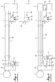
- FIGS. 1 and 2 show, by way of non-exclusive example, two versions of implementation of a control system of electric servomotors according to the invention.
- references 1 and 2 respectively denote a servomotor and the start of the power supply line of the servomotor, via a power cable 5 which comprises three phase wires forming a device phase.
- a major feature of the invention lies in the fact that this cable comprises a separate wire, called communication wire 7, which is integrated with the power cable 5 while being electrically isolated from the power son.
- the purpose of the communication wire 7 is to enable a control / control center 9 to communicate with the servomotor 1.
- the communication signals are applied between one of the supply phase wires 5, noted 5a. in the figures, and this communication wire 7. These signals have a frequency much higher than that of the alternating current and a smaller amplitude.
- a modem 11 is connected, on the one hand, by a terminal block 12 to the control / command center 9 and, on the other hand, 14 by two terminals between the communication wire 7 and the phase wire 5a to which the communication signals are superimposed.
- the current-DC supply of the modem is provided by a device 15 which produces the direct current from two phases 5 of the power supply of the servomotor.
- a modem 17 is associated with it via an intelligent interface 18. It is also connected at 19 between the communication wire 7 and the phase wire 5a and receives, at 21, the intelligent interface 18 of the booster, communication signals to be transmitted to the control and control center 9. The interface 18 also feeds into 23 the modem 17 in direct current.
- the electrical insulation with respect to the phases is provided at 16 in the modems 11 and 17 respectively control center / control side and servomotor side.
- the power supply 15 and the signals at the terminal block 12 are isolated from the phases 5.
- the power supply 23 and the communication signals at 21 are isolated from the phases.
- the figure 1 still shows at 24, in broken lines, the possibility of extending the communication wire to a control and control center 9 'provided with a modem 11' which is remote from the start of the power supply line in power 2, whereas, generally, the modems are arranged near the power start, if necessary in the power room itself.
- the figure 2 shows a system according to the invention, which allows to continue a communication between the servomotor and the control and control center 9, even in case of loss of power supply.
- the system comprises on the side of the control / control center 9 a separate direct-current supply device 25 which supplies the direct current via a DC / DC converter 27 to the modem 11.
- the power supply after being isolated, is connected between the phase wire 5a and the communication wire 7.
- the communication signal is superimposed on this power supply.
- the DC power supply and the communication signal are recovered at the servomotor by the modem 17, isolated and connected to the intelligent interface 18 at 21, and via a DC / DC converter 31.
- converter 31 converts the DC voltage into a DC power supply and feeds the interface 18 at 29 which then feeds the modem 17 at 23.
- the distance between the user-side transmitter modem and the servomotor that is to say the maximum length of the communication wire is at least 500 meters. In the case of a system according to figure 2 , the maximum length can be even greater.
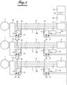
- the figure 3 shows the system according to the invention in a version adapted to control a plurality of different servomotors 1 by a single control / control center 9, via a data concentrator 33 which constitutes an interface between the control center and the modems 11 which each form the interface of a servomotor 1.
- the data namely the commands and signaling of the servomotors, are concentrated in the concentrator, that is to say at a single point.
- the interface modems 11 are connected to each other and to the concentrator via a field bus link 35.
- the concentrator 33 is connected to the control / control center 9 also via a field bus type link 37 which can be of a different type from that connecting the hub to the modems.
- an address is assigned to each interface modem 11, which allows the hub 33 to know the source of a signaling and to communicate an order to the destination servomotor.
- the link bus 35 may be redundant to increase the security of the system.
- the system according to the figure 3 has the advantage of reducing the number of cables between the control / command center 9 and the interface modems 11 which can be find with the power line start 2 in a local power.
- the signal superimposed on the supply voltage is of the FSK type, that is to say a frequency-modulated signal.
- Three frequencies are required to encode a message, namely a carrier frequency, a frequency which equals the value "0" and another frequency which corresponds to "1". These last two frequencies are defined according to the carrier and the rate that can be chosen for example between 600 bits / sec and 4800 bits / sec.
- the available carriers can be chosen, for example, between 60 kHz and 132.5 kHz.
- the frequencies of '1' and '0' could be, depending on the above-mentioned rates, for example, of the order of 60 kHz to 135 kHz. It is advantageous to provide electrical isolation between the phase wires connected to the mains and the communication wire with the other communication circuits. In this case, an insulation fault between phase and communication wire can not be transmitted on the control circuits.
- each servomotor With respect to a known network, to the carrier current, the distance between the modem and the servomotor is at least 500 meters. In addition, each servomotor currently has its own power line. With the system described, each servomotor remains with a single power cable including the communication wire, which has the advantage for the user of not having to change the power architecture of the servomotors. So, in the event of a fault, it does not affect the other servomotors. Since the signal is between a phase and an isolated wire of the network, because of this isolation, the invention with a communication wire allows higher amplitudes of the signal while avoiding pollute the electricity grid, and is less susceptible to pests, allowing to meet more stringent standards. Indeed, thanks to the invention, there is less pollution the electrical network. Therefore, maximum tolerated levels may be lower and therefore more stringent.
- the invention Compared with a known system of the fieldbus type, the invention has the advantage that instead of using a specific and therefore expensive cable, it only needs, for the communication wire, a single additional conductor in the power supply cable of the servomotor. On the other hand, the invention does not need redundancy because only one servomotor is connected to a communication wire link. Each servomotor has its own power cable and therefore its own communication wire connection.
Landscapes
- Engineering & Computer Science (AREA)
- Power Engineering (AREA)
- Computer Networks & Wireless Communication (AREA)
- Signal Processing (AREA)
- Control Of Multiple Motors (AREA)
- Cable Transmission Systems, Equalization Of Radio And Reduction Of Echo (AREA)
- Selective Calling Equipment (AREA)
Applications Claiming Priority (2)
| Application Number | Priority Date | Filing Date | Title |
|---|---|---|---|
| FR1455616A FR3022705B1 (fr) | 2014-06-18 | 2014-06-18 | Systeme de commande d'au moins un servomoteur a partir d'un centre de controle / commande |
| PCT/FR2015/051607 WO2015193615A1 (fr) | 2014-06-18 | 2015-06-17 | Système de commande d'au moins un servomoteur à partir d'un centre de contrôle/commande |
Publications (2)
| Publication Number | Publication Date |
|---|---|
| EP3158656A1 EP3158656A1 (fr) | 2017-04-26 |
| EP3158656B1 true EP3158656B1 (fr) | 2019-11-06 |
Family
ID=52016657
Family Applications (1)
| Application Number | Title | Priority Date | Filing Date |
|---|---|---|---|
| EP15738724.2A Active EP3158656B1 (fr) | 2014-06-18 | 2015-06-17 | Système de commande d'au moins un servomoteur à partir d'un centre de contrôle/commande |
Country Status (5)
| Country | Link |
|---|---|
| EP (1) | EP3158656B1 (da) |
| DK (1) | DK3158656T3 (da) |
| ES (1) | ES2768926T3 (da) |
| FR (1) | FR3022705B1 (da) |
| WO (1) | WO2015193615A1 (da) |
Family Cites Families (5)
| Publication number | Priority date | Publication date | Assignee | Title |
|---|---|---|---|---|
| GB1122801A (en) * | 1964-05-19 | 1968-08-07 | Serck Controls Ltd | Improvements in or relating to the transmission of pulse coded information |
| JP2007027041A (ja) * | 2005-07-21 | 2007-02-01 | Denso Corp | コネクタ付きケーブル |
| BRPI0721632A2 (pt) * | 2007-05-30 | 2013-02-13 | Cameron Int Corp | sistema de distribuiÇço de forÇa e sinal |
| US7902966B1 (en) * | 2007-06-18 | 2011-03-08 | Hewlett-Packard Development Company, L.P. | Microcontroller for controlling an actuator |
| JP5146378B2 (ja) * | 2009-03-19 | 2013-02-20 | 株式会社デンソーウェーブ | 産業機器のコントローラ |
-
2014
- 2014-06-18 FR FR1455616A patent/FR3022705B1/fr active Active
-
2015
- 2015-06-17 EP EP15738724.2A patent/EP3158656B1/fr active Active
- 2015-06-17 ES ES15738724T patent/ES2768926T3/es active Active
- 2015-06-17 WO PCT/FR2015/051607 patent/WO2015193615A1/fr not_active Ceased
- 2015-06-17 DK DK15738724.2T patent/DK3158656T3/da active
Non-Patent Citations (1)
| Title |
|---|
| None * |
Also Published As
| Publication number | Publication date |
|---|---|
| EP3158656A1 (fr) | 2017-04-26 |
| DK3158656T3 (da) | 2020-02-10 |
| FR3022705B1 (fr) | 2017-07-14 |
| FR3022705A1 (fr) | 2015-12-25 |
| WO2015193615A1 (fr) | 2015-12-23 |
| ES2768926T3 (es) | 2020-06-24 |
Similar Documents
| Publication | Publication Date | Title |
|---|---|---|
| EP2047609B1 (fr) | Système de reseau haute disponibilité | |
| EP3126854B1 (fr) | Procede de mesure de la consommation energetique des branches d'un reseau electrique et equipement de mesure mettant en oeuvre ledit procede | |
| CA2841347C (fr) | Mesure et modulation en temps reel de la consommation electrique d'une pluralite d'appareils electriques | |
| FR2797131A1 (fr) | Procede de distribution d'informations | |
| EP2347521B1 (fr) | Systeme avionique comprenant un controleur et au moins un peripherique relies par une ligne mutualisee pour la puissance et les donnees | |
| FR3083322A1 (fr) | Systeme et procede de localisation de defaut sur un reseau electrique poliphase utilisant l'evolution de tension directe et inverse | |
| FR2967832A1 (fr) | Depart equipe de moyens de protection et de mesure pour tableau basse tension | |
| WO1996036202A1 (fr) | Dispositif pour la commande et la surveillance a distance d'une lampe a decharge | |
| EP2009808B1 (fr) | Communication par courant porteur pour les tableaux centralisés de commande | |
| EP3158656B1 (fr) | Système de commande d'au moins un servomoteur à partir d'un centre de contrôle/commande | |
| FR2928478A1 (fr) | Module de communication destine a etre connecte a un equipement d'une installation industrielle | |
| EP3509180B1 (fr) | Procédé de réconfiguration d'un réseau d'alimentation électrique et réseau associé | |
| FR2628873A1 (fr) | Agencement de telecontrole par voie telephonique pour installation mono ou multifonction | |
| EP3150425A1 (fr) | Système amélioré d'alimentation d'une ligne aérienne de contact | |
| EP2738900B1 (fr) | Système d'alimentation en énergie électrique continue d'au moins deux charges à partir d'une source d'énergie électrique alternative et procédé de démarrage d'un tel système d'alimentation | |
| EP2795857B1 (fr) | Procédé de communication entre au moins un premier système et au moins un deuxième système au moyen d'une connexion serie full duplex synchrone | |
| EP2438687B1 (fr) | Adaptateur courant porteur intégré | |
| EP2820790B1 (fr) | Procede de communication periodique entre au moins un premier systeme et au moins un deuxieme systeme par l'intermediaire d'une liaison serie synchrone full duplex | |
| EP1100231B1 (fr) | Dispositif et boîtier pour raccordement à un réseau local. | |
| EP1550575B1 (fr) | Système et station d'alimentation d'une caténaire, et procédé d'interruption de cette alimentation | |
| EP2957451B1 (fr) | Système de contrôle de l'alimentation d'un secteur électrique de caténaire d'une infrastructure ferroviaire | |
| FR2680617A1 (fr) | Dispositif de raccordement d'un reseau de transmission de donnees a une pluralite d'abonnes. | |
| EP1776594A1 (fr) | Appareil de mesure detaillee de consommation electrique | |
| WO2004064256A1 (fr) | Installation permettant l'echange d'informations entre un emetteur et un recepteur | |
| BE682309A (da) |
Legal Events
| Date | Code | Title | Description |
|---|---|---|---|
| STAA | Information on the status of an ep patent application or granted ep patent |
Free format text: STATUS: THE INTERNATIONAL PUBLICATION HAS BEEN MADE |
|
| PUAI | Public reference made under article 153(3) epc to a published international application that has entered the european phase |
Free format text: ORIGINAL CODE: 0009012 |
|
| STAA | Information on the status of an ep patent application or granted ep patent |
Free format text: STATUS: REQUEST FOR EXAMINATION WAS MADE |
|
| 17P | Request for examination filed |
Effective date: 20170112 |
|
| AK | Designated contracting states |
Kind code of ref document: A1 Designated state(s): AL AT BE BG CH CY CZ DE DK EE ES FI FR GB GR HR HU IE IS IT LI LT LU LV MC MK MT NL NO PL PT RO RS SE SI SK SM TR |
|
| AX | Request for extension of the european patent |
Extension state: BA ME |
|
| DAV | Request for validation of the european patent (deleted) | ||
| DAX | Request for extension of the european patent (deleted) | ||
| STAA | Information on the status of an ep patent application or granted ep patent |
Free format text: STATUS: EXAMINATION IS IN PROGRESS |
|
| 17Q | First examination report despatched |
Effective date: 20180220 |
|
| RIC1 | Information provided on ipc code assigned before grant |
Ipc: H04B 3/56 20060101AFI20190328BHEP Ipc: H04B 3/54 20060101ALI20190328BHEP |
|
| GRAP | Despatch of communication of intention to grant a patent |
Free format text: ORIGINAL CODE: EPIDOSNIGR1 |
|
| STAA | Information on the status of an ep patent application or granted ep patent |
Free format text: STATUS: GRANT OF PATENT IS INTENDED |
|
| INTG | Intention to grant announced |
Effective date: 20190516 |
|
| GRAS | Grant fee paid |
Free format text: ORIGINAL CODE: EPIDOSNIGR3 |
|
| GRAA | (expected) grant |
Free format text: ORIGINAL CODE: 0009210 |
|
| STAA | Information on the status of an ep patent application or granted ep patent |
Free format text: STATUS: THE PATENT HAS BEEN GRANTED |
|
| AK | Designated contracting states |
Kind code of ref document: B1 Designated state(s): AL AT BE BG CH CY CZ DE DK EE ES FI FR GB GR HR HU IE IS IT LI LT LU LV MC MK MT NL NO PL PT RO RS SE SI SK SM TR |
|
| REG | Reference to a national code |
Ref country code: GB Ref legal event code: FG4D Free format text: NOT ENGLISH |
|
| REG | Reference to a national code |
Ref country code: CH Ref legal event code: EP Ref country code: AT Ref legal event code: REF Ref document number: 1200201 Country of ref document: AT Kind code of ref document: T Effective date: 20191115 |
|
| REG | Reference to a national code |
Ref country code: IE Ref legal event code: FG4D Free format text: LANGUAGE OF EP DOCUMENT: FRENCH |
|
| REG | Reference to a national code |
Ref country code: DE Ref legal event code: R096 Ref document number: 602015041136 Country of ref document: DE |
|
| REG | Reference to a national code |
Ref country code: DK Ref legal event code: T3 Effective date: 20200207 |
|
| REG | Reference to a national code |
Ref country code: NO Ref legal event code: T2 Effective date: 20191106 |
|
| REG | Reference to a national code |
Ref country code: LT Ref legal event code: MG4D |
|
| PG25 | Lapsed in a contracting state [announced via postgrant information from national office to epo] |
Ref country code: BG Free format text: LAPSE BECAUSE OF FAILURE TO SUBMIT A TRANSLATION OF THE DESCRIPTION OR TO PAY THE FEE WITHIN THE PRESCRIBED TIME-LIMIT Effective date: 20200206 Ref country code: GR Free format text: LAPSE BECAUSE OF FAILURE TO SUBMIT A TRANSLATION OF THE DESCRIPTION OR TO PAY THE FEE WITHIN THE PRESCRIBED TIME-LIMIT Effective date: 20200207 Ref country code: LT Free format text: LAPSE BECAUSE OF FAILURE TO SUBMIT A TRANSLATION OF THE DESCRIPTION OR TO PAY THE FEE WITHIN THE PRESCRIBED TIME-LIMIT Effective date: 20191106 Ref country code: FI Free format text: LAPSE BECAUSE OF FAILURE TO SUBMIT A TRANSLATION OF THE DESCRIPTION OR TO PAY THE FEE WITHIN THE PRESCRIBED TIME-LIMIT Effective date: 20191106 Ref country code: SE Free format text: LAPSE BECAUSE OF FAILURE TO SUBMIT A TRANSLATION OF THE DESCRIPTION OR TO PAY THE FEE WITHIN THE PRESCRIBED TIME-LIMIT Effective date: 20191106 Ref country code: PL Free format text: LAPSE BECAUSE OF FAILURE TO SUBMIT A TRANSLATION OF THE DESCRIPTION OR TO PAY THE FEE WITHIN THE PRESCRIBED TIME-LIMIT Effective date: 20191106 Ref country code: LV Free format text: LAPSE BECAUSE OF FAILURE TO SUBMIT A TRANSLATION OF THE DESCRIPTION OR TO PAY THE FEE WITHIN THE PRESCRIBED TIME-LIMIT Effective date: 20191106 Ref country code: PT Free format text: LAPSE BECAUSE OF FAILURE TO SUBMIT A TRANSLATION OF THE DESCRIPTION OR TO PAY THE FEE WITHIN THE PRESCRIBED TIME-LIMIT Effective date: 20200306 |
|
| REG | Reference to a national code |
Ref country code: NL Ref legal event code: FP |
|
| PG25 | Lapsed in a contracting state [announced via postgrant information from national office to epo] |
Ref country code: HR Free format text: LAPSE BECAUSE OF FAILURE TO SUBMIT A TRANSLATION OF THE DESCRIPTION OR TO PAY THE FEE WITHIN THE PRESCRIBED TIME-LIMIT Effective date: 20191106 Ref country code: RS Free format text: LAPSE BECAUSE OF FAILURE TO SUBMIT A TRANSLATION OF THE DESCRIPTION OR TO PAY THE FEE WITHIN THE PRESCRIBED TIME-LIMIT Effective date: 20191106 Ref country code: IS Free format text: LAPSE BECAUSE OF FAILURE TO SUBMIT A TRANSLATION OF THE DESCRIPTION OR TO PAY THE FEE WITHIN THE PRESCRIBED TIME-LIMIT Effective date: 20200306 |
|
| REG | Reference to a national code |
Ref country code: ES Ref legal event code: FG2A Ref document number: 2768926 Country of ref document: ES Kind code of ref document: T3 Effective date: 20200624 |
|
| PG25 | Lapsed in a contracting state [announced via postgrant information from national office to epo] |
Ref country code: AL Free format text: LAPSE BECAUSE OF FAILURE TO SUBMIT A TRANSLATION OF THE DESCRIPTION OR TO PAY THE FEE WITHIN THE PRESCRIBED TIME-LIMIT Effective date: 20191106 |
|
| PG25 | Lapsed in a contracting state [announced via postgrant information from national office to epo] |
Ref country code: RO Free format text: LAPSE BECAUSE OF FAILURE TO SUBMIT A TRANSLATION OF THE DESCRIPTION OR TO PAY THE FEE WITHIN THE PRESCRIBED TIME-LIMIT Effective date: 20191106 Ref country code: CZ Free format text: LAPSE BECAUSE OF FAILURE TO SUBMIT A TRANSLATION OF THE DESCRIPTION OR TO PAY THE FEE WITHIN THE PRESCRIBED TIME-LIMIT Effective date: 20191106 Ref country code: EE Free format text: LAPSE BECAUSE OF FAILURE TO SUBMIT A TRANSLATION OF THE DESCRIPTION OR TO PAY THE FEE WITHIN THE PRESCRIBED TIME-LIMIT Effective date: 20191106 |
|
| REG | Reference to a national code |
Ref country code: DE Ref legal event code: R097 Ref document number: 602015041136 Country of ref document: DE |
|
| REG | Reference to a national code |
Ref country code: AT Ref legal event code: MK05 Ref document number: 1200201 Country of ref document: AT Kind code of ref document: T Effective date: 20191106 |
|
| PG25 | Lapsed in a contracting state [announced via postgrant information from national office to epo] |
Ref country code: SK Free format text: LAPSE BECAUSE OF FAILURE TO SUBMIT A TRANSLATION OF THE DESCRIPTION OR TO PAY THE FEE WITHIN THE PRESCRIBED TIME-LIMIT Effective date: 20191106 Ref country code: SM Free format text: LAPSE BECAUSE OF FAILURE TO SUBMIT A TRANSLATION OF THE DESCRIPTION OR TO PAY THE FEE WITHIN THE PRESCRIBED TIME-LIMIT Effective date: 20191106 |
|
| PLBE | No opposition filed within time limit |
Free format text: ORIGINAL CODE: 0009261 |
|
| STAA | Information on the status of an ep patent application or granted ep patent |
Free format text: STATUS: NO OPPOSITION FILED WITHIN TIME LIMIT |
|
| 26N | No opposition filed |
Effective date: 20200807 |
|
| PG25 | Lapsed in a contracting state [announced via postgrant information from national office to epo] |
Ref country code: SI Free format text: LAPSE BECAUSE OF FAILURE TO SUBMIT A TRANSLATION OF THE DESCRIPTION OR TO PAY THE FEE WITHIN THE PRESCRIBED TIME-LIMIT Effective date: 20191106 Ref country code: AT Free format text: LAPSE BECAUSE OF FAILURE TO SUBMIT A TRANSLATION OF THE DESCRIPTION OR TO PAY THE FEE WITHIN THE PRESCRIBED TIME-LIMIT Effective date: 20191106 |
|
| PG25 | Lapsed in a contracting state [announced via postgrant information from national office to epo] |
Ref country code: MC Free format text: LAPSE BECAUSE OF FAILURE TO SUBMIT A TRANSLATION OF THE DESCRIPTION OR TO PAY THE FEE WITHIN THE PRESCRIBED TIME-LIMIT Effective date: 20191106 |
|
| REG | Reference to a national code |
Ref country code: CH Ref legal event code: PL |
|
| PG25 | Lapsed in a contracting state [announced via postgrant information from national office to epo] |
Ref country code: LU Free format text: LAPSE BECAUSE OF NON-PAYMENT OF DUE FEES Effective date: 20200617 |
|
| PG25 | Lapsed in a contracting state [announced via postgrant information from national office to epo] |
Ref country code: CH Free format text: LAPSE BECAUSE OF NON-PAYMENT OF DUE FEES Effective date: 20200630 Ref country code: IE Free format text: LAPSE BECAUSE OF NON-PAYMENT OF DUE FEES Effective date: 20200617 Ref country code: LI Free format text: LAPSE BECAUSE OF NON-PAYMENT OF DUE FEES Effective date: 20200630 |
|
| PG25 | Lapsed in a contracting state [announced via postgrant information from national office to epo] |
Ref country code: TR Free format text: LAPSE BECAUSE OF FAILURE TO SUBMIT A TRANSLATION OF THE DESCRIPTION OR TO PAY THE FEE WITHIN THE PRESCRIBED TIME-LIMIT Effective date: 20191106 Ref country code: MT Free format text: LAPSE BECAUSE OF FAILURE TO SUBMIT A TRANSLATION OF THE DESCRIPTION OR TO PAY THE FEE WITHIN THE PRESCRIBED TIME-LIMIT Effective date: 20191106 Ref country code: CY Free format text: LAPSE BECAUSE OF FAILURE TO SUBMIT A TRANSLATION OF THE DESCRIPTION OR TO PAY THE FEE WITHIN THE PRESCRIBED TIME-LIMIT Effective date: 20191106 |
|
| PG25 | Lapsed in a contracting state [announced via postgrant information from national office to epo] |
Ref country code: MK Free format text: LAPSE BECAUSE OF FAILURE TO SUBMIT A TRANSLATION OF THE DESCRIPTION OR TO PAY THE FEE WITHIN THE PRESCRIBED TIME-LIMIT Effective date: 20191106 |
|
| PGFP | Annual fee paid to national office [announced via postgrant information from national office to epo] |
Ref country code: GB Payment date: 20250621 Year of fee payment: 11 Ref country code: DK Payment date: 20250620 Year of fee payment: 11 |
|
| PGFP | Annual fee paid to national office [announced via postgrant information from national office to epo] |
Ref country code: NO Payment date: 20250626 Year of fee payment: 11 |
|
| PGFP | Annual fee paid to national office [announced via postgrant information from national office to epo] |
Ref country code: NL Payment date: 20250621 Year of fee payment: 11 Ref country code: BE Payment date: 20250621 Year of fee payment: 11 |
|
| PGFP | Annual fee paid to national office [announced via postgrant information from national office to epo] |
Ref country code: FR Payment date: 20250602 Year of fee payment: 11 |
|
| PGFP | Annual fee paid to national office [announced via postgrant information from national office to epo] |
Ref country code: ES Payment date: 20250701 Year of fee payment: 11 |
|
| PGFP | Annual fee paid to national office [announced via postgrant information from national office to epo] |
Ref country code: DE Payment date: 20250630 Year of fee payment: 11 |
|
| PGFP | Annual fee paid to national office [announced via postgrant information from national office to epo] |
Ref country code: IT Payment date: 20250627 Year of fee payment: 11 |