EP3159105A2 - Schleifmaschine mit beweglicher wasserwanne - Google Patents
Schleifmaschine mit beweglicher wasserwanne Download PDFInfo
- Publication number
- EP3159105A2 EP3159105A2 EP16193290.0A EP16193290A EP3159105A2 EP 3159105 A2 EP3159105 A2 EP 3159105A2 EP 16193290 A EP16193290 A EP 16193290A EP 3159105 A2 EP3159105 A2 EP 3159105A2
- Authority
- EP
- European Patent Office
- Prior art keywords
- grinding machine
- trough
- shaft
- holder
- locking
- Prior art date
- Legal status (The legal status is an assumption and is not a legal conclusion. Google has not performed a legal analysis and makes no representation as to the accuracy of the status listed.)
- Granted
Links
Images
Classifications
-
- B—PERFORMING OPERATIONS; TRANSPORTING
- B24—GRINDING; POLISHING
- B24B—MACHINES, DEVICES, OR PROCESSES FOR GRINDING OR POLISHING; DRESSING OR CONDITIONING OF ABRADING SURFACES; FEEDING OF GRINDING, POLISHING, OR LAPPING AGENTS
- B24B3/00—Sharpening cutting edges, e.g. of tools; Accessories therefor, e.g. for holding the tools
- B24B3/36—Sharpening cutting edges, e.g. of tools; Accessories therefor, e.g. for holding the tools of cutting blades
-
- B—PERFORMING OPERATIONS; TRANSPORTING
- B23—MACHINE TOOLS; METAL-WORKING NOT OTHERWISE PROVIDED FOR
- B23Q—DETAILS, COMPONENTS, OR ACCESSORIES FOR MACHINE TOOLS, e.g. ARRANGEMENTS FOR COPYING OR CONTROLLING; MACHINE TOOLS IN GENERAL CHARACTERISED BY THE CONSTRUCTION OF PARTICULAR DETAILS OR COMPONENTS; COMBINATIONS OR ASSOCIATIONS OF METAL-WORKING MACHINES, NOT DIRECTED TO A PARTICULAR RESULT
- B23Q11/00—Accessories fitted to machine tools for keeping tools or parts of the machine in good working condition or for cooling work; Safety devices specially combined with or arranged in, or specially adapted for use in connection with, machine tools
- B23Q11/0042—Devices for removing chips
- B23Q11/0067—Devices for removing chips chip containers located under a machine or under a chip conveyor
-
- B—PERFORMING OPERATIONS; TRANSPORTING
- B23—MACHINE TOOLS; METAL-WORKING NOT OTHERWISE PROVIDED FOR
- B23Q—DETAILS, COMPONENTS, OR ACCESSORIES FOR MACHINE TOOLS, e.g. ARRANGEMENTS FOR COPYING OR CONTROLLING; MACHINE TOOLS IN GENERAL CHARACTERISED BY THE CONSTRUCTION OF PARTICULAR DETAILS OR COMPONENTS; COMBINATIONS OR ASSOCIATIONS OF METAL-WORKING MACHINES, NOT DIRECTED TO A PARTICULAR RESULT
- B23Q11/00—Accessories fitted to machine tools for keeping tools or parts of the machine in good working condition or for cooling work; Safety devices specially combined with or arranged in, or specially adapted for use in connection with, machine tools
- B23Q11/10—Arrangements for cooling or lubricating tools or work
- B23Q11/1007—Arrangements for cooling or lubricating tools or work by submerging the tools or work partially or entirely in a liquid
-
- B—PERFORMING OPERATIONS; TRANSPORTING
- B24—GRINDING; POLISHING
- B24B—MACHINES, DEVICES, OR PROCESSES FOR GRINDING OR POLISHING; DRESSING OR CONDITIONING OF ABRADING SURFACES; FEEDING OF GRINDING, POLISHING, OR LAPPING AGENTS
- B24B27/00—Other grinding machines or devices
- B24B27/02—Bench grinders
-
- B—PERFORMING OPERATIONS; TRANSPORTING
- B24—GRINDING; POLISHING
- B24B—MACHINES, DEVICES, OR PROCESSES FOR GRINDING OR POLISHING; DRESSING OR CONDITIONING OF ABRADING SURFACES; FEEDING OF GRINDING, POLISHING, OR LAPPING AGENTS
- B24B53/00—Devices or means for dressing or conditioning abrasive surfaces
- B24B53/007—Cleaning of grinding wheels
-
- B—PERFORMING OPERATIONS; TRANSPORTING
- B24—GRINDING; POLISHING
- B24B—MACHINES, DEVICES, OR PROCESSES FOR GRINDING OR POLISHING; DRESSING OR CONDITIONING OF ABRADING SURFACES; FEEDING OF GRINDING, POLISHING, OR LAPPING AGENTS
- B24B55/00—Safety devices for grinding or polishing machines; Accessories fitted to grinding or polishing machines for keeping tools or parts of the machine in good working condition
- B24B55/02—Equipment for cooling the grinding surfaces, e.g. devices for feeding coolant
-
- B—PERFORMING OPERATIONS; TRANSPORTING
- B24—GRINDING; POLISHING
- B24B—MACHINES, DEVICES, OR PROCESSES FOR GRINDING OR POLISHING; DRESSING OR CONDITIONING OF ABRADING SURFACES; FEEDING OF GRINDING, POLISHING, OR LAPPING AGENTS
- B24B57/00—Devices for feeding, applying, grading or recovering grinding, polishing or lapping agents
- B24B57/02—Devices for feeding, applying, grading or recovering grinding, polishing or lapping agents for feeding of fluid, sprayed, pulverised, or liquefied grinding, polishing or lapping agents
Definitions
- the present invention relates to a grinding machine comprising a movable holder for a trough for grinding liquid.
- edged tools such as handheld knives or wood working tools such as plane irons, wood chisels or spoke shave blades
- a bench type grinding machine comprising a motor driven grindstone.
- the edged tool is held with a correct angle in contact with the grindstone and is moved across the grindstone by an operator until sufficiently sharpened.
- the grindstone is wetted with grinding liquid.
- the grinding machine comprises a trough for the grinding liquid, typically water, arranged underneath the grindstone.
- EP2883655A1 shows a grinding machine of the bench type having a trough for grinding liquid.
- a grinding machine 100 comprising a housing 1 having a base 2 for supporting the grinding machine, a shaft 3 for holding a grindstone 4, a motor for rotating the shaft 3 and a trough holder 10 for holding a trough 6 for grinding liquid, the through holder 10 being arranged below the shaft 3, characterized in that the trough holder 10 is movable in vertical direction between the base 2 of the housing 1 and the shaft 3 for holding a grindstone and that the grinding machine comprises a lifting/lowering arrangement 20 for moving the trough holder 10 in said vertical direction
- the trough holder may be lowered to a mounting position where it is easy for the user of the machine to push a trough for grinding liquid on to the trough holder.
- the trough holder may thereafter, together with the through for grinding liquid, be raised by the lifting/lowering arrangement to a position for wetting a grindstone.
- the trough holder may be lowered again such that the grindstone is free of contact with the grinding liquid.
- a further advantage of the grinding machine according to the present disclosure is that it allows for simple use of grindstones with different diameters. It is easy to raise the trough holder to different heights in dependency of the diameter of the grindstone such that grindstones of both large and small diameter may be wetted. The same trough may thereby be used for grindstones of both large and small diameter.
- the lifting/lowering arrangement 20 comprises an actuator 21 having a first coupling means 24 and a second coupling means 25 arranged on the trough holder 10, wherein the coupling means 24, 25 are configured to couple the actuator 21 and the trough holder 10 such that actuation of the actuator 21 causes the trough holder 10 to move in vertical direction.
- first coupling means 24 and the second coupling means 25 comprises intermeshing gears.
- Intermeshing gears provides robust and controlled coupling, free of play, between the actuator and the trough holder.
- the first coupling means 24 is a gear wheel and the second coupling means 25 is a toothed rack 25.
- This type of coupling is easy to maneuver by the operator since turning of the actuator and thereby the rotation of gear wheel results in a corresponding linear displacement of the toothed rack and the trough holder.
- the gear wheel and the toothed rack it is further possible to control the gearing ratio, i.e. the resulting vertical displacement of the trough holder in dependency of the degree of turning of the gear wheel.
- the trough holder 10 is configured to be guided in a vertical slot 5 in the housing 1 of the grinding machine, wherein the vertical slot 5 extends along an axis (X) extending from the base 2 of the grinding machine through the shaft 3 for holding a grindstone.
- X axis
- the trough holder 10 comprises at least one support arm 14 for supporting a trough 6 for grinding liquid extending from an external side surface 11 of the trough holder 10.
- the external side surface 11 of the trough holder 10 comprises a yoke 15, whereby a first support arm 14 extends from a first end of the yoke 15 and a second support arm 14 extends from a second end of the yoke 15.
- the yoke makes it possible to supporting a trough for grinding liquid in a simple and stable manner.
- the second coupling means 25 is arranged on an internal side surface 12 of the trough holder 10.
- the actuator 21 is an actuator shaft 21 having a first end 22 and a second end 23, wherein the first end 22 and the second end 23 are journalled in the housing 1 of the grinding machine, whereby the first end 22 of the actuator shaft 21 is arranged to be manually turned by an operator of the grinding machine and whereby the second end 23 of the actuator shaft 21 comprises said first coupling means 24.
- the grinding machine comprises a locking arrangement 40 for locking the actuator shaft 21 from rotating, wherein the locking arrangement comprises:
- the locking arrangement 40 effective secures the trough for grinding liquid in a selected position.
- vertical direction is meant a direction which is perpendicular to the base 2 of the grinding machine.
- the grinding machine according to the present disclosure will now be described more fully hereinafter.
- the grinding machine according to the present disclosure may however be embodied in many different forms and should not be construed as limited to the embodiment set forth herein. Rather, this embodiment is provided by way of example so that this disclosure will be thorough and complete, and will fully convey the scope of the present disclosure to those persons skilled in the art.
- Like reference numbers refer to like elements throughout the description.
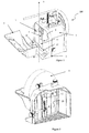
- FIG 1 shows schematically a grinding machine 100 according to a first preferred embodiment of the invention in perspective front view.
- the grinding machine 100 is of the bench type, i.e. it is of a design that allows it to be placed on a table in a workshop and to be operated manually by a person.
- the grinding machine 100 comprises a housing 1.
- the housing has a plane base 2 on which the grinding machine is supported.
- the grinding machine comprises a shaft 3 which is rotated by an electrical motor (not shown) enclosed in the housing 1.
- the shaft 3 is provided to hold and rotate a grindstone against which blades are ground or sharpened.
- the grindstone is not shown in figure 1 for clarity reasons.
- figures 2 , 5 and 6 shows alternative views of the grinding machine of figure 1 with a grindstone 4 mounted on the shaft 3.
- the grinding machine 100 comprises a trough holder 10 for holding a trough 6 for grinding liquid.
- the trough 6 has been removed from the grinding machine in order to make the parts of the trough holder 10 visible.
- the trough holder 10 comprises two support arms 14 which extend from an external side surface 11 of the trough holder 10, i.e. the side of the trough holder section that faces away from the housing 1.
- the external side surface 11 of the trough holder 10 comprises a yoke 15, whereby the two support arms 14 extend from a respective end of the yoke 15.
- the trough 6 for grinding liquid is carried by, i.e. supported on the support arms 14.
- the trough holder 10 is arranged below, i.e. underneath the shaft 3.
- the trough holder 10 is movable in vertical direction along the housing 1 of the grinding machine.
- the trough holder is thereby movable in at least a portion of the area between the base 2 and the shaft 3 for holding a grindstone.
- this achieved by guiding the trough holder 10 in a slot 5, e.g. a groove, which extends in vertical direction from the base 2 of the housing towards the shaft 3 for supporting the grindstone.
- the straight slot 5 is centered with respect to the shaft 3 for supporting the grindstone.
- the trough holder 10 is thus movable in vertical direction along an axis (X) which extends from the base 2 of the housing through the shaft 3 for supporting the grindstone.
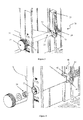
- Figure 2 is a cross-sectional view of the grinding machine 100 shown the interior of the housing 1 in the area behind the grindstone 4.
- Figure 2 shows an internal side surface 12 of the trough holder 10.
- the internal side surface 12 of trough holder 10 is connected to the external side surface 11 of the trough holder 10 (shown in figure 1 ) through the slot 5 by an intermediate piece (not shown).
- the trough holder 10 may slide along the slot 5 but is prevented from moving in any other direction.
- the grinding machine comprises a lifting/lowering arrangement 20 for moving the trough holder 10 along the housing 1 of the grinding machine.
- Figure 2 shows a lifting/lowering arrangement 20 for moving the trough holder.
- the lifting/lowering arrangement is shown in detail in figure 3 .
- FIG 3 shows a detailed view of the lifting/lowering arrangement 20 shown in figure 2 .
- the lifting/lowering arrangement 20 comprises an actuator 21 in the form an actuator shaft 21 which has a first end 22 and a second end 23.
- the first end 22 and the second end 23 of the actuator 21 are journalled in a respective first and second attachment 31, 32 in the housing 1 of the grinding machine.
- the attachments 31, 32 may be bearings 31, 32, i.e. comprising circular openings for receiving the actuator 21.
- the actuator 21 may be manually turned in clockwise/anticlockwise direction by an operator.
- the first end 22 of the actuator 21 extends to the outside of the housing 1 and may be provided with a knob 27.
- the second end 23 of the actuator 21 comprises a first coupling means 24 in the form of a gear wheel.
- the lifting/lowering arrangement 20 further comprises a second coupling means 25 in the form of a toothed rack.
- the second coupling means 25 is arranged on the internal side surface 12 of the trough holder 10.
- the second coupling means 25 is thereby fixed to the internal side surface 12 of the trough holder 10 and oriented such that it extends in vertical direction of the internal side surface 12 of the trough holder 10, i.e. parallel with the slot 5.
- the first coupling means 24 on the actuator 21 and the second coupling means 25 on the internal side surface 12 of the trough holder 10 are configured such that they engage each other.
- the teeth of the gear wheel on the actuator shaft 21 are configured such that they engage the teeth of the toothed rack on the internal side surface 12 of the guiding section 11.
- the teeth on the gear wheel on the end of the actuator shaft 21 engages the teeth on the toothed rack and forces the trough holder 10 to move along the slot 5 in the housing 1.
- Clockwise turning of the actuator shaft 21 causes the trough holder 10 to move upwards, i.e. in direction towards the shaft 3 for holding a grindstone.
- Anti-clockwise turning of the actuator shaft 21 causes the trough holder 10 to move downwards, i.e. in direction towards the base 2 of the grinding machine.
- the lifting lowering arrangement 20 may further comprise a locking arrangement 40 for locking the trough holder 10, and thus the trough 6 for grinding liquid, in position after turning of the actuator shaft.
- Figure 4 shows a closed-up view of a lifting/lowering arrangement 20 as described in figure 3 including a locking arrangement 40.
- the locking arrangement 40 comprises a locking sleeve 41 which is arranged around the second end 23 of the actuator shaft 21.
- the locking sleeve 41 is of quadratic cross-section, having four sides of which one side is attached to the housing 1 of the grinding machine.
- An end surface of the locking sleeve 41 is directed towards the coupling means 24 of the actuator shaft 21 and comprises locking notches 42.
- one locking notch 42 is provided on each side of the locking sleeve 41.
- the locking sleeve is cylindrical.
- the locking arrangement 40 further comprises locking teeth 43 which are arranged around the circumference of the second end 23 of the actuator shaft 21 and faces the end of the locking sleeve 41.
- the locking teeth 43 are dimensioned such that their size and shape correspond to the size and shape of the locking notches 42 in the locking sleeve 41.
- the actuator shaft 21 is arranged slidable in axial direction such that the locking teeth 43 may be moved into and out of engagement with the locking notches 42 in the locking sleeve 41.
- the actuator shaft 21 is spring biased such that the locking teeth 43 on the actuator shaft 21 are forced by spring force in axial direction towards the locking sleeve 41.
- the locking arrangement 40 may thereby comprise a spring 28, e.g. a helical pressure spring, which is arranged around the first end 22 of the actuator shaft 21 such that the opposite ends of the spring 28 are in contact with the housing 1 and the knob 27 respectively.
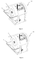
- Figure 5 shows the grinding machine 100 in a grinding position in which the trough 6 for grinding liquid is raised such that the grindstone 4 is contacting the grinding liquid (not shown) in the trough.
- Figure 6 shows the grinding machine 100 in a mounting position in which the trough 6 for grinding liquid is lowered towards the base 2 such that the grindstone 4 is free of contact with the grinding liquid in the trough. In this position the trough 6 may be removed from the trough holder 10.
- the lifting/lowering arrangement may be realized with first and second coupling means in the form of friction surfaces instead of intermeshing teeth. It is also possible to include further coupling means, such as linkages, in the lifting/lowering arrangement.
Landscapes
- Engineering & Computer Science (AREA)
- Mechanical Engineering (AREA)
- Constituent Portions Of Griding Lathes, Driving, Sensing And Control (AREA)
- Grinding Of Cylindrical And Plane Surfaces (AREA)
Applications Claiming Priority (1)
| Application Number | Priority Date | Filing Date | Title |
|---|---|---|---|
| SE1551356A SE538962C2 (en) | 2015-10-21 | 2015-10-21 | Grinding machine with movable water trough |
Publications (3)
| Publication Number | Publication Date |
|---|---|
| EP3159105A2 true EP3159105A2 (de) | 2017-04-26 |
| EP3159105A3 EP3159105A3 (de) | 2017-06-14 |
| EP3159105B1 EP3159105B1 (de) | 2020-11-04 |
Family
ID=57123914
Family Applications (1)
| Application Number | Title | Priority Date | Filing Date |
|---|---|---|---|
| EP16193290.0A Active EP3159105B1 (de) | 2015-10-21 | 2016-10-11 | Schleifmaschine mit beweglicher wasserwanne |
Country Status (3)
| Country | Link |
|---|---|
| US (1) | US10272534B2 (de) |
| EP (1) | EP3159105B1 (de) |
| SE (1) | SE538962C2 (de) |
Families Citing this family (3)
| Publication number | Priority date | Publication date | Assignee | Title |
|---|---|---|---|---|
| CN112518436B (zh) * | 2020-11-20 | 2021-10-08 | 杭州电子科技大学 | 一种基于电磁原理的木质抛光工具磨抛工艺 |
| USD1007269S1 (en) * | 2021-01-08 | 2023-12-12 | Tormek Ab | Kitchen knife sharpener |
| USD1095201S1 (en) * | 2024-04-17 | 2025-09-30 | Shaojuan LIN | Sharpening stone |
Citations (1)
| Publication number | Priority date | Publication date | Assignee | Title |
|---|---|---|---|---|
| EP2883655A1 (de) | 2013-12-12 | 2015-06-17 | Tormek AB | Einspannmittel für eine Schleifmaschine und Schleifmaschine mit den Einspannmitteln |
Family Cites Families (15)
| Publication number | Priority date | Publication date | Assignee | Title |
|---|---|---|---|---|
| US570110A (en) * | 1896-10-27 | John w | ||
| US49928A (en) * | 1865-09-12 | Improvement in grindstones | ||
| US144891A (en) * | 1873-11-25 | Improvement in devices for wetting grindstones | ||
| US538331A (en) * | 1895-04-30 | Mechanism for wetting emery-wheels | ||
| US665380A (en) * | 1900-10-13 | 1901-01-01 | B F Barnes Company | Grinding-wheel support. |
| US844497A (en) * | 1906-09-21 | 1907-02-19 | Emery H Cheesbro | Water pan or hood for grindstones. |
| US1569757A (en) * | 1923-03-03 | 1926-01-12 | Joseph H King | Grindstone |
| US2331876A (en) * | 1941-12-01 | 1943-10-19 | Bendix Aviat Corp | Safety system |
| DE1084109B (de) * | 1957-08-13 | 1960-06-23 | Heinz Roeber | Kuehleinrichtung fuer das Werkstueck an Werkzeugmaschinen, insbesondere an Zahnradstossmaschinen |
| FR2453711A1 (fr) * | 1979-04-14 | 1980-11-07 | Hanning Elektro Werke | Machine servant a aiguiser des outils et des instruments tranchants ou d'autres objets a meuler |
| US6381862B1 (en) * | 1999-12-10 | 2002-05-07 | David Burke Doman | Hollow grinder bevel angle control mechanism |
| DE202005001316U1 (de) * | 2005-01-26 | 2005-03-31 | Mann & Hummel Gmbh | Sammeltrog für eine Werkzeugmaschine |
| US20070218814A1 (en) * | 2006-02-21 | 2007-09-20 | Schwaiger Barry M | Variable Speed Wet Sharpener And Methods Relating To Same |
| US7121923B1 (en) * | 2006-04-20 | 2006-10-17 | Martin P. Gottlieb | Dual position sharpening device |
| SE537247C2 (sv) * | 2012-05-03 | 2015-03-17 | Tormek Ab | Knivjiggaggregat |
-
2015
- 2015-10-21 SE SE1551356A patent/SE538962C2/en unknown
-
2016
- 2016-10-11 EP EP16193290.0A patent/EP3159105B1/de active Active
- 2016-10-19 US US15/298,009 patent/US10272534B2/en active Active
Patent Citations (1)
| Publication number | Priority date | Publication date | Assignee | Title |
|---|---|---|---|---|
| EP2883655A1 (de) | 2013-12-12 | 2015-06-17 | Tormek AB | Einspannmittel für eine Schleifmaschine und Schleifmaschine mit den Einspannmitteln |
Also Published As
| Publication number | Publication date |
|---|---|
| EP3159105B1 (de) | 2020-11-04 |
| SE1551356A1 (en) | 2017-03-07 |
| SE538962C2 (en) | 2017-03-07 |
| EP3159105A3 (de) | 2017-06-14 |
| US20170113317A1 (en) | 2017-04-27 |
| US10272534B2 (en) | 2019-04-30 |
Similar Documents
| Publication | Publication Date | Title |
|---|---|---|
| DE102016115276B4 (de) | Kraftwerkzeug mit innerem gehäuse | |
| US10272534B2 (en) | Grinding machine with movable water trough | |
| EP3380271A1 (de) | Tragbare, handgeführte trennschleifmaschine | |
| WO2007113510A1 (en) | Tool holding jig | |
| EP3173187A1 (de) | Tragbare, handgeführte trennschleifmaschine | |
| EP0471490A2 (de) | Mehrzweck-Werkzeug-Schleifmaschine | |
| EP3718690A1 (de) | Anordnung zum schleifen von kantigen werkzeugen | |
| EP1795301B1 (de) | Schleifteller mit Schnellspanneinrichtung sowie Tellerschleifer mit einem solchen Schleifteller& x9; | |
| JP5950377B2 (ja) | ソーチェーンの刃の目立て器 | |
| EP1980364B1 (de) | Verbesserte Messerschärfvorrichtung | |
| KR20120096976A (ko) | 형강재 절단 원형 톱날의 연마용 자동 승강장치 | |
| DE700529C (de) | Maschine zum Schleifen der Zapfen gekroepfter Wellen | |
| CN211101969U (zh) | 一种滚齿机用固定工装 | |
| US3427753A (en) | Knife grinder | |
| DE257549C (de) | ||
| US1453470A (en) | Arbor support | |
| US1100722A (en) | Grinder. | |
| CN222726222U (zh) | 一种可多方位移动砂轮的磨刀机 | |
| CN221495393U (zh) | 一种铁板切割面修整装置 | |
| DE350666C (de) | Ausputzmaschine fuer Schuhwerk | |
| KR102219917B1 (ko) | 칼 연삭 장치 | |
| AT46043B (de) | Verfahren und Maschine zur Ausführung von Maschinenschliffen auf Hohlglasgegenständen. | |
| US2617237A (en) | Cutter head sharpening attachment | |
| DE909281C (de) | Fräs- und Schleifmaschine | |
| JP4683651B2 (ja) | 刃研ぎ装置 |
Legal Events
| Date | Code | Title | Description |
|---|---|---|---|
| PUAI | Public reference made under article 153(3) epc to a published international application that has entered the european phase |
Free format text: ORIGINAL CODE: 0009012 |
|
| STAA | Information on the status of an ep patent application or granted ep patent |
Free format text: STATUS: THE APPLICATION HAS BEEN PUBLISHED |
|
| AK | Designated contracting states |
Kind code of ref document: A2 Designated state(s): AL AT BE BG CH CY CZ DE DK EE ES FI FR GB GR HR HU IE IS IT LI LT LU LV MC MK MT NL NO PL PT RO RS SE SI SK SM TR |
|
| AX | Request for extension of the european patent |
Extension state: BA ME |
|
| PUAL | Search report despatched |
Free format text: ORIGINAL CODE: 0009013 |
|
| AK | Designated contracting states |
Kind code of ref document: A3 Designated state(s): AL AT BE BG CH CY CZ DE DK EE ES FI FR GB GR HR HU IE IS IT LI LT LU LV MC MK MT NL NO PL PT RO RS SE SI SK SM TR |
|
| AX | Request for extension of the european patent |
Extension state: BA ME |
|
| RIC1 | Information provided on ipc code assigned before grant |
Ipc: B24B 57/02 20060101ALI20170508BHEP Ipc: B23Q 11/00 20060101ALI20170508BHEP Ipc: B23Q 11/10 20060101ALI20170508BHEP Ipc: B24B 27/02 20060101ALI20170508BHEP Ipc: B24B 3/36 20060101ALI20170508BHEP Ipc: B24B 53/007 20060101ALI20170508BHEP Ipc: B24B 55/02 20060101AFI20170508BHEP |
|
| STAA | Information on the status of an ep patent application or granted ep patent |
Free format text: STATUS: REQUEST FOR EXAMINATION WAS MADE |
|
| 17P | Request for examination filed |
Effective date: 20171127 |
|
| RBV | Designated contracting states (corrected) |
Designated state(s): AL AT BE BG CH CY CZ DE DK EE ES FI FR GB GR HR HU IE IS IT LI LT LU LV MC MK MT NL NO PL PT RO RS SE SI SK SM TR |
|
| STAA | Information on the status of an ep patent application or granted ep patent |
Free format text: STATUS: EXAMINATION IS IN PROGRESS |
|
| 17Q | First examination report despatched |
Effective date: 20190628 |
|
| GRAP | Despatch of communication of intention to grant a patent |
Free format text: ORIGINAL CODE: EPIDOSNIGR1 |
|
| STAA | Information on the status of an ep patent application or granted ep patent |
Free format text: STATUS: GRANT OF PATENT IS INTENDED |
|
| INTG | Intention to grant announced |
Effective date: 20200623 |
|
| GRAS | Grant fee paid |
Free format text: ORIGINAL CODE: EPIDOSNIGR3 |
|
| GRAA | (expected) grant |
Free format text: ORIGINAL CODE: 0009210 |
|
| STAA | Information on the status of an ep patent application or granted ep patent |
Free format text: STATUS: THE PATENT HAS BEEN GRANTED |
|
| AK | Designated contracting states |
Kind code of ref document: B1 Designated state(s): AL AT BE BG CH CY CZ DE DK EE ES FI FR GB GR HR HU IE IS IT LI LT LU LV MC MK MT NL NO PL PT RO RS SE SI SK SM TR |
|
| REG | Reference to a national code |
Ref country code: GB Ref legal event code: FG4D |
|
| REG | Reference to a national code |
Ref country code: CH Ref legal event code: EP |
|
| REG | Reference to a national code |
Ref country code: AT Ref legal event code: REF Ref document number: 1330186 Country of ref document: AT Kind code of ref document: T Effective date: 20201115 |
|
| REG | Reference to a national code |
Ref country code: IE Ref legal event code: FG4D |
|
| REG | Reference to a national code |
Ref country code: DE Ref legal event code: R096 Ref document number: 602016047050 Country of ref document: DE |
|
| REG | Reference to a national code |
Ref country code: NL Ref legal event code: MP Effective date: 20201104 |
|
| REG | Reference to a national code |
Ref country code: AT Ref legal event code: MK05 Ref document number: 1330186 Country of ref document: AT Kind code of ref document: T Effective date: 20201104 |
|
| PG25 | Lapsed in a contracting state [announced via postgrant information from national office to epo] |
Ref country code: GR Free format text: LAPSE BECAUSE OF FAILURE TO SUBMIT A TRANSLATION OF THE DESCRIPTION OR TO PAY THE FEE WITHIN THE PRESCRIBED TIME-LIMIT Effective date: 20210205 Ref country code: FI Free format text: LAPSE BECAUSE OF FAILURE TO SUBMIT A TRANSLATION OF THE DESCRIPTION OR TO PAY THE FEE WITHIN THE PRESCRIBED TIME-LIMIT Effective date: 20201104 Ref country code: NO Free format text: LAPSE BECAUSE OF FAILURE TO SUBMIT A TRANSLATION OF THE DESCRIPTION OR TO PAY THE FEE WITHIN THE PRESCRIBED TIME-LIMIT Effective date: 20210204 Ref country code: RS Free format text: LAPSE BECAUSE OF FAILURE TO SUBMIT A TRANSLATION OF THE DESCRIPTION OR TO PAY THE FEE WITHIN THE PRESCRIBED TIME-LIMIT Effective date: 20201104 Ref country code: PT Free format text: LAPSE BECAUSE OF FAILURE TO SUBMIT A TRANSLATION OF THE DESCRIPTION OR TO PAY THE FEE WITHIN THE PRESCRIBED TIME-LIMIT Effective date: 20210304 |
|
| PG25 | Lapsed in a contracting state [announced via postgrant information from national office to epo] |
Ref country code: SE Free format text: LAPSE BECAUSE OF FAILURE TO SUBMIT A TRANSLATION OF THE DESCRIPTION OR TO PAY THE FEE WITHIN THE PRESCRIBED TIME-LIMIT Effective date: 20201104 Ref country code: AT Free format text: LAPSE BECAUSE OF FAILURE TO SUBMIT A TRANSLATION OF THE DESCRIPTION OR TO PAY THE FEE WITHIN THE PRESCRIBED TIME-LIMIT Effective date: 20201104 Ref country code: ES Free format text: LAPSE BECAUSE OF FAILURE TO SUBMIT A TRANSLATION OF THE DESCRIPTION OR TO PAY THE FEE WITHIN THE PRESCRIBED TIME-LIMIT Effective date: 20201104 Ref country code: BG Free format text: LAPSE BECAUSE OF FAILURE TO SUBMIT A TRANSLATION OF THE DESCRIPTION OR TO PAY THE FEE WITHIN THE PRESCRIBED TIME-LIMIT Effective date: 20210204 Ref country code: PL Free format text: LAPSE BECAUSE OF FAILURE TO SUBMIT A TRANSLATION OF THE DESCRIPTION OR TO PAY THE FEE WITHIN THE PRESCRIBED TIME-LIMIT Effective date: 20201104 Ref country code: LV Free format text: LAPSE BECAUSE OF FAILURE TO SUBMIT A TRANSLATION OF THE DESCRIPTION OR TO PAY THE FEE WITHIN THE PRESCRIBED TIME-LIMIT Effective date: 20201104 Ref country code: IS Free format text: LAPSE BECAUSE OF FAILURE TO SUBMIT A TRANSLATION OF THE DESCRIPTION OR TO PAY THE FEE WITHIN THE PRESCRIBED TIME-LIMIT Effective date: 20210304 |
|
| REG | Reference to a national code |
Ref country code: LT Ref legal event code: MG9D |
|
| PG25 | Lapsed in a contracting state [announced via postgrant information from national office to epo] |
Ref country code: HR Free format text: LAPSE BECAUSE OF FAILURE TO SUBMIT A TRANSLATION OF THE DESCRIPTION OR TO PAY THE FEE WITHIN THE PRESCRIBED TIME-LIMIT Effective date: 20201104 |
|
| PG25 | Lapsed in a contracting state [announced via postgrant information from national office to epo] |
Ref country code: SK Free format text: LAPSE BECAUSE OF FAILURE TO SUBMIT A TRANSLATION OF THE DESCRIPTION OR TO PAY THE FEE WITHIN THE PRESCRIBED TIME-LIMIT Effective date: 20201104 Ref country code: RO Free format text: LAPSE BECAUSE OF FAILURE TO SUBMIT A TRANSLATION OF THE DESCRIPTION OR TO PAY THE FEE WITHIN THE PRESCRIBED TIME-LIMIT Effective date: 20201104 Ref country code: SM Free format text: LAPSE BECAUSE OF FAILURE TO SUBMIT A TRANSLATION OF THE DESCRIPTION OR TO PAY THE FEE WITHIN THE PRESCRIBED TIME-LIMIT Effective date: 20201104 Ref country code: LT Free format text: LAPSE BECAUSE OF FAILURE TO SUBMIT A TRANSLATION OF THE DESCRIPTION OR TO PAY THE FEE WITHIN THE PRESCRIBED TIME-LIMIT Effective date: 20201104 Ref country code: EE Free format text: LAPSE BECAUSE OF FAILURE TO SUBMIT A TRANSLATION OF THE DESCRIPTION OR TO PAY THE FEE WITHIN THE PRESCRIBED TIME-LIMIT Effective date: 20201104 Ref country code: CZ Free format text: LAPSE BECAUSE OF FAILURE TO SUBMIT A TRANSLATION OF THE DESCRIPTION OR TO PAY THE FEE WITHIN THE PRESCRIBED TIME-LIMIT Effective date: 20201104 |
|
| REG | Reference to a national code |
Ref country code: DE Ref legal event code: R097 Ref document number: 602016047050 Country of ref document: DE |
|
| PG25 | Lapsed in a contracting state [announced via postgrant information from national office to epo] |
Ref country code: DK Free format text: LAPSE BECAUSE OF FAILURE TO SUBMIT A TRANSLATION OF THE DESCRIPTION OR TO PAY THE FEE WITHIN THE PRESCRIBED TIME-LIMIT Effective date: 20201104 |
|
| PLBE | No opposition filed within time limit |
Free format text: ORIGINAL CODE: 0009261 |
|
| STAA | Information on the status of an ep patent application or granted ep patent |
Free format text: STATUS: NO OPPOSITION FILED WITHIN TIME LIMIT |
|
| 26N | No opposition filed |
Effective date: 20210805 |
|
| PG25 | Lapsed in a contracting state [announced via postgrant information from national office to epo] |
Ref country code: NL Free format text: LAPSE BECAUSE OF FAILURE TO SUBMIT A TRANSLATION OF THE DESCRIPTION OR TO PAY THE FEE WITHIN THE PRESCRIBED TIME-LIMIT Effective date: 20201104 Ref country code: AL Free format text: LAPSE BECAUSE OF FAILURE TO SUBMIT A TRANSLATION OF THE DESCRIPTION OR TO PAY THE FEE WITHIN THE PRESCRIBED TIME-LIMIT Effective date: 20201104 Ref country code: IT Free format text: LAPSE BECAUSE OF FAILURE TO SUBMIT A TRANSLATION OF THE DESCRIPTION OR TO PAY THE FEE WITHIN THE PRESCRIBED TIME-LIMIT Effective date: 20201104 |
|
| PG25 | Lapsed in a contracting state [announced via postgrant information from national office to epo] |
Ref country code: SI Free format text: LAPSE BECAUSE OF FAILURE TO SUBMIT A TRANSLATION OF THE DESCRIPTION OR TO PAY THE FEE WITHIN THE PRESCRIBED TIME-LIMIT Effective date: 20201104 |
|
| REG | Reference to a national code |
Ref country code: CH Ref legal event code: PL |
|
| PG25 | Lapsed in a contracting state [announced via postgrant information from national office to epo] |
Ref country code: IS Free format text: LAPSE BECAUSE OF FAILURE TO SUBMIT A TRANSLATION OF THE DESCRIPTION OR TO PAY THE FEE WITHIN THE PRESCRIBED TIME-LIMIT Effective date: 20210304 |
|
| REG | Reference to a national code |
Ref country code: BE Ref legal event code: MM Effective date: 20211031 |
|
| PG25 | Lapsed in a contracting state [announced via postgrant information from national office to epo] |
Ref country code: MC Free format text: LAPSE BECAUSE OF FAILURE TO SUBMIT A TRANSLATION OF THE DESCRIPTION OR TO PAY THE FEE WITHIN THE PRESCRIBED TIME-LIMIT Effective date: 20201104 |
|
| PG25 | Lapsed in a contracting state [announced via postgrant information from national office to epo] |
Ref country code: LU Free format text: LAPSE BECAUSE OF NON-PAYMENT OF DUE FEES Effective date: 20211011 Ref country code: BE Free format text: LAPSE BECAUSE OF NON-PAYMENT OF DUE FEES Effective date: 20211031 |
|
| PG25 | Lapsed in a contracting state [announced via postgrant information from national office to epo] |
Ref country code: LI Free format text: LAPSE BECAUSE OF NON-PAYMENT OF DUE FEES Effective date: 20211031 Ref country code: CH Free format text: LAPSE BECAUSE OF NON-PAYMENT OF DUE FEES Effective date: 20211031 |
|
| PG25 | Lapsed in a contracting state [announced via postgrant information from national office to epo] |
Ref country code: IE Free format text: LAPSE BECAUSE OF NON-PAYMENT OF DUE FEES Effective date: 20211011 |
|
| PG25 | Lapsed in a contracting state [announced via postgrant information from national office to epo] |
Ref country code: HU Free format text: LAPSE BECAUSE OF FAILURE TO SUBMIT A TRANSLATION OF THE DESCRIPTION OR TO PAY THE FEE WITHIN THE PRESCRIBED TIME-LIMIT; INVALID AB INITIO Effective date: 20161011 |
|
| P01 | Opt-out of the competence of the unified patent court (upc) registered |
Effective date: 20230523 |
|
| PG25 | Lapsed in a contracting state [announced via postgrant information from national office to epo] |
Ref country code: CY Free format text: LAPSE BECAUSE OF FAILURE TO SUBMIT A TRANSLATION OF THE DESCRIPTION OR TO PAY THE FEE WITHIN THE PRESCRIBED TIME-LIMIT Effective date: 20201104 |
|
| PG25 | Lapsed in a contracting state [announced via postgrant information from national office to epo] |
Ref country code: MK Free format text: LAPSE BECAUSE OF FAILURE TO SUBMIT A TRANSLATION OF THE DESCRIPTION OR TO PAY THE FEE WITHIN THE PRESCRIBED TIME-LIMIT Effective date: 20201104 |
|
| PG25 | Lapsed in a contracting state [announced via postgrant information from national office to epo] |
Ref country code: MT Free format text: LAPSE BECAUSE OF FAILURE TO SUBMIT A TRANSLATION OF THE DESCRIPTION OR TO PAY THE FEE WITHIN THE PRESCRIBED TIME-LIMIT Effective date: 20201104 |
|
| PG25 | Lapsed in a contracting state [announced via postgrant information from national office to epo] |
Ref country code: TR Free format text: LAPSE BECAUSE OF FAILURE TO SUBMIT A TRANSLATION OF THE DESCRIPTION OR TO PAY THE FEE WITHIN THE PRESCRIBED TIME-LIMIT Effective date: 20201104 |
|
| PGFP | Annual fee paid to national office [announced via postgrant information from national office to epo] |
Ref country code: GB Payment date: 20251023 Year of fee payment: 10 |
|
| PGFP | Annual fee paid to national office [announced via postgrant information from national office to epo] |
Ref country code: FR Payment date: 20251031 Year of fee payment: 10 |
|
| PGFP | Annual fee paid to national office [announced via postgrant information from national office to epo] |
Ref country code: DE Payment date: 20260318 Year of fee payment: 10 |