EP3159126A1 - Dispositif et procédé permettant de reconnaître un emplacement d'un robot mobile au moyen d'un réajustage basé sur les bords - Google Patents
Dispositif et procédé permettant de reconnaître un emplacement d'un robot mobile au moyen d'un réajustage basé sur les bords Download PDFInfo
- Publication number
- EP3159126A1 EP3159126A1 EP15810535.3A EP15810535A EP3159126A1 EP 3159126 A1 EP3159126 A1 EP 3159126A1 EP 15810535 A EP15810535 A EP 15810535A EP 3159126 A1 EP3159126 A1 EP 3159126A1
- Authority
- EP
- European Patent Office
- Prior art keywords
- cost
- mobile robot
- updated
- edge
- information
- Prior art date
- Legal status (The legal status is an assumption and is not a legal conclusion. Google has not performed a legal analysis and makes no representation as to the accuracy of the status listed.)
- Withdrawn
Links
Images





Classifications
-
- H—ELECTRICITY
- H04—ELECTRIC COMMUNICATION TECHNIQUE
- H04N—PICTORIAL COMMUNICATION, e.g. TELEVISION
- H04N13/00—Stereoscopic video systems; Multi-view video systems; Details thereof
- H04N13/20—Image signal generators
- H04N13/204—Image signal generators using stereoscopic image cameras
- H04N13/239—Image signal generators using stereoscopic image cameras using two two-dimensional [2D] image sensors having a relative position equal to or related to the interocular distance
-
- B—PERFORMING OPERATIONS; TRANSPORTING
- B25—HAND TOOLS; PORTABLE POWER-DRIVEN TOOLS; MANIPULATORS
- B25J—MANIPULATORS; CHAMBERS PROVIDED WITH MANIPULATION DEVICES
- B25J13/00—Controls for manipulators
- B25J13/08—Controls for manipulators by means of sensing devices, e.g. viewing or touching devices
-
- B—PERFORMING OPERATIONS; TRANSPORTING
- B25—HAND TOOLS; PORTABLE POWER-DRIVEN TOOLS; MANIPULATORS
- B25J—MANIPULATORS; CHAMBERS PROVIDED WITH MANIPULATION DEVICES
- B25J19/00—Accessories fitted to manipulators, e.g. for monitoring, for viewing; Safety devices combined with or specially adapted for use in connection with manipulators
- B25J19/02—Sensing devices
- B25J19/021—Optical sensing devices
- B25J19/023—Optical sensing devices including video camera means
-
- B—PERFORMING OPERATIONS; TRANSPORTING
- B25—HAND TOOLS; PORTABLE POWER-DRIVEN TOOLS; MANIPULATORS
- B25J—MANIPULATORS; CHAMBERS PROVIDED WITH MANIPULATION DEVICES
- B25J9/00—Program-controlled manipulators
- B25J9/16—Program controls
- B25J9/1694—Program controls characterised by use of sensors other than normal servo-feedback from position, speed or acceleration sensors, perception control, multi-sensor controlled systems, sensor fusion
- B25J9/1697—Vision controlled systems
-
- G—PHYSICS
- G01—MEASURING; TESTING
- G01C—MEASURING DISTANCES, LEVELS OR BEARINGS; SURVEYING; NAVIGATION; GYROSCOPIC INSTRUMENTS; PHOTOGRAMMETRY OR VIDEOGRAMMETRY
- G01C21/00—Navigation; Navigational instruments not provided for in groups G01C1/00 - G01C19/00
- G01C21/10—Navigation; Navigational instruments not provided for in groups G01C1/00 - G01C19/00 by using measurements of speed or acceleration
- G01C21/12—Navigation; Navigational instruments not provided for in groups G01C1/00 - G01C19/00 by using measurements of speed or acceleration executed aboard the object being navigated; Dead reckoning
- G01C21/16—Navigation; Navigational instruments not provided for in groups G01C1/00 - G01C19/00 by using measurements of speed or acceleration executed aboard the object being navigated; Dead reckoning by integrating acceleration or speed, i.e. inertial navigation
- G01C21/165—Navigation; Navigational instruments not provided for in groups G01C1/00 - G01C19/00 by using measurements of speed or acceleration executed aboard the object being navigated; Dead reckoning by integrating acceleration or speed, i.e. inertial navigation combined with non-inertial navigation instruments
- G01C21/1656—Navigation; Navigational instruments not provided for in groups G01C1/00 - G01C19/00 by using measurements of speed or acceleration executed aboard the object being navigated; Dead reckoning by integrating acceleration or speed, i.e. inertial navigation combined with non-inertial navigation instruments with passive imaging devices, e.g. cameras
-
- G—PHYSICS
- G05—CONTROLLING; REGULATING
- G05D—SYSTEMS FOR CONTROLLING OR REGULATING NON-ELECTRIC VARIABLES
- G05D1/00—Control of position, course, altitude or attitude of land, water, air or space vehicles, e.g. using automatic pilots
- G05D1/02—Control of position or course in two dimensions
- G05D1/021—Control of position or course in two dimensions specially adapted to land vehicles
- G05D1/0231—Control of position or course in two dimensions specially adapted to land vehicles using optical position detecting means
- G05D1/0246—Control of position or course in two dimensions specially adapted to land vehicles using optical position detecting means using a video camera in combination with image processing means
-
- G—PHYSICS
- G05—CONTROLLING; REGULATING
- G05D—SYSTEMS FOR CONTROLLING OR REGULATING NON-ELECTRIC VARIABLES
- G05D1/00—Control of position, course, altitude or attitude of land, water, air or space vehicles, e.g. using automatic pilots
- G05D1/02—Control of position or course in two dimensions
- G05D1/021—Control of position or course in two dimensions specially adapted to land vehicles
- G05D1/0231—Control of position or course in two dimensions specially adapted to land vehicles using optical position detecting means
- G05D1/0246—Control of position or course in two dimensions specially adapted to land vehicles using optical position detecting means using a video camera in combination with image processing means
- G05D1/0251—Control of position or course in two dimensions specially adapted to land vehicles using optical position detecting means using a video camera in combination with image processing means extracting 3D information from a plurality of images taken from different locations, e.g. stereo vision
-
- G—PHYSICS
- G05—CONTROLLING; REGULATING
- G05D—SYSTEMS FOR CONTROLLING OR REGULATING NON-ELECTRIC VARIABLES
- G05D1/00—Control of position, course, altitude or attitude of land, water, air or space vehicles, e.g. using automatic pilots
- G05D1/02—Control of position or course in two dimensions
- G05D1/021—Control of position or course in two dimensions specially adapted to land vehicles
- G05D1/0231—Control of position or course in two dimensions specially adapted to land vehicles using optical position detecting means
- G05D1/0246—Control of position or course in two dimensions specially adapted to land vehicles using optical position detecting means using a video camera in combination with image processing means
- G05D1/0253—Control of position or course in two dimensions specially adapted to land vehicles using optical position detecting means using a video camera in combination with image processing means extracting relative motion information from a plurality of images taken successively, e.g. visual odometry, optical flow
-
- G—PHYSICS
- G05—CONTROLLING; REGULATING
- G05D—SYSTEMS FOR CONTROLLING OR REGULATING NON-ELECTRIC VARIABLES
- G05D1/00—Control of position, course, altitude or attitude of land, water, air or space vehicles, e.g. using automatic pilots
- G05D1/02—Control of position or course in two dimensions
- G05D1/021—Control of position or course in two dimensions specially adapted to land vehicles
- G05D1/0268—Control of position or course in two dimensions specially adapted to land vehicles using internal positioning means
- G05D1/027—Control of position or course in two dimensions specially adapted to land vehicles using internal positioning means comprising intertial navigation means, e.g. azimuth detector
-
- G—PHYSICS
- G05—CONTROLLING; REGULATING
- G05D—SYSTEMS FOR CONTROLLING OR REGULATING NON-ELECTRIC VARIABLES
- G05D1/00—Control of position, course, altitude or attitude of land, water, air or space vehicles, e.g. using automatic pilots
- G05D1/02—Control of position or course in two dimensions
- G05D1/021—Control of position or course in two dimensions specially adapted to land vehicles
- G05D1/0268—Control of position or course in two dimensions specially adapted to land vehicles using internal positioning means
- G05D1/0272—Control of position or course in two dimensions specially adapted to land vehicles using internal positioning means comprising means for registering the travel distance, e.g. revolutions of wheels
-
- G—PHYSICS
- G05—CONTROLLING; REGULATING
- G05D—SYSTEMS FOR CONTROLLING OR REGULATING NON-ELECTRIC VARIABLES
- G05D1/00—Control of position, course, altitude or attitude of land, water, air or space vehicles, e.g. using automatic pilots
- G05D1/02—Control of position or course in two dimensions
- G05D1/021—Control of position or course in two dimensions specially adapted to land vehicles
- G05D1/0268—Control of position or course in two dimensions specially adapted to land vehicles using internal positioning means
- G05D1/0274—Control of position or course in two dimensions specially adapted to land vehicles using internal positioning means using mapping information stored in a memory device
-
- G—PHYSICS
- G06—COMPUTING OR CALCULATING; COUNTING
- G06T—IMAGE DATA PROCESSING OR GENERATION, IN GENERAL
- G06T5/00—Image enhancement or restoration
- G06T5/70—Denoising; Smoothing
-
- G—PHYSICS
- G06—COMPUTING OR CALCULATING; COUNTING
- G06T—IMAGE DATA PROCESSING OR GENERATION, IN GENERAL
- G06T7/00—Image analysis
- G06T7/10—Segmentation; Edge detection
- G06T7/13—Edge detection
-
- G—PHYSICS
- G06—COMPUTING OR CALCULATING; COUNTING
- G06T—IMAGE DATA PROCESSING OR GENERATION, IN GENERAL
- G06T7/00—Image analysis
- G06T7/70—Determining position or orientation of objects or cameras
- G06T7/73—Determining position or orientation of objects or cameras using feature-based methods
- G06T7/74—Determining position or orientation of objects or cameras using feature-based methods involving reference images or patches
-
- G—PHYSICS
- G06—COMPUTING OR CALCULATING; COUNTING
- G06V—IMAGE OR VIDEO RECOGNITION OR UNDERSTANDING
- G06V10/00—Arrangements for image or video recognition or understanding
- G06V10/40—Extraction of image or video features
- G06V10/44—Local feature extraction by analysis of parts of the pattern, e.g. by detecting edges, contours, loops, corners, strokes or intersections; Connectivity analysis, e.g. of connected components
-
- G—PHYSICS
- G06—COMPUTING OR CALCULATING; COUNTING
- G06V—IMAGE OR VIDEO RECOGNITION OR UNDERSTANDING
- G06V10/00—Arrangements for image or video recognition or understanding
- G06V10/40—Extraction of image or video features
- G06V10/50—Extraction of image or video features by performing operations within image blocks; by using histograms, e.g. histogram of oriented gradients [HoG]; by summing image-intensity values; Projection analysis
- G06V10/507—Summing image-intensity values; Histogram projection analysis
-
- G—PHYSICS
- G06—COMPUTING OR CALCULATING; COUNTING
- G06V—IMAGE OR VIDEO RECOGNITION OR UNDERSTANDING
- G06V20/00—Scenes; Scene-specific elements
- G06V20/10—Terrestrial scenes
-
- G—PHYSICS
- G06—COMPUTING OR CALCULATING; COUNTING
- G06T—IMAGE DATA PROCESSING OR GENERATION, IN GENERAL
- G06T2207/00—Indexing scheme for image analysis or image enhancement
- G06T2207/10—Image acquisition modality
- G06T2207/10016—Video; Image sequence
- G06T2207/10021—Stereoscopic video; Stereoscopic image sequence
-
- G—PHYSICS
- G06—COMPUTING OR CALCULATING; COUNTING
- G06T—IMAGE DATA PROCESSING OR GENERATION, IN GENERAL
- G06T2207/00—Indexing scheme for image analysis or image enhancement
- G06T2207/20—Special algorithmic details
- G06T2207/20021—Dividing image into blocks, subimages or windows
-
- G—PHYSICS
- G06—COMPUTING OR CALCULATING; COUNTING
- G06T—IMAGE DATA PROCESSING OR GENERATION, IN GENERAL
- G06T2207/00—Indexing scheme for image analysis or image enhancement
- G06T2207/30—Subject of image; Context of image processing
- G06T2207/30244—Camera pose
-
- G—PHYSICS
- G06—COMPUTING OR CALCULATING; COUNTING
- G06T—IMAGE DATA PROCESSING OR GENERATION, IN GENERAL
- G06T2207/00—Indexing scheme for image analysis or image enhancement
- G06T2207/30—Subject of image; Context of image processing
- G06T2207/30248—Vehicle exterior or interior
- G06T2207/30252—Vehicle exterior; Vicinity of vehicle
-
- G—PHYSICS
- G06—COMPUTING OR CALCULATING; COUNTING
- G06V—IMAGE OR VIDEO RECOGNITION OR UNDERSTANDING
- G06V20/00—Scenes; Scene-specific elements
- G06V20/60—Type of objects
- G06V20/64—Three-dimensional [3D] objects
-
- H—ELECTRICITY
- H04—ELECTRIC COMMUNICATION TECHNIQUE
- H04N—PICTORIAL COMMUNICATION, e.g. TELEVISION
- H04N13/00—Stereoscopic video systems; Multi-view video systems; Details thereof
- H04N2013/0074—Stereoscopic image analysis
- H04N2013/0081—Depth or disparity estimation from stereoscopic image signals
-
- H—ELECTRICITY
- H04—ELECTRIC COMMUNICATION TECHNIQUE
- H04N—PICTORIAL COMMUNICATION, e.g. TELEVISION
- H04N13/00—Stereoscopic video systems; Multi-view video systems; Details thereof
- H04N2013/0074—Stereoscopic image analysis
- H04N2013/0085—Motion estimation from stereoscopic image signals
-
- Y—GENERAL TAGGING OF NEW TECHNOLOGICAL DEVELOPMENTS; GENERAL TAGGING OF CROSS-SECTIONAL TECHNOLOGIES SPANNING OVER SEVERAL SECTIONS OF THE IPC; TECHNICAL SUBJECTS COVERED BY FORMER USPC CROSS-REFERENCE ART COLLECTIONS [XRACs] AND DIGESTS
- Y10—TECHNICAL SUBJECTS COVERED BY FORMER USPC
- Y10S—TECHNICAL SUBJECTS COVERED BY FORMER USPC CROSS-REFERENCE ART COLLECTIONS [XRACs] AND DIGESTS
- Y10S901/00—Robots
- Y10S901/01—Mobile robot
Definitions
- the present invention relates to a position recognizing method of a mobile robot, and more particularly, to an apparatus of recognizing a position of a mobile robot using edge based refinement and a method thereof.
- a mobile robot which sets a route by itself and moves is utilized.
- it is required to allow the mobile robot to recognize a position of the robot on the space while generating a map for a space where the robot moves.
- the mobile robot is driven by a dead reckoning navigation using a gyroscope and an encoder provided in a driving motor and generates a map by analyzing an image using a camera provided in an upper portion.
- image information obtained from the camera is utilized to correct an accumulated error.
- the SLAM technology based mobile robot performs processes of extracting a corner feature point from an image, creating a map by restoring three-dimensional coordinates of the corner feature point, and recognizing a location.
- an object of the present invention is to provide an apparatus for recognizing a position of a mobile robot using edge based refinement which projects each seed in a given key frame to calculate a cost indicating a sum of edge sizes as a projection result and updates a status parameter indicating rotation and movement of a camera along a direction in which the calculated cost is increased to estimate a position having the highest cost as a current position and a method thereof.
- Another object of the present invention is to provide an apparatus for recognizing a position of a mobile robot using edge based refinement which estimates a position based on one odometry information selected between odometry information calculated by a stereo image based visual odometry and odometry information calculated by an inertia information based internal odometry and a method thereof.
- Still another object of the present invention is to provide an apparatus for recognizing a position of a mobile robot using edge based refinement which extracts a predetermined number of horizontal lines from a stereo image to perform dense stereo alignment along the extracted horizontal lines to obtains distance information to an obstacle as a result and a method thereof.
- an apparatus for recognizing a position of a mobile robot includes: an image input unit which receives at least one pair of stereo images obtained using a camera provided in a mobile robot; and a position recognizing unit which extracts an edge from the received stereo images, projects each seed in a given key frame based on the extracted edge, updates a status parameter indicating rotation and movement of the camera along a direction in which the calculated cost is increased as the projection result, and estimates a position of the mobile robot using the updated result.
- the apparatus for recognizing a position of a mobile robot may further include two cameras which obtain the stereo images.
- the position recognizing unit may project each seed in the given key frame to calculate the cost in a current position of the mobile robot using the projected seeds, calculate the direction in which the cost is increased in the current position of the mobile robot, update the status parameter in a position to be updated along the direction in which the cost is increased, and estimate the current position of the mobile robot to a position having the highest cost based on the updated status parameter.
- the position recognizing unit may calculate the direction in which the cost is increased from T c i in the current position by the following equation ⁇ f prj T c i P i ⁇ T c i , in which P i indicates a coordinate restored by the seed, prj() indicates a function of returning the projection coordinate of the seed to the camera, and f() indicates a function of returning the edge size in the image.
- the position recognizing unit may calculate the status parameter T c i+1 in the position to be updated by the following equation T c i + 1 ⁇ exp k ⁇ f prj T c i P i ⁇ T c i T c i in which k indicates an arbitrary constant which adjusts a convergence speed.
- the position recognizing unit may calculate the cost using the status parameter in the position to be updated, check whether to satisfy a predetermined repetition condition to re-estimate the position in the position to be updated, and estimate the position to be updated as a final position when the repetition condition is not satisfied as the checking result.
- the position recognizing unit may select the position to be updated as a candidate position when the repetition condition is satisfied as the checking result, and update the status parameter along the direction in which the cost is increased in the selected candidate position to repeatedly perform a position estimating process.
- the repetition condition may include whether a variation between the cost calculated in the position to be updated and a cost calculated in the previous position is within a predetermined threshold value.
- the position recognizing unit may predict status information using odometry information calculated based on the edge and estimate the current position using the predicted status information and the previously stored key frame.
- the position recognizing unit may predict status information using one of first odometry information calculated based on the edge and second odometry information calculated based on inertia information and estimate the current position using the predicted status information and the previously stored key frame.
- the position recognizing unit may select the first odometry information when the first odometry information satisfies the predetermined condition and select the second odometry information when the first odometry information does not satisfy the predetermined condition.
- the position recognizing unit may search for at least one key frame among a previously stored key frame set based on the predicted status information and estimate the current position of the mobile robot using at least one searched key frame as the result.
- a method for recognizing a position of a mobile robot includes receiving at least one pair of stereo images obtained using a camera provided in a mobile robot; and extracting an edge from the received stereo images, projecting each seed in a given key frame based on the extracted edge, updating a status parameter indicating rotation and movement of the camera along a direction in which the calculated cost is increased as the projection result, and estimating a position of the mobile robot using the updated result.
- each seed in the given key frame may be projected to calculate the cost in a current position of the mobile robot using the projected seeds, the direction in which the cost is increased in the current position of the mobile robot may be calculated, the status parameter in a position to be updated may be updated along the direction in which the cost is increased, and the current position of the mobile robot may be estimated to a position having the highest cost based on the updated status parameter.
- the direction in which the cost is increased from T c i in the current position may be calculated by ⁇ f prj T c i P i ⁇ T c i , in which P i indicates a coordinate restored by the seed, prj() indicates a function of returning the projection coordinate of the seed to the camera, and f() indicates a function of returning the edge size in the image.
- the status parameter T c i+1 in the position to be updated may be calculated by the following equation T c i + 1 ⁇ exp k ⁇ f prj T c i P i ⁇ T c i T c i in which k indicates an arbitrary constant which adjusts a convergence speed.
- the cost may be calculated using the status parameter in the position to be updated, it may be checked whether to satisfy a predetermined repetition condition to re-estimate the position in the position to be updated, and the position to be updated may be estimated as a final position when the repetition condition is not satisfied as the checking result.
- the estimating may repeatedly perform, selecting the position to be updated as a candidate position when the repetition condition is satisfied as the checking result, and updating the status parameter along the direction in which the cost is increased in the selected candidate position to estimate a position.
- the repetition condition may include whether a variation between the cost calculated in the position to be updated and a cost calculated in the previous position is within a predetermined threshold value.
- status information may be estimated using odometry information calculated based on the edge and the current position may be estimated using the predicted status information and the previously key frame.
- status information may be predicted using one of first odometry information calculated based on the edge and second odometry information calculated based on inertia information and the current position may be estimated using the predicted status information and the previously stored key frame.
- each seed in a given key frame is projected to calculate a cost indicating a sum of edge sizes as the projecting result and a status parameter indicating rotation and movement of a camera is updated along a direction in which the calculated cost is increased to estimate a position having the highest cost as a current position, thereby recognizing an accurate position.
- the position is estimated based on one odometry information selected between odometry information calculated from a stereo image based visual odometry and odometry information calculated based on inertia information based internal odometry, thereby reducing an positional error incurred when the mobile robot is tilted or slides.
- a problem vulnerable to a positional error incurred when the mobile robot is tilted or slides is solved so that the position may be stably recognized.
- a predetermined number of horizontal lines is extracted from a stereo image to perform dense stereo alignment along the extracted horizontal lines to obtain distance information to an obstacle as a result, thereby obtaining distance information to an obstacle without attaching an expensive dedicated sensor for measuring a distance.
- a component having the same name may be denoted by a different reference numeral in some drawings but may be denoted by the same reference numeral even in different drawings.
- the component has different functions depending on the exemplary embodiment or the components have the same function in the different exemplary embodiments but the function of each of the components may be determined based on the description of the components in the corresponding exemplary embodiment.
- the present invention suggests a new method which projects each seed in a given key frame to calculate a cost indicating a sum of edge sizes as the projecting result and a status parameter indicating rotation and update movement of a camera along a direction in which the calculated cost is increased to estimate a position having the highest cost as a current position.
- a position is estimated based on one odometry information selected between odometry information calculated by a stereo image based visual odometry and odometry information calculated by an inertia information based internal odometry, and a predetermined number of horizontal lines is extracted from a stereo image to perform dense stereo alignment along the extracted horizontal lines to obtains distance information to an obstacle as a result.
- FIG. 1 is a view illustrating an apparatus for recognizing a position of a mobile robot according to an exemplary embodiment of the present invention.
- the mobile robot position recognizing apparatus may include an image input unit 130a and a position recognizing unit 130.
- the mobile robot position recognizing apparatus according to the exemplary embodiment of the present invention includes at least one of a camera 110, an inertial measurement unit (IMU) 120, a position recognizing unit 130, an obstacle sensing unit 140, a map creating unit 150, and a database (DB) 160, if necessary.
- IMU inertial measurement unit
- DB database
- the image input unit 130a receives at least a pair of stereo images obtained from the mobile robot.
- the stereo image may be images obtained using two cameras provided in the mobile robot.
- Two cameras 110 may be provided to obtain a pair of stereo images, that is, a left image and a right image.
- two cameras indicate that two different lens are used to obtain an image at two visions.
- an example that two lenses are provided in one image obtaining device to obtain two images is also same meaning.
- the camera 110 may be mounted to have a predetermined interested area.
- the region of interest may be a region to be photographed using the camera 110 provided in the mobile robot.
- the camera 100 may be desirably a wide angle camera.
- the wide angle camera is a camera which photographs using a wide angle lens having an angle of view which is larger than that of a general camera lens. It is desirable to use a wide angle camera for the mobile robot to obtain a broader surrounding image.
- the wide angle camera may be a camera using a fish eye lens.
- an angle of view of the wide angle lens may be 60 to 270 degrees.
- the angle of view is not limited to the range of the above-described angle view and a camera using a lens having various range of an angle of view may be used.
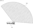
- FIG. 2 is a view illustrating a region of interest of a wide angle camera according to an exemplary embodiment of the present invention.
- two cameras 110 are mounted to be directed to both a ceiling and a front side using the wide angle camera in the mobile robot 10 as compared with the mobile robot of the related art which is directed to the ceiling or the front side so that in the mobile robot, both the ceiling and the front side may be set as regions of interest (ROI).
- ROI regions of interest
- the camera may photograph regions in both a horizontal direction and a vertical direction using the wide angle lens.
- both the ceiling and the front side are set as the regions of interest using the camera 110 mounted as described above, so that the feature points may be easily secured. Further, the position may be recognized even when it is difficult to find feature points and an obstacle at the front side may be recognized.
- the IMU 120 measures inertia information of the mobile robot, for example, information such as a position, a pose, and the like.
- the position recognizing unit 130 extracts an edge from a received stereo image.
- the edge may be extracted using approximated difference of Gaussian (ADoG) or a gradient.
- ADoG approximated difference of Gaussian
- the position recognizing unit 130 obtains gradients in a first axis direction and a second axis direction from each pixel of the received stereo image and extracts the edge based on the gradients in the first axis direction and the second axis direction.
- the first axis and the second axis may be different axes which are orthogonal to each other in a coordinate system of a plane of a stereo image.
- the first axis and the second axis may be an x-axis and a y-axis of an orthogonal coordinate system formed by the x-axis and the y-axis.
- an operation of the position recognizing unit 130 with the x-axis and the y-axis as the first axis and the second axis will be described.
- the operation of the position recognizing unit 130 which has been described with reference to the x-axis and the y-axis will be applied to the first axis and the second axis in the same way.
- the position recognizing unit 130 calculates a magnitude I m of the gradient using gradients I x and I y in the x-axis direction and the y-axis direction.
- the position recognizing unit 130 calculates an angle Ie of the gradient using gradients I x and I y in the x-axis direction and the y-axis direction.
- atan2(y,x) is an arctangent calculating function having two input variables and for example, may be calculated by the following equation.
- the position recognizing unit 130 finally extracts an edge image through a non-maximal suppression (NMS) process based on the calculated magnitude of the gradient I m and the angle of the gradient Ie of each pixel.
- NMS non-maximal suppression
- the position recognizing unit 130 selects a pixel having the largest magnitude I m of the gradient among adjacent pixels having the same angle with respect to the angle of the gradient Ie of the pixel as a maximal value.
- This process is applied to all pixels to extract an edge formed by one line.
- the position recognizing unit 130 extends a region to a predetermined number of pixels adjacent to the pixel located on the line which forms the edge and selects a pixel having a size which is equal to or larger than a predetermined threshold value in the extended region as an edge.
- the position recognizing unit 130 extends the region to two pixels which is the most adjacent to the pixel and selects all pixels having a size which is equal to or larger than the predetermined threshold value among pixels in the extended region as an edge.
- This process is applied to all pixels to extract a final edge image which is formed by a plurality of lines extended from the edge formed by one line through the NMS.
- the NMS (non-maximal suppression) process may use a non-maximal suppression technique introduced in " Canny, J., A Computational Approach To Edge Detection, IEEE Trans. Pattern Analysis and Machine Intelligence, 8(6):679 to 698, 1986 .” or may use other various types of non-maximal suppression techniques.
- ADoG approximated difference of Gaussian
- the present invention suggests a new method which calculates an integral image from an original image and performs a box smoothing process on the integral image to obtain a box smoothing image as the box smoothing result and then subtracts the original image from the box smoothing image to finally extract an edge image.
- a method of extracting an edge by the box smoothing process is referred to as an approximated difference of Gaussian (ADoG).
- the position recognizing unit 130 performs a smoothing processing on the received stereo image and obtains a smoothing image as the smoothing result.
- the position recognizing unit 130 compares the smoothing image and the original stereo image to extract an edge and estimates the current position of the mobile robot based on the extracted edge.
- the position recognizing unit 130 obtains an integral image from the stereo image, performs a box smoothing process on the obtained integral image to calculate a box smoothing image as the box smoothing processing result, compares the calculated box smoothing image and the original stereo image to extract the edge as a comparison result.
- the position recognizing unit 130 may include an integral image obtaining unit which obtains an integral image from the stereo image, a box smoothing image calculating unit which performs a box smoothing process on the obtained integral image to calculate a box smoothing image as the box smoothing processing result, and an edge extracting unit which compares the calculated box smoothing image and the original stereo image to extract the edge as a comparison result.
- the position recognizing unit may further include a position estimating unit.
- the position estimating unit may perform an operation of estimating a position of the mobile robot using the edge extracted by the position recognizing unit 130, which will be described in detail below.
- the integral image obtaining unit of position recognizing unit 130 obtains an integral image IntegImage from the stereo image orgImage by the following Equation.
- the smoothing image calculating unit of the position recognizing unit 130 performs a box blurring process or a box smoothing process on the obtained integral image to calculate a box smoothing image as the box smoothing processing result.
- the box smoothing may be a preprocessing process for removing a noise or extracting contour information, similarly to the Gaussian smoothing.
- box smoothing processing has been described as an example, but the present invention is not limited thereto and various smoothing processing technique, for example, a Gaussian smoothing may be applied.
- the final edge image may be extracted through the integral process, the smoothing process, and the subtraction process.
- the position recognizing unit 130 receives a stereo image from the wide angle camera 110 and recognizes a given space based on the received stereo image whenever the mobile robot moves a predetermined distance.
- FIG. 3 is a view illustrating a space recognizing process according to an exemplary embodiment of the present invention.
- the position recognizing unit 130 recognizes the given space whenever the mobile robot moves a predetermined distance or a new key frame is generated to create a database thereof.
- the position recognizing unit 130 reduces the received stereo image to have a predetermined size to be blurred.
- the predetermined size may be one eighth of the received stereo image.
- the position recognizing unit 130 reduces the received stereo image (a) and generates a blurred image (b).
- the position recognizing unit 130 encodes the blurred stereo image using a binary robust independent elementary features (BRIEF) binary descriptor to generate binary data as the encoding result.
- BRIEF binary descriptor may be encoded using a method introduced in ⁇ BRIEF ⁇ : Computing a Local Binary Descriptor Very Fast, M. Calonder, V. Lepetit, M. Ozuysal, T. Trzcinski, C. Strecha, and P. Fua IEEE Transactions on Pattern Analysis and Machine Intelligence 2012.
- the binary data may be generated to be 32 byte.
- FIG. 3C is a reference view illustrating the BRIEF binary descriptor.
- the position recognizing unit 130 compares the binary data generated as described above and data indicating an absolute position of the mobile robot in the previously stored key frame to recognize the current position with the absolute position when the absolute position is within a predetermined range as the comparison result.
- the reason why the BRIEF binary descriptor is used to recognize a space in the exemplary embodiment of the present invention is because an operating speed is much faster than that of descriptors which are used in the related art, such as SIFT or SURF.
- the position recognizing unit 130 receives the stereo image from the wide angle camera 110 to obtain first odometry information through a visual odometry based on the input stereo image and receives inertia information from the IMU 120 to obtain second odometry information through an internal odometry based on the input inertia information.
- the position recognizing unit 130 extracts a feature point from the stereo image to trace the extracted feature point and obtains the odometry information using the traced feature point.
- the feature point which is extracted during a preprocessing process is a corner.
- the position recognizing unit 130 performs stereo matching on an edge. That is, the position recognizing unit 130 extracts an edge from the stereo image and performs sparse stereo matching on the extracted edge.
- the sparse stereo matching is a concept which is distinguished from dense stereo matching.
- the sparse stereo matching is a matching method which sparsely and quickly matches stereo images, instead of calculating an exact matching result. Therefore, various methods of the related art for adjusting a matching interval or adjusting a search range for the matching may be used.
- FIG. 4 is a view illustrating uncertainty of a three-dimensional point according to an exemplary embodiment of the present invention.
- the position recognizing unit 130 sets uncertainty ⁇ according to a depth value obtained by a result of stereo matching and stores the uncertainty ⁇ in the DB.
- a focal length is very short so that the resolution is low. Therefore, the reliability of the obtained depth value is low so that the update is performed later.
- Equation 1 The uncertainty of the three-dimensional point obtained using two wide angle cameras is represented by Equation 1.
- ⁇ X 2 ⁇ XY ⁇ XZ ⁇ XY ⁇ Y 2 ⁇ YZ ⁇ XY ⁇ YZ ⁇ Z 2 indicates an uncertainty covariance ellipsoid and b indicates a distance between cameras, x, y, z indicate a coordinate system of the left image camera and x', y', z' indicates a coordinate system of the right image camera.
- (c, r) and (c', r') indicate coordinates of matching pixels in the left camera and the right camera, f and f indicate focal distances of the left camera and the right camera.
- ⁇ r , ⁇ c represent the uncertainty when the feature point is extracted as axes and ro and c 0 represent the optical axis of the camera by a camera coordinate system. Further, d is a difference generated when the feature point is projected to the left side and the right side and generally referred to as a disparity.
- pixels which are stored in the key frame are projected to the current image to find the most similar pixel and update the depth value.
- the update may be performed by applying a general Bayesian rule.
- erroneous information is input due to various variables, specifically, a moving obstacle or a block while the mobile robot is moving and thus a depth value obtained based on erroneous information may have an outlier.
- a variable no_success is increased by one and when the obtained depth value is larger than 1 ⁇ , the variable no_failure is increased by one. Thereafter, only when the reliability no_success/(no_success + no_failure) is larger than a specific value, the depth value is used to recognize the position.
- Equation 2 The Bayesian rule which is used to update the depth value is represented by Equation 2.
- the x-value and the y-value vary depending on z. Therefore, x, y, and z are updated so that the position is figured out and the updated x, y, z are used to figure the position of the camera in the other way.
- FIG. 5 is a view illustrating three-dimensional information on an edge according to an exemplary embodiment of the present invention.
- FIG. 5(a) is an image representing a depth value which is projected to the left image camera
- FIG. 5(b) is an image representing a depth value which is projected to the right image camera
- FIG. 5(c) is an image representing a depth value obtained through the updating process
- FIG. 5(d) is an image representing projection to a matching point and a depth value.
- the three-dimensional information on the edge may be consistently obtained.
- the information of the IMU is very important in a situation where it is difficult to recognize the environment by the camera.
- bias is significantly deformed or hardly estimated.
- the bias is obtained by stopping the robot for a moment and taking an average. In this case, the user may think that the mobile robot is not intelligent and the working speed is lowered.
- the position recognizing unit 130 updates the bias during the movement.
- ⁇ g is an angular velocity obtained by a gyro sensor and ⁇ c is an angular velocity obtained by a wide angle stereo vision.
- ⁇ e may be a bias.
- the odometry information using the IMU may maintain a predetermined level of accuracy using the optimal bias.
- the position recognizing unit 130 estimates current state information, for example, a pose or a position based on one odometry information selected from first odometry information and second odometry information.
- the position recognizing unit 130 performs stereo matching between the stereo images using the edge extracted from the stereo image to calculate the disparity value or the depth value in the pixel included in the stereo image and estimates the current position of the mobile robot using the calculated disparity value or the depth value. That is, the stereo matching between the stereo images is performed on the pixel corresponding to the edge extracted from the stereo image to calculate the disparity value or the depth value and the current position of the mobile robot is estimated using the disparity value or the depth value, the optical axis information of the camera, the focal distance information, distance information between the stereo cameras.
- a three-dimensional coordinate may be restored in the pixel and the position of the mobile robot may be relatively figured out through the three-dimensional coordinate in the pixels included in the stereo image.
- the restored three-dimensional coordinates (x, y, z) is b u ⁇ u 0 d b v ⁇ v 0 d fb d .
- a method of figuring out the position of the object from which the stereo image is obtained using the depth value of the stereo image may use various techniques of the related art.
- a seed may be set for a pixel selected from the edge of the image. Further, the seed may be set for pixels in which three-dimensional coordinates are restored as described above.
- the seed may include at least one of an image coordinate, a disparity, a variance of disparity, a pixel value, and a gradient direction and magnitude.
- the position recognizing unit 130 may predict the current position using at least one key frame among the previously stored key frame set based on the status information estimated as described above.
- the key frame may be a set of seeds including status information of the mobile robot which is periodically measured and the relationship between the key frame K and the seed s is represented by Equation 6.
- K s 0 , s 1 , ... , s n
- the position recognition of the mobile robot may be predicted using a registered key frame and may be a process of calculating how much the mobile robot moves with respect to the given key frame.
- prj() indicates a function of returning the projection coordinate of the seed to the camera.
- the projection coordinate of the seed calculated by Equation 7 is gathered to an edge in the image, which is enabled by appropriate R and T. That is, as the position recognizing result is more accurate, the projection of the coordinate restored through all seeds to the current camera is gathered onto the edge.
- the position recognizing unit 130 includes a cost calculating unit 131 which projects each seed in the given key frame to calculate a cost in the current position of the mobile robot using the projected seed, a direction calculating unit 132 which calculates a direction in the current position of the mobile robot in which the cost is increased, a parameter update unit 133 which updates the status parameter in a position to be updated along the direction in which the cost is increased, and a position estimating unit 134 which estimates a position having the highest cost as the current position of the mobile robot based on the updated status parameter.
- FIG. 6 is a view illustrating a position recognizing concept according to an exemplary embodiment of the present invention.
- Equation 3 when Equation 3 is used, the cost is changed by the parameter R and T. As a result, when the parameters R and T are updated along the direction in which the cost is increased, a very accurate position may be obtained.
- the accurate position is recognized by updating the parameters R and T using gradient descent, which is referred to as edge based refinement.
- the gradient descending method is one of representative methods which apply a concept of differentiation to optimization. According to the gradient descent, to find a maximum point of an arbitrary function, it moves to a negative direction of the gradient in the current position.
- FIG. 7 is a view illustrating a position recognizing process according to an exemplary embodiment of the present invention.
- the position recognizing unit 130 obtains an image at a present time in step S710, extracts an edge from the obtained image in step S712, and calculates a magnitude of the extracted edge in step S714.
- the position recognizing unit 130 calculates a gradient in each pixel of an image including the edge in a first axis direction and a second axis direction, calculates a magnitude of the gradient using the calculated gradient in the first axis direction and the second axis direction, and sets the calculated magnitude of the gradient as a size of the edge.
- first axis and the second axis may be different axes which are orthogonal to each other in a coordinate system of an image plane including the edge.
- the first axis and the second axis may be different axes which are orthogonal to each other in a coordinate system of an image plane including the edge.
- the first axis and the second axis may be an x-axis and a y-axis of an orthogonal coordinate system formed by the x-axis and the y-axis.
- the position recognizing unit 130 obtains the gradients I x and I y in the x-axis direction and the y-axis direction in each pixel of the image and calculates a gradient magnitude I m using the obtained gradients I x and I y in the x-axis direction and the y-axis direction, as represented in Equation 8.
- the magnitude of the gradient may be considered as the size of the edge.
- the position recognizing unit 130 projects each seed in the selected key frame to calculate a sum of edge sizes, that is, a cost and updates status parameters indicating rotation and movement of the camera along a direction where the calculated cost is increased to estimate the position having the highest cost as the current position.
- the position recognizing unit 130 calculates a cost in the position using the projected seeds.
- the above-described operation of the position recognizing unit 130 may be performed by the cost calculating unit 131.
- f() is a cost function and is a function of returning the edge size in the image.
- the position recognizing unit 130 calculates a direction in which the cost is increased from T c i in the current position x i .
- the direction in which the cost is increased is represented by Equation 11.
- the above-described operation of the position recognizing unit 130 may be performed by the direction calculating unit 132. ⁇ f prj T c i P i ⁇ T c i
- the position recognizing unit 130 updates T c i+1 in the position x i+1 which is to be updated along the direction in which the cost is increased and the status parameter T c i+1 in the position to be updated is represented by Equation 12.
- the above-described operation of the position recognizing unit 130 may be performed by the parameter update unit 133.
- k is an arbitrary constant which adjusts a convergence speed and is appropriately adjusted in accordance with convergence.
- the position recognizing unit 130 checks whether to satisfy a predetermined repetition condition to re-estimate the position using a cost calculated in the position to be updated and a cost calculated in the previous position.
- the repetition condition includes whether a variation between a cost calculated in the position to be updated to determine whether to update and a cost calculated in the previous position is within a predetermined threshold value.
- the position recognizing unit 130 calculates the variation between the cost calculated in the position to be updated and the cost calculated in the previous position and compares whether the calculated variation is equal to or larger than the predetermined threshold value.
- the position recognizing unit 130 selects the position to be updated as a candidate position to check a coordinate of the selected candidate position.
- the position recognizing unit 130 calculates a direction in which the cost is increased in the candidate position and updates the status parameters along the direction in which the cost is increased as the calculation result to perform additional position estimation based thereon.
- the position recognizing unit 130 determines that the position variation through the update of the status parameters is very insignificant so that the position is not changed and selects the previous position as a final position of the mobile robot and ends subsequent processes.
- the position estimating operation of the position recognizing unit 130 may be performed by the position estimating unit 134.
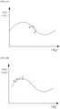
- FIGS. 8A and 8B are views illustrating a position recognizing principle according to an exemplary embodiment of the present invention.
- FIG. 8A a cost according to the position of the mobile robot is illustrated.
- the position B to be updated in the direction in which the cost is increased from the current position A is illustrated.
- FIG. 8B a cost according to the position of the mobile robot is illustrated. In the drawing, since the cost is maximal in the current position C, so that the current position is not updated to the position D.
- a process of projecting the seed in the given key frame based on the predicted status information to calculate the cost as the projection result and updating the status parameters along the direction in which the calculated cost is increased to estimate the position based on the updated status parameter is repeatedly performed until it is determined that the position is scarcely changed.
- the obstacle sensing unit 140 receives the stereo image from the wide angle camera 110 to extract a predetermined number of horizontal lines in the received stereo image.
- the predetermined number is at least two and desirably three.
- the obstacle sensing unit 140 performs dense stereo matching along the extracted horizontal line to obtain distance information to the obstacle as the result.
- the dense stereo matching is a concept which is distinguished from sparse stereo matching and is a matching method which calculates an exact matching result when matching is performed between stereo images.
- various methods of the related art for adjusting a matching interval or adjusting a search range for the matching may be used.
- FIG. 9 is a view illustrating an obstacle sensing process according to an exemplary embodiment of the present invention.
- the obstacle sensing unit 140 performs highly dense stereo matching based on the received left and right stereo images as illustrated in FIGS. 9(a) and 9(b) to calculate a depth value as the result.
- the depth value calculated as described above is represented by gray scales.
- FIG. 9(c) illustrates a linear region L which is used to sense the obstacle.
- a depth value is extracted only from a partial region.
- the map creating unit 150 is provided with current position information which is estimated by the position recognizing unit 130, reconstructs a pose graph based on position information, and updates the previously stored key frame set based on the reconstructed pose graph.
- the DB 160 stores the key frame set generated in accordance with movement of the mobile robot.
- a method of recognizing a position of a mobile robot includes receiving at least one pair of stereo images obtained using a camera provided in the mobile robot; and extracting an edge from the received stereo images to project each seed in a given key frame based on the extracted edge, updating a status parameter indicating rotation and movement of the camera along a direction in which the cost calculated is increased as the projection result and estimating the position of the mobile robot using the updated result.
- the method of recognizing a position of a mobile robot may operate by the same way as the apparatus of recognizing a position of the mobile robot described above. Therefore, redundant parts will be omitted or simply described.
- each seed in the given key frame is projected to calculate a cost in the current position of the mobile robot using the projected seed, a direction in the current position of the mobile robot in which the cost is increased is calculated, the status parameter in a position to be updated along the direction in which the cost is increased is updated, and a position having the highest cost is estimated as the current position of the mobile robot based on the updated status parameter.
- FIG. 10 is a view illustrating a method for recognizing a position of a mobile robot according to an exemplary embodiment of the present invention.
- a position recognizing apparatus when an apparatus for recognizing the position of the mobile robot (hereinafter, referred to as a position recognizing apparatus) according to an exemplary embodiment of the present invention receives a stereo image from the wide angle camera in step S910, extracts a feature point from the input stereo image and consistently traces the extracted feature point in the unit of frame in step S920.
- the position recognizing apparatus may remove a moving object in the stereo image in step S930.
- the position recognizing apparatus compares the current frame and the last n-th frame to remove an inconsistent feature which may be determined as a moving object as the comparison result.
- the position recognizing apparatus performs visual odometry based on the traced feature point to obtain first odometry information as the result in step S940 and obtain second odometry information through inertia information based internal odometry in step S942.
- the position recognizing apparatus selects one odometry information between first odometry information and second odometry information in step S950 and predicts status information using the selected odometry information and pose information in step S960.
- the position recognizing apparatus selects the first odometry information when the first odometry information satisfies a predetermined condition and selects the second odometry information when the first odometry information does not satisfy the predetermined condition.
- the odometry information for example, a change rate of the position information is within a predetermined threshold value.
- the position recognizing apparatus searches at least one key frame among the previously stored key frame set based on the predicted status information in step S970 and estimates the current position using at least one searched key frame in step S980.
- the position recognizing apparatus projects each seed in a given key frame to calculate a cost indicating a sum of edge sizes as the projecting result and a status parameter indicating rotation and update movement of a camera along a direction in which the calculated cost is increased to estimate a position having the highest cost as a current position, thereby calculating a final position.
- the position may be accurately estimated as the number of adjacent key frames is large.
- the position recognizing apparatus may be applied to autonomous cleaning robot or service robot.
- the cleaning robot autonomously moves in an indoor environment or an outdoor environment.
- the cleaning robot meets various obstacles such as a wall, a guardrail, a desk, or furniture and the autonomous cleaning robot determines a moving route using the position of the robot in the cleaning area and the position of the obstacle and moves along the moving route.
- the autonomous cleaning robot includes the stereo camera, specifically, a wide angle stereo camera as an image capturing unit to obtain an external image. By doing this, the autonomous cleaning robot estimates its own position, determines the moving route, and moves using information on the external environment obtained thereby, specifically, using the feature point related to an edge.
- the exemplary embodiment may be used to estimate its own position on the constructed lattice map, estimate a position of the obstacle, determine a movement route to avoid collision with the obstacle using the estimated position relationship or determine an optimal route.
- SLAM simultaneous localization and map-building
- the odometry information may be data which is used to estimate the positional change of the mobile robot in accordance with the time.
- the odometry information may be information obtained from a wheel mounted in the mobile robot or rotary encoders in a legged joint.
- the status information such as movement distance of the mobile robot or a number of rotations of the wheel may be calculated using the odometry information.
- the space where the mobile robot is currently located may be understood through the status information so that the odometry information may be used to determine the key frame during the image processing.
- the position recognizing method according to the exemplary embodiment of the present invention may be implemented as computer readable software and the software may be executed in a processor mounted in the autonomous cleaning robot.
- the present invention is not limited to the exemplary embodiment.
- one or more of all of the components may be selectively combined to be operated within a scope of the present invention.
- all of the components may be implemented as one independent hardware but a part or all of the components are selectively combined to be implemented as a computer program which includes a program module which performs a part or all of functions combined in one or plural hardwares.
- a computer program may be stored in a computer readable media such as a USB memory, a CD disk, or a flash memory to be read and executed by a computer to implement the exemplary embodiment of the present invention.
- the recording media of the computer program may include a magnetic recording medium, an optical recording medium, or a carrier wave medium.
Landscapes
- Engineering & Computer Science (AREA)
- Physics & Mathematics (AREA)
- General Physics & Mathematics (AREA)
- Radar, Positioning & Navigation (AREA)
- Remote Sensing (AREA)
- Multimedia (AREA)
- Computer Vision & Pattern Recognition (AREA)
- Automation & Control Theory (AREA)
- Theoretical Computer Science (AREA)
- Aviation & Aerospace Engineering (AREA)
- Mechanical Engineering (AREA)
- Robotics (AREA)
- Electromagnetism (AREA)
- Human Computer Interaction (AREA)
- Signal Processing (AREA)
- Length Measuring Devices By Optical Means (AREA)
- Image Analysis (AREA)
- Manipulator (AREA)
- Image Processing (AREA)
Applications Claiming Priority (2)
| Application Number | Priority Date | Filing Date | Title |
|---|---|---|---|
| KR20140073708 | 2014-06-17 | ||
| PCT/KR2015/006155 WO2015194866A1 (fr) | 2014-06-17 | 2015-06-17 | Dispositif et procédé permettant de reconnaître un emplacement d'un robot mobile au moyen d'un réajustage basé sur les bords |
Publications (2)
| Publication Number | Publication Date |
|---|---|
| EP3159126A1 true EP3159126A1 (fr) | 2017-04-26 |
| EP3159126A4 EP3159126A4 (fr) | 2018-05-30 |
Family
ID=61628060
Family Applications (1)
| Application Number | Title | Priority Date | Filing Date |
|---|---|---|---|
| EP15810535.3A Withdrawn EP3159126A4 (fr) | 2014-06-17 | 2015-06-17 | Dispositif et procédé permettant de reconnaître un emplacement d'un robot mobile au moyen d'un réajustage basé sur les bords |
Country Status (4)
| Country | Link |
|---|---|
| US (1) | US10399228B2 (fr) |
| EP (1) | EP3159126A4 (fr) |
| KR (1) | KR101776621B1 (fr) |
| WO (1) | WO2015194866A1 (fr) |
Cited By (2)
| Publication number | Priority date | Publication date | Assignee | Title |
|---|---|---|---|---|
| CN109584856A (zh) * | 2018-12-06 | 2019-04-05 | 宁波可凡电器有限公司 | 渐进式声音屏蔽机构 |
| EP3686703A4 (fr) * | 2017-08-02 | 2020-12-23 | Ankobot (Shenzhen) Smart Technologies Co., Ltd. | Procédé, appareil et système de commande destinés à un robot, et robot correspondant |
Families Citing this family (17)
| Publication number | Priority date | Publication date | Assignee | Title |
|---|---|---|---|---|
| US10078908B2 (en) * | 2016-08-12 | 2018-09-18 | Elite Robotics | Determination of relative positions |
| US10962647B2 (en) | 2016-11-30 | 2021-03-30 | Yujin Robot Co., Ltd. | Lidar apparatus based on time of flight and moving object |
| US11579298B2 (en) | 2017-09-20 | 2023-02-14 | Yujin Robot Co., Ltd. | Hybrid sensor and compact Lidar sensor |
| US10776652B2 (en) * | 2017-09-28 | 2020-09-15 | Baidu Usa Llc | Systems and methods to improve visual feature detection using motion-related data |
| CN107553497B (zh) * | 2017-10-20 | 2023-12-22 | 苏州瑞得恩光能科技有限公司 | 太阳能面板清扫机器人的边缘定位装置及其定位方法 |
| CN107907131B (zh) * | 2017-11-10 | 2019-12-13 | 珊口(上海)智能科技有限公司 | 定位系统、方法及所适用的机器人 |
| CN107845080B (zh) * | 2017-11-24 | 2020-03-20 | 信雅达系统工程股份有限公司 | 卡片图像增强方法 |
| CN111466110B (zh) * | 2017-12-12 | 2023-05-09 | 索尼公司 | 边缘计算重定位 |
| KR102044703B1 (ko) * | 2018-02-14 | 2019-12-02 | 엘지전자 주식회사 | 자율주행 차량 및 그 제어 방법 |
| US11874399B2 (en) | 2018-05-16 | 2024-01-16 | Yujin Robot Co., Ltd. | 3D scanning LIDAR sensor |
| KR102547274B1 (ko) | 2018-09-13 | 2023-06-23 | 주식회사 케이티 | 이동 로봇 및 이의 위치 인식 방법 |
| EP3633955B1 (fr) * | 2018-10-04 | 2023-10-25 | Nokia Solutions and Networks Oy | Appareil, procédé et programme informatique pour contrôler la capacité d'un réseau sans fil |
| US11295532B2 (en) | 2018-11-15 | 2022-04-05 | Samsung Electronics Co., Ltd. | Method and apparatus for aligning 3D model |
| US10782137B2 (en) * | 2019-01-28 | 2020-09-22 | Qfeeltech (Beijing) Co., Ltd. | Methods, apparatus, and systems for localization and mapping |
| CN113043282B (zh) * | 2019-12-12 | 2022-03-29 | 牧今科技 | 用于物体检测或机器人交互规划的方法和系统 |
| CN111818525B (zh) * | 2020-07-13 | 2021-10-26 | 清华大学 | 面向空间信息网络的密钥更新方法和系统 |
| CN116880511B (zh) * | 2023-08-24 | 2024-05-28 | 烟台大学 | 含姿态规划的轮式移动机器人位置控制方法、系统及设备 |
Family Cites Families (12)
| Publication number | Priority date | Publication date | Assignee | Title |
|---|---|---|---|---|
| KR100478452B1 (ko) | 2002-06-12 | 2005-03-23 | 삼성전자주식회사 | 이동 로봇의 위치 및 방향 인식 장치 및 방법 |
| US7110602B2 (en) * | 2002-08-21 | 2006-09-19 | Raytheon Company | System and method for detection of image edges using a polar algorithm process |
| KR100834577B1 (ko) | 2006-12-07 | 2008-06-02 | 한국전자통신연구원 | 스테레오 비전 처리를 통해 목표물 검색 및 추종 방법, 및이를 적용한 가정용 지능형 서비스 로봇 장치 |
| KR101581197B1 (ko) | 2009-01-06 | 2015-12-30 | 삼성전자주식회사 | 로봇 및 그 제어방법 |
| KR101513639B1 (ko) * | 2009-04-30 | 2015-04-20 | 엘지전자 주식회사 | 이동 로봇, 로봇 청소기 및 이동 로봇의 각도 검출 방법 |
| KR101618030B1 (ko) * | 2009-07-28 | 2016-05-09 | 주식회사 유진로봇 | 이동 로봇의 위치 인식 및 주행 제어 방법과 이를 이용한 이동 로봇 |
| KR101083394B1 (ko) | 2009-10-30 | 2011-11-14 | 주식회사 유진로봇 | 이동 로봇의 위치 인식을 위한 지도 생성 및 갱신 방법 |
| KR101167627B1 (ko) | 2010-02-25 | 2012-07-23 | 연세대학교 산학협력단 | 이동 로봇의 위치 및 지도의 이중 보정 장치 및 방법 |
| KR20120070291A (ko) | 2010-12-21 | 2012-06-29 | 삼성전자주식회사 | 보행 로봇 및 그의 동시 위치 인식 및 지도 작성 방법 |
| KR20130004674A (ko) | 2011-07-04 | 2013-01-14 | 주식회사 스마트센스테크놀러지 | 다 수개 지시물체의 위치인식장치 |
| JP2014022843A (ja) * | 2012-07-13 | 2014-02-03 | Canon Inc | 監視カメラシステム及び監視カメラシステムの制御方法 |
| JP5895955B2 (ja) * | 2014-02-07 | 2016-03-30 | トヨタ自動車株式会社 | 車線境界線検出装置 |
-
2015
- 2015-06-17 KR KR1020150086219A patent/KR101776621B1/ko active Active
- 2015-06-17 EP EP15810535.3A patent/EP3159126A4/fr not_active Withdrawn
- 2015-06-17 WO PCT/KR2015/006155 patent/WO2015194866A1/fr not_active Ceased
-
2016
- 2016-12-16 US US15/382,450 patent/US10399228B2/en active Active
Cited By (3)
| Publication number | Priority date | Publication date | Assignee | Title |
|---|---|---|---|---|
| EP3686703A4 (fr) * | 2017-08-02 | 2020-12-23 | Ankobot (Shenzhen) Smart Technologies Co., Ltd. | Procédé, appareil et système de commande destinés à un robot, et robot correspondant |
| CN109584856A (zh) * | 2018-12-06 | 2019-04-05 | 宁波可凡电器有限公司 | 渐进式声音屏蔽机构 |
| CN109584856B (zh) * | 2018-12-06 | 2022-02-08 | 宁波顺超轴承有限公司 | 渐进式声音屏蔽机构 |
Also Published As
| Publication number | Publication date |
|---|---|
| US20170151675A1 (en) | 2017-06-01 |
| KR101776621B1 (ko) | 2017-09-11 |
| US10399228B2 (en) | 2019-09-03 |
| WO2015194866A1 (fr) | 2015-12-23 |
| EP3159126A4 (fr) | 2018-05-30 |
| KR20150144727A (ko) | 2015-12-28 |
Similar Documents
| Publication | Publication Date | Title |
|---|---|---|
| US10399228B2 (en) | Apparatus for recognizing position of mobile robot using edge based refinement and method thereof | |
| US10275649B2 (en) | Apparatus of recognizing position of mobile robot using direct tracking and method thereof | |
| EP3159121A1 (fr) | Dispositif de mise à jour de carte de robot mobile et procédé associé | |
| US10307910B2 (en) | Apparatus of recognizing position of mobile robot using search based correlative matching and method thereof | |
| US10133278B2 (en) | Apparatus of controlling movement of mobile robot mounted with wide angle camera and method thereof | |
| US12504286B2 (en) | Simultaneous location and mapping (SLAM) using dual event cameras | |
| US10762643B2 (en) | Method for evaluating image data of a vehicle camera | |
| KR101072876B1 (ko) | 이동 로봇에서 자신의 위치를 추정하기 위한 방법 및 장치 | |
| KR20220085682A (ko) | 전방향 영상센서 및 관성측정센서의 자세추정 융합 방법 및 시스템 | |
| CN120252680A (zh) | 一种基于多传感器融合的slam定位方法及系统 | |
| KR102831462B1 (ko) | 차량의 객체 검출 장치 및 방법 | |
| CN120471954A (zh) | 一种基于视觉slam的运动目标跟踪方法 | |
| CN116558526B (zh) | 基于视觉slam的动态物体识别避障导航方法及系统 | |
| US12387360B2 (en) | Apparatus and method for estimating uncertainty of image coordinate | |
| Salimzadeh | Visual State Estimation for Autonomous Navigation | |
| Itu et al. | Machine learning based automatic extrinsic calibration of an onboard monocular camera for driving assistance applications on smart mobile devices | |
| KR20260019069A (ko) | 인식률 및 측정 범위 향상을 위한 센서 융합 및 데이터 처리 장치 및 방법 | |
| Roberts | Optical flow templates for mobile robot environment understanding | |
| Guizilini et al. | Multi-task learning of visual odometry estimators |
Legal Events
| Date | Code | Title | Description |
|---|---|---|---|
| STAA | Information on the status of an ep patent application or granted ep patent |
Free format text: STATUS: THE INTERNATIONAL PUBLICATION HAS BEEN MADE |
|
| PUAI | Public reference made under article 153(3) epc to a published international application that has entered the european phase |
Free format text: ORIGINAL CODE: 0009012 |
|
| STAA | Information on the status of an ep patent application or granted ep patent |
Free format text: STATUS: REQUEST FOR EXAMINATION WAS MADE |
|
| 17P | Request for examination filed |
Effective date: 20170117 |
|
| AK | Designated contracting states |
Kind code of ref document: A1 Designated state(s): AL AT BE BG CH CY CZ DE DK EE ES FI FR GB GR HR HU IE IS IT LI LT LU LV MC MK MT NL NO PL PT RO RS SE SI SK SM TR |
|
| AX | Request for extension of the european patent |
Extension state: BA ME |
|
| DAV | Request for validation of the european patent (deleted) | ||
| DAX | Request for extension of the european patent (deleted) | ||
| A4 | Supplementary search report drawn up and despatched |
Effective date: 20180430 |
|
| RIC1 | Information provided on ipc code assigned before grant |
Ipc: G06K 9/46 20060101ALI20180423BHEP Ipc: G06K 9/00 20060101ALI20180423BHEP Ipc: G05D 1/02 20060101AFI20180423BHEP Ipc: G06T 7/00 20170101ALI20180423BHEP |
|
| STAA | Information on the status of an ep patent application or granted ep patent |
Free format text: STATUS: EXAMINATION IS IN PROGRESS |
|
| 17Q | First examination report despatched |
Effective date: 20191213 |
|
| STAA | Information on the status of an ep patent application or granted ep patent |
Free format text: STATUS: THE APPLICATION HAS BEEN WITHDRAWN |
|
| 18W | Application withdrawn |
Effective date: 20221010 |