EP3159229B1 - Dispositif de stabilisation, système comprenant un tel dispositif de stabilisation et procédé de stabilisation d'un poids lourd ou d'une remorque - Google Patents
Dispositif de stabilisation, système comprenant un tel dispositif de stabilisation et procédé de stabilisation d'un poids lourd ou d'une remorque Download PDFInfo
- Publication number
- EP3159229B1 EP3159229B1 EP16192814.8A EP16192814A EP3159229B1 EP 3159229 B1 EP3159229 B1 EP 3159229B1 EP 16192814 A EP16192814 A EP 16192814A EP 3159229 B1 EP3159229 B1 EP 3159229B1
- Authority
- EP
- European Patent Office
- Prior art keywords
- semi
- trailer
- truck
- stability device
- support
- Prior art date
- Legal status (The legal status is an assumption and is not a legal conclusion. Google has not performed a legal analysis and makes no representation as to the accuracy of the status listed.)
- Active
Links
Images
Classifications
-
- B—PERFORMING OPERATIONS; TRANSPORTING
- B60—VEHICLES IN GENERAL
- B60T—VEHICLE BRAKE CONTROL SYSTEMS OR PARTS THEREOF; BRAKE CONTROL SYSTEMS OR PARTS THEREOF, IN GENERAL; ARRANGEMENT OF BRAKING ELEMENTS ON VEHICLES IN GENERAL; PORTABLE DEVICES FOR PREVENTING UNWANTED MOVEMENT OF VEHICLES; VEHICLE MODIFICATIONS TO FACILITATE COOLING OF BRAKES
- B60T3/00—Portable devices for preventing unwanted movement of vehicles, e.g. chocks
Definitions
- the present invention relates to a stand-still device according to the preamble of the main claim. Furthermore, the present invention relates to a system comprising a semi-trailer and a generic stability device, and the present invention relates to a method for stability of a truck or a preferably on a loading and / or Entladestrom semitrailer.
- Object of the present invention is therefore to improve a stand-still device according to the preamble of the main claim so that this with a simple and inexpensive construction, with ease of use, high stability and reliable in the field of (rear) landing gear of a semitrailer or truck for supporting the same can be used, in particular under difficult loading and environmental conditions a reliable Attachment of the safety device and subsequent support is to be ensured.
- a support and stability system consisting of a stand-still device in conjunction with a truck or semitrailer is to provide, and there is a method for stability of a preferably on a loading and / or Entladestrom stationary truck or semi-trailer to create, which has the disadvantages described overcomes and creates in the task-appropriate way improvements.
- the stand-securing device on the (adjustable length) stand on the base opposite end portion, a parallel to the support surface extending support support for a support portion of the truck or the semitrailer, which support support are additionally assigned stop means, the allows lateral application to the support section (or to an adjacent attachment of the semitrailer suitable for locating a support point).
- the slings are characterized by the fact that they extend vertically at least in sections from the support surface, so that in the context of the invention on the one hand support of the truck or semi-trailer is made possible by means of its support portion from below, but at the same time the slings invention precise and reliable introduction or localization of this support point.
- the present invention obviously also lends itself to handling for vehicles whose support section is offset inwardly from a side wall so as to provide lateral access to the location and subsequent ones Support is simplified even under these difficult installation conditions and can be made safe to operate.
- this technology is also connected to the stand associated transport, which can be further preferably designed as wheelset, pair of wheels or the like.
- the invention then provides that, by pivoting, tilting or the like, manual handling of the safety device, the transport means for allowing the device to roll would be placed on an underlying floor, thus allowing for the intended ease of manual handling and movement an upright securing position (truck or semi-trailer securing state) with lying on an underlying floor bearing surface of the stand according to this development, the means of transport, that is to say the wheelset, are at a distance from the underlying ground or at least do not touch them non-positively, so that in this respect the standing-securing operation is uninfluenced by the means of transport.
- the elongated, lever or rod-like guide means of the preferred development facilitate this transport and tilting, so that in particular the handling and operating personnel handling the stand-still device according to the invention is simplified.
- the length adjustable and thus adapted to adapt to be supported height of the support portion of a truck or semitrailer adjustable stand telescopically, with a plurality of intermeshing support elements together suitably or disassembled and detachable according to preferred embodiments of predetermined locking or locking positions can be connected to each other.
- a further development of this principle or alternative embodiment of the invention provides a winch and / or spindle drive for effecting the length adjustment of the stand before, in turn, in addition synergistically provided further and manually manageable lever or the rod, in addition to its role as a guide means for the Moving the stability device, as a crank or the like. Actuating means for such a spindle or winch can be configured.
- the lever or the rod suitably crank-shaped realized, brought into a corresponding operating position and allows the operator the intended height adjustment (usually at the site).
- a height adjustment can take place both before an approach to the support section, as well as in already introduced stability (ie already standing under the support).
- a particularly preferred embodiment of the invention takes into account the particular geometrical conditions at the intended site of use immediately adjacent to a (rear) chassis of a truck or semitrailer: due to the spatial narrowness normally encountered there for intended lateral access, i. Feeding the stability device from a direction transverse to the longitudinal extent and direction, insofar parallel to an axial direction, according to preferred Weite Strukturen of the invention is simplified in that the transverse extent of the support support according to the invention including stop means (ie, preferably of these technologies realizing elbow) is much narrower than a Transverse extension of the support causing the underlying soil stand.
- transverse extent is to be understood as a dimensional specification such that in a mounting relationship with the truck or semitrailer, the transverse extent runs parallel to the side wall of the vehicle, thus along the longitudinal direction and direction of travel.
- the preferred realization of the invention provides that the transverse extent of the supporting support together with the stop means is less than 40%, preferably less than 30% and even more preferably less than 25% of a maximum transverse extension of the stand, (wherein the respective transverse extensions then run parallel to one another) ; an alternative dimensioning in the context of developments of the invention sets the transverse extent of the support surface and the stop means with these proportions in relation to a wheel distance of yellowigesdorf the transport means for the stability device realizing wheels.
- the present invention achieves in a surprisingly simple and elegant manner the goal, with simple handling and highly reliable positioning of the stability device in the region of a (in particular rear or rear side) chassis of a Truck or semi-trailer below a (usually offset inward) section to achieve, although, not least by numerous side of the vehicle provided truck attachments, narrow access and a support point difficult to recognize and approach.
- the device according to the invention is structurally simple to implement, allows the synergistic and in turn optimized multiple use of handling agents and opens up the stability even modern, spring-loaded (and prone to adverse compression) vehicles completely new operating options in loading and unloading ,
- the intended consequence is that in particular disadvantageous damage caused by the undesired compression of the charging station (eg the loading dock) can be effectively excluded.
- a step formation which is problematic due to (load-dependent) compression and can be avoided, for instance, for forklifts or the like. Chargers can be avoided.
- the height adjustment of the adjustable-length trained stand done until the support surface for effecting the support reaches the support portion (from below), so that in particular at this time the tractor can be decoupled or otherwise a load or a lowering of the vehicle with respect to the support pad is made possible.
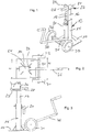
- FIGS. 1 to 4 first clarify the essential structural-mechanical components of the stability of the device shown First exemplary embodiment:
- a telescopically extendable stand 12 is permanently fixed by welding on a bottom plate 10 made of (galvanized) steel material forming an underlying ground and is mechanically supported by struts, which form an inner tube 16 guided in a cross-sectionally rectangular outer tube 14. in turn provided at regular intervals locking holes 18 which can cooperate with manually operable locking means 20 of the outer tube so that according to a relative distance of the holes 18 predetermined height positions can be fixed.
- an angle piece 22 is permanently connected by welding, which on the one hand forms a support surface 24 (which extends essentially parallel to the bottom plate 10), on the other hand realizes the stop means according to the invention in the form of a portion 26 extending vertically therefrom.
- the section 26 is associated with a handle portion 28 for manual handling of the device.
- FIGS. 1 to 4 let in addition recognize that in the mounted state of a base realizing base plate 10 is assigned a wheel consisting of a pair of wheels 30, 32 with connecting axle 34 so that in a plane support condition of the plate 10 on an underlying ground, the wheels 30, 32 just not touch the ground forcefully, the wheelset 30, 32 is fixed to the bottom plate 10 so that by tilting or tilting about an axis 34 corresponding tilting axis, the entire device by means of the wheelset 30, 32 can be moved, as in such a tilted Condition the wheels touch the underlying ground, while the bottom plate 10 is lifted from the ground.
- This tilting and a subsequent manual procedure of the thus tilted device is facilitated by a crank-like designed rocker arm 36, which in the in the FIGS.
- the transverse extent B1 marks a maximum width of the assembly 22, while B2 describes a maximum width and transverse extent of the bottom plate 10.
- the ratio B1: B2 ⁇ 25% so that the present invention, which will be described below with reference to Fig. 4 to explain the context of use is particularly favorable geeinget with its upper end for the support pad and the stop for insertion into a support portion of a saddle even under tight space conditions, while the bottom side by the much wider plate 10 always the best possible support and a reliable force entry in the underlying soil is guaranteed.
- Comparable favorable proportions are between the transverse extent B1 of the support surface including stop on the one hand and a distance of the wheels 30, 32 on the other hand, in the Fig. 2 designated B3, which indicates the inner dimension of the wheelbase.
- B3 indicates the inner dimension of the wheelbase.
- the ratio is B1: B3 less than 25%, again to enable the favorable operating characteristics, on the one hand the smallest possible contact contact on the semi-trailer combined with the broadest possible bottom-side guide and support (or favorable displacement properties of the device by the far outside starting wheel pair 30th , 32).
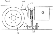
- FIGS. 1 to 3 While indicated by the reference numeral 40 and dashed lines in Fig. 4 a stop support position for a (cross-sectionally shown) support portion of a semitrailer is shown, illustrates the Fig. 4 in the side view this context of use in the overall picture. It becomes clear that the standby device of FIGS. 1 to 3 , not least by the favorable Quererstreckungsgeometrien, can be inserted between a wheel 42 of the Auflegers (with the associated soil deflector 44) and another, laterally closely adjacent provided truck unit 46, such as a tank. The favorable geometries allow the passage of the stator section up to a (internally offset) support section 40, where then according to the principle of Fig.
- FIG. 4 also illustrates that the (with respect to the pads 24, 26) wide bottom plate 10 causes the reliable force entry into an underlying floor 48.
- the present invention is not limited to the embodiment shown, which is realized only by way of example from galvanized steel material. Rather, the basis of the Fig. 1 to 4 embodiment shown purely by way of example and can be both with regard to the use object - instead of the semitrailer described as an example, the invention can also be used for a self-propelled truck - and in terms of materials, as well as other configurations vary almost arbitrarily, so that in particular respective operating environments and existing vehicle geometries.
Landscapes
- Engineering & Computer Science (AREA)
- Transportation (AREA)
- Mechanical Engineering (AREA)
- Vehicle Cleaning, Maintenance, Repair, Refitting, And Outriggers (AREA)
Claims (9)
- Dispositif de stabilisation pour un poids lourd et/ou pour une semi-remorque qui peut être découplé d'un tracteur, comprenant
un pied (10) qui forme une surface de support du côté sol et un support (12) qui s'étend verticalement à partir du pied et dont la longueur est préférablement ajustable et dont l'extrémité est configurée pour interagir de façon supportant avec une partie de poutre du poids lourd ou de la semi-remorque,
le support formant, à une partie d'extrémité du support opposée du pied, un appui (24) pour la partie de poutre, ledit appui s'étendant parallèlement à la surface de support et ayant des moyens de butée (26) s'étendant au moins en partie dans la direction verticale pour un contact additionnel latéral avec la partie de poutre ou d'un accessoire ou d'une pièce adjacent(e) à la partie de poutre du poids lourd ou de la semi-remorque,
caractérisé en ce que
des moyens de transport (30 à 34) pour le dispositif de stabilisation sont assignés au pied de telle façon qu'ils ne touchent pas le sol dans un état de stabilisation où la surface de support est en contact avec les sol et qu'ils permettent un déplacement préférablement roulant du dispositif de stabilisation par actionnement manuel dans un état de transport du dispositif de stabilisation où il est basculé par rapport à l'état de stabilisation. - Dispositif selon la revendication 1, caractérisé en ce que l'appui conjointement avec les moyens de butée forme une cornière (22) commune, plus préférablement une cornière monobloc.
- Dispositif selon la revendication 2, caractérisé en ce que sur la cornière ou adjacent à celle-ci sur le support, une partie de préhension (28), notamment une poignée, est prévue pour le guidage manuel du dispositif de stabilisation et/ou pour l'ajustement manuel de la hauteur du dispositif de stabilisation.
- Dispositif selon l'une quelconque des revendications 1 à 3, caractérisé en ce que le support est composé de plusieurs parties afin de réaliser un ajustement de longueur télescopique et préférablement ajustable de manière échelonnée en plusieurs étapes d'encliquetage et/ou verrouillage.
- Dispositif selon l'une quelconque des revendications 1 à 4, caractérisé en ce que des moyens de guidage (36) de type levier et/ou barre manuellement opérables pour le déplacement roulant sont prévus, lesdits moyens de guidage engageant préférablement sur le support et y notamment du côté fond.
- Dispositif selon la revendication 5, caractérisé en ce que les moyens de guidage sont amovibles du dispositif de stabilisation et sont réalisés de telle façon que les moyens de guidage peuvent être actionnés en outre afin d'actionner l'ajustement de la longueur du support, les moyens de guidage étant apte notamment à former une manivelle pour un entraînement de treuil et/ou un entraînement de broche permettant l'ajustement de longueur.
- Dispositif selon l'une quelconque des revendications 1 à 6, caractérisé en ce qu'une largeur transversale (31) de l'appui et des moyens de butée est dimensionnée de façon à être inférieure à 40 %, préférablement inférieure à 30 %, plus préférablement inférieure à 25 % d'une largeur transversale maximale (32) et/ou d'une largeur parallèle maximale du pied et/ou d'une distance (33) entre des roues d'un ensemble de roues assigné au pied pour le transport du dispositif de stabilisation.
- Système comprenant un poids lourd ou une semi-remorque préférablement présente dans un état découplé d'un tracteur et plus préférablement se trouvant à une installation de chargement et/ou déchargement, et au moins un dispositif de stabilisation selon l'une quelconque des revendications 1 à 7 qui, adjacent à une roue du poids lourd ou de la semi-remorque, engage ou peut engager une partie de poutre (40) du poids lourd ou de la semi-remorque par le côté et par le bas.
- Procédé de stabilisation d'un poids lourd ou d'une semi-remorque se trouvant préférablement à une installation de chargement et/ou déchargement, caractérisé par les étapes consistant à- guider manuellement le dispositif de stabilisation selon l'une quelconque des revendications 1 à 7 sous le poids lourd ou la semi-remorque à côté d'une roue de celui-ci/celle-ci jusqu'à ce que les moyens de butée atteignent une partie de poutre de la semi-remorque,- ajuster une longueur du support du dispositif de stabilisation, préférablement après le guidage manuel et jusqu'à ce que l'appui atteint la partie de poutre par le bas, et- découpler un tracteur de la semi-remorque et/ou abaisser la semi-remorque sur l'appui, notamment en alourdissant la semi-remorque ou le poids lourd lors du chargement et/ou déchargement.
Priority Applications (1)
| Application Number | Priority Date | Filing Date | Title |
|---|---|---|---|
| PL16192814T PL3159229T3 (pl) | 2015-10-22 | 2016-10-07 | Podporowe urządzenie zabezpieczające, system z takim urządzeniem oraz sposób bezpiecznego ustawienia samochodu ciężarowego lub naczepy |
Applications Claiming Priority (1)
| Application Number | Priority Date | Filing Date | Title |
|---|---|---|---|
| DE102015118023.5A DE102015118023A1 (de) | 2015-10-22 | 2015-10-22 | Standsicherungsvorrichtung, System aufweisend eine solche Standsicherungsvorrichtung und Verfahren zur Standsicherung eines LKW oder Sattelauflegers |
Publications (2)
| Publication Number | Publication Date |
|---|---|
| EP3159229A1 EP3159229A1 (fr) | 2017-04-26 |
| EP3159229B1 true EP3159229B1 (fr) | 2018-06-27 |
Family
ID=57211266
Family Applications (1)
| Application Number | Title | Priority Date | Filing Date |
|---|---|---|---|
| EP16192814.8A Active EP3159229B1 (fr) | 2015-10-22 | 2016-10-07 | Dispositif de stabilisation, système comprenant un tel dispositif de stabilisation et procédé de stabilisation d'un poids lourd ou d'une remorque |
Country Status (3)
| Country | Link |
|---|---|
| EP (1) | EP3159229B1 (fr) |
| DE (1) | DE102015118023A1 (fr) |
| PL (1) | PL3159229T3 (fr) |
Cited By (5)
| Publication number | Priority date | Publication date | Assignee | Title |
|---|---|---|---|---|
| US11479217B2 (en) | 2013-11-29 | 2022-10-25 | 9172-9863 Quebec Inc. | Wheel chock and method |
| US11535209B2 (en) | 2017-09-14 | 2022-12-27 | 9172-9863 Québec Inc. | Wheel chock with locking mechanism |
| USD987542S1 (en) | 2021-03-22 | 2023-05-30 | 9172-9863 Québec Inc. | Wheel chock |
| USD995394S1 (en) | 2021-03-22 | 2023-08-15 | 9172-9863 Québec Inc. | Wheel chock |
| US12420748B2 (en) | 2018-11-09 | 2025-09-23 | 9172-9863 Quebec Inc. | Wheel chock handling unit and method |
Families Citing this family (2)
| Publication number | Priority date | Publication date | Assignee | Title |
|---|---|---|---|---|
| CN111907484B (zh) * | 2020-08-13 | 2024-07-19 | 河北大宁网络科技有限公司 | 一种车辆驻车的支撑机构 |
| CN111976664B (zh) * | 2020-08-28 | 2022-05-17 | 马鞍山钢铁股份有限公司 | 一种抱罐车车轮阻挡和支腿支撑装置 |
Family Cites Families (8)
| Publication number | Priority date | Publication date | Assignee | Title |
|---|---|---|---|---|
| US6446937B1 (en) * | 2001-11-15 | 2002-09-10 | Fulton Performance Products, Inc. | Removable gear drive for mechanical jack |
| US7350790B1 (en) * | 2004-10-01 | 2008-04-01 | Jassen Wilson | Multi-function, all-terrain dolly for a snowmobile or the like |
| US7581713B1 (en) * | 2006-11-21 | 2009-09-01 | Voss Francis D | Jack and safety stand |
| US8910924B2 (en) * | 2011-10-18 | 2014-12-16 | Cequent Performance Products, Inc. | Twin cam mechanism for a drop leg jack |
| US9896067B2 (en) * | 2013-06-18 | 2018-02-20 | Horizon Global Americas Inc. | Jack assembly |
| US9446743B2 (en) * | 2013-10-24 | 2016-09-20 | Kent R. Madison | Trailer jack support |
| US9527704B2 (en) * | 2013-11-04 | 2016-12-27 | Salvatore Cala | Rack for transporting jack stands |
| US9308894B2 (en) * | 2014-01-16 | 2016-04-12 | Robert H. Lusty | Fast adjust trailer jack |
-
2015
- 2015-10-22 DE DE102015118023.5A patent/DE102015118023A1/de not_active Withdrawn
-
2016
- 2016-10-07 EP EP16192814.8A patent/EP3159229B1/fr active Active
- 2016-10-07 PL PL16192814T patent/PL3159229T3/pl unknown
Non-Patent Citations (1)
| Title |
|---|
| None * |
Cited By (7)
| Publication number | Priority date | Publication date | Assignee | Title |
|---|---|---|---|---|
| US11479217B2 (en) | 2013-11-29 | 2022-10-25 | 9172-9863 Quebec Inc. | Wheel chock and method |
| US11987223B2 (en) | 2013-11-29 | 2024-05-21 | 9172-9863 Quebec Inc. | Wheel chock and method |
| US11535209B2 (en) | 2017-09-14 | 2022-12-27 | 9172-9863 Québec Inc. | Wheel chock with locking mechanism |
| US12005874B2 (en) | 2017-09-14 | 2024-06-11 | 9172-9863 Quebec Inc. | Wheel chock with locking mechanism |
| US12420748B2 (en) | 2018-11-09 | 2025-09-23 | 9172-9863 Quebec Inc. | Wheel chock handling unit and method |
| USD987542S1 (en) | 2021-03-22 | 2023-05-30 | 9172-9863 Québec Inc. | Wheel chock |
| USD995394S1 (en) | 2021-03-22 | 2023-08-15 | 9172-9863 Québec Inc. | Wheel chock |
Also Published As
| Publication number | Publication date |
|---|---|
| DE102015118023A1 (de) | 2017-04-27 |
| PL3159229T3 (pl) | 2018-11-30 |
| EP3159229A1 (fr) | 2017-04-26 |
Similar Documents
| Publication | Publication Date | Title |
|---|---|---|
| EP3159229A1 (fr) | Dispositif de stabilisation, système comprenant un tel dispositif de stabilisation et procédé de stabilisation d'un poids lourd ou d'une remorque | |
| EP2079607B1 (fr) | Chariot de transport relié au sol, en particulier pour le transport de conteneurs | |
| EP0276779A1 (fr) | Véhicule tracteur pour la manutention des aéronefs | |
| DE102010033677A1 (de) | Transportwagen für den Transport von fahrbaren Behältern, insbesondere von fahrbaren Entsorgungsbehältern, sowie Verfahren zum staplerfreien Transport und Umschlag von fahrbaren Entsorgungsbehältern | |
| WO2016141399A1 (fr) | Dispositif de transport levable | |
| EP3699058B1 (fr) | Agencement d'un véhicule ferroviaire et dispositif support | |
| EP2660131B1 (fr) | Unité de transport d'un train à remorque pour l'intérieur d'un atelier | |
| DE102015121846B4 (de) | Transportfahrzeug für Container | |
| DE102004018910A1 (de) | Flurfolgefahrzeug | |
| DE102007039778A1 (de) | Flurgebundenes Transportfahrzeug, insbesondere für den Transport von Containern | |
| DE3017456A1 (de) | Hochregalstapler | |
| DE202015106050U1 (de) | Entfernbare Rahmensysteme für den Fahrzeugtransport | |
| DE19823380A1 (de) | Vorrichtung zur Verringerung der Achslast eines mehrachsigen fahrbaren Teleskopkranes | |
| DE102015113283A1 (de) | Baukasten zum Erstellen verschiedener Wechselrahmen für Nutzfahrzeuge sowie daraus hergestellter Wechselrahmen | |
| EP3293048B1 (fr) | Plateforme de chargement | |
| DE19721121A1 (de) | Fahrzeug und Vorrichtung für Containertransport | |
| DE29606845U1 (de) | Hilfsrahmen für einen Lastkraftwagen für den Transport von Wechselbehältern | |
| EP1483181A1 (fr) | Conteneur | |
| DE19754414A1 (de) | Fahrzeuganhänger | |
| EP4046866A1 (fr) | Système d'hayon élévateur pourvu de protection mobile contre l'encastrement | |
| DE202004021421U1 (de) | Flurfolgefahrzeug | |
| DE1912830B2 (de) | Lastkraftwagen für den Transport von mit Stützen versehenen Wechselaufbauten | |
| DE102013112633B4 (de) | Deichselhubwagen | |
| DE19950553C2 (de) | LKW-Hubvorrichtung für unterfahrbare Wechselbehälter | |
| DE4024608C2 (de) | Lastwagen mit einer hydraulischen Abstützvorrichtung |
Legal Events
| Date | Code | Title | Description |
|---|---|---|---|
| PUAI | Public reference made under article 153(3) epc to a published international application that has entered the european phase |
Free format text: ORIGINAL CODE: 0009012 |
|
| AK | Designated contracting states |
Kind code of ref document: A1 Designated state(s): AL AT BE BG CH CY CZ DE DK EE ES FI FR GB GR HR HU IE IS IT LI LT LU LV MC MK MT NL NO PL PT RO RS SE SI SK SM TR |
|
| AX | Request for extension of the european patent |
Extension state: BA ME |
|
| 17P | Request for examination filed |
Effective date: 20171018 |
|
| RBV | Designated contracting states (corrected) |
Designated state(s): AL AT BE BG CH CY CZ DE DK EE ES FI FR GB GR HR HU IE IS IT LI LT LU LV MC MK MT NL NO PL PT RO RS SE SI SK SM TR |
|
| GRAP | Despatch of communication of intention to grant a patent |
Free format text: ORIGINAL CODE: EPIDOSNIGR1 |
|
| RAP1 | Party data changed (applicant data changed or rights of an application transferred) |
Owner name: ARNOLD, ALFRED |
|
| INTG | Intention to grant announced |
Effective date: 20180205 |
|
| GRAS | Grant fee paid |
Free format text: ORIGINAL CODE: EPIDOSNIGR3 |
|
| GRAA | (expected) grant |
Free format text: ORIGINAL CODE: 0009210 |
|
| AK | Designated contracting states |
Kind code of ref document: B1 Designated state(s): AL AT BE BG CH CY CZ DE DK EE ES FI FR GB GR HR HU IE IS IT LI LT LU LV MC MK MT NL NO PL PT RO RS SE SI SK SM TR |
|
| REG | Reference to a national code |
Ref country code: GB Ref legal event code: FG4D Free format text: NOT ENGLISH |
|
| REG | Reference to a national code |
Ref country code: AT Ref legal event code: REF Ref document number: 1012017 Country of ref document: AT Kind code of ref document: T Effective date: 20180715 |
|
| REG | Reference to a national code |
Ref country code: IE Ref legal event code: FG4D Free format text: LANGUAGE OF EP DOCUMENT: GERMAN |
|
| REG | Reference to a national code |
Ref country code: DE Ref legal event code: R096 Ref document number: 502016001338 Country of ref document: DE |
|
| REG | Reference to a national code |
Ref country code: BE Ref legal event code: PD Owner name: ALFRED ARNOLD VERLADESYSTEME GMBH & CO. KG; DE Free format text: DETAILS ASSIGNMENT: CHANGE OF OWNER(S), CESSION, EPO FORM 2544.; FORMER OWNER NAME: ARNOLD, ALFRED Effective date: 20180822 |
|
| REG | Reference to a national code |
Ref country code: CH Ref legal event code: NV Representative=s name: BODENSEEPATENT PATENTANWAELTE BEHRMANN WAGNER , CH |
|
| RAP2 | Party data changed (patent owner data changed or rights of a patent transferred) |
Owner name: ALFRED ARNOLD VERLADESYSTEME GMBH & CO. KG |
|
| REG | Reference to a national code |
Ref country code: NL Ref legal event code: FP |
|
| REG | Reference to a national code |
Ref country code: FR Ref legal event code: PLFP Year of fee payment: 3 |
|
| PG25 | Lapsed in a contracting state [announced via postgrant information from national office to epo] |
Ref country code: LT Free format text: LAPSE BECAUSE OF FAILURE TO SUBMIT A TRANSLATION OF THE DESCRIPTION OR TO PAY THE FEE WITHIN THE PRESCRIBED TIME-LIMIT Effective date: 20180627 Ref country code: SE Free format text: LAPSE BECAUSE OF FAILURE TO SUBMIT A TRANSLATION OF THE DESCRIPTION OR TO PAY THE FEE WITHIN THE PRESCRIBED TIME-LIMIT Effective date: 20180627 Ref country code: NO Free format text: LAPSE BECAUSE OF FAILURE TO SUBMIT A TRANSLATION OF THE DESCRIPTION OR TO PAY THE FEE WITHIN THE PRESCRIBED TIME-LIMIT Effective date: 20180927 Ref country code: FI Free format text: LAPSE BECAUSE OF FAILURE TO SUBMIT A TRANSLATION OF THE DESCRIPTION OR TO PAY THE FEE WITHIN THE PRESCRIBED TIME-LIMIT Effective date: 20180627 Ref country code: BG Free format text: LAPSE BECAUSE OF FAILURE TO SUBMIT A TRANSLATION OF THE DESCRIPTION OR TO PAY THE FEE WITHIN THE PRESCRIBED TIME-LIMIT Effective date: 20180927 |
|
| REG | Reference to a national code |
Ref country code: LT Ref legal event code: MG4D |
|
| REG | Reference to a national code |
Ref country code: AT Ref legal event code: PC Ref document number: 1012017 Country of ref document: AT Kind code of ref document: T Owner name: ALFRED ARNOLD VERLADESYSTEME GMBH & CO.KG, DE Effective date: 20180926 |
|
| REG | Reference to a national code |
Ref country code: NL Ref legal event code: PD Owner name: ALFRED ARNOLD VERLADESYSTEME GMBH & CO. KG; DE Free format text: DETAILS ASSIGNMENT: CHANGE OF OWNER(S), ASSIGNMENT; FORMER OWNER NAME: ARNOLD, ALFRED Effective date: 20180921 |
|
| PG25 | Lapsed in a contracting state [announced via postgrant information from national office to epo] |
Ref country code: LV Free format text: LAPSE BECAUSE OF FAILURE TO SUBMIT A TRANSLATION OF THE DESCRIPTION OR TO PAY THE FEE WITHIN THE PRESCRIBED TIME-LIMIT Effective date: 20180627 Ref country code: HR Free format text: LAPSE BECAUSE OF FAILURE TO SUBMIT A TRANSLATION OF THE DESCRIPTION OR TO PAY THE FEE WITHIN THE PRESCRIBED TIME-LIMIT Effective date: 20180627 Ref country code: RS Free format text: LAPSE BECAUSE OF FAILURE TO SUBMIT A TRANSLATION OF THE DESCRIPTION OR TO PAY THE FEE WITHIN THE PRESCRIBED TIME-LIMIT Effective date: 20180627 |
|
| PG25 | Lapsed in a contracting state [announced via postgrant information from national office to epo] |
Ref country code: SK Free format text: LAPSE BECAUSE OF FAILURE TO SUBMIT A TRANSLATION OF THE DESCRIPTION OR TO PAY THE FEE WITHIN THE PRESCRIBED TIME-LIMIT Effective date: 20180627 Ref country code: IS Free format text: LAPSE BECAUSE OF FAILURE TO SUBMIT A TRANSLATION OF THE DESCRIPTION OR TO PAY THE FEE WITHIN THE PRESCRIBED TIME-LIMIT Effective date: 20181027 Ref country code: EE Free format text: LAPSE BECAUSE OF FAILURE TO SUBMIT A TRANSLATION OF THE DESCRIPTION OR TO PAY THE FEE WITHIN THE PRESCRIBED TIME-LIMIT Effective date: 20180627 Ref country code: CZ Free format text: LAPSE BECAUSE OF FAILURE TO SUBMIT A TRANSLATION OF THE DESCRIPTION OR TO PAY THE FEE WITHIN THE PRESCRIBED TIME-LIMIT Effective date: 20180627 Ref country code: RO Free format text: LAPSE BECAUSE OF FAILURE TO SUBMIT A TRANSLATION OF THE DESCRIPTION OR TO PAY THE FEE WITHIN THE PRESCRIBED TIME-LIMIT Effective date: 20180627 |
|
| PG25 | Lapsed in a contracting state [announced via postgrant information from national office to epo] |
Ref country code: ES Free format text: LAPSE BECAUSE OF FAILURE TO SUBMIT A TRANSLATION OF THE DESCRIPTION OR TO PAY THE FEE WITHIN THE PRESCRIBED TIME-LIMIT Effective date: 20180627 Ref country code: SM Free format text: LAPSE BECAUSE OF FAILURE TO SUBMIT A TRANSLATION OF THE DESCRIPTION OR TO PAY THE FEE WITHIN THE PRESCRIBED TIME-LIMIT Effective date: 20180627 |
|
| REG | Reference to a national code |
Ref country code: DE Ref legal event code: R097 Ref document number: 502016001338 Country of ref document: DE |
|
| PLBE | No opposition filed within time limit |
Free format text: ORIGINAL CODE: 0009261 |
|
| STAA | Information on the status of an ep patent application or granted ep patent |
Free format text: STATUS: NO OPPOSITION FILED WITHIN TIME LIMIT |
|
| PG25 | Lapsed in a contracting state [announced via postgrant information from national office to epo] |
Ref country code: DK Free format text: LAPSE BECAUSE OF FAILURE TO SUBMIT A TRANSLATION OF THE DESCRIPTION OR TO PAY THE FEE WITHIN THE PRESCRIBED TIME-LIMIT Effective date: 20180627 |
|
| 26N | No opposition filed |
Effective date: 20190328 |
|
| PG25 | Lapsed in a contracting state [announced via postgrant information from national office to epo] |
Ref country code: MC Free format text: LAPSE BECAUSE OF FAILURE TO SUBMIT A TRANSLATION OF THE DESCRIPTION OR TO PAY THE FEE WITHIN THE PRESCRIBED TIME-LIMIT Effective date: 20180627 Ref country code: LU Free format text: LAPSE BECAUSE OF NON-PAYMENT OF DUE FEES Effective date: 20181007 |
|
| REG | Reference to a national code |
Ref country code: IE Ref legal event code: MM4A |
|
| PG25 | Lapsed in a contracting state [announced via postgrant information from national office to epo] |
Ref country code: SI Free format text: LAPSE BECAUSE OF FAILURE TO SUBMIT A TRANSLATION OF THE DESCRIPTION OR TO PAY THE FEE WITHIN THE PRESCRIBED TIME-LIMIT Effective date: 20180627 |
|
| PG25 | Lapsed in a contracting state [announced via postgrant information from national office to epo] |
Ref country code: IE Free format text: LAPSE BECAUSE OF NON-PAYMENT OF DUE FEES Effective date: 20181007 |
|
| PG25 | Lapsed in a contracting state [announced via postgrant information from national office to epo] |
Ref country code: AL Free format text: LAPSE BECAUSE OF FAILURE TO SUBMIT A TRANSLATION OF THE DESCRIPTION OR TO PAY THE FEE WITHIN THE PRESCRIBED TIME-LIMIT Effective date: 20180627 |
|
| PG25 | Lapsed in a contracting state [announced via postgrant information from national office to epo] |
Ref country code: MT Free format text: LAPSE BECAUSE OF FAILURE TO SUBMIT A TRANSLATION OF THE DESCRIPTION OR TO PAY THE FEE WITHIN THE PRESCRIBED TIME-LIMIT Effective date: 20180627 |
|
| PG25 | Lapsed in a contracting state [announced via postgrant information from national office to epo] |
Ref country code: TR Free format text: LAPSE BECAUSE OF FAILURE TO SUBMIT A TRANSLATION OF THE DESCRIPTION OR TO PAY THE FEE WITHIN THE PRESCRIBED TIME-LIMIT Effective date: 20180627 |
|
| PG25 | Lapsed in a contracting state [announced via postgrant information from national office to epo] |
Ref country code: PT Free format text: LAPSE BECAUSE OF FAILURE TO SUBMIT A TRANSLATION OF THE DESCRIPTION OR TO PAY THE FEE WITHIN THE PRESCRIBED TIME-LIMIT Effective date: 20180627 |
|
| PG25 | Lapsed in a contracting state [announced via postgrant information from national office to epo] |
Ref country code: HU Free format text: LAPSE BECAUSE OF FAILURE TO SUBMIT A TRANSLATION OF THE DESCRIPTION OR TO PAY THE FEE WITHIN THE PRESCRIBED TIME-LIMIT; INVALID AB INITIO Effective date: 20161007 Ref country code: MK Free format text: LAPSE BECAUSE OF NON-PAYMENT OF DUE FEES Effective date: 20180627 Ref country code: CY Free format text: LAPSE BECAUSE OF FAILURE TO SUBMIT A TRANSLATION OF THE DESCRIPTION OR TO PAY THE FEE WITHIN THE PRESCRIBED TIME-LIMIT Effective date: 20180627 Ref country code: GR Free format text: LAPSE BECAUSE OF FAILURE TO SUBMIT A TRANSLATION OF THE DESCRIPTION OR TO PAY THE FEE WITHIN THE PRESCRIBED TIME-LIMIT Effective date: 20180627 |
|
| REG | Reference to a national code |
Ref country code: CH Ref legal event code: PFA Owner name: ALFRED ARNOLD VERLADESYSTEME GMBH AND CO. KG, DE Free format text: FORMER OWNER: ALFRED ARNOLD VERLADESYSTEME GMBH AND CO. KG, DE |
|
| PGFP | Annual fee paid to national office [announced via postgrant information from national office to epo] |
Ref country code: FR Payment date: 20221020 Year of fee payment: 7 |
|
| PGFP | Annual fee paid to national office [announced via postgrant information from national office to epo] |
Ref country code: GB Payment date: 20221024 Year of fee payment: 7 Ref country code: AT Payment date: 20221018 Year of fee payment: 7 |
|
| PGFP | Annual fee paid to national office [announced via postgrant information from national office to epo] |
Ref country code: CH Payment date: 20221027 Year of fee payment: 7 |
|
| P01 | Opt-out of the competence of the unified patent court (upc) registered |
Effective date: 20230628 |
|
| PGFP | Annual fee paid to national office [announced via postgrant information from national office to epo] |
Ref country code: NL Payment date: 20231023 Year of fee payment: 8 |
|
| PGFP | Annual fee paid to national office [announced via postgrant information from national office to epo] |
Ref country code: IT Payment date: 20231031 Year of fee payment: 8 |
|
| PGFP | Annual fee paid to national office [announced via postgrant information from national office to epo] |
Ref country code: BE Payment date: 20231023 Year of fee payment: 8 |
|
| REG | Reference to a national code |
Ref country code: CH Ref legal event code: PL |
|
| REG | Reference to a national code |
Ref country code: AT Ref legal event code: MM01 Ref document number: 1012017 Country of ref document: AT Kind code of ref document: T Effective date: 20231007 |
|
| GBPC | Gb: european patent ceased through non-payment of renewal fee |
Effective date: 20231007 |
|
| PG25 | Lapsed in a contracting state [announced via postgrant information from national office to epo] |
Ref country code: GB Free format text: LAPSE BECAUSE OF NON-PAYMENT OF DUE FEES Effective date: 20231007 |
|
| PG25 | Lapsed in a contracting state [announced via postgrant information from national office to epo] |
Ref country code: CH Free format text: LAPSE BECAUSE OF NON-PAYMENT OF DUE FEES Effective date: 20231031 |
|
| PG25 | Lapsed in a contracting state [announced via postgrant information from national office to epo] |
Ref country code: AT Free format text: LAPSE BECAUSE OF NON-PAYMENT OF DUE FEES Effective date: 20231007 |
|
| PG25 | Lapsed in a contracting state [announced via postgrant information from national office to epo] |
Ref country code: GB Free format text: LAPSE BECAUSE OF NON-PAYMENT OF DUE FEES Effective date: 20231007 Ref country code: FR Free format text: LAPSE BECAUSE OF NON-PAYMENT OF DUE FEES Effective date: 20231031 Ref country code: CH Free format text: LAPSE BECAUSE OF NON-PAYMENT OF DUE FEES Effective date: 20231031 Ref country code: AT Free format text: LAPSE BECAUSE OF NON-PAYMENT OF DUE FEES Effective date: 20231007 |
|
| REG | Reference to a national code |
Ref country code: NL Ref legal event code: MM Effective date: 20241101 |
|
| PG25 | Lapsed in a contracting state [announced via postgrant information from national office to epo] |
Ref country code: BE Free format text: LAPSE BECAUSE OF NON-PAYMENT OF DUE FEES Effective date: 20241031 Ref country code: NL Free format text: LAPSE BECAUSE OF NON-PAYMENT OF DUE FEES Effective date: 20241101 |
|
| REG | Reference to a national code |
Ref country code: BE Ref legal event code: MM Effective date: 20241031 |
|
| PG25 | Lapsed in a contracting state [announced via postgrant information from national office to epo] |
Ref country code: IT Free format text: LAPSE BECAUSE OF NON-PAYMENT OF DUE FEES Effective date: 20241007 |
|
| PGFP | Annual fee paid to national office [announced via postgrant information from national office to epo] |
Ref country code: PL Payment date: 20250930 Year of fee payment: 10 |
|
| PGFP | Annual fee paid to national office [announced via postgrant information from national office to epo] |
Ref country code: DE Payment date: 20251028 Year of fee payment: 10 |