EP3159237A1 - Schienenfahrzeug mit mindestens einem abgesenkten drehgestell - Google Patents
Schienenfahrzeug mit mindestens einem abgesenkten drehgestell Download PDFInfo
- Publication number
- EP3159237A1 EP3159237A1 EP16195149.6A EP16195149A EP3159237A1 EP 3159237 A1 EP3159237 A1 EP 3159237A1 EP 16195149 A EP16195149 A EP 16195149A EP 3159237 A1 EP3159237 A1 EP 3159237A1
- Authority
- EP
- European Patent Office
- Prior art keywords
- bogie
- railway vehicle
- wheels
- cars
- articulation
- Prior art date
- Legal status (The legal status is an assumption and is not a legal conclusion. Google has not performed a legal analysis and makes no representation as to the accuracy of the status listed.)
- Granted
Links
Images



Classifications
-
- G—PHYSICS
- G01—MEASURING; TESTING
- G01N—INVESTIGATING OR ANALYSING MATERIALS BY DETERMINING THEIR CHEMICAL OR PHYSICAL PROPERTIES
- G01N33/00—Investigating or analysing materials by specific methods not covered by groups G01N1/00 - G01N31/00
- G01N33/0004—Gaseous mixtures, e.g. polluted air
- G01N33/0009—General constructional details of gas analysers, e.g. portable test equipment
- G01N33/0011—Sample conditioning
-
- B—PERFORMING OPERATIONS; TRANSPORTING
- B61—RAILWAYS
- B61D—BODY DETAILS OR KINDS OF RAILWAY VEHICLES
- B61D1/00—Carriages for ordinary railway passenger traffic
-
- B—PERFORMING OPERATIONS; TRANSPORTING
- B61—RAILWAYS
- B61D—BODY DETAILS OR KINDS OF RAILWAY VEHICLES
- B61D1/00—Carriages for ordinary railway passenger traffic
- B61D1/06—Carriages for ordinary railway passenger traffic with multiple deck arrangement
-
- B—PERFORMING OPERATIONS; TRANSPORTING
- B61—RAILWAYS
- B61D—BODY DETAILS OR KINDS OF RAILWAY VEHICLES
- B61D17/00—Construction details of vehicle bodies
- B61D17/04—Construction details of vehicle bodies with bodies of metal; with composite, e.g. metal and wood body structures
- B61D17/10—Floors
-
- B—PERFORMING OPERATIONS; TRANSPORTING
- B61—RAILWAYS
- B61F—RAIL VEHICLE SUSPENSIONS, e.g. UNDERFRAMES, BOGIES OR ARRANGEMENTS OF WHEEL AXLES; RAIL VEHICLES FOR USE ON TRACKS OF DIFFERENT WIDTH; PREVENTING DERAILING OF RAIL VEHICLES; WHEEL GUARDS, OBSTRUCTION REMOVERS OR THE LIKE FOR RAIL VEHICLES
- B61F3/00—Types of bogies
- B61F3/02—Types of bogies with more than one axle
-
- B—PERFORMING OPERATIONS; TRANSPORTING
- B61—RAILWAYS
- B61F—RAIL VEHICLE SUSPENSIONS, e.g. UNDERFRAMES, BOGIES OR ARRANGEMENTS OF WHEEL AXLES; RAIL VEHICLES FOR USE ON TRACKS OF DIFFERENT WIDTH; PREVENTING DERAILING OF RAIL VEHICLES; WHEEL GUARDS, OBSTRUCTION REMOVERS OR THE LIKE FOR RAIL VEHICLES
- B61F3/00—Types of bogies
- B61F3/12—Types of bogies specially modified for carrying adjacent vehicle bodies of articulated trains
- B61F3/125—Types of bogies specially modified for carrying adjacent vehicle bodies of articulated trains with more than one axle or wheel set
-
- B—PERFORMING OPERATIONS; TRANSPORTING
- B61—RAILWAYS
- B61F—RAIL VEHICLE SUSPENSIONS, e.g. UNDERFRAMES, BOGIES OR ARRANGEMENTS OF WHEEL AXLES; RAIL VEHICLES FOR USE ON TRACKS OF DIFFERENT WIDTH; PREVENTING DERAILING OF RAIL VEHICLES; WHEEL GUARDS, OBSTRUCTION REMOVERS OR THE LIKE FOR RAIL VEHICLES
- B61F3/00—Types of bogies
- B61F3/16—Types of bogies with a separate axle for each wheel
-
- B—PERFORMING OPERATIONS; TRANSPORTING
- B61—RAILWAYS
- B61F—RAIL VEHICLE SUSPENSIONS, e.g. UNDERFRAMES, BOGIES OR ARRANGEMENTS OF WHEEL AXLES; RAIL VEHICLES FOR USE ON TRACKS OF DIFFERENT WIDTH; PREVENTING DERAILING OF RAIL VEHICLES; WHEEL GUARDS, OBSTRUCTION REMOVERS OR THE LIKE FOR RAIL VEHICLES
- B61F5/00—Constructional details of bogies; Connections between bogies and vehicle underframes; Arrangements or devices for adjusting or allowing self-adjustment of wheel axles or bogies when rounding curves
- B61F5/50—Other details
-
- B—PERFORMING OPERATIONS; TRANSPORTING
- B61—RAILWAYS
- B61G—COUPLINGS; DRAUGHT AND BUFFING APPLIANCES
- B61G5/00—Couplings for special purposes not otherwise provided for
- B61G5/02—Couplings for special purposes not otherwise provided for for coupling articulated trains, locomotives and tenders or the bogies of a vehicle; Coupling by means of a single coupling bar; Couplings preventing or limiting relative lateral movement of vehicles
Definitions
- the present invention relates to a railway vehicle of the type comprising at least two adjacent cars, each comprising a car body, said boxes being supported by a common bogie and being articulated to one another by a hinge device attached to both crates so as to form an articulated connection between the two boxes.
- the invention is more particularly applicable to two-stage railway vehicles intended for journeys between several cities, of the high-speed train, interregional train and other types.
- the interconnection between the successive cars is generally on a single level, that is to say that the passengers must go up to the next level or go down to the lower level to go from one car to the next. which complicates the traffic in the rail vehicle and poses a problem for people with reduced mobility.
- One of the aims of the invention is to overcome these disadvantages by proposing a railway vehicle, two successive cars are supported by a common bogie while allowing a two-level interconnection without raising the floor.
- the invention relates to a railway vehicle of the aforementioned type, wherein the hinge device is received in a space of the bogie, said space being delimited in a longitudinal direction by a first abutment surface and a second surface of abutment extending on either side of said space, the articulation device extending opposite said first and second abutment surfaces so that, when the rail vehicle is traveling in a first longitudinal direction, the first abutment surface comes into contact with the hinge device so that the displacement of the bogie causes the crates to move in the first direction via the hinge device, and when the railway vehicle is traveling in a second longitudinal direction opposite to the first direction, the second abutment surface comes into contact with the hinge device so that the displacement of the bogie causes the displacement of the boxes in the second longitudinal direction through the hinge device.
- the bogie of the railway vehicle according to the invention supports the ends of two adjacent cars and is able to drive these cars when the train is in circulation thanks to the contact between the articulation device and the abutment surfaces.
- the space provided in the bogie for the reception of the hinge device allows a two-level interconnection to pass to the right of the bogie without the need to raise the floor to the right of the bogie.
- the circulation in the rail vehicle can be done without changing level and without crossing steps.
- the rail vehicle can be optimized in terms of passenger capacity.
- the terms “on”, “under”, “above”, “below” are defined with respect to a direction of elevation of a railway vehicle when it is arranged on rails, c. that is to say a substantially vertical direction when the train is running.
- the longitudinal direction is defined by the direction of movement of the vehicle rail and the transverse direction is the direction substantially perpendicular to the longitudinal direction and the direction of elevation of the railway vehicle.
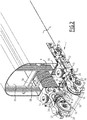
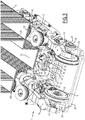
- a bogie 1 and a hinge device 2 of a railway vehicle 4 comprising at least two adjacent cars 6 are described with a view to forming a two-level railway vehicle whose interconnection allows circulation on the two levels, like this will be described later.
- the bogie 1 extends under and between two cars 6 adjacent and is arranged to support the boxes 8 of these cars. More particularly, the bogie 1 is arranged to support the ends 10, facing one another, boxes 8 of cars 6 adjacent.
- the bogie 1 comprises a frame 12 comprising two longitudinal longitudinal members 14 extending substantially in the longitudinal direction of circulation of the railway vehicle and spaced apart from each other in the transverse direction substantially perpendicular to the longitudinal direction and to the direction d elevation of the railway vehicle.
- each wheel 16 comprises an individual shaft. 18 rotatably mounted about a transverse axis on an axle box 20.
- axle box 20 By individual shaft means that each wheel 16 is rotatable relative to the chassis independently of the others, unlike a traditional bogie in which an axle generally connects the wheels in pairs and simultaneously drives two wheels in rotation.
- Each end portion of a longitudinal spar 14 rests on an axle box 20 via a primary suspension 22 allowing a vertical movement of the frame 1 relative to the wheels 16.
- the wheels are mounted so as to extend , in the transverse direction, inside the template defined by the outline of the frame 12, the axle boxes 20 being disposed on the outer side of the wheels 16.
- each spar 14 further carries at least one motor 24 arranged to drive in rotation the two wheels 16 carried by the spar.
- the motor is thus connected to the axle box 20 of each wheel 16 by transmission means.
- These transmission means are for example of the same type as those described in the document EP-1 270 359 and will not be described in more detail here.
- Each motor 24 is carried by its spar 14 between the two wheels 16 carried by said spar 14.
- the bogie 1 further comprises a braking device comprising four brake clamps 26, each arranged around a portion of one of the wheels 16 so as to brake the wheels 16 in known manner when the braking device is actuated.
- the brake clamps 26 are each disposed on the inner side of the wheels 16 in the longitudinal direction, that is to say they extend towards the center of the bogie 1 in the longitudinal direction and not outwards, as this is usually the case.
- the brake clamps 26 extend in pairs facing each other in the direction of movement so that each clamp 16 extends between the wheels of one of the pairs of wheels in the longitudinal direction. .
- the side rails 14 are connected to each other by at least one cross member 28 extending in the transverse direction between the two side members 14.
- the side members 14 are connected by two cross members. 28 spaced apart from each other in the longitudinal direction.
- the sleepers 28 comprise at least one central portion extending in a plane lowered between the longitudinal longitudinal members, that is to say in a plane extending under the plane defined by the axes of the wheels 16.
- a space 30 is delimited, in the plane of the crosspieces 28, by the two crosspieces 28 in the longitudinal direction and the longitudinal longitudinal members 14 in the transverse direction.
- the space 30 extends for example between the two motors 24 in the transverse direction.
- the bogie 1 further comprises a first abutment surface 32 and a second abutment surface 34 extending in the space 30, on either side thereof in the longitudinal direction.
- the abutment surfaces 32 and 34 thus extend one opposite the other on either side of the space 30 in the longitudinal direction, for example substantially in the center of the bogie 1 in the transverse direction.
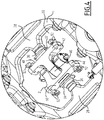
- the first and second abutment surfaces 32 and 34 are for example each carried by one of the crosspieces 28 defining the space 30, as is more particularly visible on the figure 4 .
- the first and second abutment surfaces 32 and 34 are for example formed by pads each extending in a plane defined by the transverse direction and the elevation direction.
- an absorption element, for example rubber, 36 is disposed between each abutment surface 32, 34 and the crossbar 28 which carries the abutment surface 32, 34.
- the bogie 1 further comprises secondary crossmembers 38 interconnecting the axle boxes 20, these secondary crossmembers 38 being disposed on either side of each wheel 16 at a height substantially identical to that of the crosspieces 28, that is to say a height lowered in the plane defined by the shafts 18 of the wheels 16.
- These secondary ties 38 maintain the spacing and parallelism between the wheels 16.
- the bogie above makes it possible to have a large available volume between longitudinal longitudinal members 14 above sleepers 28, as can be seen in FIGS. Figures 1 to 3 .
- the bogie 1 does not include elements arranged between the two side members 14 above the plane defined by the crosspieces 28. This volume will allow the passage of a lower interconnect floor, as will be described later .
- another bogie structure can be envisaged, apart from the space 30 and abutment surfaces 32 and 34, as long as a volume is left free for the passage of the interconnection.
- the bogie may be a driven bogie, that is to say without a motor, or all the wheels of the bogie are not necessarily rotated by a motor.
- the two boxes 8 are hinged together by the hinge device 2 fixed to the two boxes so as to form an articulated connection between the two boxes to absorb the movements between the two boxes 8.
- the hinge device 2 comprises for example a first hinge member 42 attached to the end 10 of one of the boxes 8, and a second hinge member 44 attached to the end 10 of the other box 8, the first and second articulation members 42 and 44 being connected to each other so as to form an articulated connection between the two boxes.
- the connection between the two hinge members 42 and 44 forms for example a ball joint 46 allowing a movement in all directions between the boxes.
- the hinge elements 42 and 44 are fixed to the boxes 8 so that the hinge device 2 extends in the space 30 between the abutment surfaces 32 and 34, as more particularly visible on the figure 4 .
- the hinge device 2 and the space 30 are dimensioned such that a deflection exists in the longitudinal direction. In other words, the distance separating the first abutment surface 32 from the second abutment surface 34 in the longitudinal direction is greater than the dimension of the articulation device 2 in the longitudinal direction.
- the first hinge member 42 includes an abutment surface 48 extending opposite the first abutment surface 32 and the second hinge member 44 comprises a abutment surface 50 extending opposite the second surface 34.
- the abutment surfaces also carry the fastening means 52 to the body 8.
- the bogie 1 moves until the first abutment surface 32 comes into contact with the abutment surface 48 of the first hinge member 42, so that the bogie 1 drives the moving the cars 6 through the hinge device 2 in this first longitudinal direction.
- the bogie 1 moves until the second abutment surface 34 comes into contact with the abutment surface 50 of the second articulation element 44, so that the bogie 1 causes the cars 6 to move by means of the articulation device 2 along this second direction longitudinal.
- this hinge device does not occupy either the free space between the longitudinal longitudinal members 14 above the crosspieces 28. Thus, this volume is left free for the passage of a low interconnection floor, as will now be described.
- each car 6 is a two-level car, as shown on the figure 5 .
- each car 6 comprises a lower floor 54 and an upper floor 56, arranged one above the other so as to define a lower level 58 and an upper level 60.
- the lower floor 54 and the upper floor 56 are for example substantially flat and horizontal so that cars can be crossed without difficulty.
- the lower floors 54 and 56 of a car extend at the same level as the lower floors 54 and 56 above the other level, that is to say that the lower floors 54 and 56 above all cars extend to the same height, the height of the upper floors 56 being greater than that of the lower floors 54.
- the lower floor 54 extends to a height substantially between 530 and 550 mm and the upper floor 56 extends to a height substantially between 2380 and 2400 mm. The heights given above are dependent on the template in which the vehicle must register.
- the cars 6 are connected to one another by an interconnection passage 62 extending substantially to the right of the articulation device 2 and allowing the passage of a car to another to the users of the railway vehicle.
- the interconnection passage 62 comprises a lower floor, connecting the lower floors 54 of the cars 6 and extending at the same height as these floors, and an upper floor, connecting the upper floors 56 of the cars 6 and s extending to the same height as these floors.
- the users of the railway vehicle do not need to change level to move from one car to another, as is usually the case in two-stage railway vehicles.
- the passage from one car to another by the lower level can be done without crossing a step or ramp since the lower floors all extend to the same height. Traffic in the railway vehicle is thus facilitated, in particular for people with reduced mobility.
- the layout of the lower floor of the interconnection passage 62 at the same height as that of the lower floors 54 of the cars is made possible by the arrangement of the bogie 1, which has a large free space between the longitudinal spars 14.
- the floor The lower part of the interconnection passage 62 may extend in a plane coinciding with one of the planes of the bogie 1 and more particularly with a plane close to the plane defined by the crosspieces 28, as shown in FIG. figure 4 .
- the railway vehicle described above can be implemented, as shown in the Figures 6 and 7 , with more than two cars 6 and with an optimized passenger capacity.
- the railway vehicle thus comprises five cars 6 two levels and two end cars 64, each comprising a level and a cockpit.
- the two-level cars 6 are connected to each other by an interconnection passage 62 as described above.
- Such a railway vehicle is able to accommodate 600 passengers.
- the bogie is suitable for trains traveling at high speeds of up to 200 km / h or more, while having a structure for receiving a lowered lower floor, as described above.
- the structure of the articulation device 2 could be different from that described above, as long as this articulation device is able to come into contact with the abutment surfaces of the bogie 1 so that the bogie causes the displacement. cars of the vehicle.
Landscapes
- Engineering & Computer Science (AREA)
- Mechanical Engineering (AREA)
- Transportation (AREA)
- Life Sciences & Earth Sciences (AREA)
- Chemical & Material Sciences (AREA)
- Health & Medical Sciences (AREA)
- Food Science & Technology (AREA)
- Combustion & Propulsion (AREA)
- Analytical Chemistry (AREA)
- Biochemistry (AREA)
- General Health & Medical Sciences (AREA)
- General Physics & Mathematics (AREA)
- Immunology (AREA)
- Pathology (AREA)
- Medicinal Chemistry (AREA)
- Physics & Mathematics (AREA)
- Wood Science & Technology (AREA)
- Electric Propulsion And Braking For Vehicles (AREA)
- Vehicle Cleaning, Maintenance, Repair, Refitting, And Outriggers (AREA)
- Platform Screen Doors And Railroad Systems (AREA)
- Body Structure For Vehicles (AREA)
- Braking Arrangements (AREA)
- Handcart (AREA)
Priority Applications (1)
| Application Number | Priority Date | Filing Date | Title |
|---|---|---|---|
| PL16195149T PL3159237T3 (pl) | 2015-10-23 | 2016-10-21 | Pojazd kolejowy zawierający co najmniej jeden obniżony wózek |
Applications Claiming Priority (1)
| Application Number | Priority Date | Filing Date | Title |
|---|---|---|---|
| FR1560142A FR3042768B1 (fr) | 2015-10-23 | 2015-10-23 | Vehicule ferroviaire comprenant au moins un bogie abaisse |
Publications (2)
| Publication Number | Publication Date |
|---|---|
| EP3159237A1 true EP3159237A1 (de) | 2017-04-26 |
| EP3159237B1 EP3159237B1 (de) | 2020-12-02 |
Family
ID=55072923
Family Applications (1)
| Application Number | Title | Priority Date | Filing Date |
|---|---|---|---|
| EP16195149.6A Active EP3159237B1 (de) | 2015-10-23 | 2016-10-21 | Schienenfahrzeug mit mindestens ein abgesenktes drehgestell |
Country Status (9)
| Country | Link |
|---|---|
| US (1) | US10315670B2 (de) |
| EP (1) | EP3159237B1 (de) |
| CN (1) | CN107031676B (de) |
| AU (1) | AU2016247234B2 (de) |
| ES (1) | ES2851342T3 (de) |
| FR (1) | FR3042768B1 (de) |
| IL (1) | IL248471B (de) |
| PL (1) | PL3159237T3 (de) |
| RU (1) | RU2715669C2 (de) |
Cited By (1)
| Publication number | Priority date | Publication date | Assignee | Title |
|---|---|---|---|---|
| EP3659894A1 (de) * | 2018-11-22 | 2020-06-03 | Bombardier Transportation GmbH | Fahrgestell mit einem einzelnen paar unabhängiger linker und rechter räder und seitlichen anschlagmitteln und zugehöriges niederflurschienenfahrzeug |
Families Citing this family (6)
| Publication number | Priority date | Publication date | Assignee | Title |
|---|---|---|---|---|
| FR3042769B1 (fr) * | 2015-10-23 | 2019-06-21 | Alstom Transport Technologies | Vehicule ferroviaire comprenant au moins un bogie abaisse |
| CN110104017A (zh) * | 2019-04-30 | 2019-08-09 | 中车四方车辆有限公司 | 有轨电车 |
| CN114179844A (zh) * | 2021-12-03 | 2022-03-15 | 中车唐山机车车辆有限公司 | 具有测速功能的转向架及轨道车辆 |
| CN114162164B (zh) * | 2021-12-03 | 2023-05-23 | 中车唐山机车车辆有限公司 | 一种采用铰接转向架的列车 |
| CN114179843B (zh) * | 2021-12-03 | 2023-08-22 | 中车唐山机车车辆有限公司 | 牵引装置、转向架及轨道车辆 |
| CN114194227B (zh) * | 2021-12-03 | 2023-05-23 | 中车唐山机车车辆有限公司 | 基于模块化设计的轨道车辆 |
Citations (5)
| Publication number | Priority date | Publication date | Assignee | Title |
|---|---|---|---|---|
| US3570408A (en) * | 1968-10-30 | 1971-03-16 | Gen Steel Ind Inc | Bolsterless truck having pivotally connected side frame |
| DE29512446U1 (de) * | 1995-08-02 | 1995-10-05 | Schilling, Gerhard, 52066 Aachen | Doppelstöckiger Eisenbahnwagen |
| EP0831003A2 (de) * | 1996-09-21 | 1998-03-25 | ABB Daimler-Benz Transportation (Deutschland) GmbH | Drehgestellanbindung für Jacobs-Drehgestelle |
| EP1270359A1 (de) | 2001-06-26 | 2003-01-02 | Alstom | Triebdrehgestell für ein Niederflurschienenfahrzeug |
| EP1312526A1 (de) | 2001-11-16 | 2003-05-21 | Talgo Oy | Doppelstöckige Eisenbahnwagen mit Durchgangseinrichtungen in beiden Stöcken |
Family Cites Families (8)
| Publication number | Priority date | Publication date | Assignee | Title |
|---|---|---|---|---|
| DE59307821D1 (de) * | 1993-09-10 | 1998-01-22 | Inventio Ag | Doppelstock-Gliederzug |
| FR2716149B1 (fr) * | 1994-02-15 | 1996-03-29 | Gec Alsthom Transport Sa | Articulation d'accouplement et procédé d'absorption d'énergie entre deux véhicules ferroviaires. |
| RU2180296C2 (ru) * | 1999-05-05 | 2002-03-10 | Открытое акционерное общество "Всероссийский научно-исследовательский институт транспортного машиностроения" | Автоматическая сцепка подвижного состава железнодорожного транспорта |
| CA2433974C (en) * | 2003-06-27 | 2013-08-20 | National Steel Car Limited | Symmetrical multi-unit railroad car |
| US8794160B2 (en) * | 2009-05-26 | 2014-08-05 | Kawasaki Jukogyo Kabushiki Kaisha | Low-floor railcar bogie and low-floor railcar including the same |
| ES2457591T3 (es) * | 2011-03-16 | 2014-04-28 | Bombardier Transportation Gmbh | Unidad de vehículo ferroviario con mecanismo articulado de tracción |
| CN202243514U (zh) * | 2011-08-13 | 2012-05-30 | 南车青岛四方机车车辆股份有限公司 | 高速动车组转向架 |
| CN103171563A (zh) * | 2011-12-23 | 2013-06-26 | 上海市政工程设计研究总院(集团)有限公司 | 一种轨道式快速交通运载系统及其运载方法 |
-
2015
- 2015-10-23 FR FR1560142A patent/FR3042768B1/fr not_active Expired - Fee Related
-
2016
- 2016-10-21 EP EP16195149.6A patent/EP3159237B1/de active Active
- 2016-10-21 ES ES16195149T patent/ES2851342T3/es active Active
- 2016-10-21 PL PL16195149T patent/PL3159237T3/pl unknown
- 2016-10-21 RU RU2016141484A patent/RU2715669C2/ru active
- 2016-10-24 US US15/332,111 patent/US10315670B2/en active Active
- 2016-10-24 CN CN201610940567.6A patent/CN107031676B/zh active Active
- 2016-10-24 AU AU2016247234A patent/AU2016247234B2/en active Active
- 2016-10-25 IL IL248471A patent/IL248471B/en unknown
Patent Citations (5)
| Publication number | Priority date | Publication date | Assignee | Title |
|---|---|---|---|---|
| US3570408A (en) * | 1968-10-30 | 1971-03-16 | Gen Steel Ind Inc | Bolsterless truck having pivotally connected side frame |
| DE29512446U1 (de) * | 1995-08-02 | 1995-10-05 | Schilling, Gerhard, 52066 Aachen | Doppelstöckiger Eisenbahnwagen |
| EP0831003A2 (de) * | 1996-09-21 | 1998-03-25 | ABB Daimler-Benz Transportation (Deutschland) GmbH | Drehgestellanbindung für Jacobs-Drehgestelle |
| EP1270359A1 (de) | 2001-06-26 | 2003-01-02 | Alstom | Triebdrehgestell für ein Niederflurschienenfahrzeug |
| EP1312526A1 (de) | 2001-11-16 | 2003-05-21 | Talgo Oy | Doppelstöckige Eisenbahnwagen mit Durchgangseinrichtungen in beiden Stöcken |
Cited By (3)
| Publication number | Priority date | Publication date | Assignee | Title |
|---|---|---|---|---|
| EP3659894A1 (de) * | 2018-11-22 | 2020-06-03 | Bombardier Transportation GmbH | Fahrgestell mit einem einzelnen paar unabhängiger linker und rechter räder und seitlichen anschlagmitteln und zugehöriges niederflurschienenfahrzeug |
| EP3812236A1 (de) * | 2018-11-22 | 2021-04-28 | Bombardier Transportation GmbH | Seitenpuffersystem für ein schienenfahrzeug und zugehöriges schienenfahrzeug |
| US11420658B2 (en) | 2018-11-22 | 2022-08-23 | Bombardier Transportation Gmbh | Running gear with a single pair of independent left and right wheels and lateral stop means, and associated low floor rail vehicle |
Also Published As
| Publication number | Publication date |
|---|---|
| IL248471A0 (en) | 2017-01-31 |
| RU2715669C2 (ru) | 2020-03-02 |
| FR3042768A1 (fr) | 2017-04-28 |
| AU2016247234A1 (en) | 2017-05-11 |
| AU2016247234B2 (en) | 2020-11-19 |
| US10315670B2 (en) | 2019-06-11 |
| CN107031676B (zh) | 2020-10-16 |
| PL3159237T3 (pl) | 2021-06-14 |
| EP3159237B1 (de) | 2020-12-02 |
| US20170113705A1 (en) | 2017-04-27 |
| FR3042768B1 (fr) | 2018-01-12 |
| CN107031676A (zh) | 2017-08-11 |
| ES2851342T3 (es) | 2021-09-06 |
| RU2016141484A3 (de) | 2020-01-24 |
| RU2016141484A (ru) | 2018-04-23 |
| IL248471B (en) | 2021-09-30 |
Similar Documents
| Publication | Publication Date | Title |
|---|---|---|
| EP3159237B1 (de) | Schienenfahrzeug mit mindestens ein abgesenktes drehgestell | |
| EP3034375B1 (de) | Motorisiertes drehgestell für ein schienenfahrzeug mit niederflureinstieg | |
| EP2142412B1 (de) | Drehgestell für schienenfahrzeug | |
| EP3159236B1 (de) | Schienenfahrzeug mit mindestens einem abgesenkten drehgestell umfasst | |
| EP0907546A1 (de) | Zusammengesetzte gelenkkupplung zwischen zwei wagenteilen eines nahverkersfahrzeuges, die durch ein von einer achse getragenem zwischenmodul getrennt sind | |
| EP2676859A1 (de) | Fahrgestell eines Schienenfahrzeugs mit perfektionierten Aufhängungen, insbesondere für eine Niederflur-Straßenbahn | |
| EP2782814A1 (de) | Kompaktes stadtfahrzeug | |
| EP3222483B1 (de) | Drehgestell mit aussenmotor, und entsprechendes schienenfahrzeug | |
| FR2720361A1 (fr) | Bogie pour un véhicule ferroviaire. | |
| EP3222485B1 (de) | Schienenfahrzeugdrehgestell, das eine versetzte primäre federungsvorrichtung umfasst | |
| EP3222486B1 (de) | Schienenfahrzeugdrehgestell, das ein abgesenktes fahrgestell umfasst | |
| EP3205545B1 (de) | Zweistöckiges schienenfahrzeug | |
| FR2912718A1 (fr) | Ensemble ferroviaire de transport de voyageurs, famille de tels ensembles, et procede de fabrication | |
| EP3521125A1 (de) | Fahrgestell für schienenfahrzeug | |
| FR3049252A1 (fr) | Bogie comprenant une liaison rigide entre les boites d'essieu, et vehicule ferroviaire associe | |
| EP2589523A1 (de) | Fahrgestell für Stadtbahnfahrzeug vom Typ Metro, das auf Reifen montiert ist und auf systemeigenem Fahrweg fährt | |
| EP1958845B1 (de) | Schienenfahrzeug für Reisende und entsprechender Zug für den Transport von Reisenden | |
| BE898075A (fr) | Bogie a deux essieux pour vehicules ferroviaires ou tramways et vehicules ferroviaires ou tramways utilisant ce bogie. | |
| EP2918472B1 (de) | Schienenfahrzeug, insbesondere vom typ strassenbahn, mit eingeschränkter breite | |
| CH644069A5 (fr) | Vehicule ferroviaire. | |
| EP3521129A1 (de) | Drehgestell und entsprechendes schienenfahrzeug |
Legal Events
| Date | Code | Title | Description |
|---|---|---|---|
| PUAI | Public reference made under article 153(3) epc to a published international application that has entered the european phase |
Free format text: ORIGINAL CODE: 0009012 |
|
| STAA | Information on the status of an ep patent application or granted ep patent |
Free format text: STATUS: THE APPLICATION HAS BEEN PUBLISHED |
|
| AK | Designated contracting states |
Kind code of ref document: A1 Designated state(s): AL AT BE BG CH CY CZ DE DK EE ES FI FR GB GR HR HU IE IS IT LI LT LU LV MC MK MT NL NO PL PT RO RS SE SI SK SM TR |
|
| AX | Request for extension of the european patent |
Extension state: BA ME |
|
| STAA | Information on the status of an ep patent application or granted ep patent |
Free format text: STATUS: REQUEST FOR EXAMINATION WAS MADE |
|
| 17P | Request for examination filed |
Effective date: 20170727 |
|
| RAV | Requested validation state of the european patent: fee paid |
Extension state: MA Effective date: 20170727 |
|
| RBV | Designated contracting states (corrected) |
Designated state(s): AL AT BE BG CH CY CZ DE DK EE ES FI FR GB GR HR HU IE IS IT LI LT LU LV MC MK MT NL NO PL PT RO RS SE SI SK SM TR |
|
| GRAP | Despatch of communication of intention to grant a patent |
Free format text: ORIGINAL CODE: EPIDOSNIGR1 |
|
| STAA | Information on the status of an ep patent application or granted ep patent |
Free format text: STATUS: GRANT OF PATENT IS INTENDED |
|
| INTG | Intention to grant announced |
Effective date: 20200527 |
|
| RIN1 | Information on inventor provided before grant (corrected) |
Inventor name: RODET, ALAIN Inventor name: SANCHEZ, CARLOS Inventor name: MUYO, JOSE JULIO Inventor name: LAFOIX, EMMANUEL |
|
| GRAS | Grant fee paid |
Free format text: ORIGINAL CODE: EPIDOSNIGR3 |
|
| GRAA | (expected) grant |
Free format text: ORIGINAL CODE: 0009210 |
|
| STAA | Information on the status of an ep patent application or granted ep patent |
Free format text: STATUS: THE PATENT HAS BEEN GRANTED |
|
| AK | Designated contracting states |
Kind code of ref document: B1 Designated state(s): AL AT BE BG CH CY CZ DE DK EE ES FI FR GB GR HR HU IE IS IT LI LT LU LV MC MK MT NL NO PL PT RO RS SE SI SK SM TR |
|
| REG | Reference to a national code |
Ref country code: GB Ref legal event code: FG4D Free format text: NOT ENGLISH |
|
| REG | Reference to a national code |
Ref country code: AT Ref legal event code: REF Ref document number: 1340609 Country of ref document: AT Kind code of ref document: T Effective date: 20201215 Ref country code: CH Ref legal event code: EP |
|
| REG | Reference to a national code |
Ref country code: IE Ref legal event code: FG4D Free format text: LANGUAGE OF EP DOCUMENT: FRENCH |
|
| REG | Reference to a national code |
Ref country code: DE Ref legal event code: R096 Ref document number: 602016048938 Country of ref document: DE |
|
| REG | Reference to a national code |
Ref country code: CH Ref legal event code: NV Representative=s name: DENNEMEYER AG, CH |
|
| PG25 | Lapsed in a contracting state [announced via postgrant information from national office to epo] |
Ref country code: GR Free format text: LAPSE BECAUSE OF FAILURE TO SUBMIT A TRANSLATION OF THE DESCRIPTION OR TO PAY THE FEE WITHIN THE PRESCRIBED TIME-LIMIT Effective date: 20210303 Ref country code: FI Free format text: LAPSE BECAUSE OF FAILURE TO SUBMIT A TRANSLATION OF THE DESCRIPTION OR TO PAY THE FEE WITHIN THE PRESCRIBED TIME-LIMIT Effective date: 20201202 Ref country code: NO Free format text: LAPSE BECAUSE OF FAILURE TO SUBMIT A TRANSLATION OF THE DESCRIPTION OR TO PAY THE FEE WITHIN THE PRESCRIBED TIME-LIMIT Effective date: 20210302 Ref country code: RS Free format text: LAPSE BECAUSE OF FAILURE TO SUBMIT A TRANSLATION OF THE DESCRIPTION OR TO PAY THE FEE WITHIN THE PRESCRIBED TIME-LIMIT Effective date: 20201202 |
|
| REG | Reference to a national code |
Ref country code: NL Ref legal event code: MP Effective date: 20201202 |
|
| REG | Reference to a national code |
Ref country code: AT Ref legal event code: MK05 Ref document number: 1340609 Country of ref document: AT Kind code of ref document: T Effective date: 20201202 |
|
| PG25 | Lapsed in a contracting state [announced via postgrant information from national office to epo] |
Ref country code: SE Free format text: LAPSE BECAUSE OF FAILURE TO SUBMIT A TRANSLATION OF THE DESCRIPTION OR TO PAY THE FEE WITHIN THE PRESCRIBED TIME-LIMIT Effective date: 20201202 Ref country code: BG Free format text: LAPSE BECAUSE OF FAILURE TO SUBMIT A TRANSLATION OF THE DESCRIPTION OR TO PAY THE FEE WITHIN THE PRESCRIBED TIME-LIMIT Effective date: 20210302 Ref country code: LV Free format text: LAPSE BECAUSE OF FAILURE TO SUBMIT A TRANSLATION OF THE DESCRIPTION OR TO PAY THE FEE WITHIN THE PRESCRIBED TIME-LIMIT Effective date: 20201202 |
|
| PG25 | Lapsed in a contracting state [announced via postgrant information from national office to epo] |
Ref country code: NL Free format text: LAPSE BECAUSE OF FAILURE TO SUBMIT A TRANSLATION OF THE DESCRIPTION OR TO PAY THE FEE WITHIN THE PRESCRIBED TIME-LIMIT Effective date: 20201202 Ref country code: HR Free format text: LAPSE BECAUSE OF FAILURE TO SUBMIT A TRANSLATION OF THE DESCRIPTION OR TO PAY THE FEE WITHIN THE PRESCRIBED TIME-LIMIT Effective date: 20201202 |
|
| REG | Reference to a national code |
Ref country code: LT Ref legal event code: MG9D |
|
| PG25 | Lapsed in a contracting state [announced via postgrant information from national office to epo] |
Ref country code: CZ Free format text: LAPSE BECAUSE OF FAILURE TO SUBMIT A TRANSLATION OF THE DESCRIPTION OR TO PAY THE FEE WITHIN THE PRESCRIBED TIME-LIMIT Effective date: 20201202 Ref country code: EE Free format text: LAPSE BECAUSE OF FAILURE TO SUBMIT A TRANSLATION OF THE DESCRIPTION OR TO PAY THE FEE WITHIN THE PRESCRIBED TIME-LIMIT Effective date: 20201202 Ref country code: LT Free format text: LAPSE BECAUSE OF FAILURE TO SUBMIT A TRANSLATION OF THE DESCRIPTION OR TO PAY THE FEE WITHIN THE PRESCRIBED TIME-LIMIT Effective date: 20201202 Ref country code: SM Free format text: LAPSE BECAUSE OF FAILURE TO SUBMIT A TRANSLATION OF THE DESCRIPTION OR TO PAY THE FEE WITHIN THE PRESCRIBED TIME-LIMIT Effective date: 20201202 Ref country code: RO Free format text: LAPSE BECAUSE OF FAILURE TO SUBMIT A TRANSLATION OF THE DESCRIPTION OR TO PAY THE FEE WITHIN THE PRESCRIBED TIME-LIMIT Effective date: 20201202 Ref country code: PT Free format text: LAPSE BECAUSE OF FAILURE TO SUBMIT A TRANSLATION OF THE DESCRIPTION OR TO PAY THE FEE WITHIN THE PRESCRIBED TIME-LIMIT Effective date: 20210405 Ref country code: SK Free format text: LAPSE BECAUSE OF FAILURE TO SUBMIT A TRANSLATION OF THE DESCRIPTION OR TO PAY THE FEE WITHIN THE PRESCRIBED TIME-LIMIT Effective date: 20201202 |
|
| PG25 | Lapsed in a contracting state [announced via postgrant information from national office to epo] |
Ref country code: AT Free format text: LAPSE BECAUSE OF FAILURE TO SUBMIT A TRANSLATION OF THE DESCRIPTION OR TO PAY THE FEE WITHIN THE PRESCRIBED TIME-LIMIT Effective date: 20201202 |
|
| REG | Reference to a national code |
Ref country code: DE Ref legal event code: R097 Ref document number: 602016048938 Country of ref document: DE |
|
| REG | Reference to a national code |
Ref country code: ES Ref legal event code: FG2A Ref document number: 2851342 Country of ref document: ES Kind code of ref document: T3 Effective date: 20210906 |
|
| PG25 | Lapsed in a contracting state [announced via postgrant information from national office to epo] |
Ref country code: IS Free format text: LAPSE BECAUSE OF FAILURE TO SUBMIT A TRANSLATION OF THE DESCRIPTION OR TO PAY THE FEE WITHIN THE PRESCRIBED TIME-LIMIT Effective date: 20210402 |
|
| PLBE | No opposition filed within time limit |
Free format text: ORIGINAL CODE: 0009261 |
|
| STAA | Information on the status of an ep patent application or granted ep patent |
Free format text: STATUS: NO OPPOSITION FILED WITHIN TIME LIMIT |
|
| PG25 | Lapsed in a contracting state [announced via postgrant information from national office to epo] |
Ref country code: AL Free format text: LAPSE BECAUSE OF FAILURE TO SUBMIT A TRANSLATION OF THE DESCRIPTION OR TO PAY THE FEE WITHIN THE PRESCRIBED TIME-LIMIT Effective date: 20201202 |
|
| 26N | No opposition filed |
Effective date: 20210903 |
|
| PG25 | Lapsed in a contracting state [announced via postgrant information from national office to epo] |
Ref country code: DK Free format text: LAPSE BECAUSE OF FAILURE TO SUBMIT A TRANSLATION OF THE DESCRIPTION OR TO PAY THE FEE WITHIN THE PRESCRIBED TIME-LIMIT Effective date: 20201202 Ref country code: SI Free format text: LAPSE BECAUSE OF FAILURE TO SUBMIT A TRANSLATION OF THE DESCRIPTION OR TO PAY THE FEE WITHIN THE PRESCRIBED TIME-LIMIT Effective date: 20201202 |
|
| PG25 | Lapsed in a contracting state [announced via postgrant information from national office to epo] |
Ref country code: IS Free format text: LAPSE BECAUSE OF FAILURE TO SUBMIT A TRANSLATION OF THE DESCRIPTION OR TO PAY THE FEE WITHIN THE PRESCRIBED TIME-LIMIT Effective date: 20210402 |
|
| REG | Reference to a national code |
Ref country code: BE Ref legal event code: MM Effective date: 20211031 |
|
| GBPC | Gb: european patent ceased through non-payment of renewal fee |
Effective date: 20211021 |
|
| PG25 | Lapsed in a contracting state [announced via postgrant information from national office to epo] |
Ref country code: MC Free format text: LAPSE BECAUSE OF FAILURE TO SUBMIT A TRANSLATION OF THE DESCRIPTION OR TO PAY THE FEE WITHIN THE PRESCRIBED TIME-LIMIT Effective date: 20201202 |
|
| PG25 | Lapsed in a contracting state [announced via postgrant information from national office to epo] |
Ref country code: LU Free format text: LAPSE BECAUSE OF NON-PAYMENT OF DUE FEES Effective date: 20211021 Ref country code: GB Free format text: LAPSE BECAUSE OF NON-PAYMENT OF DUE FEES Effective date: 20211021 Ref country code: BE Free format text: LAPSE BECAUSE OF NON-PAYMENT OF DUE FEES Effective date: 20211031 |
|
| PG25 | Lapsed in a contracting state [announced via postgrant information from national office to epo] |
Ref country code: IE Free format text: LAPSE BECAUSE OF NON-PAYMENT OF DUE FEES Effective date: 20211021 |
|
| PG25 | Lapsed in a contracting state [announced via postgrant information from national office to epo] |
Ref country code: HU Free format text: LAPSE BECAUSE OF FAILURE TO SUBMIT A TRANSLATION OF THE DESCRIPTION OR TO PAY THE FEE WITHIN THE PRESCRIBED TIME-LIMIT; INVALID AB INITIO Effective date: 20161021 |
|
| PG25 | Lapsed in a contracting state [announced via postgrant information from national office to epo] |
Ref country code: CY Free format text: LAPSE BECAUSE OF FAILURE TO SUBMIT A TRANSLATION OF THE DESCRIPTION OR TO PAY THE FEE WITHIN THE PRESCRIBED TIME-LIMIT Effective date: 20201202 |
|
| P01 | Opt-out of the competence of the unified patent court (upc) registered |
Effective date: 20230823 |
|
| PG25 | Lapsed in a contracting state [announced via postgrant information from national office to epo] |
Ref country code: MK Free format text: LAPSE BECAUSE OF FAILURE TO SUBMIT A TRANSLATION OF THE DESCRIPTION OR TO PAY THE FEE WITHIN THE PRESCRIBED TIME-LIMIT Effective date: 20201202 |
|
| VS25 | Lapsed in a validation state [announced via postgrant information from nat. office to epo] |
Ref country code: MA Free format text: LAPSE BECAUSE OF FAILURE TO SUBMIT A TRANSLATION OF THE DESCRIPTION OR TO PAY THE FEE WITHIN THE PRESCRIBED TIME-LIMIT Effective date: 20201202 |
|
| PG25 | Lapsed in a contracting state [announced via postgrant information from national office to epo] |
Ref country code: TR Free format text: LAPSE BECAUSE OF FAILURE TO SUBMIT A TRANSLATION OF THE DESCRIPTION OR TO PAY THE FEE WITHIN THE PRESCRIBED TIME-LIMIT Effective date: 20201202 |
|
| PG25 | Lapsed in a contracting state [announced via postgrant information from national office to epo] |
Ref country code: MT Free format text: LAPSE BECAUSE OF FAILURE TO SUBMIT A TRANSLATION OF THE DESCRIPTION OR TO PAY THE FEE WITHIN THE PRESCRIBED TIME-LIMIT Effective date: 20201202 |
|
| REG | Reference to a national code |
Ref country code: ES Ref legal event code: PC2A Owner name: ALSTOM HOLDINGS Effective date: 20250310 |
|
| REG | Reference to a national code |
Ref country code: CH Ref legal event code: U11 Free format text: ST27 STATUS EVENT CODE: U-0-0-U10-U11 (AS PROVIDED BY THE NATIONAL OFFICE) Effective date: 20251101 |
|
| PGFP | Annual fee paid to national office [announced via postgrant information from national office to epo] |
Ref country code: DE Payment date: 20251021 Year of fee payment: 10 |
|
| PGFP | Annual fee paid to national office [announced via postgrant information from national office to epo] |
Ref country code: IT Payment date: 20251024 Year of fee payment: 10 |
|
| PGFP | Annual fee paid to national office [announced via postgrant information from national office to epo] |
Ref country code: FR Payment date: 20251030 Year of fee payment: 10 |
|
| PGFP | Annual fee paid to national office [announced via postgrant information from national office to epo] |
Ref country code: CH Payment date: 20251101 Year of fee payment: 10 |
|
| PGFP | Annual fee paid to national office [announced via postgrant information from national office to epo] |
Ref country code: PL Payment date: 20251009 Year of fee payment: 10 |
|
| PGFP | Annual fee paid to national office [announced via postgrant information from national office to epo] |
Ref country code: ES Payment date: 20251210 Year of fee payment: 10 |