EP3159461B1 - Kantenschutzsystem - Google Patents
Kantenschutzsystem Download PDFInfo
- Publication number
- EP3159461B1 EP3159461B1 EP16197556.0A EP16197556A EP3159461B1 EP 3159461 B1 EP3159461 B1 EP 3159461B1 EP 16197556 A EP16197556 A EP 16197556A EP 3159461 B1 EP3159461 B1 EP 3159461B1
- Authority
- EP
- European Patent Office
- Prior art keywords
- barrier
- protection system
- edge protection
- uprights
- upright
- Prior art date
- Legal status (The legal status is an assumption and is not a legal conclusion. Google has not performed a legal analysis and makes no representation as to the accuracy of the status listed.)
- Active
Links
Images









Classifications
-
- E—FIXED CONSTRUCTIONS
- E04—BUILDING
- E04G—SCAFFOLDING; FORMS; SHUTTERING; BUILDING IMPLEMENTS OR AIDS, OR THEIR USE; HANDLING BUILDING MATERIALS ON THE SITE; REPAIRING, BREAKING-UP OR OTHER WORK ON EXISTING BUILDINGS
- E04G21/00—Preparing, conveying, or working-up building materials or building elements in situ; Other devices or measures for constructional work
- E04G21/32—Safety or protective measures for persons during the construction of buildings
- E04G21/3204—Safety or protective measures for persons during the construction of buildings against falling down
- E04G21/3223—Means supported by building floors or flat roofs, e.g. safety railings
-
- E—FIXED CONSTRUCTIONS
- E04—BUILDING
- E04G—SCAFFOLDING; FORMS; SHUTTERING; BUILDING IMPLEMENTS OR AIDS, OR THEIR USE; HANDLING BUILDING MATERIALS ON THE SITE; REPAIRING, BREAKING-UP OR OTHER WORK ON EXISTING BUILDINGS
- E04G5/00—Component parts or accessories for scaffolds
- E04G5/004—Storage and transport racks for scaffolding components
-
- E—FIXED CONSTRUCTIONS
- E04—BUILDING
- E04G—SCAFFOLDING; FORMS; SHUTTERING; BUILDING IMPLEMENTS OR AIDS, OR THEIR USE; HANDLING BUILDING MATERIALS ON THE SITE; REPAIRING, BREAKING-UP OR OTHER WORK ON EXISTING BUILDINGS
- E04G5/00—Component parts or accessories for scaffolds
- E04G5/14—Railings
-
- E—FIXED CONSTRUCTIONS
- E04—BUILDING
- E04G—SCAFFOLDING; FORMS; SHUTTERING; BUILDING IMPLEMENTS OR AIDS, OR THEIR USE; HANDLING BUILDING MATERIALS ON THE SITE; REPAIRING, BREAKING-UP OR OTHER WORK ON EXISTING BUILDINGS
- E04G5/00—Component parts or accessories for scaffolds
- E04G5/14—Railings
- E04G5/142—Railings extensible or telescopic
-
- E—FIXED CONSTRUCTIONS
- E04—BUILDING
- E04G—SCAFFOLDING; FORMS; SHUTTERING; BUILDING IMPLEMENTS OR AIDS, OR THEIR USE; HANDLING BUILDING MATERIALS ON THE SITE; REPAIRING, BREAKING-UP OR OTHER WORK ON EXISTING BUILDINGS
- E04G7/00—Connections between parts of the scaffold
- E04G7/02—Connections between parts of the scaffold with separate coupling elements
- E04G7/06—Stiff scaffolding clamps for connecting scaffold members of common shape
- E04G7/08—Clamps for parallelly-arranged members
- E04G7/10—Self-tightening clamps, e.g. stirrups
-
- E—FIXED CONSTRUCTIONS
- E04—BUILDING
- E04G—SCAFFOLDING; FORMS; SHUTTERING; BUILDING IMPLEMENTS OR AIDS, OR THEIR USE; HANDLING BUILDING MATERIALS ON THE SITE; REPAIRING, BREAKING-UP OR OTHER WORK ON EXISTING BUILDINGS
- E04G5/00—Component parts or accessories for scaffolds
- E04G5/14—Railings
- E04G2005/148—Railings latticed or netted
Definitions
- This invention relates to an edge protection system. Particularly, but not exclusively, the invention relates to an edge protection system for use as a temporary guard rail for a scaffolding system.
- Known scaffolding systems are generally of two kinds; those comprising customised proprietary components and those comprising a selection of standard tubes and fittings.
- the first kind typically requires skilled construction and has parts configured to clip together in a specific arrangement, which brings attendant design constraints.
- the first kind is usually so customised to suit a particular application that it is not suitable for re-use and is generally scrapped once the project is complete.
- the second kind is generally considered more versatile but is labour intensive as it requires parts to be clamped or welded together. Also, at the end of the use of a particular construction the welded parts are generally severed by hot works and this can be dangerous as well as time-consuming.
- a scaffolding system will comprise vertical members (also known as standards) to which are connected two sets of horizontal bars: ledger bars extending in use alongside the structure being built or maintained and transom bars extending towards, typically transverse to, the structure.
- ledger bars extending in use alongside the structure being built or maintained
- transom bars extending towards, typically transverse to, the structure.
- the scaffold construction erected from the scaffolding system will also normally comprise diagonal brace bars to provide rigidity to the scaffold construction.
- a temporary barrier (often referred to as an edge protection system) needs to be fixed to prevent workers from falling from the scaffold construction while working on the adjacent structure.
- This barrier typically comprises a steel mesh panel attached to upright posts.
- the resulting barrier restricts access to the building structure beyond the mesh; such access is often required for tasks such as casting concrete slabs and installing cladding or glazing panels.
- individual mesh panels are often removed to provide the required access and this leads to an increased risk of a worker falling from the scaffolding structure.
- workers are often secured to the scaffolding by a lanyard to an anchor point on one side of the section from which the barrier has been removed.
- this can impede the ability of the worker to perform the task efficiently.
- the barrier is typically set at a minimum height to allow some degree of access and then adjusted to a new height once the slab is cast. However, this is not ideal as the barrier is not set at the required height relative to the structure throughout the process.
- the area in which that worker is performing the task will need to be zoned off to prevent others from entering the area from which the barrier has been removed. This will also prevent access to other areas of the scaffold construction beyond that section where the barrier has been removed, thereby reducing the speed at which completion of the building structure can be effected.
- edge protection systems are known from the documents DE20107666 U1 , WO2008086557 , US6038829 and DE20001948 U1 .
- an edge protection system as defined in claim1.
- a method of assembling an edge protection system for a working platform comprising providing a fixing means on a base, releasably engaging a barrier with the fixing means and raising the base, with the barrier retained thereon, to a working position, the base defining a working platform.
- the present invention enables the attachment of a barrier to a base before the base is raised into position. Accordingly, the risk associated with working at height without a barrier (during either the erection of a scaffolding construction or the installation of a barrier) is eliminated. Furthermore, only a few individual components are required to be assembled when erecting the edge protection system and consequently construction of the edge protection system is quick, straightforward and requires minimal skill. In addition, disassembly of the edge protection system is also relatively quick and easy to perform since the barrier is releasably attached to the base. Thus, the danger associated with using hot works to remove the barrier is also eliminated. Moreover, embodiments of the invention do not require any tools to install or remove the barrier from the fixing means - manual manipulation being all that is required.
- a further advantage of the present invention is that the individual components may be re-used immediately, without requiring any maintenance or repair. Furthermore, aspects of the present invention provide for a sustainable system, the components of which can be re-used in a variety of ways to suit a number of different applications.
- a beam, a slab, a panel or any pre-manufactured floor element may constitute the base.
- the beam may be made from steel and the slab may be made from concrete.
- the step of providing a fixing means on a base may comprise securing a fixing means to a base or providing a fixing means that is integral with a base.
- the fixing means may be releasably secured to the base.
- the fixing means may be welded to the base.
- the fixing means comprises a socket or a plug configured for engagement with a part of the barrier that constitutes a complementary plug or socket.
- the fixing means may be constituted by a recess in the base, which forms a socket for receiving a part of the barrier that forms a complementary plug.
- the socket may be in the form of a cylindrical tube and the plug may be in the form of a cylindrical rod.
- An intermediate element may be provided between the fixing means and barrier to aid the engagement therebetween.
- the intermediate element is a sleeve and may be formed from a plastics material.
- the barrier may comprise at least one opening configured to allow access therethrough, the at least one opening being configured to enable a worker to work beyond the barrier whilst the barrier remains in place. It will be understood that such a structure may allow a large concrete slab to be cast without the need to adjust the edge protection system. In addition, tasks such as cladding and glazing can be performed without compromising safety.
- the barrier may be provided in any convenient size (for example, in 1m or 2m widths, having a height of between 1m and 1.5m).
- the barrier comprises at least two horizontally spaced apart uprights with an upper and a lower horizontal element spanning therebetween.
- the lower horizontal element is preferably spaced from the base.
- At least one intermediate horizontal element may be provided between the upper and lower horizontal elements.
- the uprights may be of substantially similar height and a lower end of each upright may constitute a plug or socket for engagement in a complementary socket or plug of two respective fixing means.
- At least one additional barrier and respective fixing means may be provided.
- Coupling means may be provided to couple the barriers together.
- the coupling means may be releasable and may comprise a clamp, clip, clasp or strap.
- the coupling means may be configured for a snap-fit engagement with an adjacent barrier.
- the coupling means may be spring-loaded and may be configured such that in its rest position it can grip an adjacent barrier and in its tensioned position it can be released from said barrier.
- the coupling means may be provided on one end of a barrier for coupling to the closest end of an adjacent barrier so that the barriers are coupled end to end.
- the at least one additional barrier may comprise at least two horizontally spaced apart uprights with an upper and a lower horizontal element spanning therebetween.
- the lower horizontal element is preferably spaced from the base.
- At least one intermediate horizontal element may be provided between the upper and lower horizontal elements.
- a lower end of at least one of the uprights may extend lower than the lower horizontal element and may constitute a plug or socket for engagement in a complementary socket or plug of the fixing means.
- At least one of the other uprights may extend no lower than the lower horizontal element.
- the coupling means may be provided on the at least one of said other uprights.
- a coupler may be provided to allow an additional barrier to be coupled to an adjacent barrier with a degree of overlap therebetween; the coupler being attachable to the barrier at any point along the length of the barrier and wherein the coupler is configured to secure the at least one additional barrier to said barrier. Accordingly, the coupler allows for an edge protection system of any size (greater than the size of one barrier) to be constructed and therefore allows for any length of base to be protected.
- the coupler may comprise a post having a first series of coupling means configured for attaching the post to the barrier.
- a second series of coupling means configured for attaching the additional barrier to the post may either be provided on the additional barrier or on the post.
- the post may be configured for attachment between at least two of the upper, lower or intermediate horizontal elements of a barrier.
- the coupling means of the additional barrier may constitute the second series of coupling means for attaching the additional barrier to the post, as opposed to the closest end of an adjacent barrier.
- the barrier comprises at least one upright coupled to a laterally extending body, the at least one upright being laterally moveable along the length of the body.
- the lower end of the at least one upright constitutes a plug or socket for engagement in a complementary socket or plug of the fixing means.
- a locking means is provided to fix the position of the at least one upright with respect to the body.
- the body comprises an upper and a lower horizontal element.
- An intermediate horizontal element may be provided therebetween.
- a vertical support post is provided between the upper and lower horizontal elements to provide a more rigid structure and to minimise the deflection of the upper and lower horizontal elements.
- the barriers may be of any shape or size (for example, planar or curved, rectangular or square).
- an edge protection system can be constructed to suit any shape of scaffolding or building structure.
- the barriers comprise attachment means for attaching a mesh panel.
- the mesh panel can provide increased containment but can be selectively removed to provide local (but safe) access through a barrier.
- the attachment means are constituted by at least one carabiner.
- the attachment means are pivotally mounted on the barrier.
- a supplementary mesh panel may be provided for extending the height of said mesh panel so as to provide even greater containment when required.
- the supplementary mesh panel may include an anti-roll device to prevent the supplementary mesh panel from rotating about a horizontal axis when in use.
- a guard rail comprising a barrier, at least one additional barrier and a coupler; the coupler being attachable to the barrier at any point along the length of the barrier and wherein the coupler is configured to secure the at least one additional barrier to said barrier.
- the coupler in use, is attached to an intermediate point on the barrier, as required, and the additional barrier is then secured to the coupler so as to couple the barrier and the additional barrier together in an overlapping configuration.
- the third aspect of the present invention enables a guard rail of any size (greater than the size of one barrier) to be constructed.
- the barrier, the at least one additional barrier and the coupler may comprise any of the features described above in relation to the edge protection system.
- a barrier comprising at least one upright coupled to a laterally extending body, the at least one upright being laterally moveable along the length of the body.
- the barrier according to the fourth aspect of the invention may comprise any of the features described above in relation to the edge protection system and in particular, in relation to the barrier described in the second embodiment.
- an advantage of such a barrier is that the position of the supporting upright can be varied to provide the desired body width at either side of the upright.
- the barrier can be mounted with its upright close to another structure by simply moving the upright towards one end of the body.
- This is particularly useful when erecting a barrier to fill a gap of fixed length (e.g. along a beam) since the gap may not be filled by a whole number of barriers erected end to end.
- one of the barriers (usually an end barrier) can be configured such that a part of the body of one barrier overlaps (i.e. lies adjacent to) a part of the body of another barrier and the degree of overlap can be selected by varying the position of the upright with respect to the body.
- the moveable nature of the upright can allow for better alignment with pre-fitted fixing means such as sockets welded to a base if said sockets are not positioned accurately (e.g. if they are not welded exactly 1m apart).
- a further advantage of the barrier according to the fourth aspect of the invention is that only one type of barrier is required (regardless of the length of gap to protect) since the configuration of each can be independently adjusted as required, for example to provide the required degree of overlap. Also, as each barrier is of the same type they can be easily stacked and transported.
- a barrier comprising a framework of spaced vertical and horizontal members through which workers can safely reach beyond the barrier to the building structure.
- increased containment can be achieved by attaching a mesh panel to the barrier to block access there-through.
- the attachment can be achieved by having a series of carabiners rotatably mounted on the barrier and arranged such that they can grip onto a transverse member of a mesh panel to hold the panel adjacent the barrier.
- edge protection system In the case of casting concrete slabs, it is important that the edge protection system can be arranged to provide adequate protection both before and after the slab has been cast.
- Current ways to achieve this include using plastic tie wraps or another form of coupler to suspend the barrier at the desired height before and after the slab has been cast.
- plastic tie wraps or another form of coupler to suspend the barrier at the desired height before and after the slab has been cast.
- traditional tie wraps and couplers are discrete items which are easily misplaced and may not be available when required. Furthermore they are awkward to use, especially when attempting to hold the barrier whilst fixing them in place. Moreover, additional tools are often required when employing such a coupler.
- a carabiner such as that described above, can address some of the difficulties, its fixed position with respect to the barrier limits its use in adjusting the height of the edge protection system.
- an adjustment device for an edge protection system comprising a base unit with an attachment means for an edge protection element coupled thereto, the attachment means being movable along the base unit.
- the attachment means may be configured for coupling a support means and a containment means together to form an edge protection system.
- an edge protection system comprising a support means, a containment means and an adjustment device in accordance with the fifth aspect of the invention on one of the support means or the containment means.
- a method of assembling an edge protection system comprising providing a support means, a containment means and an adjustment device in accordance with the fifth aspect of the invention on one of the support means or the containment means; placing the attachment means in a desired position with respect to the support means and/or containment means; and coupling the support means and containment means together via the attachment means.
- the last three aspects described above enable the attachment of a containment means (e.g. mesh panel) to a support means (e.g. a post or frame barrier) in a number of different relative positions. Consequently, the present invention can be used to adjust the height of one component (e.g. the mesh panel) relative to the other (e.g. the barrier). Accordingly, the height of an edge protection system can be quickly and easily adjusted, say, to compensate for the height of a concrete slab once cast.
- a containment means e.g. mesh panel
- a support means e.g. a post or frame barrier
- attachment means is coupled to a base unit which can be permanently mounted on one of a support means or containment means results in the attachment means always being available for use and means that there is no need to fix the attachment means to both parts during use. This simplifies the task of coupling the support means and containment means together, which therefore reduces the time and effort spent on this task.
- embodiments of the invention do not require the use of tools to couple or decouple the components together - manual manipulation of the attachment means being all that is required.
- the base unit may be configured for fixing to a support means or a containment means or it may form an integral part of a support means or a containment means. It will be understood that having an integral base unit helps to reduce the overall weight of the edge protection system and makes the system easier and cheaper to produce and assemble.
- the support means may be constituted by a support post or barrier.
- the containment means may be constituted by a mesh panel.
- the base unit may comprise marking to indicate where the attachment means should be positioned for a particular use. For example, when casting a slab of a particular height (e.g. 250mm) the base unit may indicate where to position the attachment means so that once a mesh panel is attached to the attachment means it is provided to the required height above the slab.
- marking to indicate where the attachment means should be positioned for a particular use. For example, when casting a slab of a particular height (e.g. 250mm) the base unit may indicate where to position the attachment means so that once a mesh panel is attached to the attachment means it is provided to the required height above the slab.
- the attachment means may comprise a carabiner, a hook or a clasp.
- the attachment means may be rotatably or pivotally coupled to the base unit.
- the base unit may be configured such that the attachment means is moveable in a substantially vertical and/or horizontal direction, when in use.
- the base unit may include a slot along which the attachment means can slide. Both ends of the slot may be closed to retain the attachment means therein. In one embodiment, one end of the slot may be selectively opened to allow the attachment means to be removed and/or replaced.
- a locking means may be provided to lock the attachment means in a desired position with respect to the base unit, when in use.
- the locking means may be configured such that in one orientation the attachment means is moveable along the base unit and in another orientation the attachment means is locked in a fixed position along the base unit.
- the locking means and attachment means may be held in a fixed relative position such that the movement of one results in corresponding movement of the other.
- the locking means may form an integral part of the attachment means.
- the base unit includes a profiled slot and the locking means comprises a bolt having a semi-circular cut-out at one side thereof such that in one orientation the bolt is permitted to travel along the profiled slot and in another orientation the bolt is held in a fixed position in the profiled slot.
- the profiled slot may be generally longitudinal and include a plurality of semi-circular cut-outs along one side thereof.
- the attachment means may be configured such that the locking means is orientated into its locked position under the influence of gravity.
- the attachment means can be moved by a user acting against gravity, for example by rotating the attachment means to a horizontal rather than a vertical orientation so as to unlock the locking means.
- the attachment means can then be slid along the base unit to a desired position and thereafter rotated back to a locked (e.g. vertical) position for subsequent attachment to a support/containment means.
- the fact that the attachment means rotates to a substantially vertical position under gravity can help to hold the containment means close to the support means so as to minimise any rattling between these two components when it is windy, for example.
- the base unit may be constituted by a U-shaped channel configured to be bolted or welded onto a support post.
- FIG. 1 to 5 there is illustrated part of an edge protection system 10 in accordance with a first embodiment not part of the present invention.
- the part of the edge protection system 10 shown in these Figures comprises a fixing means in the form of a tubular steel socket 12 and an intermediate element constituted by a tubular plastic sleeve 14 which is approximately twice as long as the socket 12.
- the sleeve 14 is sized to fit snugly within the socket 12 to provide a hollow channel 16 therethrough.
- the socket 12 Prior to insertion of the sleeve 14, the socket 12 is welded in an upright position to a base 18.
- the base 18 is a horizontal steel I-beam 20 for use in forming an edge of a working platform in a scaffolding construction.
- the I-beam 20 is located between two vertical I-beam supports 22, also made from steel.
- the I-beam 20 is shown at a position approximately one third of the way up the supports 22, it will be understood that when the edge protection system 10 is being assembled on the I-beam 20 it is being assembled at a height which can be easily reached from the ground.
- the first socket 12 is provided at a first end 24 of the I-beam 20, adjacent the first support 22.
- the second socket 12 is provided a pre-determined distance 'D' along the I-beam 20 from the first socket 12 - the distance 'D' being governed by the length of each barrier, as will be described later.
- the third socket 12 is then provided at the same distance 'D' from the second socket 12.
- the fourth socket 12 is provided at a second end 26 of the I-beam 20, adjacent the second support 22. Note that the distance between the third and fourth sockets 12 is less than the distance 'D'.
- each socket 12 may be indicated along the length of the I-beam 20.
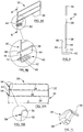
- Figure 6 shows a first barrier 30 for use with the part of the edge protection system 10 shown in Figure 1 .
- the first barrier 30 comprises two horizontally spaced apart vertical uprights 32 of substantially similar height. The upper ends 33 of the uprights 32 curve inwardly and connect via an upper horizontal bar 34. Approximately a third of the distance up from the lower ends 35 of the uprights 32, a lower horizontal bar 36 spans between the uprights 32. Midway between the upper and lower horizontal bars 34, 36, an intermediate bar 38 is provided between the two uprights 32.
- the first barrier 30 is constructed from hollow metal tubing.
- the lower end 35 of each upright 32 constitutes, in use, a plug for a respective socket 12 and sleeve 14, as illustrated in Figures 7A and 7B .
- the lower ends 35 of the first barrier 30 are located into the respective first and second sockets 12.
- the sleeves 14 are ensure a snug fit between the lower ends 35 and the sockets 12, whilst also facilitating easier insertion and removal of the first barrier 30 from the sockets 12.
- the sockets 12 may be secured to an alternative base 40.
- the base 40 comprises a corrugated horizontal panel 42 and an upright planar guard rail 44.
- the guard rail extends vertically upwardly from one side of the panel 42 and includes an in-turned lip 46 along its top edge.
- the guard rail 44 terminates below the lower horizontal bar 36 of the first barrier 30 and the socket 12 is welded to the panel 42 between adjacent corrugations 48.
- Figures 10A and 10B show a (second) additional barrier 50 for use with the part of the edge protection system 10 shown in Figures 1 and 7A .
- the construction of the additional barrier 50 is similar to that of the first barrier 30 and so like numerals will be used where appropriate.
- the main difference between the first barrier 30 and the additional barrier 50 is that the additional barrier only has one upright 32 having a lower end 35 configured for engagement in a socket 12.
- a connecting upright 52 is provided in place of another upright 32.
- the connecting upright 52 is similar to the upright 32 but only extends between the upper horizontal bar 34 and the lower horizontal bar 36 (i.e. is doe not include a lower end 35 configured for engagement in a socket 12).
- clasps 54 are provided on the connecting upright 52.
- One of the clasps 54 is provided close to the upper horizontal bar 34 while the other of the clasps 54 is provided close to the lower horizontal bar 36.
- the clasps 54 are provided to couple the additional barrier 50 to the first barrier 30, as will be described below.
- the length of the additional barrier 50 is slightly less than that of the first barrier 30. Whilst the distance between the uprights 32 of the first barrier 30 corresponds to the distance 'D' between the sockets 12, as shown in Figure 7A , the distance between the upright 32 and connecting upright 52 of the additional barrier 50 is less than 'D', as indicated in Figure 10A .
- the distance between the upright 32 and the clasps 54 of the additional barrier 50 corresponds to the distance 'D'. This allows for the clasps 54 to be attached to one of the uprights 32 of the first barrier 30 when it is located in a respective socket 12 and the upright 32 of the additional barrier 50 is located in the next adjacent socket 12, as will be described more fully below.
- FIG 11 shows an enlarged view of one of the clasps 54.
- the clasp 54 includes a concave arm 56 configured to wrap part-way around the upright 32 of the first barrier 30 once snap-fitted thereto.
- the clasp 54 also includes a spring-loaded part 58 at one end of the concave arm 56.
- the spring-loaded part 58 is configured such that in its rest position it extends part-way around the upright 32 so as to grip onto it.
- the spring-loaded part 58 can be manually moved away from the upright 32 by applying pressure against the spring bias.
- the clasps 54 serve to couple the end of the additional barrier 50 to the end of the first barrier 30.
- the clasps 54 may also be employed to couple one additional barrier 50 to another additional barrier 50. It should be noted that no additional tools are required to operate the clasps 54 and so the barriers 30, 50 can be coupled together (and uncoupled) via manual manipulation alone.
- FIGs 12A , B and C illustrate the attachment of an additional barrier 50 to the edge protection system 10 of Figure 7A , once the first barrier 30 has been positioned.
- the additional barrier 50 is viewed from the opposite side to that in Figures 10A and B .
- the upright 32 of the additional barrier 50 is located in the socket 12 and sleeve 14 closest to the free end of the first barrier 30.
- the additional barrier 50 is then rotated about this pivot point to bring the connecting upright 52 adjacent to the free upright 32 of the first barrier 30 whereupon pushing the additional barrier 50 into line with the first barrier 30 forces the clasps 54 (located on the connecting upright 52) to click into engagement with the upright 32, thereby coupling the barriers 30, 50 end to end.
- FIG 13 shows a coupler 60 for use in the edge protection system 10 shown in Figure 12A .
- the coupler 60 comprises a post 62 of length slightly greater than the distance between the upper and lower horizontal bars 34, 36 of the additional barrier 50.
- a lower hook 64 of a similar form to the concave arm 56 of Figure 11 .
- the lower hook 64 is arranged to clamp down on the lower horizontal bar 36.
- an upper hook 66 also of a similar form to the concave arm 56 of Figure 11 .
- the upper hook 66 is arranged to clamp from below, the intermediate bar 38.
- the post 62 is attachable to the additional barrier 50 (or the first barrier 30) via the upper and lower hooks 66, 64. It should be noted that the position of the coupler 60 along the additional (or first) barrier 50 can be chosen to suit the desired degree of overlap, as will be described below.
- Figures 14A and B show the edge protection system 10 of Figure 12A but with the additional barrier 50 coupled to the first barrier 30 and the coupler 60 of Figure 13 attached mid-way along the length of the additional barrier 50.
- Figures 15A , B and C show the edge protection system 10 of Figure 14A but with a further (third) additional barrier 50 being coupled to the coupler 60 on the (second) additional barrier 50.
- the upright 32 of the further additional barrier 50 is located in the socket 12 and sleeve 14 closest to the free end of the additional barrier 50 (in this case, the socket 12 and sleeve 14 located at the second end 26 of the I-beam 20, which is less than the distance 'D' from the next adjacent socket 12).
- the further additional barrier 50 is then rotated about this pivot point to bring the connecting upright 52 adjacent to the additional barrier 50. In this position, part (approximately half) of the further additional barrier 50 is adjacent part (approximately half) of the additional barrier 50 (i.e.
- the edge protection system 10 shown in Figure 16 can be raised to a working height on a scaffolding structure or the like. In so doing, a barrier is provided all the while the structure is being constructed, thereby reducing the risk of a worker falling from height.
- first and additional barriers 30, 50 allow safe access beyond the confines of the edge protection system 10.
- steel mesh panels 70 can be located on the barrier to provide increased containment, as shown in Figure 17A .
- the mesh panels 70 are attached to the first and additional barriers 30, 50 by way of linking posts 72.
- the linking posts 72 are attached to the barriers 30, 50 via clasps (not shown but similar to those in Figure 11 ). Up-turned hooks (not shown) are provided on the linking posts 72 and upon which the mesh panels 70 are hung.
- Figure 17B shows part of the coupler 60, which includes a measuring means in the form of a scale 74. This can be useful when adjusting the height of the barriers 30, 50 or mesh panels 70.
- Figure 18 shows the edge protection system 10 of Figure 17A from the opposite (front) side and Figures 19A and B show a cross-sectional view taken along line CC of Figure 18 , showing the relative locations of each part of the edge protection system 10.
- Figures 20 to 30B illustrate the present invention.
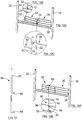
- Figure 20 shows a barrier 80 for use in an edge protection system 81 similar to that shown in Figure 1 but which will be described in more detail in relation to Figure 21 .
- the barrier 80 is constructed from hollow metal tubing with a substantially square cross-section and comprises a first upright 82 and a second upright 84 of substantially similar height.
- a laterally extending body 86 extends from the top of each upright 82, 84 to approximately two thirds of the distance down the uprights 82, 84.
- the uprights 82, 84 are horizontally spaced along the body 86 and are slidably moveable along the lateral length of the body 86.
- the lower ends 88, 90 of the uprights 82, 84 constitute, in use, plugs for engagement in complementary sockets 12 and sleeves 14, as illustrated in Figure 21 .
- the lower ends 88, 90 of the barrier 80 are located into respective adjacent sockets 12 and sleeves 14.
- the body 86 comprises an upper and a lower horizontal bar 92, 94 and an intermediate horizontal bar 96 provided midway therebetween.
- a vertical support post 98 is provided between the upper and lower horizontal bars 92, 94 and is fixedly attached by pins (not shown) to the centres of the upper, lower and intermediate bars 92, 94, 96 to give the body 86 a rigid structure.
- the support post 98 also minimises the deflection of the upper, lower and intermediate horizontal bars 92, 94, 96.
- the support post 98 is provided such that the maximum cantilever length of the upper, lower and intermediate horizontal bars 92, 94, 96 is 1m (although in other applications this may be different, e.g. 0.5m).
- Metal Sleeves 100 are provided at the points where the first and second uprights 82, 84 overlap with the upper, lower and intermediate bars 92, 94, 96 of the body 86.
- the metal sleeves 100 are configured to allow the first and second uprights 82, 84 to slide along the length of the upper, lower and intermediate bars 92, 94, 96 so as to adjust their relative position along the length of the body 86.
- a locking means in the form of a screw 102 is provided on at least one of the metal sleeves 100 of each upright 82, 84 to fix the position of the uprights 82, 84 with respect to the body 86.
- each upright 82, 84 are two vertically spaced apart attachment means in the form of carabiners 104.
- the carabiners 104 are pivotally mounted on the uprights 82, 84 and are configured for attachment to a mesh panel as will be explained below.
- the barrier 80 can be employed in an edge protection system 81 similar to that shown in Figure 1 but in which nine sockets 12, provided with respective sleeves 14, are welded onto the base I-beam 20 between adjacent vertical I-beam supports 22.
- the spacing between adjacent sockets 12 is constant in this embodiment (in use they are generally 1m apart but for shorter beams they may be 0.85m apart).
- a number of barriers 80 are supplied with the uprights 82, 84 locked a set distance (e.g. 1m) apart and with the support post 98 provided midway between the uprights 82, 84.
- Each barrier 80 is then mounted with the lower ends 88, 90 of its uprights 82, 84 in adjacent sockets 12 such that the bodies 86 are positioned end to end where possible. If the uprights 82, 84 do not align exactly with the sockets 12 one or both uprights 82, 84 can be slid to the required position before being mounted in the sockets 12 as illustrated in Figure 21 . Thus, no hot works are required on site for fixing or adjusting the positions of the sockets 12.
- each barrier 80 is mounted such that the end of the body 86 of one barrier 80 abuts the end of the body 86 of the next barrier 80.
- the end barrier 80 can be rotated through 180 degrees with respect to the orientation of the next adjacent barrier 80 to allow room for the bodies 86 of each barrier 80 to overlap.
- the relative positions of the uprights 82, 84 with respect to the body 86 can then be adjusted such that when mounted in the sockets 12, a larger proportion of the body 86 extends away from the nearest vertical I-beam support 22 than towards it. This ensures that the edge protection system 81 extends the full length of the beam 20.
- the edge protection system 81 In use, it would now be possible for the edge protection system 81 to be raised to height and work commenced on the structure. However, it is also possible to fit an optional mesh panel 110 to the edge protection system 81 for additional containment, as illustrated in Figure 23A .
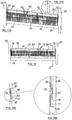
- the mesh panel 110 comprises a rectangular array constructed from a number of vertical and horizontal metal rods 112, 114 with a solid elongate rectangular toe board 106 provided along approximately its lower fifth. The gaps created by the array are approximately 100x200mm.
- the mesh panel 110 is attached to the barrier 80 via the carabiners 104 which clasp hold of an adjacent horizontal metal rod 114 of the array.
- the carabiners 104 may be configured to rotate through any given range of movement (e.g. 90°, 180° or 360°) with respect to the barrier 80.
- a number of mesh panels 110 can be placed end to end and attached to adjacent barriers 80 via respective carabiners 104 to provide improved containment along the length of the edge protection system 81. Where there is not enough room at the end of the beam 20 to place another mesh panel 110 end to end, it can overlap with the previous mesh panel 110 to ensure that no gaps are left.
- a supplementary (top-up) mesh panel 120 can be provided to increase the height of the mesh to, say, 2m.
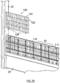
- Figures 26 , 27A and 27B illustrate attachment of one supplementary mesh panel 120 to the edge protection system 81.
- the supplementary mesh panel 120 is of a similar size to that of the mesh panel 110 but does not include the toe board 106. Accordingly, the supplementary mesh panel 120 simply comprises a rectangular array constructed from a number of vertical and horizontal metal rods 122, 124 similar to those of the mesh panel 110.
- the supplementary mesh panel 120 includes an anti-roll device constituted by two spaced apart U-shaped stirrups 126 depending from the bottom horizontal metal rod 124.
- the stirrups 126 are offset from the base of the supplementary mesh panel 120 so that they can be tucked behind a horizontal metal rod 114 of a mesh panel 110 mounted therebelow - with the remainder of the lower portion of supplementary mesh panel 120 being provided in front of the mesh panel 110, the stirrups 126 prevent the supplementary barrier from rotating backwards about a horizontal axis when in use.
- the uppermost carabiners 104 can also be attached to an adjacent horizontal metal bar 124 of the supplementary mesh panel 120 to secure it in place.
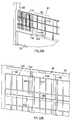
- a number of supplementary mesh panels 120 can be placed end to end and attached to adjacent barriers 80 via respective carabiners 104 to provide improved containment along the length of the edge protection system 81, as shown in Figures 28 and 29 . Where there is not enough room at the end of the beam 20 to place another supplementary mesh panel 120 end to end, it can overlap with the previous supplementary mesh panel 120 to ensure that no gaps are left.
- individual mesh panels 110 can be lifted to provide local access through the edge protection system 81 when required (e.g. for fixing cladding brackets). This is achieved by unclipping the mesh panel 110 concerned from the respective carabiners 104, lifting the mesh panel 110 to the required height, and re-attaching the carabiners 104 to the next adjacent (i.e. lower) horizontal metal bar 114. In some embodiments this can provide a work-through area 130 of approximately 550mm 2 .
- the barrier 80 and/or the mesh panels 110, 120 are made from steel or aluminium. It is also possible to supply 40m of edge protection 81 according to the present invention by supplying a stack of barriers 80 2m long by 1.4m wide by 0.7m high for transporting to the required site. In addition, 140m of mesh panel 110, 120 can be provided in a 0.7m high stack for transporting to the required site.
- FIG. 31A and 31B there is illustrated part of an edge protection system 210 in accordance with the present invention.
- the part of the edge protection system 210 shown in these Figures comprises a barrier 212 which is similar to that described above in relation to Figure 20 but is now fitted with two adjustment devices 214.
- the barrier 212 is constructed from hollow metal tubing with a substantially square cross-section and comprises a first upright 82 and a second upright 84 of substantially similar height.
- a laterally extending body 86 extends from the top of each upright 82, 84 to approximately two thirds of the distance down the uprights 82, 84.
- the uprights 82, 84 are horizontally spaced along the body 86 and are slidably moveable along the lateral length of the body 86.
- the lower ends 88, 90 of the uprights 82, 84 constitute, in use, plugs for engagement in complementary support sockets and sleeves (not shown).
- the lower ends 88, 90 of the barrier 212 are located into respective adjacent sockets and sleeves provided on a base element (not shown).
- the body 86 comprises an upper and a lower horizontal bar 92, 94 and an intermediate horizontal bar 96 provided midway therebetween.
- a vertical support post 98 is provided between the upper and lower horizontal bars 92, 94 and is fixedly attached by pins (not shown) to the centres of the upper, lower and intermediate bars 92, 94, 96 to give the body 86 a rigid structure.
- the support post 98 also minimises the deflection of the upper, lower and intermediate horizontal bars 92, 94, 96.
- the support post 98 is provided such that the maximum cantilever length of the upper, lower and intermediate horizontal bars 92, 94, 96 is 1m (although in other applications this may be different, e.g. 0.5m).
- Metal Sleeves 100 are provided at the points where the first and second uprights 82, 84 overlap with the upper, lower and intermediate bars 92, 94, 96 of the body 86.
- the metal sleeves 100 are configured to allow the first and second uprights 82, 84 to slide along the length of the upper, lower and intermediate bars 92, 94, 96 so as to adjust their relative position along the length of the body 86.
- a locking element in the form of a screw 102 is provided on at least one of the metal sleeves 100 of each upright 82, 84 to fix the position of the uprights 82, 84 with respect to the body 86.
- a stop nut (not shown) may also be provided at the ends of the horizontal bars 92, 94, 96 to prevent the uprights 82, 84 from sliding completely off the body 86.
- the adjustment devices 214 are provided on the inner facing portions at the top of each upright 82, 84 and these will be described in more detail below.
- the attachment means is in the form of a carabiner 204 which is rotatably mounted on the support post 98 between the lower and intermediate horizontal bars 94, 96. Whilst the carabiner 204 is configured for attachment to a mesh panel as will be explained below, unlike with the adjustment means 214, this particular carabiner 204 is not moveable with respect to the barrier 212.
- the adjustment device 214 comprises a base unit in the form of a U-shaped channel 220 which can be welded onto the barrier 212 with its sides 222 projecting towards the upright 82, 84 to which it is attached and its base 224 projecting outwardly there-from.
- a profiled slot 226 is provided in the base 224 and includes a generally vertically extending portion 228 having, in this case, five semi-circular cut-outs 230 along one side thereof.
- An attachment means in the form of a carabiner 232 with a spring-loaded clasp 234 is moveably mounted in the slot 226 by a roll pin 236 which connects the carabiner 232 to a locking means 238.
- the roll pin 236 is formed from an elongate metal strip which is rolled into a cylindrical form with a gap along one side which permits the pin 236 to be compressed into a hole and then to expand to fix the pin 236 in position.
- the locking means 238 is shown in detail in Figures 34A and 34B and comprises a bolt 246 with a hollow substantially cylindrical shank 248 and enlarged head 250. Beneath the enlarged head 250 there is provided a semi-circular cut-out 252 in the shank 248. Also provided towards the centre of the shank 248 is a transverse hole 254. In use, the head 250 of the bolt 246 is provided within the U-shaped channel 220 with the shank 248 projecting through the slot 226 and then through a generally circular hole 244 provided at one end of the carabiner 232.
- the hole 254 in the bolt 246 is aligned with corresponding holes 256 in the parts of the carabiner 232 which surround the bolt 246 and the roll pin 236 is inserted through the holes 254 and 256 so as to couple the carabiner 232 to the locking means 238.
- carabiner 232 will be fixedly attached to the locking means 238 in a pre-determined configured so as to operate in the manner described below.
- a washer 242 is provided between the base 224 and the carabiner 232 to act as a spacer and serves to permit the carabiner 232 and locking means 238 to rotate relative to the base 224.
- the carabiner 232, roll pin 236 and locking means 238 can be integrally formed.
- the carabiner 232 is positioned horizontally, it will be understood that under normal operation, the carabiner 232 will swing to a vertical position under gravity. In such a vertical position the bolt 246 will rotate such that the slot 252 will not be aligned to permit the carabiner 232 to be slid vertically along the slot 226. However, when the carabiner 232 is rotated to a horizontal position, as shown, the slot 252 will be aligned within the slot 226 to permit the carabiner 232 to be repositioned.
- the open configuration of the barrier 212 allows safe access beyond the confines of the edge protection system 210.
- steel mesh panels (not shown) can be located on the barrier 212 to provide increased containment.
- a mesh panel can be attached to the barrier 212 via the carabiners 204 and 232 since these can clasp hold of an adjacent horizontal metal rod of the mesh panel.
- the present invention can be used to adjust the height of such a mesh panel (relative to the barrier 212) by simply re-positioning the carabiners 232 as described above and re-attaching the mesh panels at the new height. Accordingly, the height of an edge protection system can be quickly and easily adjusted to compensate for the height of a concrete slab once cast.
- the various aspects of the invention may be employed in conjunction with a debris net.
- the debris net may be secured to a soffit of the building being constructed or repaired via an eye bolt which is screwed into a V-nut provided in an inwardly inclined channel in the soffit.
- One or more weights may be attached to the base of the net to ensure that it hangs approximately vertically and is not inadvertently repositioned to reduce containment.
- the net may be configured such that openings can be selectively provided where greater access beyond the net is required.
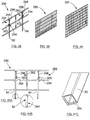
- a post 260 is shown in Figure 35 and comprises an elongate hollow tubular member 262 having a substantially square cross-section. Towards a lower end of the post 260 the outer dimensions of the tubular member 262 are reduced to form an insert 264. Projecting from at least one side of the insert 264 is a spring-biased locking member 266.
- the locking member 266 is arranged to protrude into a complementary hole 268 in an upper portion of an upright 88 of a barrier 210 (such as that shown in Figures 31A and 31B ), so as to provide positive engagement when the insert 264 is inserted into the top of the upright 88.
- a release button 269 is provided above the insert and is configured such that when the release button 269 is depressed, the locking member 266 is retracted into the insert 264 to allow the post 260 to be detached from the upright 88.
- An L-shaped bracket 270 is provided above the insert 264 for supporting an upper mesh barrier (not shown) of the type described in relation to Figure 26 .
- An anti-dislodge hook 272 is provided towards an upper end of the post 260, when in use.
- a tether 274 may be provided between the post 260 and the barrier 210 to secure the two components together at least while the post 260 is being inserted or removed from the barrier 210.
- the tether 274 comprises a rope tied around the post 260 and releasably secured to the metal sleeve 100 of the barrier 210 via a plastic T-shaped anchor 276 which is threaded through a metal hook 278.
- the tether may be integrated with one of the barrier 210 or the post 260.
- Figure 37 shows an enlarged view of the anti-dislodge hook 272 of the post 260 of Figure 35 , securing a mesh barrier 120 to the post 260.
- the anti-dislodge hook 272 comprises an upwardly sloping support arm 280 having a vertical lip 282 at a free end thereof and a downwardly sloping retaining arm 284 arranged to terminate below the height of the lip 282 between the lip 282 and the tubular member 262.
- a horizontal rod 124 of the mesh barrier 120 is passed over the lip 282 and located on the support arm 280 such that the retaining arm 284 prevents the mesh barrier 120 from being inadvertently detached from the post 260, for example, by simply lifting the mesh barrier 120 straight upwardly. Instead, in order to remove the mesh barrier 120, the retained horizontal rod 124 must be navigated through the gap between the retaining arm 284 and the lip 282.
- Figure 38 shows a perspective view of an alternative barrier 290 for an edge protection system.
- the barrier 290 is substantially similar to the barrier 80 shown in Figure 20 and so like reference numerals will be employed where appropriate.
- the present barrier 290 includes alternative adjustment units 292 on each of the first and second uprights 82, 84 and, as shown in more detail in Figures 41B and 41C , the lower portions of each of the first and second uprights 82, 84 are reinforced.
- the adjustment units 292 are provided to allow the height of the carabiners 294 to be adjusted relative to the uprights 82, 84. This in turn may allow a lower mesh barrier 295 such as that shown in Figure 39 to be attached to the barrier 290 in a number of different positions or heights.
- the adjustment unit 292 comprises a support 296 attached to the uprights 82, 84 at its upper and lower ends. Along the length of the support 296 there are provided a number of vertically spaced apart holes 298.
- a spring-pin slider plate 300 is mounted on the support 296 and is moveable there along.
- the carabiners 294 are rotatably mounted on the slider 300.
- the bias of the spring-pin slider plate 300 will be such that the plate is retained on the support at any height set.
- the pin When the user wishes to adjust the height of the carabiner 294 they will pull the pin outwardly against the bias of the spring to allow the plate 300 to be slid to the new position.
- the pin When the pin is released, it will locate through one of the adjacent holes 298 to again lock the plate 300 in position. Thus, no tools will be required for adjusting the height of the carabiners 294 and thereby adjusting the height of the mesh barrier 295.
- a top up kit may be provided with at least one of the barriers 290 and at least one of the lower mesh barriers 295 and may include at least one post 260 in accordance with Figure 35 and at least one upper mesh barrier 302 as shown in Figure 40 . It will be understood, that the edge protection system can be quickly and easily installed, adjusted and removed without the need for any tools.
- Figures 41A, 41B and 41C show more detail of the lower end of one of the uprights 82 of the barrier 290. Accordingly, it can be seen that the upright 82 includes an inner tubular element 304 as a reinforcement or leg stiffener. Both the upright 82 and the tubular element 304 have square cross-sections, one fitting snugly inside the other. A reinforcement is provided to ensure that the barrier 290 can withstand 100mph gusts of wind and meets relevant standards.
- Figure 42A shows a perspective view of the barrier 290 of Figures 38 and 41A being removed from intermediate elements 14 of a fixing means (not shown) provided on a an I-beam base 20 in accordance with Figure 1 , after a concrete slab 306 has been cast thereon.
- Figure 42B shows the intermediate elements 14 being removed from the base 20 and
- Figure 42C shows the concrete slab 306 after void plugs 308 have been inserted into the holes remaining in the concrete slab 306.
- Figure 43 shows a horizontal cross-sectional view through the end of the barrier 290 of Figures 38 and 41A prior to removal of the barrier 290 from the fixing means 12 and intermediate elements 14 of Figure 42A .
- the square profiles of the upright 82 and reinforcement 304 fit tightly within the circular diameters of the plastic sleeve 14 and metal socket 12. It has been found that such an arrangement can reduce movement of the barrier 290 by approximately 30%.
- the metal socket 12 will be completely enveloped by concrete when the slab 306 is cast but the plastic sleeve 14 will remain partly accessible so it that is can be removed from the socket after the uprights 82 have been removed, as shown in Figure 42B .
- the void plug 308 shown in Figure 44 which may be made of plastic or steel.
- the void plug 308 comprises a hollow cylindrical body 310 configured to fit snugly within the socket 12 plus an oversized lid 312 configured to rest on the top surface of the socket 12 and to lie approximately flush with the surrounding cast concrete slab 306 as illustrated in Figure 45 .
- the void plug 308 will be made slightly larger than the hole it is designed to fill so that when it is forced into the hole (e.g.
- the void plug 308 can eliminate the need for 'wet works' to complete the concrete slab 306 - again, improving the safety of the workers and speeding up and simplifying the construction process.
- Figure 46 shows a perspective view of an alternative fixing means 320 for the uprights 82, 84 of the barrier 290 of Figures 38 and 41A .
- the alternative fixing means 320 is substantially as described in the applicant's co-pending European patent application number EP 2,065,537 .
- the fixing means 320 may be screwed directly into a cast concrete slab 306 as shown.
- Figures 47A and 47B show perspective views of an unloaded and loaded material handing unit 330 for use with an edge protection system.
- the material handing unit 330 comprises a cuboidal frame 332 having four feet 334 provided at the lower end of each corner post 336, two spaced-apart transverse base posts 338, opposed horizontal side bars 340 and two centre bars 342 extending between the horizontal side bars 340.
- Two handling hooks 344 are provided on each of the front and rear top posts 346 and further handling hooks 348 are provided on the centre bars 342.
- the frame 332 is approximately 1m wide, 1.2m deep and 2m tall.
- a material handing unit 330 of this type may have a maximum capacity of 65 lower barriers 295 (weighing a total of approximately 750kg), 65 upper barriers 302 (weighing a total of approximately 900kg) or 10 barriers 290 (weighing a total of approximately 260kg).
- Figure 47B shows the material handling unit 330 of Figure 47A loaded with various components of an edge protection system.
- the unit 330 is carrying eight sets of components (each set comprising one barrier 290, one lower mesh barrier 295 and one upper mesh barrier 302) weighing a total of approximately 420kg. It will be understood that components will be loaded into the frame 332 from the sides while the centre bars 342 are not present. The centre bars 342 will then be fed through the frame 332 and components and secured to the side bars 340 to retain the components on the handling unit 330.
- the material handling unit 330 has been designed so that two such units can be accommodated on a standard hoist platform when loaded.
- Figure 48A shows a side view of an edge protection system, prior to the casting of a concrete slab 306.
- the edge protection system comprises a barrier 290 mounted in a sleeve 14 within a socket 12 and having a mesh barrier 295 secured to the barrier 290 via carabiners 294 provided at a first (low) position with respect to the barrier 290.
- Figure 48B shows a view of the edge protection system of figure 48A including the additional post 260 of Figure 35 and the upper mesh barrier 302 of Figure 40 .
- Figure 49A shows a side view of the edge protection system of Figure 48A , after the concrete slab 306 has been cast and showing that the carabiner 294 and the lower mesh barrier 295 has been raised to accommodate the slab 306.
- Figure 49B shows a side view of the edge protection system of Figure 48B , after the concrete slab 306 has been cast and showing that the carabiner 294 the lower mesh barrier 295 has been raised to accommodate the slab 306.
- the upper mesh barrier 302 remains in the same position as in Figure 48B while the lower mesh barrier 295 is raised to overlap with the base of the upper mesh barrier 302 so as to allow concrete to be poured around the fixings 12. Accordingly, a high level of containment can be maintained even when casting concrete slabs 306.
- the height of the edge protection system in Figures 48A and 48B may be approximately 1.15m and the height of the of the extended edge protection system in Figures 49A and 49B may be approximately 2.6m to 2.8m
- the various aspects of the present invention can offer many advantages to many trades.
- the steel erector's job is simplified by requiring only a few standard components that can be adjusted to fit any space.
- the acts of metal decking, laying concrete, cladding and removing the edge protection are also facilitated by aspects of the invention making the whole process safer and more efficient.
Landscapes
- Engineering & Computer Science (AREA)
- Architecture (AREA)
- Mechanical Engineering (AREA)
- Civil Engineering (AREA)
- Structural Engineering (AREA)
- Emergency Lowering Means (AREA)
- Helmets And Other Head Coverings (AREA)
- Conveying And Assembling Of Building Elements In Situ (AREA)
Claims (1)
- Kantenschutzsystem für eine Basis (20), das Befestigungsmittel (12), die Buchsen (12) und Hülsen (14) sind, die an der Basis befestigbar oder einstückig damit sind, und eine Barriere (80), die für lösbaren Eingriff mit den Befestigungsmittel konfiguriert ist, um die Barriere auf der Basis zu halten, wenn die Basis in eine Arbeitsposition angehoben ist, umfasst, wobei die Barriere mindestens zwei Pfosten (82, 84) und eine Gitterplatte (110) mit einer rechteckigen Stangenanordnung umfasst, wobei der mindestens eine Pfosten (82, 84) mit einem sich seitlich erstreckenden Körper (86) gekoppelt ist,wobei die zwei Pfosten entlang des Körpers (86) beabstandet und entlang der seitlichen Länge des Körpers gleitend bewegbar sind,wobei die unteren Enden (88, 90) der Pfosten (82, 84) bei Verwendung Stopfen zum komplementären Eingriff in die Buchsen (12) und Hülsen (14) bilden,wobei sich der sich seitlich erstreckende Körper (86) von der Oberseite jedes des mindestens einen Pfostens (82, 84) bis zu zwei Dritteln des mindestens einen Pfostens (82, 84) nach unten erstreckt und eine obere und eine untere horizontale Stange (92, 94) und eine horizontale Zwischenstange (96), die auf halbem Weg dazwischen vorgesehen sind, und eine vertikale Tragestütze (98) zwischen der oberen und der unteren horizontalen Stange (92, 94) vorgesehen ist und mit Stiften fest an den Mittelpunkten der oberen, unteren und mittleren Stange (92, 94, 96) befestigt ist, um dem Körper (86) eine starre Struktur zu geben, und Metallhülsen 100 an den Punkten bereitgestellt sind, an denen der erste und zweite Pfosten (82, 84) mit der oberen, unteren und mittleren Stange (92, 94, 96) des Körpers (86) überlappen,wobei die Metallhülsen (100) konfiguriert sind, um zu erlauben, dass der erste und zweite Pfosten (82, 84) entlang der Länge der oberen, unteren und mittleren Stange (92, 94, 96) gleiten, um ihre relative Position entlang der Länge des Körpers (86) einzustellen,wobei ein Verriegelungsmittel in der Form einer Schraube (102) an mindestens einer der Metallhülsen (100) jedes Pfostens (82, 84) bereitgestellt ist, um die Position der Pfosten (82, 84) in Bezug auf den Körper (86) zu fixieren,wobei die Barriere weiter an jedem Pfosten (82, 84) zwei Karabiner (104) umfasst, die schwenkbar auf den Pfosten (82, 84) angebracht sind, wobei die Karabiner (104) zur Befestigung an der Gitterplatte konfiguriert sind.
Applications Claiming Priority (4)
| Application Number | Priority Date | Filing Date | Title |
|---|---|---|---|
| GB0913927A GB0913927D0 (en) | 2009-08-10 | 2009-08-10 | Edge protection system |
| GB0913926A GB0913926D0 (en) | 2009-08-10 | 2009-08-10 | Adjustment device |
| PCT/GB2010/001509 WO2011018615A2 (en) | 2009-08-10 | 2010-08-10 | Edge protection system |
| EP10752098.3A EP2464802B1 (de) | 2009-08-10 | 2010-08-10 | Kantenschutzsystem |
Related Parent Applications (2)
| Application Number | Title | Priority Date | Filing Date |
|---|---|---|---|
| EP10752098.3A Division-Into EP2464802B1 (de) | 2009-08-10 | 2010-08-10 | Kantenschutzsystem |
| EP10752098.3A Division EP2464802B1 (de) | 2009-08-10 | 2010-08-10 | Kantenschutzsystem |
Publications (2)
| Publication Number | Publication Date |
|---|---|
| EP3159461A1 EP3159461A1 (de) | 2017-04-26 |
| EP3159461B1 true EP3159461B1 (de) | 2021-11-03 |
Family
ID=43064628
Family Applications (2)
| Application Number | Title | Priority Date | Filing Date |
|---|---|---|---|
| EP16197556.0A Active EP3159461B1 (de) | 2009-08-10 | 2010-08-10 | Kantenschutzsystem |
| EP10752098.3A Active EP2464802B1 (de) | 2009-08-10 | 2010-08-10 | Kantenschutzsystem |
Family Applications After (1)
| Application Number | Title | Priority Date | Filing Date |
|---|---|---|---|
| EP10752098.3A Active EP2464802B1 (de) | 2009-08-10 | 2010-08-10 | Kantenschutzsystem |
Country Status (2)
| Country | Link |
|---|---|
| EP (2) | EP3159461B1 (de) |
| WO (1) | WO2011018615A2 (de) |
Families Citing this family (5)
| Publication number | Priority date | Publication date | Assignee | Title |
|---|---|---|---|---|
| DE102015101788B4 (de) | 2015-02-09 | 2022-06-30 | SafetyNet GmbH | Sicherheitssystem für den Hochbau und dessen Verwendung |
| DE202015100594U1 (de) | 2015-02-09 | 2015-04-15 | SafetyNet GmbH | Sicherungssystem für den Hochbau |
| GB201800361D0 (en) * | 2018-01-10 | 2018-02-21 | Rapid Eps Ltd | Safety barrier apparatus and method of use thereof |
| CN110331849B (zh) * | 2019-07-10 | 2021-11-16 | 长江精工钢结构(集团)股份有限公司 | 一种建筑施工用外墙作业装置及其操作方法 |
| CN111927097A (zh) * | 2020-07-09 | 2020-11-13 | 福建建工集团有限责任公司 | 一种门窗洞口过梁以上一次性浇筑混凝土防裂缝施工方法 |
Citations (1)
| Publication number | Priority date | Publication date | Assignee | Title |
|---|---|---|---|---|
| FR2925546A1 (fr) * | 2007-12-21 | 2009-06-26 | Frenehard Et Michaux Sa Ets | Garde-corps a securite amelioree |
Family Cites Families (15)
| Publication number | Priority date | Publication date | Assignee | Title |
|---|---|---|---|---|
| DE1212707B (de) * | 1960-11-15 | 1966-03-17 | Schlotheimer Netz Und Seilerwa | Arbeitsverfahren mit Schutznetzen beim Errichten von Gebaeuden nach der Tafelbauweise |
| US3521332A (en) * | 1968-03-04 | 1970-07-21 | Roy G Kramer | Double ended clip |
| US6038829A (en) * | 1997-06-09 | 2000-03-21 | Franks; Bert | Adaptable safety rail system for flat roofs and parapets |
| US6220577B1 (en) * | 1998-07-17 | 2001-04-24 | Paul Ostrow | Temporary guard railing |
| DE20001948U1 (de) * | 2000-02-03 | 2000-03-23 | Baumann Verwertungsgesellschaft Gmbh, 88471 Laupheim | Im Bauwesen zu verwendendes Schutzgerüst |
| DE20107666U1 (de) * | 2001-05-05 | 2001-07-26 | Eckenbrecht, Friedrich, 91448 Emskirchen | Geländerartige Arbeitsschutzvorrichtung |
| JP3904873B2 (ja) * | 2001-10-02 | 2007-04-11 | ジャパン スチールス インターナショナル株式会社 | 手摺支柱および仮設手摺 |
| US20030178253A1 (en) * | 2002-03-21 | 2003-09-25 | Tatge Robert J. | Portable aircraft maintenance platform |
| CA2481681A1 (en) * | 2004-09-15 | 2006-03-15 | Larry Eisenkrein | Modular safety railing system |
| EP1820920B1 (de) | 2006-01-24 | 2017-10-18 | Combisafe International Ab | Sicherheitspfosten |
| GB0614108D0 (en) * | 2006-07-15 | 2006-08-23 | Combisafe Int Ab | Scaffolding system |
| US20080128205A1 (en) * | 2006-12-04 | 2008-06-05 | Dave Berlin | Snap-on cross brace for docks, decks and scaffolds |
| EP2122085B1 (de) * | 2007-01-19 | 2015-12-09 | Workright Edge Protection Systems Pty Ltd | Sperranordnung |
| EP2065537B1 (de) | 2007-11-30 | 2013-10-23 | Combisafe International Ab | Pfostenhalter |
| CA2616389A1 (en) * | 2007-12-21 | 2009-06-24 | Joseph Carvalho | Reusable temporary safety rail post |
-
2010
- 2010-08-10 EP EP16197556.0A patent/EP3159461B1/de active Active
- 2010-08-10 WO PCT/GB2010/001509 patent/WO2011018615A2/en not_active Ceased
- 2010-08-10 EP EP10752098.3A patent/EP2464802B1/de active Active
Patent Citations (1)
| Publication number | Priority date | Publication date | Assignee | Title |
|---|---|---|---|---|
| FR2925546A1 (fr) * | 2007-12-21 | 2009-06-26 | Frenehard Et Michaux Sa Ets | Garde-corps a securite amelioree |
Also Published As
| Publication number | Publication date |
|---|---|
| WO2011018615A2 (en) | 2011-02-17 |
| EP2464802B1 (de) | 2018-01-24 |
| WO2011018615A8 (en) | 2012-03-15 |
| EP3159461A1 (de) | 2017-04-26 |
| WO2011018615A3 (en) | 2011-04-14 |
| EP2464802A2 (de) | 2012-06-20 |
Similar Documents
| Publication | Publication Date | Title |
|---|---|---|
| US6053280A (en) | Hanging scaffold support | |
| AU2010266835B2 (en) | A slab formwork system | |
| US20120298449A1 (en) | Scaffold and methods for installing or removing such a scaffold | |
| EP3159461B1 (de) | Kantenschutzsystem | |
| CN101341306B (zh) | 应用于建筑的安全系统 | |
| WO2009009898A1 (en) | Concrete slab depth varying system | |
| CN110259088B (zh) | 具有扭曲立面的建筑物的外防护脚手架的搭设方法 | |
| US20080264725A1 (en) | Hook-On Scaffold | |
| AU2014224104B2 (en) | Construction Site Safety Screen System | |
| US20020166722A1 (en) | Mobile outrigger scaffolding system | |
| WO2005124057A1 (en) | Fittings for builders' trestles | |
| CN111219046B (zh) | 一种复合型脚手架搭设结构及其施工工艺 | |
| KR200464842Y1 (ko) | 안전 난간장치 | |
| CN113279569B (zh) | 超高楼层水平模板早拆头支撑方法 | |
| CN111519891A (zh) | 一种锚环扣接式刚性外架连墙件及其施工方法 | |
| KR20240123111A (ko) | 비계 설치 및 해체 공정을 생략한 가설물 시공방법 | |
| AU2007254713A1 (en) | Scaffolding System | |
| CN221031305U (zh) | 一种悬挑操作平台装置 | |
| CN219327290U (zh) | 一种临边操作平台 | |
| AU2003101011A4 (en) | Scaffolding apparatus | |
| AU2009311252B2 (en) | Scaffold system | |
| KR102728931B1 (ko) | 가설프레임의 작업발판 설치용 지지대 | |
| WO1999009275A1 (en) | Scaffolding and apparatus for use with scaffolding | |
| KR100538091B1 (ko) | 접힘이 가능한 수평받침대를 구비하는 거푸집 수직지지대 | |
| US20030047385A1 (en) | Mobile outrigger scaffolding system |
Legal Events
| Date | Code | Title | Description |
|---|---|---|---|
| PUAI | Public reference made under article 153(3) epc to a published international application that has entered the european phase |
Free format text: ORIGINAL CODE: 0009012 |
|
| STAA | Information on the status of an ep patent application or granted ep patent |
Free format text: STATUS: REQUEST FOR EXAMINATION WAS MADE |
|
| 17P | Request for examination filed |
Effective date: 20161107 |
|
| AC | Divisional application: reference to earlier application |
Ref document number: 2464802 Country of ref document: EP Kind code of ref document: P |
|
| AK | Designated contracting states |
Kind code of ref document: A1 Designated state(s): AL AT BE BG CH CY CZ DE DK EE ES FI FR GB GR HR HU IE IS IT LI LT LU LV MC MK MT NL NO PL PT RO SE SI SK SM TR |
|
| STAA | Information on the status of an ep patent application or granted ep patent |
Free format text: STATUS: EXAMINATION IS IN PROGRESS |
|
| 17Q | First examination report despatched |
Effective date: 20180328 |
|
| GRAP | Despatch of communication of intention to grant a patent |
Free format text: ORIGINAL CODE: EPIDOSNIGR1 |
|
| STAA | Information on the status of an ep patent application or granted ep patent |
Free format text: STATUS: GRANT OF PATENT IS INTENDED |
|
| INTG | Intention to grant announced |
Effective date: 20210527 |
|
| GRAS | Grant fee paid |
Free format text: ORIGINAL CODE: EPIDOSNIGR3 |
|
| GRAA | (expected) grant |
Free format text: ORIGINAL CODE: 0009210 |
|
| STAA | Information on the status of an ep patent application or granted ep patent |
Free format text: STATUS: THE PATENT HAS BEEN GRANTED |
|
| AC | Divisional application: reference to earlier application |
Ref document number: 2464802 Country of ref document: EP Kind code of ref document: P |
|
| AK | Designated contracting states |
Kind code of ref document: B1 Designated state(s): AL AT BE BG CH CY CZ DE DK EE ES FI FR GB GR HR HU IE IS IT LI LT LU LV MC MK MT NL NO PL PT RO SE SI SK SM TR |
|
| REG | Reference to a national code |
Ref country code: GB Ref legal event code: FG4D |
|
| REG | Reference to a national code |
Ref country code: AT Ref legal event code: REF Ref document number: 1444081 Country of ref document: AT Kind code of ref document: T Effective date: 20211115 Ref country code: CH Ref legal event code: EP |
|
| REG | Reference to a national code |
Ref country code: IE Ref legal event code: FG4D |
|
| REG | Reference to a national code |
Ref country code: DE Ref legal event code: R096 Ref document number: 602010067776 Country of ref document: DE |
|
| REG | Reference to a national code |
Ref country code: LT Ref legal event code: MG9D |
|
| REG | Reference to a national code |
Ref country code: NL Ref legal event code: MP Effective date: 20211103 |
|
| REG | Reference to a national code |
Ref country code: AT Ref legal event code: MK05 Ref document number: 1444081 Country of ref document: AT Kind code of ref document: T Effective date: 20211103 |
|
| PG25 | Lapsed in a contracting state [announced via postgrant information from national office to epo] |
Ref country code: LT Free format text: LAPSE BECAUSE OF FAILURE TO SUBMIT A TRANSLATION OF THE DESCRIPTION OR TO PAY THE FEE WITHIN THE PRESCRIBED TIME-LIMIT Effective date: 20211103 Ref country code: FI Free format text: LAPSE BECAUSE OF FAILURE TO SUBMIT A TRANSLATION OF THE DESCRIPTION OR TO PAY THE FEE WITHIN THE PRESCRIBED TIME-LIMIT Effective date: 20211103 Ref country code: BG Free format text: LAPSE BECAUSE OF FAILURE TO SUBMIT A TRANSLATION OF THE DESCRIPTION OR TO PAY THE FEE WITHIN THE PRESCRIBED TIME-LIMIT Effective date: 20220203 Ref country code: AT Free format text: LAPSE BECAUSE OF FAILURE TO SUBMIT A TRANSLATION OF THE DESCRIPTION OR TO PAY THE FEE WITHIN THE PRESCRIBED TIME-LIMIT Effective date: 20211103 |
|
| PG25 | Lapsed in a contracting state [announced via postgrant information from national office to epo] |
Ref country code: IS Free format text: LAPSE BECAUSE OF FAILURE TO SUBMIT A TRANSLATION OF THE DESCRIPTION OR TO PAY THE FEE WITHIN THE PRESCRIBED TIME-LIMIT Effective date: 20220303 Ref country code: SE Free format text: LAPSE BECAUSE OF FAILURE TO SUBMIT A TRANSLATION OF THE DESCRIPTION OR TO PAY THE FEE WITHIN THE PRESCRIBED TIME-LIMIT Effective date: 20211103 Ref country code: PT Free format text: LAPSE BECAUSE OF FAILURE TO SUBMIT A TRANSLATION OF THE DESCRIPTION OR TO PAY THE FEE WITHIN THE PRESCRIBED TIME-LIMIT Effective date: 20220303 Ref country code: PL Free format text: LAPSE BECAUSE OF FAILURE TO SUBMIT A TRANSLATION OF THE DESCRIPTION OR TO PAY THE FEE WITHIN THE PRESCRIBED TIME-LIMIT Effective date: 20211103 Ref country code: NO Free format text: LAPSE BECAUSE OF FAILURE TO SUBMIT A TRANSLATION OF THE DESCRIPTION OR TO PAY THE FEE WITHIN THE PRESCRIBED TIME-LIMIT Effective date: 20220203 Ref country code: NL Free format text: LAPSE BECAUSE OF FAILURE TO SUBMIT A TRANSLATION OF THE DESCRIPTION OR TO PAY THE FEE WITHIN THE PRESCRIBED TIME-LIMIT Effective date: 20211103 Ref country code: LV Free format text: LAPSE BECAUSE OF FAILURE TO SUBMIT A TRANSLATION OF THE DESCRIPTION OR TO PAY THE FEE WITHIN THE PRESCRIBED TIME-LIMIT Effective date: 20211103 Ref country code: HR Free format text: LAPSE BECAUSE OF FAILURE TO SUBMIT A TRANSLATION OF THE DESCRIPTION OR TO PAY THE FEE WITHIN THE PRESCRIBED TIME-LIMIT Effective date: 20211103 Ref country code: GR Free format text: LAPSE BECAUSE OF FAILURE TO SUBMIT A TRANSLATION OF THE DESCRIPTION OR TO PAY THE FEE WITHIN THE PRESCRIBED TIME-LIMIT Effective date: 20220204 Ref country code: ES Free format text: LAPSE BECAUSE OF FAILURE TO SUBMIT A TRANSLATION OF THE DESCRIPTION OR TO PAY THE FEE WITHIN THE PRESCRIBED TIME-LIMIT Effective date: 20211103 |
|
| PG25 | Lapsed in a contracting state [announced via postgrant information from national office to epo] |
Ref country code: SM Free format text: LAPSE BECAUSE OF FAILURE TO SUBMIT A TRANSLATION OF THE DESCRIPTION OR TO PAY THE FEE WITHIN THE PRESCRIBED TIME-LIMIT Effective date: 20211103 Ref country code: SK Free format text: LAPSE BECAUSE OF FAILURE TO SUBMIT A TRANSLATION OF THE DESCRIPTION OR TO PAY THE FEE WITHIN THE PRESCRIBED TIME-LIMIT Effective date: 20211103 Ref country code: RO Free format text: LAPSE BECAUSE OF FAILURE TO SUBMIT A TRANSLATION OF THE DESCRIPTION OR TO PAY THE FEE WITHIN THE PRESCRIBED TIME-LIMIT Effective date: 20211103 Ref country code: EE Free format text: LAPSE BECAUSE OF FAILURE TO SUBMIT A TRANSLATION OF THE DESCRIPTION OR TO PAY THE FEE WITHIN THE PRESCRIBED TIME-LIMIT Effective date: 20211103 Ref country code: DK Free format text: LAPSE BECAUSE OF FAILURE TO SUBMIT A TRANSLATION OF THE DESCRIPTION OR TO PAY THE FEE WITHIN THE PRESCRIBED TIME-LIMIT Effective date: 20211103 Ref country code: CZ Free format text: LAPSE BECAUSE OF FAILURE TO SUBMIT A TRANSLATION OF THE DESCRIPTION OR TO PAY THE FEE WITHIN THE PRESCRIBED TIME-LIMIT Effective date: 20211103 |
|
| REG | Reference to a national code |
Ref country code: DE Ref legal event code: R097 Ref document number: 602010067776 Country of ref document: DE |
|
| PLBE | No opposition filed within time limit |
Free format text: ORIGINAL CODE: 0009261 |
|
| STAA | Information on the status of an ep patent application or granted ep patent |
Free format text: STATUS: NO OPPOSITION FILED WITHIN TIME LIMIT |
|
| 26N | No opposition filed |
Effective date: 20220804 |
|
| PG25 | Lapsed in a contracting state [announced via postgrant information from national office to epo] |
Ref country code: AL Free format text: LAPSE BECAUSE OF FAILURE TO SUBMIT A TRANSLATION OF THE DESCRIPTION OR TO PAY THE FEE WITHIN THE PRESCRIBED TIME-LIMIT Effective date: 20211103 |
|
| PG25 | Lapsed in a contracting state [announced via postgrant information from national office to epo] |
Ref country code: SI Free format text: LAPSE BECAUSE OF FAILURE TO SUBMIT A TRANSLATION OF THE DESCRIPTION OR TO PAY THE FEE WITHIN THE PRESCRIBED TIME-LIMIT Effective date: 20211103 |
|
| PG25 | Lapsed in a contracting state [announced via postgrant information from national office to epo] |
Ref country code: MC Free format text: LAPSE BECAUSE OF FAILURE TO SUBMIT A TRANSLATION OF THE DESCRIPTION OR TO PAY THE FEE WITHIN THE PRESCRIBED TIME-LIMIT Effective date: 20211103 |
|
| REG | Reference to a national code |
Ref country code: CH Ref legal event code: PL |
|
| PG25 | Lapsed in a contracting state [announced via postgrant information from national office to epo] |
Ref country code: LU Free format text: LAPSE BECAUSE OF NON-PAYMENT OF DUE FEES Effective date: 20220810 Ref country code: LI Free format text: LAPSE BECAUSE OF NON-PAYMENT OF DUE FEES Effective date: 20220831 Ref country code: CH Free format text: LAPSE BECAUSE OF NON-PAYMENT OF DUE FEES Effective date: 20220831 |
|
| REG | Reference to a national code |
Ref country code: BE Ref legal event code: MM Effective date: 20220831 |
|
| PG25 | Lapsed in a contracting state [announced via postgrant information from national office to epo] |
Ref country code: IT Free format text: LAPSE BECAUSE OF FAILURE TO SUBMIT A TRANSLATION OF THE DESCRIPTION OR TO PAY THE FEE WITHIN THE PRESCRIBED TIME-LIMIT Effective date: 20211103 |
|
| PG25 | Lapsed in a contracting state [announced via postgrant information from national office to epo] |
Ref country code: IE Free format text: LAPSE BECAUSE OF NON-PAYMENT OF DUE FEES Effective date: 20220810 |
|
| PG25 | Lapsed in a contracting state [announced via postgrant information from national office to epo] |
Ref country code: BE Free format text: LAPSE BECAUSE OF NON-PAYMENT OF DUE FEES Effective date: 20220831 |
|
| PG25 | Lapsed in a contracting state [announced via postgrant information from national office to epo] |
Ref country code: HU Free format text: LAPSE BECAUSE OF FAILURE TO SUBMIT A TRANSLATION OF THE DESCRIPTION OR TO PAY THE FEE WITHIN THE PRESCRIBED TIME-LIMIT; INVALID AB INITIO Effective date: 20100810 |
|
| PG25 | Lapsed in a contracting state [announced via postgrant information from national office to epo] |
Ref country code: CY Free format text: LAPSE BECAUSE OF FAILURE TO SUBMIT A TRANSLATION OF THE DESCRIPTION OR TO PAY THE FEE WITHIN THE PRESCRIBED TIME-LIMIT Effective date: 20211103 |
|
| PG25 | Lapsed in a contracting state [announced via postgrant information from national office to epo] |
Ref country code: MK Free format text: LAPSE BECAUSE OF FAILURE TO SUBMIT A TRANSLATION OF THE DESCRIPTION OR TO PAY THE FEE WITHIN THE PRESCRIBED TIME-LIMIT Effective date: 20211103 |
|
| PG25 | Lapsed in a contracting state [announced via postgrant information from national office to epo] |
Ref country code: TR Free format text: LAPSE BECAUSE OF FAILURE TO SUBMIT A TRANSLATION OF THE DESCRIPTION OR TO PAY THE FEE WITHIN THE PRESCRIBED TIME-LIMIT Effective date: 20211103 |
|
| PG25 | Lapsed in a contracting state [announced via postgrant information from national office to epo] |
Ref country code: MT Free format text: LAPSE BECAUSE OF FAILURE TO SUBMIT A TRANSLATION OF THE DESCRIPTION OR TO PAY THE FEE WITHIN THE PRESCRIBED TIME-LIMIT Effective date: 20211103 |
|
| PGFP | Annual fee paid to national office [announced via postgrant information from national office to epo] |
Ref country code: DE Payment date: 20250827 Year of fee payment: 16 |
|
| PGFP | Annual fee paid to national office [announced via postgrant information from national office to epo] |
Ref country code: GB Payment date: 20250826 Year of fee payment: 16 |
|
| PGFP | Annual fee paid to national office [announced via postgrant information from national office to epo] |
Ref country code: FR Payment date: 20250825 Year of fee payment: 16 |