EP3159488A1 - Ensemble d'étanchéité et turbine associée - Google Patents
Ensemble d'étanchéité et turbine associée Download PDFInfo
- Publication number
- EP3159488A1 EP3159488A1 EP16194171.1A EP16194171A EP3159488A1 EP 3159488 A1 EP3159488 A1 EP 3159488A1 EP 16194171 A EP16194171 A EP 16194171A EP 3159488 A1 EP3159488 A1 EP 3159488A1
- Authority
- EP
- European Patent Office
- Prior art keywords
- sealing
- tooth
- turbine
- fluid
- disposed
- Prior art date
- Legal status (The legal status is an assumption and is not a legal conclusion. Google has not performed a legal analysis and makes no representation as to the accuracy of the status listed.)
- Granted
Links
Images


Classifications
-
- F—MECHANICAL ENGINEERING; LIGHTING; HEATING; WEAPONS; BLASTING
- F01—MACHINES OR ENGINES IN GENERAL; ENGINE PLANTS IN GENERAL; STEAM ENGINES
- F01D—NON-POSITIVE DISPLACEMENT MACHINES OR ENGINES, e.g. STEAM TURBINES
- F01D11/00—Preventing or minimising internal leakage of working-fluid, e.g. between stages
- F01D11/003—Preventing or minimising internal leakage of working-fluid, e.g. between stages by packing rings; Mechanical seals
-
- F—MECHANICAL ENGINEERING; LIGHTING; HEATING; WEAPONS; BLASTING
- F01—MACHINES OR ENGINES IN GENERAL; ENGINE PLANTS IN GENERAL; STEAM ENGINES
- F01D—NON-POSITIVE DISPLACEMENT MACHINES OR ENGINES, e.g. STEAM TURBINES
- F01D11/00—Preventing or minimising internal leakage of working-fluid, e.g. between stages
- F01D11/02—Preventing or minimising internal leakage of working-fluid, e.g. between stages by non-contact sealings, e.g. of labyrinth type
-
- F—MECHANICAL ENGINEERING; LIGHTING; HEATING; WEAPONS; BLASTING
- F16—ENGINEERING ELEMENTS AND UNITS; GENERAL MEASURES FOR PRODUCING AND MAINTAINING EFFECTIVE FUNCTIONING OF MACHINES OR INSTALLATIONS; THERMAL INSULATION IN GENERAL
- F16J—PISTONS; CYLINDERS; SEALINGS
- F16J15/00—Sealings
- F16J15/16—Sealings between relatively-moving surfaces
- F16J15/40—Sealings between relatively-moving surfaces by means of fluid
- F16J15/406—Sealings between relatively-moving surfaces by means of fluid by at least one pump
-
- F—MECHANICAL ENGINEERING; LIGHTING; HEATING; WEAPONS; BLASTING
- F16—ENGINEERING ELEMENTS AND UNITS; GENERAL MEASURES FOR PRODUCING AND MAINTAINING EFFECTIVE FUNCTIONING OF MACHINES OR INSTALLATIONS; THERMAL INSULATION IN GENERAL
- F16J—PISTONS; CYLINDERS; SEALINGS
- F16J15/00—Sealings
- F16J15/44—Free-space packings
- F16J15/447—Labyrinth packings
- F16J15/4472—Labyrinth packings with axial path
-
- F—MECHANICAL ENGINEERING; LIGHTING; HEATING; WEAPONS; BLASTING
- F05—INDEXING SCHEMES RELATING TO ENGINES OR PUMPS IN VARIOUS SUBCLASSES OF CLASSES F01-F04
- F05D—INDEXING SCHEME FOR ASPECTS RELATING TO NON-POSITIVE-DISPLACEMENT MACHINES OR ENGINES, GAS-TURBINES OR JET-PROPULSION PLANTS
- F05D2240/00—Components
- F05D2240/55—Seals
-
- F—MECHANICAL ENGINEERING; LIGHTING; HEATING; WEAPONS; BLASTING
- F05—INDEXING SCHEMES RELATING TO ENGINES OR PUMPS IN VARIOUS SUBCLASSES OF CLASSES F01-F04
- F05D—INDEXING SCHEME FOR ASPECTS RELATING TO NON-POSITIVE-DISPLACEMENT MACHINES OR ENGINES, GAS-TURBINES OR JET-PROPULSION PLANTS
- F05D2250/00—Geometry
- F05D2250/20—Three-dimensional
- F05D2250/25—Three-dimensional helical
Definitions
- Exemplary embodiments of the present invention relate to a sealing assembly for a turbine, and more particularly, to a sealing assembly for a turbine which is configured such that sealing between a rotating body and a fixed body of the turbine is embodied in a point contact manner, whereby a wear rate of the sealing structure can be reduced, and leakage of fluid can be effectively prevented.
- a turbine is a power generating apparatus which converts thermal energy of fluid such as gas or steam into rotating force that is mechanical energy.
- the turbine includes a rotor provided with a plurality of rotating buckets such that the rotor is axially rotated by fluid, and a casing which encloses the circumference of the rotor and is provided with a plurality of fixed diaphrams.
- a gas turbine includes a compressor, a combustor and a turbine and is configured such that, when the compressor rotates, external air is drawn into and compressed in the compressor, the compressed air is transmitted to the combustor, and then combustion is implemented by mixing the compressed air with fuel in the combustor.
- High-temperature and high-pressure gas generated from the combustor passes through the turbine and rotates the rotor of the turbine, thus driving a generator.
- a high-pressure turbine, a middle-pressure turbine and a low-pressure turbine are coupled in series or parallel with each other so as to rotate a rotor.
- the steam turbine has a serial structure
- the high-pressure turbine, the middle-pressure turbine and the low-pressure turbine share a single rotor.
- Each turbine of the steam turbine includes fixed diaphrams and rotating buckets provided around the rotor in a casing. Steam rotates the rotor while passing through the fixed buckets and the rotating diaphrams, and thus drives a generator.
- the rotating body and the fixed body In the case of the steam turbine, because high-temperature steam drawn from a boiler applies heat to the rotating body and the fixed body, they are expanded or contracted by several millimeters to several tens of millimeters depending on positions when the steam turbine is operated and stopped. In this case, the rotating body and the fixed body differentially expand or contract because of different characteristics of the materials. Furthermore, depending on the structure of the turbine, the directions in which the rotating body and the fixed body expand or contract are different from each other. Thus, the rotating body and the fixed body may cause interference with each other during the operation, thus causing rubbing.
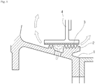
- a sealing technology in which a honeycomb seal and a labyrinth seal are used for sealing of the gas turbine or the steam turbine such that the fixed body and the rotating body make smooth contact with each other while reducing the space therebetween.
- the honeycomb seal 3 is disposed on a fixed body 4 of a turbine, and the labyrinth seal 2 is disposed on a rotating body 1 of the turbine such that it faces the honeycomb seal 3 at a position adjacent thereto.
- this structure is configured such that space between the honeycomb seal 3 and the labyrinth seal 2 is relatively small, and the number of teeth of the labyrinth seal 2 is relatively large.
- the distance may change due to vibrations or thermal expansion of the materials during the operation of the turbine, whereby a wear rate of the sealing structure increases because of rubbing. This may eventually cause damage to a blade or parts of the turbine.
- the sealing performance deteriorates, and fluid loss is caused, thus reducing the output efficiency of the turbine.
- An object of the present invention is to provide an apparatus which is configured such that sealing between a rotating body and a fixed body is embodied in a point contact manner, whereby a wear rate of the sealing structure can be reduced, and leakage of fluid can be effectively prevented.
- a sealing assembly for a turbine including: a first sealing member disposed on an inner circumferential surface of a fixed body of the turbine; and a second sealing member disposed on an outer circumferential surface of a rotating body of the turbine at a position adjacent to the first sealing member, wherein at least one of the first and second sealing members includes a tooth configured to cause fluid to flow in an axial direction of the turbine when the rotating body of the turbine rotates, and the flow of fluid offsets flow of fluid drawn into space between the fixed body and the rotating body of the turbine.
- the second sealing member may include: a second sealing body mounted to the outer circumferential surface of the rotating body of the turbine; and a second tooth wound around the second sealing body a plurality of times and disposed in a spiral shape, the second tooth being provided to protrude toward the first sealing member.
- the second tooth may have a spiral shape in a reverse direction of the flow of leakage fluid.
- the second sealing member may further include a protrusion provided on the second sealing body and disposed to be interlocked with the second tooth so that fluid is pushed outward with respect to a direction of rotation of the second sealing member.
- the protrusion may be disposed at a predetermined angle to the second tooth.
- the height of the protrusion may be less than that of the tooth.
- the protrusion may comprise a plurality of protrusions, wherein the protrusions may be disposed on a same line between parts of the second tooth.
- the protrusion may comprise a plurality of protrusions, wherein the protrusions may be provided between parts of the second tooth and disposed on different lines spaced apart from each other at regular distances.
- the first sealing member may include: a first sealing body mounted to the fixed body of the turbine; and a first tooth disposed on the first sealing body and provided to protrude toward the second sealing member.
- the first tooth and the second tooth may be configured such that when the second tooth rotates, the first and second teeth come into point contact with each other and prevent leakage of fluid.
- the first tooth may also have a spiral shape in a reverse direction of the flow of leakage fluid. That is, both the first and second teeth may have spiral shapes in the reverse direction of the flow of leakage fluid, or either the first or second tooth may have a spiral shape.
- the first tooth may comprise a plurality of first teeth, wherein at least some of the first teeth may be disposed on the first sealing body at positions spaced apart from each other at different distances.
- the plurality of first teeth may be formed on the first sealing body such that the distances therebetween are reduced from a leakage-fluid inlet region to a leakage-fluid outlet region.
- Each of the first and second sealing members may comprise a labyrinth seal.
- the first tooth and the second tooth may partially come into contact with each other.
- a turbine comprising the sealing assembly having the above-mentioned configuration.
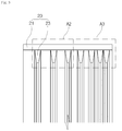
- FIG. 2 is a partial perspective view illustrating a first embodiment of a sealing assembly for a turbine according to the present invention.
- FIG. 3 is partial side view showing a fixed-body sealing structure according to the present invention shown in FIG. 2 .
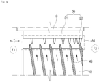
- FIG.4 is a partial side view of the present invention shown in FIG. 2 .
- FIG. 5 is a view illustrating a point contact state between sealing parts of a fixed body and a rotating body according to the present invention shown in FIG. 2 .
- the first embodiment of the sealing assembly for the turbine according to the present invention may include a first sealing member 20 and a second sealing member 40.
- the first sealing member 20 may be disposed in a circumferential direction on an inner circumferential surface of the fixed body 10 of the turbine and have a ring shape.
- the fixed body 10 of the turbine may be a concept including a fixed diaphragm and a casing of the turbine to which the fixed diaphragm is mounted.
- the first sealing member 20 may be formed of a labyrinth seal provided with a plurality of protrusions.
- the first sealing member 20 may include a first sealing body 21 and a first tooth 23.
- the first sealing body 21 may be installed in the circumferential direction on the inner circumferential surface of the fixed body 10 of the turbine.
- the first tooth 23 may be formed on the first sealing body 21 and provided to protrude toward the second sealing member 40.
- the first tooth 23 may comprise a plurality of first teeth 23. At least some of the first teeth 23 may be disposed on the first sealing body 21 at positions spaced apart from each other at different distances. Referring to FIG. 3 , it is shown that the first teeth 23 are formed on the first sealing body 21 such that the distance between the first teeth 23 is reduced from a leakage-fluid inlet region F1 to a leakage-fluid outlet region F2.
- first teeth 23 As the distance between the first teeth 23 is reduced from the leakage-fluid inlet region F1 to the leakage-fluid outlet region F2 and, in addition, the first teeth 23 are interlocked with the second sealing member (20; in detail, a second tooth which will be described later herein) in a point contact manner, leakage of fluid that flows through space between the first sealing member 20 and the second sealing member 40 can be further limited.
- the structure of the present invention can more effectively prevent leakage of fluid around the leakage-fluid outlet region F2.
- the structure of the present invention can reduce a wear rate between the first teeth 23 and the second sealing member 40.
- the fluid leakage prevention effect is enhanced, but a wear rate of the sealing structure is markedly increased because the point contact region is increased.
- the first teeth 23 be disposed on the first sealing body 21 at positions spaced apart from each other by comparatively large distances (refer to region A2 of FIG. 3 ), and, around the leakage-fluid outlet region F2, the first teeth 23 be disposed on the first sealing body 21 at positions spaced apart from each other by comparatively small distances (refer to region A3 of FIG. 3 ).
- the second sealing member 40 may face the first sealing member 20 and be provided in the circumferential direction on the outer circumferential surface of the rotating body 30 of the turbine.
- the second sealing member 40 may have a ring shape.
- the rotating body 30 of the turbine may be a concept including rotating buckets and a rotor to which the rotating buckets are mounted.
- the second sealing member 40 may be formed of a labyrinth seal.
- each of the first sealing member 20 and the second sealing member 40 are embodied by the labyrinth seal, basically, leaking fluid is reduced in hydraulic pressure each time it passes through each of a plurality of protrusions of the labyrinth seal. Consequently, the flow rate of fluid is reduced from the leakage-fluid inlet region F1 to the leakage-fluid outlet region F2, whereby leakage of fluid can be blocked or minimized.
- the second sealing member 40 may include a second sealing body 41 and a second tooth 43.
- the second sealing body 41 may be installed in the circumferential direction on the inner circumferential surface of the rotating body 30 of the turbine.
- the second tooth 43 may be provided to protrude from the second sealing body 41.
- At least some of the second tooth 43 may be formed in a spiral shape in a direction opposite to the direction in which leakage fluid flows. Referring to FIGS. 2 and 4 , there is illustrated the shape of the spiral second tooth 43 disposed on the second sealing body 41.
- first tooth 23 is circumferentially disposed in an annular shape on the first sealing body 21 and the second tooth 43 is disposed in a spiral shape on the second sealing body 41. Therefore, when the rotor rotates, the first tooth 23 and the second tooth 43 continuously make point contact (A6) with each other while rotating, thus limiting the space through which fluid leaks.
- the second tooth 43 has a spiral shape, leakage fluid can return to the leakage-fluid inlet region F1.
- the rotating body 30 of the turbine is integrally rotated, and the second sealing member 40 mounted to the rotating body 30 of the turbine is also rotated along with the rotating body 30.
- the second tooth 43 is integrally wound several times around the second sealing body 41. Therefore, when the second tooth 43 is rotated by the rotation of the rotor, leakage fluid can effectively return to the leakage-fluid inlet region F1 rater than remaining space between the first sealing member 20 and the second sealing member 40.
- the wear rate of the sealing structure is minimized by the point contact structure between the first tooth 23 and the second tooth 43 and, simultaneously, leakage of fluid can be prevented.
- leakage fluid is moved in a reverse direction of the leakage flow direction, whereby fluid can be more reliably prevented from remaining or leaking.
- FIG. 6a is a partial perspective view illustrating a second embodiment of the sealing assembly for the turbine according to the present invention.
- FIG.6b is a partial side view of the present invention shown in FIG. 6a .
- the sealing assembly for the turbine according to the second embodiment of the present invention may include a first sealing member 20 and a second sealing member 40.
- the descriptions of the disposition, shape and material of the first and second sealing members 20 and 40 are the same as those of the first embodiment of the present invention; therefore, further description will be omitted.
- the second sealing member 40 may include a second sealing body 41 and a second tooth 43.
- the second sealing body 41 may be installed in the circumferential direction on the inner circumferential surface of the rotating body 30 of the turbine.
- the second tooth 43 may be provided to protrude from the second sealing body 41.
- At least some of the second tooth 43 may be formed in a spiral shape in a direction opposite to the direction in which leakage fluid flows. Referring again to FIGS. 6a and 6b , there is illustrated the shape of the spiral second tooth 43 disposed on the second sealing body 41. However, the function of the spiral structure of the second tooth 43 is the same as that of the first embodiment of the present invention; therefore, detailed description thereof will be omitted.
- the second sealing member 40 further includes a protrusion 50.
- the protrusion 50 may be disposed to be interlocked with the second tooth 43 on the second sealing body 41 such that fluid is pushed outward with respect to the direction of the rotation of the second sealing body 41.
- a single or a plurality of protrusions 50 may be disposed at a predetermined angle between parts of the second tooth 43.
- the protrusions 50 are disposed on the same line perpendicular to the second tooth 43.
- a fluid barrier (refer to a region A5 of FIG. 6b ) may be formed. The fluid barrier impedes the flow of fluid passing through space between the first sealing member 20 and the second sealing member 40 and, ultimately, functions to prevent leakage of fluid.
- a height L2 of the protrusion 50 be less than a height L1 of the second tooth 43.
- the protrusion 50 impedes the flow of fluid that flows between the parts of the second tooth 43, thus making it difficult to move leakage fluid toward the leakage-fluid inlet region.
- the fluid barrier can be formed without impeding the flow of fluid. Therefore, the characteristics of the protrusion 50 can be more clearly derived. In more detail, it is preferable that the height of the protrusion 50 be half of the height of the second tooth 43 or less.
- the protrusion 50 may have a curved inclined part 50a on at least one side surface thereof so that fluid can be smoothly pushed outward in the direction of the rotation.
- the fluid barrier (refer to the region A5 of FIG. 6b ) can be reliably formed without causing a vortex phenomenon.
- the second embodiment of the present invention forms the fluid barrier using the protrusion 50 as well as having the effect introduced by the first embodiment, thus more reliably blocking leakage of fluid.
- FIG. 7 is a partial perspective view illustrating a third embodiment of the sealing assembly for the turbine according to the present invention.
- the sealing assembly for the turbine according to the third embodiment of the present invention may include a first sealing member 20 and a second sealing member 40.
- the descriptions of the disposition, shape and material of the first and second sealing members 20 and 40 are the same as those of the first embodiment of the present invention; therefore, further description will be omitted.
- the second sealing member 40 may include a second sealing body 41 and a second tooth 43.
- the second sealing body 41 may be installed in the circumferential direction on the inner circumferential surface of the rotating body 30 of the turbine.
- the second tooth 43 may be provided to protrude from the second sealing body 41.
- At least some of the second tooth 43 may be formed in a spiral shape in a direction opposite to the direction in which leakage fluid flows. Referring again to FIG. 7 , there is illustrated the shape of the spiral second tooth 43 disposed on the second sealing body 41. However, the function of the spiral structure of the second tooth 43 is the same as that of the first embodiment of the present invention; therefore, detailed description thereof will be omitted.
- the second sealing member 40 further includes a protrusion 50.
- the protrusion 50 may be disposed to be interlocked with the second tooth 43 on the second sealing body 41 such that fluid is pushed in the direction of the rotation of the second sealing body 41.
- a single or a plurality of protrusions 50 may be disposed at a predetermined angle between parts of the second tooth 43.
- the protrusions 50 may be disposed between the parts of the second tooth 43 on different lines spaced apart from each other at regular distances.
- the protrusions 50 are disposed between the parts of the second tooth 43 at positions spaced apart from each other at regular distances.
- reinforced fluid barriers are formed in stages with time intervals in the space between the first sealing member 20 and the second sealing member 40 so as to prevent leakage of fluid.
- the third embodiment of the present invention forms the fluid barriers using the protrusion 50 in stages with regular time intervals as well as having the effect introduced by the first embodiment, thus more reliably blocking leakage of fluid.
- sealing for preventing leakage of fluid between a rotating body and a fixed body is realized in a point contact manner, so a rubbing phenomenon of the sealing structure is mitigated, whereby a wear rate of the sealing structure can be reduced.
- the sealing part of the fixed body is configured such that the structure thereof becomes dense from a leakage-fluid inlet region to a leakage-fluid outlet region so that the point contact distances with the rotating body are reduced. Thereby, leakage of fluid can be more reliably blocked.
- the sealing part of the rotating body has a spiral shape in a reverse direction of the fluid leakage direction so as to return leaked fluid to the fluid inlet region, thus additionally preventing leakage of fluid.
- this structure can minimize the output loss of the turbine resulting from leakage of fluid and thus enhance the efficiency of the turbine.
- the contact area between the sealing part of the rotating body and the sealing part of the fixed part is reduced so that the lifetime and replacement period of the sealing parts can be extended, whereby the maintenance costs of the turbine can be reduced.
Landscapes
- Engineering & Computer Science (AREA)
- General Engineering & Computer Science (AREA)
- Mechanical Engineering (AREA)
- Sealing Using Fluids, Sealing Without Contact, And Removal Of Oil (AREA)
- Turbine Rotor Nozzle Sealing (AREA)
- Chemical & Material Sciences (AREA)
- Combustion & Propulsion (AREA)
Applications Claiming Priority (1)
| Application Number | Priority Date | Filing Date | Title |
|---|---|---|---|
| KR1020150148308A KR101741332B1 (ko) | 2015-10-23 | 2015-10-23 | 터빈의 실링 조립체 |
Publications (2)
| Publication Number | Publication Date |
|---|---|
| EP3159488A1 true EP3159488A1 (fr) | 2017-04-26 |
| EP3159488B1 EP3159488B1 (fr) | 2019-06-05 |
Family
ID=57144877
Family Applications (1)
| Application Number | Title | Priority Date | Filing Date |
|---|---|---|---|
| EP16194171.1A Active EP3159488B1 (fr) | 2015-10-23 | 2016-10-17 | Ensemble d'étanchéité et turbine associée |
Country Status (3)
| Country | Link |
|---|---|
| EP (1) | EP3159488B1 (fr) |
| KR (1) | KR101741332B1 (fr) |
| WO (1) | WO2017069391A1 (fr) |
Cited By (2)
| Publication number | Priority date | Publication date | Assignee | Title |
|---|---|---|---|---|
| CN107387170A (zh) * | 2017-08-14 | 2017-11-24 | 西北工业大学 | 一种用于轮缘密封的预旋增压转子盘结构 |
| CN112473189A (zh) * | 2020-10-21 | 2021-03-12 | 西北工业大学 | 一种航空发动机及其离心式轴心油气分离装置和方法 |
Families Citing this family (3)
| Publication number | Priority date | Publication date | Assignee | Title |
|---|---|---|---|---|
| US11293295B2 (en) | 2019-09-13 | 2022-04-05 | Pratt & Whitney Canada Corp. | Labyrinth seal with angled fins |
| KR102144584B1 (ko) | 2019-10-16 | 2020-08-13 | 주식회사 신한정공 | 수차의 실링 교체방법 |
| CN115839262B (zh) * | 2021-09-18 | 2025-05-23 | 中国航发商用航空发动机有限责任公司 | 封严篦齿结构和封严结构 |
Citations (4)
| Publication number | Priority date | Publication date | Assignee | Title |
|---|---|---|---|---|
| DE2931714A1 (de) * | 1979-07-05 | 1981-01-15 | Bbc Brown Boveri & Cie | Labyrinthdichtung |
| US20040096319A1 (en) * | 2001-03-26 | 2004-05-20 | Tatsuro Uchida | Rotary machine with seal |
| US20150040566A1 (en) * | 2013-08-06 | 2015-02-12 | General Electric Company | Helical seal system for a turbomachine |
| KR101507500B1 (ko) | 2013-09-30 | 2015-04-01 | 포스코에너지 주식회사 | 라비린스 씰 및 이를 포함하는 반작용식 스팀 터빈 |
Family Cites Families (4)
| Publication number | Priority date | Publication date | Assignee | Title |
|---|---|---|---|---|
| US4084825A (en) * | 1976-03-31 | 1978-04-18 | The United States Of America As Represented By The Administrator Of The National Aeronautics And Space Administration | Counter pumping debris excluder and separator |
| JP2008223660A (ja) * | 2007-03-14 | 2008-09-25 | Toshiba Corp | 軸シール装置およびターボ機械 |
| CN201771723U (zh) * | 2010-08-05 | 2011-03-23 | 西安陕鼓动力股份有限公司 | 一种压缩/透平机轴端组合密封 |
| DE202011105609U1 (de) * | 2011-09-12 | 2011-10-13 | Alstom Technology Ltd. | Labyrinthdichtung |
-
2015
- 2015-10-23 KR KR1020150148308A patent/KR101741332B1/ko active Active
-
2016
- 2016-08-23 WO PCT/KR2016/009324 patent/WO2017069391A1/fr not_active Ceased
- 2016-10-17 EP EP16194171.1A patent/EP3159488B1/fr active Active
Patent Citations (4)
| Publication number | Priority date | Publication date | Assignee | Title |
|---|---|---|---|---|
| DE2931714A1 (de) * | 1979-07-05 | 1981-01-15 | Bbc Brown Boveri & Cie | Labyrinthdichtung |
| US20040096319A1 (en) * | 2001-03-26 | 2004-05-20 | Tatsuro Uchida | Rotary machine with seal |
| US20150040566A1 (en) * | 2013-08-06 | 2015-02-12 | General Electric Company | Helical seal system for a turbomachine |
| KR101507500B1 (ko) | 2013-09-30 | 2015-04-01 | 포스코에너지 주식회사 | 라비린스 씰 및 이를 포함하는 반작용식 스팀 터빈 |
Cited By (4)
| Publication number | Priority date | Publication date | Assignee | Title |
|---|---|---|---|---|
| CN107387170A (zh) * | 2017-08-14 | 2017-11-24 | 西北工业大学 | 一种用于轮缘密封的预旋增压转子盘结构 |
| CN107387170B (zh) * | 2017-08-14 | 2019-05-10 | 西北工业大学 | 一种用于轮缘密封的预旋增压转子盘结构 |
| CN112473189A (zh) * | 2020-10-21 | 2021-03-12 | 西北工业大学 | 一种航空发动机及其离心式轴心油气分离装置和方法 |
| CN112473189B (zh) * | 2020-10-21 | 2022-04-05 | 西北工业大学 | 一种航空发动机及其离心式轴心油气分离装置和方法 |
Also Published As
| Publication number | Publication date |
|---|---|
| EP3159488B1 (fr) | 2019-06-05 |
| WO2017069391A1 (fr) | 2017-04-27 |
| KR101741332B1 (ko) | 2017-05-29 |
| KR20170047800A (ko) | 2017-05-08 |
Similar Documents
| Publication | Publication Date | Title |
|---|---|---|
| US10480339B2 (en) | Sealing assembly | |
| US10837301B2 (en) | Structure for multi-stage sealing of turbine | |
| EP3159488A1 (fr) | Ensemble d'étanchéité et turbine associée | |
| JP6216643B2 (ja) | スワール阻止シールを有するターボ機械 | |
| EP0979962A2 (fr) | Joint d'étanchéité et machine tournante munie d'un tel joint | |
| WO2014091599A1 (fr) | Machine à fluide rotative | |
| US20150275685A1 (en) | Face seal with locally compliant hydrodynamic pads | |
| US10060534B2 (en) | Sealing structure for turbine | |
| EP2246598B1 (fr) | Emballage de reliefs d'étanchéité de rotor | |
| JP7706881B2 (ja) | 改善されたロータブレードのシーリング構造 | |
| CN107614948B (zh) | 密封装置以及旋转机械 | |
| EP1052437A2 (fr) | Segment de joint à brosses avec amortissement des balais | |
| JP2014141912A (ja) | 回転機械 | |
| KR101695126B1 (ko) | 돌기 형상을 이용한 터빈의 실링 강화 구조 | |
| JP6712873B2 (ja) | シール構造及びターボ機械 | |
| US11905838B2 (en) | Seal member and rotary machine | |
| JP2014199059A (ja) | 端壁部材及びガスタービン | |
| US20140205440A1 (en) | Compliant plate seals for rotary machines | |
| JP2020176680A (ja) | シール装置、タービン |
Legal Events
| Date | Code | Title | Description |
|---|---|---|---|
| PUAI | Public reference made under article 153(3) epc to a published international application that has entered the european phase |
Free format text: ORIGINAL CODE: 0009012 |
|
| STAA | Information on the status of an ep patent application or granted ep patent |
Free format text: STATUS: REQUEST FOR EXAMINATION WAS MADE |
|
| 17P | Request for examination filed |
Effective date: 20161017 |
|
| AK | Designated contracting states |
Kind code of ref document: A1 Designated state(s): AL AT BE BG CH CY CZ DE DK EE ES FI FR GB GR HR HU IE IS IT LI LT LU LV MC MK MT NL NO PL PT RO RS SE SI SK SM TR |
|
| AX | Request for extension of the european patent |
Extension state: BA ME |
|
| RBV | Designated contracting states (corrected) |
Designated state(s): AL AT BE BG CH CY CZ DE DK EE ES FI FR GB GR HR HU IE IS IT LI LT LU LV MC MK MT NL NO PL PT RO RS SE SI SK SM TR |
|
| STAA | Information on the status of an ep patent application or granted ep patent |
Free format text: STATUS: EXAMINATION IS IN PROGRESS |
|
| 17Q | First examination report despatched |
Effective date: 20180409 |
|
| RIC1 | Information provided on ipc code assigned before grant |
Ipc: F16J 15/40 20060101ALI20181114BHEP Ipc: F16J 15/447 20060101ALI20181114BHEP Ipc: F01D 11/00 20060101AFI20181114BHEP Ipc: F01D 11/02 20060101ALI20181114BHEP |
|
| GRAP | Despatch of communication of intention to grant a patent |
Free format text: ORIGINAL CODE: EPIDOSNIGR1 |
|
| STAA | Information on the status of an ep patent application or granted ep patent |
Free format text: STATUS: GRANT OF PATENT IS INTENDED |
|
| INTG | Intention to grant announced |
Effective date: 20190104 |
|
| GRAS | Grant fee paid |
Free format text: ORIGINAL CODE: EPIDOSNIGR3 |
|
| GRAA | (expected) grant |
Free format text: ORIGINAL CODE: 0009210 |
|
| STAA | Information on the status of an ep patent application or granted ep patent |
Free format text: STATUS: THE PATENT HAS BEEN GRANTED |
|
| AK | Designated contracting states |
Kind code of ref document: B1 Designated state(s): AL AT BE BG CH CY CZ DE DK EE ES FI FR GB GR HR HU IE IS IT LI LT LU LV MC MK MT NL NO PL PT RO RS SE SI SK SM TR |
|
| REG | Reference to a national code |
Ref country code: GB Ref legal event code: FG4D |
|
| REG | Reference to a national code |
Ref country code: CH Ref legal event code: EP |
|
| REG | Reference to a national code |
Ref country code: AT Ref legal event code: REF Ref document number: 1140177 Country of ref document: AT Kind code of ref document: T Effective date: 20190615 |
|
| REG | Reference to a national code |
Ref country code: IE Ref legal event code: FG4D |
|
| REG | Reference to a national code |
Ref country code: DE Ref legal event code: R096 Ref document number: 602016014752 Country of ref document: DE |
|
| REG | Reference to a national code |
Ref country code: NL Ref legal event code: MP Effective date: 20190605 |
|
| REG | Reference to a national code |
Ref country code: LT Ref legal event code: MG4D |
|
| PG25 | Lapsed in a contracting state [announced via postgrant information from national office to epo] |
Ref country code: AL Free format text: LAPSE BECAUSE OF FAILURE TO SUBMIT A TRANSLATION OF THE DESCRIPTION OR TO PAY THE FEE WITHIN THE PRESCRIBED TIME-LIMIT Effective date: 20190605 Ref country code: SE Free format text: LAPSE BECAUSE OF FAILURE TO SUBMIT A TRANSLATION OF THE DESCRIPTION OR TO PAY THE FEE WITHIN THE PRESCRIBED TIME-LIMIT Effective date: 20190605 Ref country code: FI Free format text: LAPSE BECAUSE OF FAILURE TO SUBMIT A TRANSLATION OF THE DESCRIPTION OR TO PAY THE FEE WITHIN THE PRESCRIBED TIME-LIMIT Effective date: 20190605 Ref country code: HR Free format text: LAPSE BECAUSE OF FAILURE TO SUBMIT A TRANSLATION OF THE DESCRIPTION OR TO PAY THE FEE WITHIN THE PRESCRIBED TIME-LIMIT Effective date: 20190605 Ref country code: NO Free format text: LAPSE BECAUSE OF FAILURE TO SUBMIT A TRANSLATION OF THE DESCRIPTION OR TO PAY THE FEE WITHIN THE PRESCRIBED TIME-LIMIT Effective date: 20190905 Ref country code: LT Free format text: LAPSE BECAUSE OF FAILURE TO SUBMIT A TRANSLATION OF THE DESCRIPTION OR TO PAY THE FEE WITHIN THE PRESCRIBED TIME-LIMIT Effective date: 20190605 Ref country code: ES Free format text: LAPSE BECAUSE OF FAILURE TO SUBMIT A TRANSLATION OF THE DESCRIPTION OR TO PAY THE FEE WITHIN THE PRESCRIBED TIME-LIMIT Effective date: 20190605 |
|
| PG25 | Lapsed in a contracting state [announced via postgrant information from national office to epo] |
Ref country code: RS Free format text: LAPSE BECAUSE OF FAILURE TO SUBMIT A TRANSLATION OF THE DESCRIPTION OR TO PAY THE FEE WITHIN THE PRESCRIBED TIME-LIMIT Effective date: 20190605 Ref country code: BG Free format text: LAPSE BECAUSE OF FAILURE TO SUBMIT A TRANSLATION OF THE DESCRIPTION OR TO PAY THE FEE WITHIN THE PRESCRIBED TIME-LIMIT Effective date: 20190905 Ref country code: GR Free format text: LAPSE BECAUSE OF FAILURE TO SUBMIT A TRANSLATION OF THE DESCRIPTION OR TO PAY THE FEE WITHIN THE PRESCRIBED TIME-LIMIT Effective date: 20190906 Ref country code: LV Free format text: LAPSE BECAUSE OF FAILURE TO SUBMIT A TRANSLATION OF THE DESCRIPTION OR TO PAY THE FEE WITHIN THE PRESCRIBED TIME-LIMIT Effective date: 20190605 |
|
| REG | Reference to a national code |
Ref country code: AT Ref legal event code: MK05 Ref document number: 1140177 Country of ref document: AT Kind code of ref document: T Effective date: 20190605 |
|
| PG25 | Lapsed in a contracting state [announced via postgrant information from national office to epo] |
Ref country code: NL Free format text: LAPSE BECAUSE OF FAILURE TO SUBMIT A TRANSLATION OF THE DESCRIPTION OR TO PAY THE FEE WITHIN THE PRESCRIBED TIME-LIMIT Effective date: 20190605 Ref country code: EE Free format text: LAPSE BECAUSE OF FAILURE TO SUBMIT A TRANSLATION OF THE DESCRIPTION OR TO PAY THE FEE WITHIN THE PRESCRIBED TIME-LIMIT Effective date: 20190605 Ref country code: AT Free format text: LAPSE BECAUSE OF FAILURE TO SUBMIT A TRANSLATION OF THE DESCRIPTION OR TO PAY THE FEE WITHIN THE PRESCRIBED TIME-LIMIT Effective date: 20190605 Ref country code: SK Free format text: LAPSE BECAUSE OF FAILURE TO SUBMIT A TRANSLATION OF THE DESCRIPTION OR TO PAY THE FEE WITHIN THE PRESCRIBED TIME-LIMIT Effective date: 20190605 Ref country code: RO Free format text: LAPSE BECAUSE OF FAILURE TO SUBMIT A TRANSLATION OF THE DESCRIPTION OR TO PAY THE FEE WITHIN THE PRESCRIBED TIME-LIMIT Effective date: 20190605 Ref country code: CZ Free format text: LAPSE BECAUSE OF FAILURE TO SUBMIT A TRANSLATION OF THE DESCRIPTION OR TO PAY THE FEE WITHIN THE PRESCRIBED TIME-LIMIT Effective date: 20190605 Ref country code: PT Free format text: LAPSE BECAUSE OF FAILURE TO SUBMIT A TRANSLATION OF THE DESCRIPTION OR TO PAY THE FEE WITHIN THE PRESCRIBED TIME-LIMIT Effective date: 20191007 |
|
| PG25 | Lapsed in a contracting state [announced via postgrant information from national office to epo] |
Ref country code: IS Free format text: LAPSE BECAUSE OF FAILURE TO SUBMIT A TRANSLATION OF THE DESCRIPTION OR TO PAY THE FEE WITHIN THE PRESCRIBED TIME-LIMIT Effective date: 20191005 Ref country code: IT Free format text: LAPSE BECAUSE OF FAILURE TO SUBMIT A TRANSLATION OF THE DESCRIPTION OR TO PAY THE FEE WITHIN THE PRESCRIBED TIME-LIMIT Effective date: 20190605 Ref country code: SM Free format text: LAPSE BECAUSE OF FAILURE TO SUBMIT A TRANSLATION OF THE DESCRIPTION OR TO PAY THE FEE WITHIN THE PRESCRIBED TIME-LIMIT Effective date: 20190605 |
|
| REG | Reference to a national code |
Ref country code: DE Ref legal event code: R097 Ref document number: 602016014752 Country of ref document: DE |
|
| PG25 | Lapsed in a contracting state [announced via postgrant information from national office to epo] |
Ref country code: TR Free format text: LAPSE BECAUSE OF FAILURE TO SUBMIT A TRANSLATION OF THE DESCRIPTION OR TO PAY THE FEE WITHIN THE PRESCRIBED TIME-LIMIT Effective date: 20190605 |
|
| PLBE | No opposition filed within time limit |
Free format text: ORIGINAL CODE: 0009261 |
|
| STAA | Information on the status of an ep patent application or granted ep patent |
Free format text: STATUS: NO OPPOSITION FILED WITHIN TIME LIMIT |
|
| PG25 | Lapsed in a contracting state [announced via postgrant information from national office to epo] |
Ref country code: DK Free format text: LAPSE BECAUSE OF FAILURE TO SUBMIT A TRANSLATION OF THE DESCRIPTION OR TO PAY THE FEE WITHIN THE PRESCRIBED TIME-LIMIT Effective date: 20190605 Ref country code: PL Free format text: LAPSE BECAUSE OF FAILURE TO SUBMIT A TRANSLATION OF THE DESCRIPTION OR TO PAY THE FEE WITHIN THE PRESCRIBED TIME-LIMIT Effective date: 20190605 |
|
| 26N | No opposition filed |
Effective date: 20200306 |
|
| PG25 | Lapsed in a contracting state [announced via postgrant information from national office to epo] |
Ref country code: MC Free format text: LAPSE BECAUSE OF FAILURE TO SUBMIT A TRANSLATION OF THE DESCRIPTION OR TO PAY THE FEE WITHIN THE PRESCRIBED TIME-LIMIT Effective date: 20190605 Ref country code: SI Free format text: LAPSE BECAUSE OF FAILURE TO SUBMIT A TRANSLATION OF THE DESCRIPTION OR TO PAY THE FEE WITHIN THE PRESCRIBED TIME-LIMIT Effective date: 20190605 |
|
| REG | Reference to a national code |
Ref country code: CH Ref legal event code: PL |
|
| PG25 | Lapsed in a contracting state [announced via postgrant information from national office to epo] |
Ref country code: LI Free format text: LAPSE BECAUSE OF NON-PAYMENT OF DUE FEES Effective date: 20191031 Ref country code: LU Free format text: LAPSE BECAUSE OF NON-PAYMENT OF DUE FEES Effective date: 20191017 Ref country code: CH Free format text: LAPSE BECAUSE OF NON-PAYMENT OF DUE FEES Effective date: 20191031 |
|
| REG | Reference to a national code |
Ref country code: BE Ref legal event code: MM Effective date: 20191031 |
|
| PG25 | Lapsed in a contracting state [announced via postgrant information from national office to epo] |
Ref country code: BE Free format text: LAPSE BECAUSE OF NON-PAYMENT OF DUE FEES Effective date: 20191031 |
|
| PG25 | Lapsed in a contracting state [announced via postgrant information from national office to epo] |
Ref country code: IE Free format text: LAPSE BECAUSE OF NON-PAYMENT OF DUE FEES Effective date: 20191017 Ref country code: FR Free format text: LAPSE BECAUSE OF NON-PAYMENT OF DUE FEES Effective date: 20191031 |
|
| PG25 | Lapsed in a contracting state [announced via postgrant information from national office to epo] |
Ref country code: CY Free format text: LAPSE BECAUSE OF FAILURE TO SUBMIT A TRANSLATION OF THE DESCRIPTION OR TO PAY THE FEE WITHIN THE PRESCRIBED TIME-LIMIT Effective date: 20190605 |
|
| GBPC | Gb: european patent ceased through non-payment of renewal fee |
Effective date: 20201017 |
|
| PG25 | Lapsed in a contracting state [announced via postgrant information from national office to epo] |
Ref country code: MT Free format text: LAPSE BECAUSE OF FAILURE TO SUBMIT A TRANSLATION OF THE DESCRIPTION OR TO PAY THE FEE WITHIN THE PRESCRIBED TIME-LIMIT Effective date: 20190605 Ref country code: HU Free format text: LAPSE BECAUSE OF FAILURE TO SUBMIT A TRANSLATION OF THE DESCRIPTION OR TO PAY THE FEE WITHIN THE PRESCRIBED TIME-LIMIT; INVALID AB INITIO Effective date: 20161017 |
|
| PG25 | Lapsed in a contracting state [announced via postgrant information from national office to epo] |
Ref country code: GB Free format text: LAPSE BECAUSE OF NON-PAYMENT OF DUE FEES Effective date: 20201017 |
|
| PG25 | Lapsed in a contracting state [announced via postgrant information from national office to epo] |
Ref country code: MK Free format text: LAPSE BECAUSE OF FAILURE TO SUBMIT A TRANSLATION OF THE DESCRIPTION OR TO PAY THE FEE WITHIN THE PRESCRIBED TIME-LIMIT Effective date: 20190605 |
|
| PGFP | Annual fee paid to national office [announced via postgrant information from national office to epo] |
Ref country code: DE Payment date: 20250827 Year of fee payment: 10 |