EP3159548A1 - Structure de fixation de ventilateur - Google Patents
Structure de fixation de ventilateur Download PDFInfo
- Publication number
- EP3159548A1 EP3159548A1 EP15815221.5A EP15815221A EP3159548A1 EP 3159548 A1 EP3159548 A1 EP 3159548A1 EP 15815221 A EP15815221 A EP 15815221A EP 3159548 A1 EP3159548 A1 EP 3159548A1
- Authority
- EP
- European Patent Office
- Prior art keywords
- fan
- slip member
- cylindrical portion
- central cylindrical
- shaft
- Prior art date
- Legal status (The legal status is an assumption and is not a legal conclusion. Google has not performed a legal analysis and makes no representation as to the accuracy of the status listed.)
- Granted
Links
Images





Classifications
-
- F—MECHANICAL ENGINEERING; LIGHTING; HEATING; WEAPONS; BLASTING
- F04—POSITIVE - DISPLACEMENT MACHINES FOR LIQUIDS; PUMPS FOR LIQUIDS OR ELASTIC FLUIDS
- F04D—NON-POSITIVE-DISPLACEMENT PUMPS
- F04D29/00—Details, component parts, or accessories
- F04D29/26—Rotors specially for elastic fluids
- F04D29/263—Rotors specially for elastic fluids mounting fan or blower rotors on shafts
-
- B—PERFORMING OPERATIONS; TRANSPORTING
- B60—VEHICLES IN GENERAL
- B60H—ARRANGEMENTS OF HEATING, COOLING, VENTILATING OR OTHER AIR-TREATING DEVICES SPECIALLY ADAPTED FOR PASSENGER OR GOODS SPACES OF VEHICLES
- B60H1/00—Heating, cooling or ventilating devices
-
- B—PERFORMING OPERATIONS; TRANSPORTING
- B60—VEHICLES IN GENERAL
- B60H—ARRANGEMENTS OF HEATING, COOLING, VENTILATING OR OTHER AIR-TREATING DEVICES SPECIALLY ADAPTED FOR PASSENGER OR GOODS SPACES OF VEHICLES
- B60H1/00—Heating, cooling or ventilating devices
- B60H1/00457—Ventilation unit, e.g. combined with a radiator
- B60H1/00471—The ventilator being of the radial type, i.e. with radial expulsion of the air
-
- F—MECHANICAL ENGINEERING; LIGHTING; HEATING; WEAPONS; BLASTING
- F04—POSITIVE - DISPLACEMENT MACHINES FOR LIQUIDS; PUMPS FOR LIQUIDS OR ELASTIC FLUIDS
- F04D—NON-POSITIVE-DISPLACEMENT PUMPS
- F04D25/00—Pumping installations or systems
- F04D25/02—Units comprising pumps and their driving means
- F04D25/08—Units comprising pumps and their driving means the working fluid being air, e.g. for ventilation
-
- F—MECHANICAL ENGINEERING; LIGHTING; HEATING; WEAPONS; BLASTING
- F04—POSITIVE - DISPLACEMENT MACHINES FOR LIQUIDS; PUMPS FOR LIQUIDS OR ELASTIC FLUIDS
- F04D—NON-POSITIVE-DISPLACEMENT PUMPS
- F04D29/00—Details, component parts, or accessories
- F04D29/02—Selection of particular materials
- F04D29/023—Selection of particular materials especially adapted for elastic fluid pumps
-
- F—MECHANICAL ENGINEERING; LIGHTING; HEATING; WEAPONS; BLASTING
- F04—POSITIVE - DISPLACEMENT MACHINES FOR LIQUIDS; PUMPS FOR LIQUIDS OR ELASTIC FLUIDS
- F04D—NON-POSITIVE-DISPLACEMENT PUMPS
- F04D29/00—Details, component parts, or accessories
- F04D29/26—Rotors specially for elastic fluids
- F04D29/28—Rotors specially for elastic fluids for centrifugal or helico-centrifugal pumps for radial-flow or helico-centrifugal pumps
- F04D29/281—Rotors specially for elastic fluids for centrifugal or helico-centrifugal pumps for radial-flow or helico-centrifugal pumps for fans or blowers
- F04D29/282—Rotors specially for elastic fluids for centrifugal or helico-centrifugal pumps for radial-flow or helico-centrifugal pumps for fans or blowers the leading edge of each vane being substantially parallel to the rotation axis
-
- F—MECHANICAL ENGINEERING; LIGHTING; HEATING; WEAPONS; BLASTING
- F04—POSITIVE - DISPLACEMENT MACHINES FOR LIQUIDS; PUMPS FOR LIQUIDS OR ELASTIC FLUIDS
- F04D—NON-POSITIVE-DISPLACEMENT PUMPS
- F04D29/00—Details, component parts, or accessories
- F04D29/26—Rotors specially for elastic fluids
- F04D29/28—Rotors specially for elastic fluids for centrifugal or helico-centrifugal pumps for radial-flow or helico-centrifugal pumps
- F04D29/281—Rotors specially for elastic fluids for centrifugal or helico-centrifugal pumps for radial-flow or helico-centrifugal pumps for fans or blowers
- F04D29/282—Rotors specially for elastic fluids for centrifugal or helico-centrifugal pumps for radial-flow or helico-centrifugal pumps for fans or blowers the leading edge of each vane being substantially parallel to the rotation axis
- F04D29/283—Rotors specially for elastic fluids for centrifugal or helico-centrifugal pumps for radial-flow or helico-centrifugal pumps for fans or blowers the leading edge of each vane being substantially parallel to the rotation axis rotors of the squirrel-cage type
-
- F—MECHANICAL ENGINEERING; LIGHTING; HEATING; WEAPONS; BLASTING
- F04—POSITIVE - DISPLACEMENT MACHINES FOR LIQUIDS; PUMPS FOR LIQUIDS OR ELASTIC FLUIDS
- F04D—NON-POSITIVE-DISPLACEMENT PUMPS
- F04D29/00—Details, component parts, or accessories
- F04D29/60—Mounting; Assembling; Disassembling
- F04D29/62—Mounting; Assembling; Disassembling of radial or helico-centrifugal pumps
- F04D29/624—Mounting; Assembling; Disassembling of radial or helico-centrifugal pumps especially adapted for elastic fluid pumps
- F04D29/626—Mounting or removal of fans
-
- F—MECHANICAL ENGINEERING; LIGHTING; HEATING; WEAPONS; BLASTING
- F05—INDEXING SCHEMES RELATING TO ENGINES OR PUMPS IN VARIOUS SUBCLASSES OF CLASSES F01-F04
- F05D—INDEXING SCHEME FOR ASPECTS RELATING TO NON-POSITIVE-DISPLACEMENT MACHINES OR ENGINES, GAS-TURBINES OR JET-PROPULSION PLANTS
- F05D2260/00—Function
- F05D2260/30—Retaining components in desired mutual position
- F05D2260/36—Retaining components in desired mutual position by a form fit connection, e.g. by interlocking
-
- F—MECHANICAL ENGINEERING; LIGHTING; HEATING; WEAPONS; BLASTING
- F05—INDEXING SCHEMES RELATING TO ENGINES OR PUMPS IN VARIOUS SUBCLASSES OF CLASSES F01-F04
- F05D—INDEXING SCHEME FOR ASPECTS RELATING TO NON-POSITIVE-DISPLACEMENT MACHINES OR ENGINES, GAS-TURBINES OR JET-PROPULSION PLANTS
- F05D2300/00—Materials; Properties thereof
- F05D2300/40—Organic materials
- F05D2300/43—Synthetic polymers, e.g. plastics; Rubber
-
- F—MECHANICAL ENGINEERING; LIGHTING; HEATING; WEAPONS; BLASTING
- F05—INDEXING SCHEMES RELATING TO ENGINES OR PUMPS IN VARIOUS SUBCLASSES OF CLASSES F01-F04
- F05D—INDEXING SCHEME FOR ASPECTS RELATING TO NON-POSITIVE-DISPLACEMENT MACHINES OR ENGINES, GAS-TURBINES OR JET-PROPULSION PLANTS
- F05D2300/00—Materials; Properties thereof
- F05D2300/40—Organic materials
- F05D2300/44—Resins
Definitions
- the present invention relates to a fan attachment structure provided for a blower unit of a vehicle air conditioner, for example.
- Vehicle air conditioners are generally provided with a blower unit for supplying air-conditioning air to a heat exchanger (see, for example, Patent Document 1).
- a blower unit includes a centrifugal fan, a fan housing to house the fan, and a motor to drive the fan.
- the motor has a metallic output shaft, which has a D-cross section by having its peripheral surface partially cut off.
- the fan is a resin molded product, and includes, at the center of rotation thereof, a cylindrical insert member to which the output shaft of the motor is fitted.
- the insert member is made of a resin material having higher mechanical strength than the resin material that forms the body of the fan.
- PATENT DOCUMENT 1 Japanese Unexamined Patent Publication No. 11-343997
- a motor output shaft with a D-cross section such as the one disclosed in Patent Document 1 certainly functions as an anti-slip in the rotational direction, but is difficult to balance its rotation by itself, which is not beneficial.
- the hardness of the metallic output shaft requires a non-negligible cost for partially cutting off the output shaft into a desired D-cross section.
- the motor may have a round bar output shaft with a circular cross section so as to have its rotation balanced easily and to be formed at a reduced machining cost.
- a round bar output shaft is no longer engageable with the insert member in its rotational direction when fitted into the insert member, and will slip more easily in the rotational direction with respect to the insert member when rotating, thus possibly allowing relative rotations.
- the output shaft may be prevented from slipping if the entire fan is molded of a resin material with high mechanical strength with the insert member omitted, for example.
- this method results in an increased material cost and/or molding cost for the fan.
- Another possibility may be more tightly fitting the output shaft into the insert member either by increasing the outer diameter of the output shaft or by decreasing the inner diameter of the insert member in which the output shaft is fitted.
- the insert member in which the output shaft has been fitted comes to have its diameter increased so much as to bring the outer peripheral surface of the insert member into a highly tight contact with the inner peripheral surface of the center cylindrical portion of the fan body, thus binding the insert body and the fan body together too tightly.
- recesses are formed on the outer peripheral surface of the anti-slip member to be inserted into the central cylindrical portion of the fan body, thereby reducing the contact force to be produced between the anti-slip member and the inner peripheral surface of the central cylindrical portion of the fan body.
- a first aspect of the present invention provides a fan attachment structure for attaching a fan to an output shaft of a fan drive motor.
- the fan includes: a fan body made of a resin and including impellers and a central cylindrical portion provided at a center of rotation thereof; and a cylindrical anti-slip member configured to be secured to the fan body by being inserted into the central cylindrical portion and to rotate integrally with the fan body.
- the anti-slip member has been molded out of a resin having higher mechanical strength than the resin that makes the fan body.
- the output shaft is configured as a round bar and fitted into the anti-slip member so as to rotate integrally with the anti-slip member.
- An outer peripheral surface of a portion of the anti-slip member inserted into the central cylindrical portion has a recess.
- the motor when the motor is started up with its output shaft fitted into the anti-slip member that has been inserted into the central cylindrical portion of the fan body, the rotational force of the output shaft is transmitted to the fan body via the anti-slip member, thus rotating the fan body.
- the recess formed on the outer peripheral surface of the anti-slip member reduces the contact force between the outer peripheral surface of the anti-slip member and the inner peripheral surface of the central cylindrical portion of the fan body, even when the output shaft is fitted thereto. This reduces the vibrations propagated from the motor to the fan body via the output shaft and the anti-slip member.
- a second aspect of the invention is an embodiment of the first aspect.
- the inner peripheral surface of the central cylindrical portion of the fan body has a fan's flat surface and a fan's circular arc surface
- the outer peripheral surface of the portion of the anti-slip member inserted into the central cylindrical portion has a shaft's flat surface extending along the fan's flat surface and a shaft's circular arc surface extending along the fan's circular arc surface
- the recess is formed on the shaft's circular arc surface.
- the fan's flat surface and the shaft's flat surface significantly reduce the relative rotations between the anti-slip member and the fan body after the anti-slip member has been inserted into the central cylindrical portion of the fan body.
- a third aspect of the invention is an embodiment of the first aspect.
- the recess extends along a centerline of the anti-slip member.
- the contact force produced by the outer peripheral surface of the anti-slip member with respect to the inner peripheral surface of the central cylindrical portion of the fan body may be reduced in a broad range along the centerline of the anti-slip member.
- the output shaft of the motor is fitted into the anti-slip member to be inserted into the central cylindrical portion of the fan body.
- the recess is formed on the outer peripheral surface of the anti-slip member to reduce the contact force produced by the anti-slip member with respect to the inner peripheral surface of the central cylindrical portion of the fan body. This reduces the vibrations propagated from the motor to the fan body via the output shaft and the anti-slip member sufficiently to significantly reduce a harsh noise.
- the inner peripheral surface of the central cylindrical portion of the fan body has a fan's flat surface and a fan's circular arc surface
- the outer peripheral surface of the anti-slip member has a shaft's flat surface extending along the fan's flat surface and a shaft's circular arc surface extending along the fan's circular arc surface. This significantly reduces the relative rotations between the anti-slip member and the fan body.
- the recess of the anti-slip member extends along the centerline of the anti-slip member.
- the contact force produced by the outer peripheral surface of the anti-slip member with respect to the inner peripheral surface of the central cylindrical portion of the fan body may be reduced in a broad range along the centerline of the anti-slip member. This further reduces the vibrations propagated to the fan body.
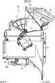
- FIG. 1 illustrates a blower unit 10 to which a fan attachment structure according to an embodiment of the present invention is applied.
- This blower unit 10 forms part of a vehicle air conditioner (not shown) installed in an automobile, for example.
- the vehicle air conditioner includes an air-conditioning unit (not shown) with a cooling heat exchanger and a heating heat exchanger, as well as the blower unit 10.
- the blower unit 10 is configured to supply air-conditioning air to the air-conditioning unit.
- the air-conditioning unit is configured to adjust the temperature of the air-conditioning air supplied from the blower unit 10 and then supply the air to respective parts of the vehicle cabin.
- the blower unit 10 and the air-conditioning unit are installed inside an instrument panel (not shown) arranged at a frontend of the vehicle cabin.
- the present invention will be described as being applied to a so-called “semi-center unit” in which the air-conditioning unit of the vehicle air conditioner is arranged around a center in the vehicle width direction and the blower unit 10 is arranged on the passenger seat side.
- the present invention is applicable to not only such a “semi-center unit” but also a “full-center unit” in which the heat exchangers and the blower fan are aggregated around the center in the vehicle width direction. Substantially the same fan attachment structure is applicable to these semi-center and full-center units.
- the blower unit 10 is designed for a left-hand drive vehicle, of which the passenger seat is provided on the right side thereof, and therefore, is arranged on the right side of the vehicle.
- front side of the vehicle will be hereinafter simply referred to as "front,” the rear side thereof “rear,” the left side thereof “left,” and the right side thereof “right.”
- the blower unit 10 includes a blower casing 11, a blower fan 12 housed in the blower casing 11, and a fan drive motor 13 to drive the blower fan 12.
- the blower casing 11 is comprised of a plurality of resin parts separable in the horizontal direction.
- a fan housing 14 in which the blower fan 12 is housed.
- an air outflow passage R is defined to surround the blower fan 12.
- a fresh/recirculation air switching portion 15 Over the blower casing 10, provided is a fresh/recirculation air switching portion 15.
- a fresh air inlet 16 is open at the frontend of the fresh/recirculation air switching portion 15. Although not shown, the fresh air inlet 16 communicates with the exterior of the vehicle cabin through a fresh-air-introducing duct.
- a recirculation air inlet 17 is open at the rear end of the fresh/recirculation air switching portion 15, and communicates with the interior of the vehicle cabin.
- a fresh/recirculation air switching damper is provided inside the fresh/recirculation air switching portion 15. The fresh/recirculation air switching damper allows the user to open one of the fresh and recirculation air inlets 16 and 17 and close the other.
- the fan housing 14 has a cylindrical shape as a whole.
- a duct portion 14a is provided for a left wall portion at the frontend of the fan housing 14.
- the duct portion 14a forms a downstream end portion of the air outflow passage R and is connected to the air-conditioning unit.
- the bottom wall portion of the fan housing 14 has an insertion hole (not shown) through which the blower fan 12 is inserted into the fan housing 14 while being mounted to this blower unit 10.
- This insertion hole is closed with a circular plate 20, which is attachable to, and removable from, the bottom wall portion of the fan housing 14.
- the circular plate 20 is provided with a fan drive motor 13, which may have a conventional known structure. As shown in FIG. 2 , the body portion of the fan drive motor 13 is provided so as to protrude both upward and downward with respect to the circular plate 20.
- the output shaft 13a of the fan drive motor 13 protrudes upward from the body of the fan drive motor 13.
- This output shaft 13a is arranged approximately at the center inside the fan housing 14.
- the output shaft 13a is implemented as a metallic round bar and has a generally circular cross section throughout the portion thereof that protrudes upward from the body of the fan drive motor 13.
- the blower fan 12 is a centrifugal fan (sirocco fan), and is configured to blow out the air sucked from over the blower fan 12 into the air outflow passage R of the fan housing 14 through the periphery of the blower fan 12.
- the blower fan 12 includes a fan body 25 and an anti-slip member 26.
- the fan body 25 may be an injection molded product of a resin material such as polypropylene, and includes a conic portion 27, a central cylindrical portion 28 provided at the center of the conic portion 27 (i.e., the center of rotation), and a large number of impellers 29, 29, ....
- the conic portion 27, central cylindrical portion 28, and impellers 29 have been molded integrally.
- the conic portion 27 of the fan body 25 has a curved shape overall such that a portion thereof around the center of rotation of the fan body 25 is located at the top and that the other portion thereof slopes radially downward and outward from the center of rotation toward the outer peripheral edge thereof.
- the radially outer peripheral portion of the conic portion 27 is located in the vicinity of the upper surface of the circular plate 20, and extends radially to define an annular extended portion 27a that runs continuously in the circumferential direction.
- the central cylindrical portion 28 of the fan body 25 extends vertically upward and downward, and has openings at the top and bottom thereof.
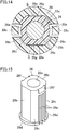
- the inner peripheral surface of the central cylindrical portion 28 has two fan's flat surfaces 28a, 28a and two fan's circular arc surfaces 28b, 28b, which are arranged alternately along the circumference of the central cylindrical portion 28.
- the fan's flat surfaces 28a, 28a extend along the centerline of the central cylindrical portion 28 and are arranged so as to radially face each other.
- the radial distance from one fan's flat surface 28a to the centerline of the central cylindrical portion 28 is equal to the radial distance from the other fan's flat surface 28a to the centerline of the central cylindrical portion 28.
- the fan's circular arc surfaces 28b, 28b have a circular arc shape, of which the center agrees with the centerline of the central cylindrical portion 28, and are arranged so as to face each other.
- the central cylindrical portion 28 of the fan body 25 there are two flexible pieces 28c, 28c, which are located at the fan's circular arc surfaces 28b, 28b of the central cylindrical portion 28.
- the flexible pieces 28c are made of a flexible resin material and are flexibly deformable overall such that their upper end portion is radially displaceable with respect to the central cylindrical portion 28.
- a clamping fitting A to clamp the central cylindrical portion 28 is provided over the central cylindrical portion 28.
- the impellers 29 have been molded to form integral parts of the upper surface of the annular extended portion 27a and to extend upward from the upper surface. Between each pair of impellers 29, a gap is left to allow the air to flow therethrough. At the top of the impellers 29, provided is an annular coupling portion 29a extending in the circumferential direction. The top of every impeller 29, 29, ... is connected to the coupling portion 29a.
- the anti-slip member 26 is formed by molding a resin material having higher mechanical strength (such as tensile strength or flexural strength) than the resin material of the fan body 25 into a cylindrical shape.
- the anti-slip member 26 is secured to the fan body 25 so as to be inserted into the central cylindrical portion 28 of the fan body 25.
- the center of the anti-slip member 26 is a shaft hole 26a to which the output shaft 13a of the motor 13 is fitted.
- the inner diameter of the shaft hole 26a is set to be a little smaller than the outer diameter of the output shaft 13a of the motor 13.
- the output shaft 13a of the motor 13 is fitted into the shaft hole 26a of the anti-slip member 26 with such contact force as to prevent the output shaft 13a from slipping in the rotational direction with respect to the anti-slip member 26 when the motor 13 is started up with the output shaft 13a fitted into the shaft hole 26a.
- This fitting slightly increases the outer diameter of the anti-slip member 26.
- the anti-slip member 26 is made of a resin material with high mechanical strength, and therefore, the output shaft 13a fitted into the shaft hole 26a of the anti-slip member 26 may be prevented for a long period of time from slipping in the rotational direction.
- not the entire blower fan 12 but only the anti-slip member 26 is molded out of a resin material with high mechanical strength. This may cut down the material cost of the blower fan 12.
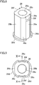
- the outer peripheral surface of a portion of the anti-slip member 26 to be inserted into the central cylindrical portion 28 have two shaft's flat surfaces 26b, 26b and two shaft's circular arc surfaces 26c, 26c, which are arranged alternately in the circumferential direction.
- the shaft's flat surfaces 26b, 26b extend along the centerline of the anti-slip member 26.
- the anti-slip member 26 is inserted into the central cylindrical portion 28 of the fan body 25 such that the shaft's flat surfaces 26b, 26b respectively face their associated fan's flat surfaces 28a, 28a and that the shaft's circular arc surfaces 26c, 26c respectively contact with their associated fan's circular arc surfaces 28b, 28b.
- Providing the shaft's flat surfaces 26b, 26b for the anti-slip member 26 may prevent the anti-slip member 26 from rotating relative to the central cylindrical portion 28 of the fan body 25.
- the shaft's flat surfaces 26b, 26b are arranged to be out of contact with their associated fan's flat surfaces 28a, 28a such that a gap S is left between each pair of shaft's and fan's flat surfaces 26b, 28a that face each other.
- the magnitude of the gap S between each pair of shaft's and fan's flat surfaces 26b, 28a is determined in advance so as not to go zero even when the anti-slip member 26 has its diameter increased by fitting the output shaft 13a of the motor 13 into the shaft hole 26a of the anti-slip member 26.
- flanges 26d, 26d are provided at the respective bottoms of the shaft's circular arc surfaces 26c, 26c of the anti-slip member 26. Each of these flanges 26d is provided to protrude radially outward from the range where its associated shaft's circular arc surface 26c is located. These flanges 26d are designed to abut with the bottom of the central cylindrical portion 28 of the fan body 25 when the anti-slip member 26 is inserted into the central cylindrical portion 28. This prevents the anti-slip member 26 from being accidentally drawn out upward from the central cylindrical portion 28.
- each recess 26e is formed on each shaft's circular arc surface 26c of the anti-slip member 26.
- each recess 26e has the shape of a rectangle extending upward from the bottom of its associated shaft's circular arc surface 26c.
- the top of each recess 26e is located under, and away from, the top of its associated shaft's circular arc surface 26c.
- each recess 26e is located at the middle of its associated shaft's circular arc surface 26c in the circumferential direction.
- each shaft's circular arc surface 26c of the anti-slip member 26 also has a sloped surface 26f which is located over its associated recess 26e.
- the sloped surface 26f is sloped such that the closer to the top, the closer to the centerline of the anti-slip member 26.
- the inner peripheral surface of the central cylindrical portion 28 of the fan body 25 has fan's flat surfaces 28a, 28a and fan's circular arc surfaces 28b, 28b
- the outer peripheral surface of the anti-slip member 26 has shaft's flat surfaces 26b, 26b extending along the fan's flat surfaces 28a, 28a and shaft's circular arc surfaces 26c, 26c extending along the fan's circular arc surfaces 28b, 28b. This significantly reduces the relative rotations between the anti-slip member 26 and the fan body 25.
- the motor 13 when the motor 13 is started up with its output shaft 13a fitted into the anti-slip member 26 that has been inserted into the central cylindrical portion 28 of the fan body 25, the rotational force of the output shaft 13a is transmitted to the fan body 25 via the anti-slip member 26, thus rotating the fan body 25.
- the recesses 26e, 26e formed on the outer peripheral surface of the anti-slip member 26 reduce the contact force between the outer peripheral surface of the anti-slip member 26 and the inner peripheral surface of the central cylindrical portion 28 of the fan body 25, even when the output shaft 13a is fitted thereto. This reduces the vibrations propagated from the motor 13 to the fan body 25 via the output shaft 13a and the anti-slip member 26, thus resulting in a significantly reduced harsh noise.
- the recesses 26e, 26e of the anti-slip member 26 extend along the centerline of the anti-slip member 26.
- the contact force produced by the outer peripheral surface of the anti-slip member 26 with respect to the inner peripheral surface of the central cylindrical portion 28 of the fan body 25 may be reduced in a broad range along the centerline of the anti-slip member 26. This further reduces the vibrations propagated to the fan body 25.
- the gap S left between each shaft's flat surface 26b of the anti-slip member 26 and its associated fan's flat surface 28a of the fan body 25 reduces the contact force produced by the outer peripheral surface of the anti-slip member 26 with respect to the inner peripheral surface of the central cylindrical portion 28 of the fan body 25, even after the output shaft 13a has been fitted. This reduces the vibrations propagated from the motor 13 to the fan body 25 via the output shaft 13a and the anti-slip member 26, thus resulting in a significantly reduced harsh noise.
- the gap S is supposed to be left between each shaft's flat surface 26b of the anti-slip member 26 and its associated fan's flat surface 28a of the fan body 25.
- the gap S may be eliminated, for example.
- each shaft's flat surface 26b of the anti-slip member 26 contacts with its associated fan's flat surface 28a of the fan body 25.
- the recesses 26e, 26e on the outer peripheral surface of the anti-slip member 26 may also reduce the contact force produced by the outer peripheral surface of the anti-slip member 26 with respect to the inner peripheral surface of the central cylindrical portion 28 of the fan body 25, even after the output shaft 13a has been fitted.
- the anti-slip member 26 has the shaft's flat surfaces 26b.
- the anti-slip member 26 may also have a pair of shaft's curved surfaces 26g.
- Each of these shaft's curved surfaces 26g is curved away from its associated fan's flat surface 28a of the fan body 25 (i.e., toward the output shaft 13a), thus leaving a gap S between the shaft's curved surface 26b and the fan's flat surface 28a.
- each fan's flat surface 28a may be replaced with a curved surface which is curved away from the output shaft 13a.
- each shaft's circular arc surface 26c of the anti-slip member 26 may have a plurality of recesses 26e.
- the recess 26e does not have to have a vertically elongated shape but may also have any other arbitrary shape.
- a fan attachment structure according to the present invention is applicable to a blower unit for a vehicle air conditioner, for example.
Landscapes
- Engineering & Computer Science (AREA)
- Mechanical Engineering (AREA)
- General Engineering & Computer Science (AREA)
- Physics & Mathematics (AREA)
- Thermal Sciences (AREA)
- Structures Of Non-Positive Displacement Pumps (AREA)
- Air-Conditioning For Vehicles (AREA)
Applications Claiming Priority (2)
| Application Number | Priority Date | Filing Date | Title |
|---|---|---|---|
| JP2014137426A JP6366389B2 (ja) | 2014-07-03 | 2014-07-03 | ファンの取付構造 |
| PCT/JP2015/002982 WO2016002142A1 (fr) | 2014-07-03 | 2015-06-15 | Structure de fixation de ventilateur |
Publications (3)
| Publication Number | Publication Date |
|---|---|
| EP3159548A1 true EP3159548A1 (fr) | 2017-04-26 |
| EP3159548A4 EP3159548A4 (fr) | 2017-08-16 |
| EP3159548B1 EP3159548B1 (fr) | 2020-08-05 |
Family
ID=55018723
Family Applications (1)
| Application Number | Title | Priority Date | Filing Date |
|---|---|---|---|
| EP15815221.5A Active EP3159548B1 (fr) | 2014-07-03 | 2015-06-15 | Ventilateur motorisé avec structure de fixation du ventilateur |
Country Status (5)
| Country | Link |
|---|---|
| US (1) | US10415583B2 (fr) |
| EP (1) | EP3159548B1 (fr) |
| JP (1) | JP6366389B2 (fr) |
| CN (1) | CN106460866B (fr) |
| WO (1) | WO2016002142A1 (fr) |
Families Citing this family (11)
| Publication number | Priority date | Publication date | Assignee | Title |
|---|---|---|---|---|
| JP6340281B2 (ja) * | 2014-08-04 | 2018-06-06 | 株式会社日本クライメイトシステムズ | ファンの取付構造 |
| CN205714976U (zh) * | 2016-03-07 | 2016-11-23 | 德昌电机(深圳)有限公司 | 风扇装置、电机及液泵 |
| EP3428455A4 (fr) * | 2016-03-08 | 2019-11-13 | Valeo Japan Co., Ltd. | Soufflante |
| WO2018075635A1 (fr) | 2016-10-18 | 2018-04-26 | Carrier Corporation | Souffleur courbé vers l'arrière à double entrée asymétrique |
| US20180170146A1 (en) * | 2016-12-16 | 2018-06-21 | Air International (Us) Inc. | Hvac system |
| US11041502B2 (en) | 2018-01-30 | 2021-06-22 | Carrier Corporation | Double inlet backward curved blower |
| JP2019157656A (ja) * | 2018-03-08 | 2019-09-19 | 日本電産株式会社 | 遠心ファン |
| CN114450491B (zh) * | 2019-10-17 | 2024-11-29 | 大金工业株式会社 | 送风机 |
| CN115540201B (zh) * | 2022-08-26 | 2025-03-21 | 青岛海尔空调器有限总公司 | 用于壁挂式空调器的检测方法及装置、空调器、存储介质 |
| USD999901S1 (en) * | 2023-02-03 | 2023-09-26 | Minhua Chen | Fan blade |
| CN117685240A (zh) * | 2023-12-11 | 2024-03-12 | 嘉善卡固电气设备股份有限公司 | 一种高防护等级的外转子离心风机 |
Family Cites Families (17)
| Publication number | Priority date | Publication date | Assignee | Title |
|---|---|---|---|---|
| US2882077A (en) * | 1954-02-01 | 1959-04-14 | Gen Ind Co | Molded plastic rotor hub tightening and driving construction |
| US2974502A (en) * | 1959-07-09 | 1961-03-14 | Westinghouse Electric Corp | Resilient mounting of fan on shaft |
| US3307634A (en) * | 1966-01-17 | 1967-03-07 | Otto L Bihlmire | Hub construction for boat propellers |
| DE2720408A1 (de) * | 1977-05-06 | 1978-10-26 | Christian Simon | Einsatzbuchse fuer fluegelluefterbohrungen |
| JPS6237626U (fr) * | 1985-08-23 | 1987-03-05 | ||
| JPH0176595U (fr) * | 1987-11-11 | 1989-05-24 | ||
| US4943209A (en) * | 1988-07-11 | 1990-07-24 | Heil-Quaker Corporation | Hub for a plastic blower impeller |
| US5399070A (en) * | 1992-07-22 | 1995-03-21 | Valeo Thermique Moteur | Fan hub |
| JPH11343997A (ja) * | 1998-05-29 | 1999-12-14 | Denso Corp | 送風機 |
| AUPQ475599A0 (en) * | 1999-12-17 | 2000-01-20 | Unisearch Limited | Inhibition of two-component transduction systems |
| US6890159B2 (en) * | 2002-03-19 | 2005-05-10 | Denso Corporation | Air blower with fan unable to contact motor housing |
| JP3804613B2 (ja) * | 2003-01-20 | 2006-08-02 | 株式会社デンソー | 送風機 |
| JP4385679B2 (ja) * | 2003-08-06 | 2009-12-16 | 株式会社デンソー | 送風機 |
| JP5229249B2 (ja) * | 2010-02-11 | 2013-07-03 | 株式会社デンソー | 送風機 |
| DE102011086379A1 (de) * | 2011-11-15 | 2013-05-16 | Robert Bosch Gmbh | Gebläsemodul für ein Kraftfahrzeug, Klimatisierungseinrichtung |
| CN202789665U (zh) * | 2012-07-31 | 2013-03-13 | 中山大洋电机制造有限公司 | 一种风机风轮与电机转轴连接结构 |
| CN203384096U (zh) * | 2013-08-06 | 2014-01-08 | 浙江三工汽车零部件有限公司 | 汽车水泵 |
-
2014
- 2014-07-03 JP JP2014137426A patent/JP6366389B2/ja active Active
-
2015
- 2015-06-15 EP EP15815221.5A patent/EP3159548B1/fr active Active
- 2015-06-15 CN CN201580033289.XA patent/CN106460866B/zh active Active
- 2015-06-15 WO PCT/JP2015/002982 patent/WO2016002142A1/fr not_active Ceased
-
2016
- 2016-12-29 US US15/394,093 patent/US10415583B2/en active Active
Also Published As
| Publication number | Publication date |
|---|---|
| JP2016014365A (ja) | 2016-01-28 |
| US10415583B2 (en) | 2019-09-17 |
| CN106460866A (zh) | 2017-02-22 |
| WO2016002142A1 (fr) | 2016-01-07 |
| EP3159548B1 (fr) | 2020-08-05 |
| CN106460866B (zh) | 2019-05-03 |
| JP6366389B2 (ja) | 2018-08-01 |
| US20170107997A1 (en) | 2017-04-20 |
| EP3159548A4 (fr) | 2017-08-16 |
Similar Documents
| Publication | Publication Date | Title |
|---|---|---|
| EP3159548B1 (fr) | Ventilateur motorisé avec structure de fixation du ventilateur | |
| US6789999B2 (en) | Center console dual centrifugal fan blower | |
| KR101985987B1 (ko) | 모터가 냉각되는 충격-흡수 팬 모터 유닛 | |
| CN101509496B (zh) | 电动鼓风机 | |
| CN212803748U (zh) | 送风装置和衣服 | |
| US20140341748A1 (en) | Axial-flow fan | |
| US11125249B2 (en) | Cooling fan apparatus | |
| JP2016191310A (ja) | インペラおよび送風機 | |
| US10288085B2 (en) | Centrifugal blower | |
| KR20120139727A (ko) | 원심 송풍기 조립체 | |
| EP3109484A1 (fr) | Dispositif de soufflage d'air | |
| US20150192131A1 (en) | Suppression of blade passing frequency tone in automotive air handling system | |
| US10436222B2 (en) | Fan attachment structure | |
| US10215188B2 (en) | Blower | |
| US9789748B2 (en) | Heating, ventilation and/or air-conditioning unit casing for motor vehicle passenger compartment | |
| US10605268B2 (en) | Blower | |
| WO2016006220A1 (fr) | Dispositif de commutation de canal d'air | |
| JP6396701B2 (ja) | ファンの取付構造 | |
| CN104321212B (zh) | 用于机动车辆乘客舱的供暖、通风和/或空调装备和用于所述装备的进气罩的元件 | |
| US11135901B2 (en) | Air vent structure | |
| CN207795689U (zh) | 可转向式离心风扇 | |
| SE0801123L (sv) | Kylsystem för ett motorfordon | |
| JP6909069B2 (ja) | 車両用空調装置の送風機 | |
| JP2015145198A (ja) | リアクーラ | |
| JP2018043588A (ja) | 空気通路開閉構造 |
Legal Events
| Date | Code | Title | Description |
|---|---|---|---|
| STAA | Information on the status of an ep patent application or granted ep patent |
Free format text: STATUS: THE INTERNATIONAL PUBLICATION HAS BEEN MADE |
|
| PUAI | Public reference made under article 153(3) epc to a published international application that has entered the european phase |
Free format text: ORIGINAL CODE: 0009012 |
|
| STAA | Information on the status of an ep patent application or granted ep patent |
Free format text: STATUS: REQUEST FOR EXAMINATION WAS MADE |
|
| 17P | Request for examination filed |
Effective date: 20161230 |
|
| AK | Designated contracting states |
Kind code of ref document: A1 Designated state(s): AL AT BE BG CH CY CZ DE DK EE ES FI FR GB GR HR HU IE IS IT LI LT LU LV MC MK MT NL NO PL PT RO RS SE SI SK SM TR |
|
| AX | Request for extension of the european patent |
Extension state: BA ME |
|
| A4 | Supplementary search report drawn up and despatched |
Effective date: 20170713 |
|
| RIC1 | Information provided on ipc code assigned before grant |
Ipc: F04D 29/62 20060101ALI20170707BHEP Ipc: F04D 29/28 20060101AFI20170707BHEP Ipc: B60H 1/00 20060101ALI20170707BHEP |
|
| DAV | Request for validation of the european patent (deleted) | ||
| DAX | Request for extension of the european patent (deleted) | ||
| GRAP | Despatch of communication of intention to grant a patent |
Free format text: ORIGINAL CODE: EPIDOSNIGR1 |
|
| STAA | Information on the status of an ep patent application or granted ep patent |
Free format text: STATUS: GRANT OF PATENT IS INTENDED |
|
| INTG | Intention to grant announced |
Effective date: 20200224 |
|
| GRAJ | Information related to disapproval of communication of intention to grant by the applicant or resumption of examination proceedings by the epo deleted |
Free format text: ORIGINAL CODE: EPIDOSDIGR1 |
|
| GRAS | Grant fee paid |
Free format text: ORIGINAL CODE: EPIDOSNIGR3 |
|
| GRAA | (expected) grant |
Free format text: ORIGINAL CODE: 0009210 |
|
| STAA | Information on the status of an ep patent application or granted ep patent |
Free format text: STATUS: THE PATENT HAS BEEN GRANTED |
|
| INTG | Intention to grant announced |
Effective date: 20200224 |
|
| AK | Designated contracting states |
Kind code of ref document: B1 Designated state(s): AL AT BE BG CH CY CZ DE DK EE ES FI FR GB GR HR HU IE IS IT LI LT LU LV MC MK MT NL NO PL PT RO RS SE SI SK SM TR |
|
| REG | Reference to a national code |
Ref country code: GB Ref legal event code: FG4D |
|
| REG | Reference to a national code |
Ref country code: CH Ref legal event code: EP |
|
| REG | Reference to a national code |
Ref country code: AT Ref legal event code: REF Ref document number: 1299085 Country of ref document: AT Kind code of ref document: T Effective date: 20200815 |
|
| REG | Reference to a national code |
Ref country code: DE Ref legal event code: R096 Ref document number: 602015057072 Country of ref document: DE |
|
| REG | Reference to a national code |
Ref country code: IE Ref legal event code: FG4D |
|
| REG | Reference to a national code |
Ref country code: LT Ref legal event code: MG4D |
|
| REG | Reference to a national code |
Ref country code: NL Ref legal event code: MP Effective date: 20200805 |
|
| REG | Reference to a national code |
Ref country code: AT Ref legal event code: MK05 Ref document number: 1299085 Country of ref document: AT Kind code of ref document: T Effective date: 20200805 |
|
| PG25 | Lapsed in a contracting state [announced via postgrant information from national office to epo] |
Ref country code: LT Free format text: LAPSE BECAUSE OF FAILURE TO SUBMIT A TRANSLATION OF THE DESCRIPTION OR TO PAY THE FEE WITHIN THE PRESCRIBED TIME-LIMIT Effective date: 20200805 Ref country code: HR Free format text: LAPSE BECAUSE OF FAILURE TO SUBMIT A TRANSLATION OF THE DESCRIPTION OR TO PAY THE FEE WITHIN THE PRESCRIBED TIME-LIMIT Effective date: 20200805 Ref country code: SE Free format text: LAPSE BECAUSE OF FAILURE TO SUBMIT A TRANSLATION OF THE DESCRIPTION OR TO PAY THE FEE WITHIN THE PRESCRIBED TIME-LIMIT Effective date: 20200805 Ref country code: BG Free format text: LAPSE BECAUSE OF FAILURE TO SUBMIT A TRANSLATION OF THE DESCRIPTION OR TO PAY THE FEE WITHIN THE PRESCRIBED TIME-LIMIT Effective date: 20201105 Ref country code: PT Free format text: LAPSE BECAUSE OF FAILURE TO SUBMIT A TRANSLATION OF THE DESCRIPTION OR TO PAY THE FEE WITHIN THE PRESCRIBED TIME-LIMIT Effective date: 20201207 Ref country code: ES Free format text: LAPSE BECAUSE OF FAILURE TO SUBMIT A TRANSLATION OF THE DESCRIPTION OR TO PAY THE FEE WITHIN THE PRESCRIBED TIME-LIMIT Effective date: 20200805 Ref country code: NO Free format text: LAPSE BECAUSE OF FAILURE TO SUBMIT A TRANSLATION OF THE DESCRIPTION OR TO PAY THE FEE WITHIN THE PRESCRIBED TIME-LIMIT Effective date: 20201105 Ref country code: GR Free format text: LAPSE BECAUSE OF FAILURE TO SUBMIT A TRANSLATION OF THE DESCRIPTION OR TO PAY THE FEE WITHIN THE PRESCRIBED TIME-LIMIT Effective date: 20201106 Ref country code: FI Free format text: LAPSE BECAUSE OF FAILURE TO SUBMIT A TRANSLATION OF THE DESCRIPTION OR TO PAY THE FEE WITHIN THE PRESCRIBED TIME-LIMIT Effective date: 20200805 Ref country code: AT Free format text: LAPSE BECAUSE OF FAILURE TO SUBMIT A TRANSLATION OF THE DESCRIPTION OR TO PAY THE FEE WITHIN THE PRESCRIBED TIME-LIMIT Effective date: 20200805 |
|
| PG25 | Lapsed in a contracting state [announced via postgrant information from national office to epo] |
Ref country code: RS Free format text: LAPSE BECAUSE OF FAILURE TO SUBMIT A TRANSLATION OF THE DESCRIPTION OR TO PAY THE FEE WITHIN THE PRESCRIBED TIME-LIMIT Effective date: 20200805 Ref country code: LV Free format text: LAPSE BECAUSE OF FAILURE TO SUBMIT A TRANSLATION OF THE DESCRIPTION OR TO PAY THE FEE WITHIN THE PRESCRIBED TIME-LIMIT Effective date: 20200805 Ref country code: NL Free format text: LAPSE BECAUSE OF FAILURE TO SUBMIT A TRANSLATION OF THE DESCRIPTION OR TO PAY THE FEE WITHIN THE PRESCRIBED TIME-LIMIT Effective date: 20200805 Ref country code: PL Free format text: LAPSE BECAUSE OF FAILURE TO SUBMIT A TRANSLATION OF THE DESCRIPTION OR TO PAY THE FEE WITHIN THE PRESCRIBED TIME-LIMIT Effective date: 20200805 Ref country code: IS Free format text: LAPSE BECAUSE OF FAILURE TO SUBMIT A TRANSLATION OF THE DESCRIPTION OR TO PAY THE FEE WITHIN THE PRESCRIBED TIME-LIMIT Effective date: 20201205 |
|
| PG25 | Lapsed in a contracting state [announced via postgrant information from national office to epo] |
Ref country code: DK Free format text: LAPSE BECAUSE OF FAILURE TO SUBMIT A TRANSLATION OF THE DESCRIPTION OR TO PAY THE FEE WITHIN THE PRESCRIBED TIME-LIMIT Effective date: 20200805 Ref country code: CZ Free format text: LAPSE BECAUSE OF FAILURE TO SUBMIT A TRANSLATION OF THE DESCRIPTION OR TO PAY THE FEE WITHIN THE PRESCRIBED TIME-LIMIT Effective date: 20200805 Ref country code: EE Free format text: LAPSE BECAUSE OF FAILURE TO SUBMIT A TRANSLATION OF THE DESCRIPTION OR TO PAY THE FEE WITHIN THE PRESCRIBED TIME-LIMIT Effective date: 20200805 Ref country code: SM Free format text: LAPSE BECAUSE OF FAILURE TO SUBMIT A TRANSLATION OF THE DESCRIPTION OR TO PAY THE FEE WITHIN THE PRESCRIBED TIME-LIMIT Effective date: 20200805 Ref country code: RO Free format text: LAPSE BECAUSE OF FAILURE TO SUBMIT A TRANSLATION OF THE DESCRIPTION OR TO PAY THE FEE WITHIN THE PRESCRIBED TIME-LIMIT Effective date: 20200805 |
|
| REG | Reference to a national code |
Ref country code: DE Ref legal event code: R097 Ref document number: 602015057072 Country of ref document: DE |
|
| PG25 | Lapsed in a contracting state [announced via postgrant information from national office to epo] |
Ref country code: AL Free format text: LAPSE BECAUSE OF FAILURE TO SUBMIT A TRANSLATION OF THE DESCRIPTION OR TO PAY THE FEE WITHIN THE PRESCRIBED TIME-LIMIT Effective date: 20200805 |
|
| PLBE | No opposition filed within time limit |
Free format text: ORIGINAL CODE: 0009261 |
|
| STAA | Information on the status of an ep patent application or granted ep patent |
Free format text: STATUS: NO OPPOSITION FILED WITHIN TIME LIMIT |
|
| PG25 | Lapsed in a contracting state [announced via postgrant information from national office to epo] |
Ref country code: SK Free format text: LAPSE BECAUSE OF FAILURE TO SUBMIT A TRANSLATION OF THE DESCRIPTION OR TO PAY THE FEE WITHIN THE PRESCRIBED TIME-LIMIT Effective date: 20200805 |
|
| 26N | No opposition filed |
Effective date: 20210507 |
|
| PG25 | Lapsed in a contracting state [announced via postgrant information from national office to epo] |
Ref country code: IT Free format text: LAPSE BECAUSE OF FAILURE TO SUBMIT A TRANSLATION OF THE DESCRIPTION OR TO PAY THE FEE WITHIN THE PRESCRIBED TIME-LIMIT Effective date: 20200805 |
|
| PG25 | Lapsed in a contracting state [announced via postgrant information from national office to epo] |
Ref country code: SI Free format text: LAPSE BECAUSE OF FAILURE TO SUBMIT A TRANSLATION OF THE DESCRIPTION OR TO PAY THE FEE WITHIN THE PRESCRIBED TIME-LIMIT Effective date: 20200805 |
|
| PG25 | Lapsed in a contracting state [announced via postgrant information from national office to epo] |
Ref country code: MC Free format text: LAPSE BECAUSE OF FAILURE TO SUBMIT A TRANSLATION OF THE DESCRIPTION OR TO PAY THE FEE WITHIN THE PRESCRIBED TIME-LIMIT Effective date: 20200805 |
|
| REG | Reference to a national code |
Ref country code: CH Ref legal event code: PL |
|
| GBPC | Gb: european patent ceased through non-payment of renewal fee |
Effective date: 20210615 |
|
| REG | Reference to a national code |
Ref country code: BE Ref legal event code: MM Effective date: 20210630 |
|
| PG25 | Lapsed in a contracting state [announced via postgrant information from national office to epo] |
Ref country code: LU Free format text: LAPSE BECAUSE OF NON-PAYMENT OF DUE FEES Effective date: 20210615 |
|
| PG25 | Lapsed in a contracting state [announced via postgrant information from national office to epo] |
Ref country code: LI Free format text: LAPSE BECAUSE OF NON-PAYMENT OF DUE FEES Effective date: 20210630 Ref country code: IE Free format text: LAPSE BECAUSE OF NON-PAYMENT OF DUE FEES Effective date: 20210615 Ref country code: GB Free format text: LAPSE BECAUSE OF NON-PAYMENT OF DUE FEES Effective date: 20210615 Ref country code: CH Free format text: LAPSE BECAUSE OF NON-PAYMENT OF DUE FEES Effective date: 20210630 |
|
| PG25 | Lapsed in a contracting state [announced via postgrant information from national office to epo] |
Ref country code: BE Free format text: LAPSE BECAUSE OF NON-PAYMENT OF DUE FEES Effective date: 20210630 |
|
| PG25 | Lapsed in a contracting state [announced via postgrant information from national office to epo] |
Ref country code: HU Free format text: LAPSE BECAUSE OF FAILURE TO SUBMIT A TRANSLATION OF THE DESCRIPTION OR TO PAY THE FEE WITHIN THE PRESCRIBED TIME-LIMIT; INVALID AB INITIO Effective date: 20150615 |
|
| PG25 | Lapsed in a contracting state [announced via postgrant information from national office to epo] |
Ref country code: CY Free format text: LAPSE BECAUSE OF FAILURE TO SUBMIT A TRANSLATION OF THE DESCRIPTION OR TO PAY THE FEE WITHIN THE PRESCRIBED TIME-LIMIT Effective date: 20200805 |
|
| PG25 | Lapsed in a contracting state [announced via postgrant information from national office to epo] |
Ref country code: MK Free format text: LAPSE BECAUSE OF FAILURE TO SUBMIT A TRANSLATION OF THE DESCRIPTION OR TO PAY THE FEE WITHIN THE PRESCRIBED TIME-LIMIT Effective date: 20200805 |
|
| PG25 | Lapsed in a contracting state [announced via postgrant information from national office to epo] |
Ref country code: MT Free format text: LAPSE BECAUSE OF FAILURE TO SUBMIT A TRANSLATION OF THE DESCRIPTION OR TO PAY THE FEE WITHIN THE PRESCRIBED TIME-LIMIT Effective date: 20200805 |
|
| PGFP | Annual fee paid to national office [announced via postgrant information from national office to epo] |
Ref country code: DE Payment date: 20250618 Year of fee payment: 11 |
|
| PGFP | Annual fee paid to national office [announced via postgrant information from national office to epo] |
Ref country code: FR Payment date: 20250625 Year of fee payment: 11 |
|
| PG25 | Lapsed in a contracting state [announced via postgrant information from national office to epo] |
Ref country code: TR Free format text: LAPSE BECAUSE OF FAILURE TO SUBMIT A TRANSLATION OF THE DESCRIPTION OR TO PAY THE FEE WITHIN THE PRESCRIBED TIME-LIMIT Effective date: 20200805 |