EP3159581B1 - Hydraulische steuerungsvorrichtung zur automatischen übertragung und steuerungsverfahren dafür - Google Patents
Hydraulische steuerungsvorrichtung zur automatischen übertragung und steuerungsverfahren dafür Download PDFInfo
- Publication number
- EP3159581B1 EP3159581B1 EP15809496.1A EP15809496A EP3159581B1 EP 3159581 B1 EP3159581 B1 EP 3159581B1 EP 15809496 A EP15809496 A EP 15809496A EP 3159581 B1 EP3159581 B1 EP 3159581B1
- Authority
- EP
- European Patent Office
- Prior art keywords
- accelerator pedal
- throttle valve
- valve opening
- tvo
- opening
- Prior art date
- Legal status (The legal status is an assumption and is not a legal conclusion. Google has not performed a legal analysis and makes no representation as to the accuracy of the status listed.)
- Not-in-force
Links
Images




Classifications
-
- F—MECHANICAL ENGINEERING; LIGHTING; HEATING; WEAPONS; BLASTING
- F16—ENGINEERING ELEMENTS AND UNITS; GENERAL MEASURES FOR PRODUCING AND MAINTAINING EFFECTIVE FUNCTIONING OF MACHINES OR INSTALLATIONS; THERMAL INSULATION IN GENERAL
- F16D—COUPLINGS FOR TRANSMITTING ROTATION; CLUTCHES; BRAKES
- F16D48/00—External control of clutches
- F16D48/06—Control by electric or electronic means, e.g. of fluid pressure
-
- F—MECHANICAL ENGINEERING; LIGHTING; HEATING; WEAPONS; BLASTING
- F16—ENGINEERING ELEMENTS AND UNITS; GENERAL MEASURES FOR PRODUCING AND MAINTAINING EFFECTIVE FUNCTIONING OF MACHINES OR INSTALLATIONS; THERMAL INSULATION IN GENERAL
- F16H—GEARING
- F16H61/00—Control functions within control units of change-speed- or reversing-gearings for conveying rotary motion ; Control of exclusively fluid gearing, friction gearing, gearings with endless flexible members or other particular types of gearing
- F16H61/02—Control functions within control units of change-speed- or reversing-gearings for conveying rotary motion ; Control of exclusively fluid gearing, friction gearing, gearings with endless flexible members or other particular types of gearing characterised by the signals used
- F16H61/0262—Control functions within control units of change-speed- or reversing-gearings for conveying rotary motion ; Control of exclusively fluid gearing, friction gearing, gearings with endless flexible members or other particular types of gearing characterised by the signals used the signals being hydraulic
-
- B—PERFORMING OPERATIONS; TRANSPORTING
- B60—VEHICLES IN GENERAL
- B60W—CONJOINT CONTROL OF VEHICLE SUB-UNITS OF DIFFERENT TYPE OR DIFFERENT FUNCTION; CONTROL SYSTEMS SPECIALLY ADAPTED FOR HYBRID VEHICLES; ROAD VEHICLE DRIVE CONTROL SYSTEMS FOR PURPOSES NOT RELATED TO THE CONTROL OF A PARTICULAR SUB-UNIT
- B60W10/00—Conjoint control of vehicle sub-units of different type or different function
- B60W10/04—Conjoint control of vehicle sub-units of different type or different function including control of propulsion units
- B60W10/06—Conjoint control of vehicle sub-units of different type or different function including control of propulsion units including control of combustion engines
-
- B—PERFORMING OPERATIONS; TRANSPORTING
- B60—VEHICLES IN GENERAL
- B60W—CONJOINT CONTROL OF VEHICLE SUB-UNITS OF DIFFERENT TYPE OR DIFFERENT FUNCTION; CONTROL SYSTEMS SPECIALLY ADAPTED FOR HYBRID VEHICLES; ROAD VEHICLE DRIVE CONTROL SYSTEMS FOR PURPOSES NOT RELATED TO THE CONTROL OF A PARTICULAR SUB-UNIT
- B60W10/00—Conjoint control of vehicle sub-units of different type or different function
- B60W10/10—Conjoint control of vehicle sub-units of different type or different function including control of change-speed gearings
- B60W10/11—Stepped gearings
- B60W10/115—Stepped gearings with planetary gears
-
- B—PERFORMING OPERATIONS; TRANSPORTING
- B60—VEHICLES IN GENERAL
- B60W—CONJOINT CONTROL OF VEHICLE SUB-UNITS OF DIFFERENT TYPE OR DIFFERENT FUNCTION; CONTROL SYSTEMS SPECIALLY ADAPTED FOR HYBRID VEHICLES; ROAD VEHICLE DRIVE CONTROL SYSTEMS FOR PURPOSES NOT RELATED TO THE CONTROL OF A PARTICULAR SUB-UNIT
- B60W10/00—Conjoint control of vehicle sub-units of different type or different function
- B60W10/18—Conjoint control of vehicle sub-units of different type or different function including control of braking systems
- B60W10/182—Conjoint control of vehicle sub-units of different type or different function including control of braking systems including control of parking brakes
-
- B—PERFORMING OPERATIONS; TRANSPORTING
- B60—VEHICLES IN GENERAL
- B60W—CONJOINT CONTROL OF VEHICLE SUB-UNITS OF DIFFERENT TYPE OR DIFFERENT FUNCTION; CONTROL SYSTEMS SPECIALLY ADAPTED FOR HYBRID VEHICLES; ROAD VEHICLE DRIVE CONTROL SYSTEMS FOR PURPOSES NOT RELATED TO THE CONTROL OF A PARTICULAR SUB-UNIT
- B60W30/00—Purposes of road vehicle drive control systems not related to the control of a particular sub-unit, e.g. of systems using conjoint control of vehicle sub-units
- B60W30/18—Propelling the vehicle
- B60W30/18009—Propelling the vehicle related to particular drive situations
- B60W30/18027—Drive off, accelerating from standstill
-
- F—MECHANICAL ENGINEERING; LIGHTING; HEATING; WEAPONS; BLASTING
- F16—ENGINEERING ELEMENTS AND UNITS; GENERAL MEASURES FOR PRODUCING AND MAINTAINING EFFECTIVE FUNCTIONING OF MACHINES OR INSTALLATIONS; THERMAL INSULATION IN GENERAL
- F16D—COUPLINGS FOR TRANSMITTING ROTATION; CLUTCHES; BRAKES
- F16D48/00—External control of clutches
- F16D48/02—Control by fluid pressure
-
- F—MECHANICAL ENGINEERING; LIGHTING; HEATING; WEAPONS; BLASTING
- F16—ENGINEERING ELEMENTS AND UNITS; GENERAL MEASURES FOR PRODUCING AND MAINTAINING EFFECTIVE FUNCTIONING OF MACHINES OR INSTALLATIONS; THERMAL INSULATION IN GENERAL
- F16D—COUPLINGS FOR TRANSMITTING ROTATION; CLUTCHES; BRAKES
- F16D48/00—External control of clutches
- F16D48/06—Control by electric or electronic means, e.g. of fluid pressure
- F16D48/066—Control of fluid pressure, e.g. using an accumulator
-
- F—MECHANICAL ENGINEERING; LIGHTING; HEATING; WEAPONS; BLASTING
- F16—ENGINEERING ELEMENTS AND UNITS; GENERAL MEASURES FOR PRODUCING AND MAINTAINING EFFECTIVE FUNCTIONING OF MACHINES OR INSTALLATIONS; THERMAL INSULATION IN GENERAL
- F16H—GEARING
- F16H61/00—Control functions within control units of change-speed- or reversing-gearings for conveying rotary motion ; Control of exclusively fluid gearing, friction gearing, gearings with endless flexible members or other particular types of gearing
- F16H61/04—Smoothing ratio shift
-
- F—MECHANICAL ENGINEERING; LIGHTING; HEATING; WEAPONS; BLASTING
- F16—ENGINEERING ELEMENTS AND UNITS; GENERAL MEASURES FOR PRODUCING AND MAINTAINING EFFECTIVE FUNCTIONING OF MACHINES OR INSTALLATIONS; THERMAL INSULATION IN GENERAL
- F16H—GEARING
- F16H61/00—Control functions within control units of change-speed- or reversing-gearings for conveying rotary motion ; Control of exclusively fluid gearing, friction gearing, gearings with endless flexible members or other particular types of gearing
- F16H61/04—Smoothing ratio shift
- F16H61/06—Smoothing ratio shift by controlling rate of change of fluid pressure
- F16H61/061—Smoothing ratio shift by controlling rate of change of fluid pressure using electric control means
-
- F—MECHANICAL ENGINEERING; LIGHTING; HEATING; WEAPONS; BLASTING
- F16—ENGINEERING ELEMENTS AND UNITS; GENERAL MEASURES FOR PRODUCING AND MAINTAINING EFFECTIVE FUNCTIONING OF MACHINES OR INSTALLATIONS; THERMAL INSULATION IN GENERAL
- F16H—GEARING
- F16H61/00—Control functions within control units of change-speed- or reversing-gearings for conveying rotary motion ; Control of exclusively fluid gearing, friction gearing, gearings with endless flexible members or other particular types of gearing
- F16H61/04—Smoothing ratio shift
- F16H61/08—Timing control
-
- F—MECHANICAL ENGINEERING; LIGHTING; HEATING; WEAPONS; BLASTING
- F16—ENGINEERING ELEMENTS AND UNITS; GENERAL MEASURES FOR PRODUCING AND MAINTAINING EFFECTIVE FUNCTIONING OF MACHINES OR INSTALLATIONS; THERMAL INSULATION IN GENERAL
- F16D—COUPLINGS FOR TRANSMITTING ROTATION; CLUTCHES; BRAKES
- F16D2500/00—External control of clutches by electric or electronic means
- F16D2500/30—Signal inputs
- F16D2500/314—Signal inputs from the user
- F16D2500/31406—Signal inputs from the user input from pedals
- F16D2500/3144—Accelerator pedal position
-
- F—MECHANICAL ENGINEERING; LIGHTING; HEATING; WEAPONS; BLASTING
- F16—ENGINEERING ELEMENTS AND UNITS; GENERAL MEASURES FOR PRODUCING AND MAINTAINING EFFECTIVE FUNCTIONING OF MACHINES OR INSTALLATIONS; THERMAL INSULATION IN GENERAL
- F16D—COUPLINGS FOR TRANSMITTING ROTATION; CLUTCHES; BRAKES
- F16D2500/00—External control of clutches by electric or electronic means
- F16D2500/30—Signal inputs
- F16D2500/314—Signal inputs from the user
- F16D2500/3146—Signal inputs from the user input from levers
- F16D2500/31466—Gear lever
-
- F—MECHANICAL ENGINEERING; LIGHTING; HEATING; WEAPONS; BLASTING
- F16—ENGINEERING ELEMENTS AND UNITS; GENERAL MEASURES FOR PRODUCING AND MAINTAINING EFFECTIVE FUNCTIONING OF MACHINES OR INSTALLATIONS; THERMAL INSULATION IN GENERAL
- F16D—COUPLINGS FOR TRANSMITTING ROTATION; CLUTCHES; BRAKES
- F16D2500/00—External control of clutches by electric or electronic means
- F16D2500/30—Signal inputs
- F16D2500/316—Other signal inputs not covered by the groups above
- F16D2500/3166—Detection of an elapsed period of time
-
- F—MECHANICAL ENGINEERING; LIGHTING; HEATING; WEAPONS; BLASTING
- F16—ENGINEERING ELEMENTS AND UNITS; GENERAL MEASURES FOR PRODUCING AND MAINTAINING EFFECTIVE FUNCTIONING OF MACHINES OR INSTALLATIONS; THERMAL INSULATION IN GENERAL
- F16D—COUPLINGS FOR TRANSMITTING ROTATION; CLUTCHES; BRAKES
- F16D2500/00—External control of clutches by electric or electronic means
- F16D2500/50—Problem to be solved by the control system
- F16D2500/502—Relating the clutch
- F16D2500/50206—Creep control
-
- F—MECHANICAL ENGINEERING; LIGHTING; HEATING; WEAPONS; BLASTING
- F16—ENGINEERING ELEMENTS AND UNITS; GENERAL MEASURES FOR PRODUCING AND MAINTAINING EFFECTIVE FUNCTIONING OF MACHINES OR INSTALLATIONS; THERMAL INSULATION IN GENERAL
- F16D—COUPLINGS FOR TRANSMITTING ROTATION; CLUTCHES; BRAKES
- F16D2500/00—External control of clutches by electric or electronic means
- F16D2500/50—Problem to be solved by the control system
- F16D2500/508—Relating driving conditions
- F16D2500/50866—Parking, i.e. control of drive units during parking
-
- F—MECHANICAL ENGINEERING; LIGHTING; HEATING; WEAPONS; BLASTING
- F16—ENGINEERING ELEMENTS AND UNITS; GENERAL MEASURES FOR PRODUCING AND MAINTAINING EFFECTIVE FUNCTIONING OF MACHINES OR INSTALLATIONS; THERMAL INSULATION IN GENERAL
- F16D—COUPLINGS FOR TRANSMITTING ROTATION; CLUTCHES; BRAKES
- F16D41/00—Freewheels or freewheel clutches
- F16D41/04—Freewheels or freewheel clutches combined with a clutch for locking the driving and driven members
-
- F—MECHANICAL ENGINEERING; LIGHTING; HEATING; WEAPONS; BLASTING
- F16—ENGINEERING ELEMENTS AND UNITS; GENERAL MEASURES FOR PRODUCING AND MAINTAINING EFFECTIVE FUNCTIONING OF MACHINES OR INSTALLATIONS; THERMAL INSULATION IN GENERAL
- F16H—GEARING
- F16H59/00—Control inputs to control units of change-speed- or reversing-gearings for conveying rotary motion
- F16H59/02—Selector apparatus
- F16H59/08—Range selector apparatus
- F16H2059/082—Range selector apparatus for different transmission modes
- F16H2059/088—Fast forward-reverse-sequence, e.g. rocking mode
-
- F—MECHANICAL ENGINEERING; LIGHTING; HEATING; WEAPONS; BLASTING
- F16—ENGINEERING ELEMENTS AND UNITS; GENERAL MEASURES FOR PRODUCING AND MAINTAINING EFFECTIVE FUNCTIONING OF MACHINES OR INSTALLATIONS; THERMAL INSULATION IN GENERAL
- F16H—GEARING
- F16H59/00—Control inputs to control units of change-speed- or reversing-gearings for conveying rotary motion
- F16H59/68—Inputs being a function of gearing status
- F16H2059/6807—Status of gear-change operation, e.g. clutch fully engaged
-
- F—MECHANICAL ENGINEERING; LIGHTING; HEATING; WEAPONS; BLASTING
- F16—ENGINEERING ELEMENTS AND UNITS; GENERAL MEASURES FOR PRODUCING AND MAINTAINING EFFECTIVE FUNCTIONING OF MACHINES OR INSTALLATIONS; THERMAL INSULATION IN GENERAL
- F16H—GEARING
- F16H61/00—Control functions within control units of change-speed- or reversing-gearings for conveying rotary motion ; Control of exclusively fluid gearing, friction gearing, gearings with endless flexible members or other particular types of gearing
- F16H61/04—Smoothing ratio shift
- F16H2061/0481—Smoothing ratio shift during range shift from drive (D) or reverse (R) to neutral (N)
-
- F—MECHANICAL ENGINEERING; LIGHTING; HEATING; WEAPONS; BLASTING
- F16—ENGINEERING ELEMENTS AND UNITS; GENERAL MEASURES FOR PRODUCING AND MAINTAINING EFFECTIVE FUNCTIONING OF MACHINES OR INSTALLATIONS; THERMAL INSULATION IN GENERAL
- F16H—GEARING
- F16H61/00—Control functions within control units of change-speed- or reversing-gearings for conveying rotary motion ; Control of exclusively fluid gearing, friction gearing, gearings with endless flexible members or other particular types of gearing
- F16H61/04—Smoothing ratio shift
- F16H2061/0485—Smoothing ratio shift during range shift from neutral (N) to reverse (R)
-
- F—MECHANICAL ENGINEERING; LIGHTING; HEATING; WEAPONS; BLASTING
- F16—ENGINEERING ELEMENTS AND UNITS; GENERAL MEASURES FOR PRODUCING AND MAINTAINING EFFECTIVE FUNCTIONING OF MACHINES OR INSTALLATIONS; THERMAL INSULATION IN GENERAL
- F16H—GEARING
- F16H59/00—Control inputs to control units of change-speed- or reversing-gearings for conveying rotary motion
- F16H59/02—Selector apparatus
- F16H59/08—Range selector apparatus
- F16H59/10—Range selector apparatus comprising levers
- F16H59/105—Range selector apparatus comprising levers consisting of electrical switches or sensors
-
- F—MECHANICAL ENGINEERING; LIGHTING; HEATING; WEAPONS; BLASTING
- F16—ENGINEERING ELEMENTS AND UNITS; GENERAL MEASURES FOR PRODUCING AND MAINTAINING EFFECTIVE FUNCTIONING OF MACHINES OR INSTALLATIONS; THERMAL INSULATION IN GENERAL
- F16H—GEARING
- F16H59/00—Control inputs to control units of change-speed- or reversing-gearings for conveying rotary motion
- F16H59/14—Inputs being a function of torque or torque demand
- F16H59/18—Inputs being a function of torque or torque demand dependent on the position of the accelerator pedal
-
- F—MECHANICAL ENGINEERING; LIGHTING; HEATING; WEAPONS; BLASTING
- F16—ENGINEERING ELEMENTS AND UNITS; GENERAL MEASURES FOR PRODUCING AND MAINTAINING EFFECTIVE FUNCTIONING OF MACHINES OR INSTALLATIONS; THERMAL INSULATION IN GENERAL
- F16H—GEARING
- F16H59/00—Control inputs to control units of change-speed- or reversing-gearings for conveying rotary motion
- F16H59/14—Inputs being a function of torque or torque demand
- F16H59/24—Inputs being a function of torque or torque demand dependent on the throttle opening
Definitions
- the present invention relates to a hydraulic control of an automatic transmission.
- a vehicle with an electronically controlled throttle device for changing a throttle valve opening by operating an electric actuator on the basis of an accelerator pedal opening is disclosed in JP2003-97659A .
- the throttle valve opening is detected by a throttle valve opening sensor, an input torque to the transmission is calculated on the basis of the throttle valve opening and a hydraulic pressure supplied to the friction engaging element is controlled on the basis of the input torque. That is, the hydraulic pressure supplied to the friction engaging element is controlled on the basis of the throttle valve opening.
- a method for increasing a climb gradient of the hydraulic pressure supplied to the friction engaging element is, for example, considered as a method for quickly engaging the friction engaging element.
- a method for controlling the hydraulic pressure supplied to the friction engaging element by reading a driver's intention to start on the basis of the behavior of the throttle valve opening is, for example, considered as the method for quickly engaging the friction engaging element.
- the present invention was developed in view of such a problem and aims to suppress an increase of an engagement shock and suppress the engagement of a friction engaging element at a timing different from a driver's intention to start at the time of a garage shift.
- a hydraulic control device for automatic transmission is a hydraulic control device for automatic transmission including an electronically controlled throttle device for changing a throttle valve opening of a prime mover by an electric actuator on the basis of an accelerator pedal opening and configured to supply a hydraulic pressure to a friction engaging element of a transmission on the basis of the throttle valve opening.
- the hydraulic control device includes accelerator pedal opening detection means configured to detect the accelerator pedal opening, throttle valve opening detection means configured to detect the throttle valve opening, shift lever positon detection means configured to detect a position of a shift lever, and hydraulic control means configured to control a start timing of a supply of the hydraulic pressure to the friction engaging element on the basis of the accelerator pedal opening and the throttle valve opening if the shift lever is changed from an advance position to a reverse position or from the reverse position to the advance position.
- a control method for a hydraulic control device is a control method for a hydraulic control device including an electronically controlled throttle device for changing a throttle valve opening of a prime mover by an electric actuator on the basis of an accelerator pedal opening and configured to supply a hydraulic pressure to a friction engaging element of a transmission on the basis of the throttle valve opening.
- the control method includes detecting the accelerator pedal opening, detecting the throttle valve opening, detecting a position of a shift lever, and controlling a start timing of a supply of the hydraulic pressure to the friction engaging element on the basis of the accelerator pedal opening and the throttle valve opening if the shift lever is changed from an advance position to a reverse position or from the reverse position to the advance position.
- the start timing of the supply of the hydraulic pressure to the friction engaging element is controlled on the basis of the accelerator pedal opening and the throttle valve opening when the shift lever is changed from the advance position to the reverse position or from the reverse position to the advance position.
- a "speed ratio" of a certain transmission mechanism is a value obtained by dividing an input rotation speed of this transmission mechanism by an output rotation speed thereof.
- FIG. 1 is a schematic configuration diagram of a vehicle according to the present embodiment.
- This vehicle includes an engine 1 as a drive source, and the output rotation of the engine 1 is transmitted to drive wheels 7 via a torque converter 2 with a lock-up clutch, a first gear train 3, a transmission 4, a second gear train 5 and a differential device 6.
- the vehicle includes an electronically controlled throttle device 50 in which an opening of a throttle valve 52 (hereinafter, referred to as a “throttle valve opening TVO") is controlled by a throttle actuator 51 configured to operate according to an operation amount of an accelerator pedal (hereinafter, referred to as an “accelerator pedal opening APO”) or the like.
- a throttle valve 52 hereinafter, referred to as a "throttle valve opening TVO”
- a throttle actuator 51 configured to operate according to an operation amount of an accelerator pedal (hereinafter, referred to as an “accelerator pedal opening APO”) or the like.
- the transmission 4 is provided with a mechanical oil pump 10m to which the rotation of the engine 1 is input and which is driven utilizing part of power of the engine 1. Further, the transmission 4 is provided with a hydraulic control circuit 11 for adjusting a hydraulic pressure from the mechanical oil pump 10m (hereinafter, referred to as a "line pressure PL") and supplying the adjusted hydraulic pressure to each component of the transmission 4.
- a hydraulic control circuit 11 for adjusting a hydraulic pressure from the mechanical oil pump 10m (hereinafter, referred to as a "line pressure PL") and supplying the adjusted hydraulic pressure to each component of the transmission 4.
- the transmission 4 includes a V-belt continuously variable transmission mechanism (hereinafter, referred to as a "variator 20") and a sub-transmission mechanism 30.
- the variator 20 includes a primary pulley 21, a secondary pulley 22 and a V-belt 23 mounted between the pulleys 21 and 22.
- Each of the pulleys 21, 22 includes a fixed conical plate, a movable conical plate arranged with a sheave surface faced toward the fixed conical plate and forming a V-groove between the fixed conical plate and the movable conical plate, and a hydraulic cylinder 23a, 23b provided on the back surface of this movable conical plate for displacing the movable conical plate in an axial direction.
- the sub-transmission mechanism 30 is a transmission mechanism with two forward speeds and one reverse speed.
- the sub-transmission mechanism 30 includes a Ravigneaux-type planetary gear mechanism 31 in which carriers of two planetary gears are coupled, and a plurality of friction engaging elements (low brake 32, high clutch 33, reverse brake 34) which are connected to a plurality of rotation elements constituting the Ravigneaux-type planetary gear mechanism 31 to change coupled states of these rotation elements.
- a hydraulic pressure supplied to each friction engaging element 32 to 34 to change an engaged/disengaged state of each friction engaging element 32 to 34, a gear position of the sub-transmission mechanism 30 is changed.
- a first gear position is achieved by engaging the low brake 32 and disengaging the high clutch 33 and the reverse brake 34
- a second gear position is achieved by engaging the high clutch 33 and disengaging the low brake 32 and the reverse brake 34
- a reverse gear position is achieved by engaging the reverse brake 34 and disengaging the low brake 32 and the high clutch 33.
- the low brake 32 is engaged and the first gear position is achieved when a shift lever is changed to a D-range which is an advance position
- the reverse brake 34 is engaged and the reverse gear position is achieved when the shift lever is changed to an R-range which is a reverse position.
- a controller 12 is a controller for comprehensively controlling the engine 1 and the transmission 4 and, as shown in FG. 2, configured by a CPU 121, a memory device 122 composed of a RAM and a ROM, an input interface 123, an output interface 124 and a bus 125 for connecting these components to each other.
- a control program of the engine 1, a shift control program of the transmission 4 and various map tables used in these programs are stored in the memory device 122.
- the CPU 121 reads and executes the program stored in the memory device 122, performs various computations on various signals input via the input interface 123 to generate drive signals of a fuel injection amount signal, an ignition timing signal, a throttle valve opening signal and a shift control signal, and outputs the generated signals to the engine 1, the throttle actuator 51 and the hydraulic control circuit 11 via the output interface 124.
- Various values used in the computations by the CPU 121 and computation results thereof are appropriately stored in the memory device 122.
- the hydraulic control circuit 11 is composed of a plurality of flow passages and a plurality of hydraulic control valves. On the basis of a shift control signal from the controller 12, the hydraulic control circuit 11 controls the plurality of hydraulic control valves to switch supply paths of the hydraulic pressure, prepares a necessary hydraulic pressure from the line pressure PL generated by the mechanical oil pump 10m and supplies this to each component of the transmission 4. In this way, the speed ratio of the transmission 4 (speed ratio of the variator 20 and gear position of the sub-transmission mechanism 30) is changed.
- the throttle valve opening TVO is related to the accelerator pedal opening APO as shown in FIG. 3 and in a so-called delay opening relationship in which the throttle valve opening TVO is smaller than the accelerator pedal opening APO.
- FIG. 3 a case where the throttle valve opening TVO and the accelerator pedal opening APO are equal (one-to-one relationship) is shown in broken line for description.
- the throttle valve opening TVO means an opening ratio to a full open value of the throttle valve 52 and the accelerator pedal opening APO means an opening ratio to a full open value of the accelerator pedal.
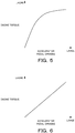
- the throttle valve opening TVO and an engine torque are related as shown in FIG. 4 .
- an increase amount of the engine torque becomes smaller.
- the relationship of the throttle valve opening TVO and the accelerator pedal opening APO is set as shown in broken line of FIG. 3 , the accelerator pedal opening APO and the engine torque show a tendency similar to the one in FIG. 4 as shown in FIG. 5 and an increase amount of the engine torque becomes smaller when the accelerator pedal opening APO increases.
- the supply of the hydraulic pressure to the low brake 32 or the reverse brake 34 of the sub-transmission mechanism 30 is normally controlled on the basis of the throttle valve opening TVO (hereinafter, this control is referred to as a "normal select control").
- FIG. 7 is a flow chart showing the engagement control in the case of operating the shift lever.
- Step S100 the controller 12 determines whether or not the garage shift has been performed. Specifically, the controller 12 determines whether or not the shift lever has been changed from the D-range to the R-range or from the R-range to the D-range within a predetermined short time set in advance. A process proceeds to Step S101 if the garage shift has been performed while proceeding to Step S103 unless the garage shift has been performed.
- Step S101 the controller 12 determines whether or not a predetermined engagement start condition is satisfied.
- the predetermined engagement start condition is a condition for starting the engagement of the low brake 32 or the reverse brake 34 except for the throttle valve opening TVO reaching a predetermined opening and, for example, a case where the engine rotation speed Ne is high and the engagement of the low brake 32 or the reverse brake 34 is started to protect the transmission 4.
- the process proceeds to Step S105 if the predetermined engagement start condition is satisfied while proceeding to Step S102 unless the predetermined engagement start condition is satisfied.
- Step S102 the controller 12 determines whether or not the accelerator pedal opening APO or the throttle valve opening TVO has become equal to or larger than a predetermined opening (threshold value).
- the predetermined opening is an opening set in advance and an opening capable of determining the driver's intention to start. The process proceeds to Step S105 if the throttle valve opening TVO is not smaller than the predetermined opening while returning to Step S101 if the throttle valve opening TVO is smaller than the predetermined opening.
- Step S103 the controller 12 determines whether or not the predetermined engagement start condition is satisfied. The process proceeds to Step S105 if the predetermined engagement start condition is satisfied while proceeding to Step S104 unless the predetermined engagement start condition is satisfied.
- Step S104 the controller 12 determines whether or not the throttle valve opening TVO has become equal to or larger than the predetermined opening. The process proceeds to Step S105 if the throttle valve opening TVO is not smaller than the predetermined opening while returning to Step S103 if the throttle valve opening TVO is smaller than the predetermined opening.
- Step S105 the controller 12 starts the supply of the hydraulic pressure to the low brake 32 or the reverse brake 34 according to the position of the shift lever and starts engaging the low brake 32 or the reverse brake 34.
- the accelerator pedal opening APO reaches the predetermined opening before the throttle valve opening TVO reaches the predetermined opening.
- the supply of the hydraulic pressure to the low brake 32 or the reverse brake 34 is started and the engagement of the low brake 32 or the reverse brake 34 is started when the accelerator pedal opening APO reaches the predetermined opening. Accordingly, the low brake 32 or the reverse brake 34 is engaged at an earlier timing than in the normal select control in which the supply of the hydraulic pressure to the low brake 32 or the reverse brake 34 is started on the basis of the throttle valve opening TVO, whereby the vehicle can be quickly started.
- the hydraulic pressure supplied to the low brake 32 or the reverse brake 34 is controlled on the basis of the accelerator pedal opening APO and the throttle valve opening TVO. Specifically, in the case of performing the garage shift, the supply of the hydraulic pressure to the low brake 32 or the reverse brake 34 is started on the basis of the accelerator pedal opening APO. Since this causes the supply of the hydraulic pressure to the low brake 32 or the reverse brake 34 to be started on the basis of the accelerator pedal opening APO at the time of the garage shift even if the throttle valve opening TVO is delayed with respect to the accelerator pedal opening APO, a delay of the engagement timing of the low brake 32 or the reverse brake 34 can be suppressed.
- the engagement timing of the low brake 32 or the reverse brake 34 is made earlier by making the hydraulic pressure supply start timing of the low brake 32 or the reverse brake 34 at the time of the garage shift earlier, but is not made earlier by a method for increasing a climb gradient of the hydraulic pressure or the like.
- the low brake 32 or the reverse brake 34 can be engaged without causing a large engagement shock.
- the second embodiment differs from the first embodiment in the engagement control when the shift lever is operated.
- An engagement control of the second embodiment when the shift lever is operated is described using a flow chart of FIG. 8 .
- Step S200 the controller 12 determines whether or not the garage shift has been performed. A process proceeds to Step S201 if the garage shift has been performed while proceeding to Step S205 unless the garage shift has been performed.
- Step S201 the controller 12 determines whether or not the accelerator pedal opening APO is not smaller than a predetermined opening (threshold value). The process proceeds to Step S202 if the accelerator pedal opening APO is not smaller than the predetermined opening while proceeding to Step S205 if the accelerator pedal opening APO is smaller than the predetermined opening.
- Step S202 the controller 12 determines whether or not the engine rotation speed Ne is lower than a predetermined rotation speed. If the garage shift has been performed and the speed of the rotation transmitted from the engine 1 to the low brake 32 or the reverse brake 34 is high, a rotation speed difference between input and output shafts of the low brake 32 or the reverse brake 34 is large. Thus, if the hydraulic pressure is supplied to the low brake 32 or the reverse brake 34 by an accelerator pedal select control to be described later or the normal select control, a slip in the low brake 32 or the reverse brake 34 becomes larger and operability may be deteriorated.
- the predetermined rotation speed is a rotation speed set in view of such a point and a rotation speed capable of judging the need to suppress the slip in the low brake 32 or the reverse brake 34.
- the process proceeds to Step S203 if the engine rotation speed Ne is lower than the predetermined rotation speed while proceeding to Step S206 if the engine rotation speed Ne is not lower than the predetermined rotation speed.
- Step S203 the controller 12 starts the accelerator pedal select control.
- the controller 12 calculates an engine torque on the basis of the accelerator pedal opening APO, calculates the hydraulic pressure supplied to the low brake 32 or the reverse brake 34 by multiplying the calculated engine torque by a coefficient based on a torque ratio of the torque converter 2, a speed ratio, an oil temperature or the like, and controls the hydraulic pressure. Since the throttle valve opening TVO is delayed with respect to the accelerator pedal opening APO in the present embodiment, the hydraulic pressure calculated on the basis of the accelerator pedal opening APO is higher than that calculated on the basis of the throttle valve opening TVO.
- Step S204 the controller 12 measures a time elapsed after the start of the accelerator pedal select control by a timer and determines whether or not a value T of the timer has reached a predetermined time.
- the predetermined time is a time set in advance. It should be noted that the predetermined time may be set on the basis of the accelerator pedal opening APO.
- the process proceeds to Step S205 when the value T of the timer reaches the predetermined time.
- the hydraulic pressure is supplied to the low brake 32 or the reverse brake 34 by the accelerator pedal select control until the value T of the timer reaches the predetermined time.
- Step S205 the controller 12 starts the normal select control.
- the controller 12 calculates the engine torque on the basis of the throttle valve opening TVO and calculates and controls the hydraulic pressure supplied to the low brake 32 or the reverse brake 34 on the basis of the calculated engine torque. If the accelerator pedal select control has been started in Step S203, a switch is made from the accelerator pedal select control to the normal select control.
- Step S206 the controller 12 starts a stall select control.
- the controller 12 maximizes the line pressure PL, calculates the engine torque on the basis of the throttle valve opening TVO and calculates and controls oil supplied to the low brake 32 or the reverse brake 34 on the basis of the calculated engine torque.
- the hydraulic pressure in the stall select control is so set that the low brake 32 or the reverse brake 34 is engaged earlier than with the hydraulic pressures in the accelerator pedal select control and the normal select control and is, for example, so set that a hydraulic pressure climb gradient is larger than in the accelerator pedal select control and the normal select control.
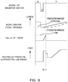
- the shift lever is changed from the R-range to the D-range and the hydraulic pressure is supplied to the low brake 32 by the accelerator pedal select control if the accelerator pedal opening APO is not smaller than the predetermined opening. Further, a time elapsed after the start of the accelerator pedal select control is measured by the timer. Since the throttle valve opening TVO is delayed with respect to the accelerator pedal opening APO, the throttle valve opening TVO is smaller than the accelerator pedal APO. In FIG. 9 , the throttle valve opening TVO is shown in dashed-dotted line.
- the hydraulic pressure supplied to the low brake 32 or the reverse brake 34 is controlled by the accelerator pedal select control after the supply of the hydraulic pressure to the low brake 32 or the reverse brake 34 is started. Since the hydraulic pressure higher than in the normal select control is supplied to the low brake 32 or the reverse brake 34 in this way, a delay of the engagement of the low brake 32 or the reverse brake 34 can be suppressed.
- the hydraulic pressure supplied to the low brake 32 or the reverse brake 34 is controlled by the accelerator pedal select control when the accelerator pedal opening APO has become equal to or larger than the predetermined opening.
- the hydraulic pressure supplied to the low brake 32 or the reverse brake 34 may be controlled by the accelerator pedal select control when the throttle valve opening TVO has become equal to or larger than the predetermined opening. Effects similar to those of the second embodiment can be obtained also by this.
- the engagement controls of the above embodiments can be used in multi-stage transmissions, continuously variable transmissions with a forward/reverse switching mechanism and the like.
Landscapes
- Engineering & Computer Science (AREA)
- General Engineering & Computer Science (AREA)
- Mechanical Engineering (AREA)
- Physics & Mathematics (AREA)
- Fluid Mechanics (AREA)
- Chemical & Material Sciences (AREA)
- Combustion & Propulsion (AREA)
- Transportation (AREA)
- Automation & Control Theory (AREA)
- Control Of Transmission Device (AREA)
- Control Of Vehicle Engines Or Engines For Specific Uses (AREA)
- Control Of Driving Devices And Active Controlling Of Vehicle (AREA)
Claims (6)
- Hydrauliksteuervorrichtung für ein Automatikgetriebe, die eine elektronisch gesteuerte Drosselvorrichtung (50) zum Ändern einer Drosselventilöffnung (TVO) eines Primärantriebs (1) durch ein elektrisches Stellglied (51) basierend auf einer Gaspedalöffnung (APO) umfasst und zum Zuführen eines Hydraulikdrucks zu einem Reibeingriffselement (32, 33, 34) eines Getriebes (4) basierend auf der Drosselventilöffnung (TVO) konfiguriert ist, umfassend:eine Gaspedalöffnung-Erfassungseinrichtung (41), die zum Erfassen der Gaspedalöffnung (APO) konfiguriert ist;eine Drosselventilöffnung-Erfassungseinrichtung (47), die zum Erfassen der Drosselventilöffnung (TVO) konfiguriert ist;eine Schalthebelposition-Erfassungseinrichtung (45), die zum Erfassen einer Position eines Schalthebels konfiguriert ist; undeine Hydrauliksteuereinrichtung (11),dadurch gekennzeichnet, dass die Hydrauliksteuereinrichtung (11) zum Steuern eines Startzeitpunkts einer Zufuhr des Hydraulikdrucks zum Reibeingriffselement (32, 33, 34) basierend auf der Gaspedalöffnung (APO) und der Drosselventilöffnung (TVO) konfiguriert ist, wenn der Schalthebel von einer Vorwärtsgangposition zu einer Rückwärtsgangposition oder von der Rückwärtsgangposition zur Vorwärtsgangposition geändert wird.
- Hydrauliksteuervorrichtung für ein Automatikgetriebe nach Anspruch 1, wobei:
die Hydrauliksteuereinrichtung (11) die Zufuhr des Hydraulikdrucks zum Reibeingriffselement (32, 33, 34) startet, wenn zumindest die Gaspedalöffnung (APO) und/oder die Drosselventilöffnung (TVO) gleichgroß oder größer als ein Schwellenwert wird, wenn der Schalthebel von der Vorwärtsgangposition zur Rückwärtsgangposition oder von der Rückwärtsgangposition zur Vorwärtsgangposition wechselt. - Hydraulische Steuervorrichtung für ein Automatikgetriebe nach Anspruch 1 oder 2, wobei:
die Hydrauliksteuereinrichtung (11) die Zufuhr des Hydraulikdrucks zum Reibeingriffselement (32, 33, 34) startet, wenn die Gaspedalöffnung (APO) gleich oder größer als ein Schwellenwert wird, wenn der Schalthebel von der Vorwärtsgangposition zur Rückwärtsgangposition oder von der Rückwärtsgangposition zur Vorwärtsgangposition wechselt. - Hydrauliksteuervorrichtung für ein Automatikgetriebe nach Anspruch 3, wobei:
die Hydrauliksteuereinrichtung (11) von der Zufuhr des Hydraulikdrucks basierend auf der Gaspedalöffnung (APO) zur Zufuhr des Hydraulikdrucks basierend auf der Drosselventilöffnung (TVO) nach Ablauf einer vorbestimmten Zeit nach einem Start der Zufuhr des Hydraulikdrucks zum Reibeingriffselement (32, 33, 34) basierend auf der Gaspedalöffnung umschaltet. - Hydrauliksteuervorrichtung für ein Automatikgetriebe nach einem der Ansprüche 1 bis 4, wobei:
die Drosselventilöffnung (TVO) kleiner als die Gaspedalöffnung (APO) ist. - Steuerverfahren für eine Hydrauliksteuervorrichtung, die eine elektronisch gesteuerte Drosselvorrichtung (50) zum Ändern einer Drosselventilöffnung (TVO) eines Primärantriebs (1) durch ein elektrisches Stellglied (51) basierend auf einer Gaspedalöffnung (APO) und zum Zuführen eines Hydraulikdrucks zu einem Reibeingriffselement (32, 33, 34) eines Getriebes (4) basierend auf der Drosselklappenöffnung (TVO) konfiguriert ist, umfassend:Erfassen der Gaspedalöffnung (APO);Erfassen der Drosselventilöffnung (TVO); undErfassen einer Position eines Schalthebels;gekennzeichnet durchSteuern eines Startzeitpunkts einer Zufuhr des Hydraulikdrucks zum Reibeingriffselement (32, 33, 34) basierend auf der Gaspedalöffnung (APO) und der Drosselventilöffnung (TVO), wenn der Schalthebel von einer Vorwärtsgangposition zu einer Rückwärtsgangposition oder von der Rückwärtsgangposition zur Vorwärtsgangposition wechselt.
Applications Claiming Priority (2)
| Application Number | Priority Date | Filing Date | Title |
|---|---|---|---|
| JP2014126672 | 2014-06-19 | ||
| PCT/JP2015/054130 WO2015194206A1 (ja) | 2014-06-19 | 2015-02-16 | 自動変速機の油圧制御装置、及びその制御方法 |
Publications (3)
| Publication Number | Publication Date |
|---|---|
| EP3159581A1 EP3159581A1 (de) | 2017-04-26 |
| EP3159581A4 EP3159581A4 (de) | 2017-07-26 |
| EP3159581B1 true EP3159581B1 (de) | 2018-10-24 |
Family
ID=54935205
Family Applications (1)
| Application Number | Title | Priority Date | Filing Date |
|---|---|---|---|
| EP15809496.1A Not-in-force EP3159581B1 (de) | 2014-06-19 | 2015-02-16 | Hydraulische steuerungsvorrichtung zur automatischen übertragung und steuerungsverfahren dafür |
Country Status (6)
| Country | Link |
|---|---|
| US (1) | US10005445B2 (de) |
| EP (1) | EP3159581B1 (de) |
| JP (1) | JP6313854B2 (de) |
| KR (1) | KR20170008259A (de) |
| CN (1) | CN106461072B (de) |
| WO (1) | WO2015194206A1 (de) |
Families Citing this family (1)
| Publication number | Priority date | Publication date | Assignee | Title |
|---|---|---|---|---|
| DE102016211391B4 (de) * | 2016-06-24 | 2020-06-18 | Zf Friedrichshafen Ag | Elektrohydraulisches Getriebesteuersystem mit einem Parksperrenventil |
Family Cites Families (16)
| Publication number | Priority date | Publication date | Assignee | Title |
|---|---|---|---|---|
| JPS631843A (ja) * | 1986-06-19 | 1988-01-06 | Mazda Motor Corp | 複合クラツチ式多段歯車変速機の制御装置 |
| US5090270A (en) * | 1988-05-12 | 1992-02-25 | Nissan Motor Co., Ltd. | Control system for automatic transmission |
| JPH07121664B2 (ja) * | 1990-09-17 | 1995-12-25 | 小松フォークリフト株式会社 | 自動変速機を備えた車両のスイッチバック走行における制動制御装置 |
| JP3630790B2 (ja) | 1995-08-31 | 2005-03-23 | ジヤトコ株式会社 | 自動変速機の作動油圧制御装置 |
| US5941792A (en) * | 1996-11-23 | 1999-08-24 | Luk Getriebe-Systeme Gmbh | Method of and apparatus for regulating crawling movements of motor vehicles |
| US5855533A (en) * | 1996-12-09 | 1999-01-05 | General Motors Corporation | Automotive powertrain control |
| JP3840079B2 (ja) | 2001-09-27 | 2006-11-01 | ジヤトコ株式会社 | トロイダル型無段変速機のスリップ防止装置 |
| JP2004278767A (ja) * | 2003-03-19 | 2004-10-07 | Suzuki Motor Corp | 車両用自動変速機の制御装置 |
| JP4146306B2 (ja) * | 2003-07-28 | 2008-09-10 | トヨタ自動車株式会社 | 自動変速機の変速制御装置 |
| JP2007170550A (ja) * | 2005-12-22 | 2007-07-05 | Toyota Motor Corp | 自動変速機の制御装置 |
| JP2008126933A (ja) * | 2006-11-24 | 2008-06-05 | Toyota Motor Corp | 車両の制御装置 |
| US7789797B2 (en) * | 2007-04-27 | 2010-09-07 | Chrysler Group Llc | Methods and systems for drive-to-neutral and neutral-to-drive transmission garage shift quality improvement |
| JP4363486B2 (ja) * | 2008-01-22 | 2009-11-11 | トヨタ自動車株式会社 | 無段変速機の制御装置および制御方法 |
| JP5283422B2 (ja) | 2008-04-23 | 2013-09-04 | ヤマハ発動機株式会社 | 船舶用推進システム、その制御装置及び制御方法 |
| CN104024700B (zh) * | 2011-11-18 | 2016-06-29 | 加特可株式会社 | 自动变速器及其起步时控制方法 |
| CN103807323B (zh) * | 2014-02-18 | 2016-03-30 | 安徽江淮汽车股份有限公司 | 双离合器自动变速器正常起步控制方法 |
-
2015
- 2015-02-16 KR KR1020167034692A patent/KR20170008259A/ko not_active Abandoned
- 2015-02-16 WO PCT/JP2015/054130 patent/WO2015194206A1/ja not_active Ceased
- 2015-02-16 JP JP2016529094A patent/JP6313854B2/ja active Active
- 2015-02-16 US US15/319,460 patent/US10005445B2/en not_active Expired - Fee Related
- 2015-02-16 EP EP15809496.1A patent/EP3159581B1/de not_active Not-in-force
- 2015-02-16 CN CN201580031292.8A patent/CN106461072B/zh not_active Expired - Fee Related
Non-Patent Citations (1)
| Title |
|---|
| None * |
Also Published As
| Publication number | Publication date |
|---|---|
| US20170320478A1 (en) | 2017-11-09 |
| JP6313854B2 (ja) | 2018-04-18 |
| US10005445B2 (en) | 2018-06-26 |
| EP3159581A1 (de) | 2017-04-26 |
| KR20170008259A (ko) | 2017-01-23 |
| CN106461072B (zh) | 2018-11-13 |
| CN106461072A (zh) | 2017-02-22 |
| EP3159581A4 (de) | 2017-07-26 |
| JPWO2015194206A1 (ja) | 2017-04-20 |
| WO2015194206A1 (ja) | 2015-12-23 |
Similar Documents
| Publication | Publication Date | Title |
|---|---|---|
| US8690733B2 (en) | Vehicle control system and control method thereof | |
| EP2546554B1 (de) | Steuerungsvorrichtung für übertragungsmechanismus und steuerungsverfahren dafür | |
| EP3064809B1 (de) | Vorrichtung zum steuern einer überbrückungskupplung | |
| KR101823244B1 (ko) | 동력 전달 장치의 제어 장치 | |
| EP2781795B1 (de) | Automatikgetriebe und verfahren zur steuerung von dessen start | |
| EP3348872A1 (de) | Fahrzeugsteuerungsvorrichtung und verfahren zur steuerung eines fahrzeugs | |
| EP3026242A1 (de) | Vorrichtung und verfahren zur fahrzeugsteuerung | |
| EP3159581B1 (de) | Hydraulische steuerungsvorrichtung zur automatischen übertragung und steuerungsverfahren dafür | |
| EP2902668B1 (de) | Stufenloses getriebe und steuerungsverfahren dafür | |
| US10549757B2 (en) | Vehicle control device and vehicle control method | |
| KR101999935B1 (ko) | 자동 변속기의 제어 장치 및 자동 변속기의 제어 방법 | |
| WO2019044789A1 (ja) | 自動変速機のセレクトソレノイド弁異常診断装置および異常診断方法 | |
| CN114096746A (zh) | 车辆的控制装置及车辆的控制方法 | |
| JP2019082187A (ja) | 自動変速機の制御装置 | |
| US10605358B2 (en) | Transmission and control method for transmission | |
| US20200347933A1 (en) | Control method for power transmission device, and control device for power transmission device | |
| CN114126937A (zh) | 车辆的控制装置及车辆的控制方法 |
Legal Events
| Date | Code | Title | Description |
|---|---|---|---|
| STAA | Information on the status of an ep patent application or granted ep patent |
Free format text: STATUS: THE INTERNATIONAL PUBLICATION HAS BEEN MADE |
|
| PUAI | Public reference made under article 153(3) epc to a published international application that has entered the european phase |
Free format text: ORIGINAL CODE: 0009012 |
|
| STAA | Information on the status of an ep patent application or granted ep patent |
Free format text: STATUS: REQUEST FOR EXAMINATION WAS MADE |
|
| 17P | Request for examination filed |
Effective date: 20170117 |
|
| AK | Designated contracting states |
Kind code of ref document: A1 Designated state(s): AL AT BE BG CH CY CZ DE DK EE ES FI FR GB GR HR HU IE IS IT LI LT LU LV MC MK MT NL NO PL PT RO RS SE SI SK SM TR |
|
| AX | Request for extension of the european patent |
Extension state: BA ME |
|
| A4 | Supplementary search report drawn up and despatched |
Effective date: 20170627 |
|
| RIC1 | Information provided on ipc code assigned before grant |
Ipc: F16D 48/06 20060101ALI20170621BHEP Ipc: F16H 61/04 20060101AFI20170621BHEP Ipc: F16D 48/02 20060101ALI20170621BHEP Ipc: F16H 59/08 20060101ALN20170621BHEP |
|
| DAX | Request for extension of the european patent (deleted) | ||
| REG | Reference to a national code |
Ref country code: DE Ref legal event code: R079 Ref document number: 602015018845 Country of ref document: DE Free format text: PREVIOUS MAIN CLASS: F16H0061040000 Ipc: F16D0048060000 |
|
| GRAP | Despatch of communication of intention to grant a patent |
Free format text: ORIGINAL CODE: EPIDOSNIGR1 |
|
| STAA | Information on the status of an ep patent application or granted ep patent |
Free format text: STATUS: GRANT OF PATENT IS INTENDED |
|
| RIC1 | Information provided on ipc code assigned before grant |
Ipc: F16H 61/06 20060101ALI20180702BHEP Ipc: B60W 30/18 20120101ALI20180702BHEP Ipc: F16D 48/06 20060101AFI20180702BHEP Ipc: F16H 59/08 20060101ALN20180702BHEP Ipc: F16H 61/04 20060101ALI20180702BHEP Ipc: F16D 48/02 20060101ALI20180702BHEP |
|
| INTG | Intention to grant announced |
Effective date: 20180801 |
|
| GRAS | Grant fee paid |
Free format text: ORIGINAL CODE: EPIDOSNIGR3 |
|
| GRAA | (expected) grant |
Free format text: ORIGINAL CODE: 0009210 |
|
| STAA | Information on the status of an ep patent application or granted ep patent |
Free format text: STATUS: THE PATENT HAS BEEN GRANTED |
|
| AK | Designated contracting states |
Kind code of ref document: B1 Designated state(s): AL AT BE BG CH CY CZ DE DK EE ES FI FR GB GR HR HU IE IS IT LI LT LU LV MC MK MT NL NO PL PT RO RS SE SI SK SM TR |
|
| RAP1 | Party data changed (applicant data changed or rights of an application transferred) |
Owner name: JATCO LTD |
|
| REG | Reference to a national code |
Ref country code: CH Ref legal event code: EP |
|
| REG | Reference to a national code |
Ref country code: IE Ref legal event code: FG4D |
|
| REG | Reference to a national code |
Ref country code: AT Ref legal event code: REF Ref document number: 1057027 Country of ref document: AT Kind code of ref document: T Effective date: 20181115 |
|
| REG | Reference to a national code |
Ref country code: DE Ref legal event code: R096 Ref document number: 602015018845 Country of ref document: DE |
|
| REG | Reference to a national code |
Ref country code: NL Ref legal event code: MP Effective date: 20181024 |
|
| REG | Reference to a national code |
Ref country code: LT Ref legal event code: MG4D |
|
| REG | Reference to a national code |
Ref country code: AT Ref legal event code: MK05 Ref document number: 1057027 Country of ref document: AT Kind code of ref document: T Effective date: 20181024 |
|
| PG25 | Lapsed in a contracting state [announced via postgrant information from national office to epo] |
Ref country code: NL Free format text: LAPSE BECAUSE OF FAILURE TO SUBMIT A TRANSLATION OF THE DESCRIPTION OR TO PAY THE FEE WITHIN THE PRESCRIBED TIME-LIMIT Effective date: 20181024 |
|
| PG25 | Lapsed in a contracting state [announced via postgrant information from national office to epo] |
Ref country code: ES Free format text: LAPSE BECAUSE OF FAILURE TO SUBMIT A TRANSLATION OF THE DESCRIPTION OR TO PAY THE FEE WITHIN THE PRESCRIBED TIME-LIMIT Effective date: 20181024 Ref country code: IS Free format text: LAPSE BECAUSE OF FAILURE TO SUBMIT A TRANSLATION OF THE DESCRIPTION OR TO PAY THE FEE WITHIN THE PRESCRIBED TIME-LIMIT Effective date: 20190224 Ref country code: BG Free format text: LAPSE BECAUSE OF FAILURE TO SUBMIT A TRANSLATION OF THE DESCRIPTION OR TO PAY THE FEE WITHIN THE PRESCRIBED TIME-LIMIT Effective date: 20190124 Ref country code: LT Free format text: LAPSE BECAUSE OF FAILURE TO SUBMIT A TRANSLATION OF THE DESCRIPTION OR TO PAY THE FEE WITHIN THE PRESCRIBED TIME-LIMIT Effective date: 20181024 Ref country code: HR Free format text: LAPSE BECAUSE OF FAILURE TO SUBMIT A TRANSLATION OF THE DESCRIPTION OR TO PAY THE FEE WITHIN THE PRESCRIBED TIME-LIMIT Effective date: 20181024 Ref country code: PL Free format text: LAPSE BECAUSE OF FAILURE TO SUBMIT A TRANSLATION OF THE DESCRIPTION OR TO PAY THE FEE WITHIN THE PRESCRIBED TIME-LIMIT Effective date: 20181024 Ref country code: AT Free format text: LAPSE BECAUSE OF FAILURE TO SUBMIT A TRANSLATION OF THE DESCRIPTION OR TO PAY THE FEE WITHIN THE PRESCRIBED TIME-LIMIT Effective date: 20181024 Ref country code: LV Free format text: LAPSE BECAUSE OF FAILURE TO SUBMIT A TRANSLATION OF THE DESCRIPTION OR TO PAY THE FEE WITHIN THE PRESCRIBED TIME-LIMIT Effective date: 20181024 Ref country code: NO Free format text: LAPSE BECAUSE OF FAILURE TO SUBMIT A TRANSLATION OF THE DESCRIPTION OR TO PAY THE FEE WITHIN THE PRESCRIBED TIME-LIMIT Effective date: 20190124 Ref country code: FI Free format text: LAPSE BECAUSE OF FAILURE TO SUBMIT A TRANSLATION OF THE DESCRIPTION OR TO PAY THE FEE WITHIN THE PRESCRIBED TIME-LIMIT Effective date: 20181024 |
|
| PG25 | Lapsed in a contracting state [announced via postgrant information from national office to epo] |
Ref country code: AL Free format text: LAPSE BECAUSE OF FAILURE TO SUBMIT A TRANSLATION OF THE DESCRIPTION OR TO PAY THE FEE WITHIN THE PRESCRIBED TIME-LIMIT Effective date: 20181024 Ref country code: RS Free format text: LAPSE BECAUSE OF FAILURE TO SUBMIT A TRANSLATION OF THE DESCRIPTION OR TO PAY THE FEE WITHIN THE PRESCRIBED TIME-LIMIT Effective date: 20181024 Ref country code: SE Free format text: LAPSE BECAUSE OF FAILURE TO SUBMIT A TRANSLATION OF THE DESCRIPTION OR TO PAY THE FEE WITHIN THE PRESCRIBED TIME-LIMIT Effective date: 20181024 Ref country code: GR Free format text: LAPSE BECAUSE OF FAILURE TO SUBMIT A TRANSLATION OF THE DESCRIPTION OR TO PAY THE FEE WITHIN THE PRESCRIBED TIME-LIMIT Effective date: 20190125 Ref country code: PT Free format text: LAPSE BECAUSE OF FAILURE TO SUBMIT A TRANSLATION OF THE DESCRIPTION OR TO PAY THE FEE WITHIN THE PRESCRIBED TIME-LIMIT Effective date: 20190224 |
|
| REG | Reference to a national code |
Ref country code: DE Ref legal event code: R097 Ref document number: 602015018845 Country of ref document: DE |
|
| PG25 | Lapsed in a contracting state [announced via postgrant information from national office to epo] |
Ref country code: CZ Free format text: LAPSE BECAUSE OF FAILURE TO SUBMIT A TRANSLATION OF THE DESCRIPTION OR TO PAY THE FEE WITHIN THE PRESCRIBED TIME-LIMIT Effective date: 20181024 Ref country code: IT Free format text: LAPSE BECAUSE OF FAILURE TO SUBMIT A TRANSLATION OF THE DESCRIPTION OR TO PAY THE FEE WITHIN THE PRESCRIBED TIME-LIMIT Effective date: 20181024 Ref country code: DK Free format text: LAPSE BECAUSE OF FAILURE TO SUBMIT A TRANSLATION OF THE DESCRIPTION OR TO PAY THE FEE WITHIN THE PRESCRIBED TIME-LIMIT Effective date: 20181024 |
|
| PG25 | Lapsed in a contracting state [announced via postgrant information from national office to epo] |
Ref country code: SM Free format text: LAPSE BECAUSE OF FAILURE TO SUBMIT A TRANSLATION OF THE DESCRIPTION OR TO PAY THE FEE WITHIN THE PRESCRIBED TIME-LIMIT Effective date: 20181024 Ref country code: EE Free format text: LAPSE BECAUSE OF FAILURE TO SUBMIT A TRANSLATION OF THE DESCRIPTION OR TO PAY THE FEE WITHIN THE PRESCRIBED TIME-LIMIT Effective date: 20181024 Ref country code: SK Free format text: LAPSE BECAUSE OF FAILURE TO SUBMIT A TRANSLATION OF THE DESCRIPTION OR TO PAY THE FEE WITHIN THE PRESCRIBED TIME-LIMIT Effective date: 20181024 Ref country code: RO Free format text: LAPSE BECAUSE OF FAILURE TO SUBMIT A TRANSLATION OF THE DESCRIPTION OR TO PAY THE FEE WITHIN THE PRESCRIBED TIME-LIMIT Effective date: 20181024 |
|
| PLBE | No opposition filed within time limit |
Free format text: ORIGINAL CODE: 0009261 |
|
| STAA | Information on the status of an ep patent application or granted ep patent |
Free format text: STATUS: NO OPPOSITION FILED WITHIN TIME LIMIT |
|
| REG | Reference to a national code |
Ref country code: DE Ref legal event code: R119 Ref document number: 602015018845 Country of ref document: DE |
|
| REG | Reference to a national code |
Ref country code: CH Ref legal event code: PL |
|
| 26N | No opposition filed |
Effective date: 20190725 |
|
| GBPC | Gb: european patent ceased through non-payment of renewal fee |
Effective date: 20190216 |
|
| PG25 | Lapsed in a contracting state [announced via postgrant information from national office to epo] |
Ref country code: MC Free format text: LAPSE BECAUSE OF FAILURE TO SUBMIT A TRANSLATION OF THE DESCRIPTION OR TO PAY THE FEE WITHIN THE PRESCRIBED TIME-LIMIT Effective date: 20181024 Ref country code: SI Free format text: LAPSE BECAUSE OF FAILURE TO SUBMIT A TRANSLATION OF THE DESCRIPTION OR TO PAY THE FEE WITHIN THE PRESCRIBED TIME-LIMIT Effective date: 20181024 Ref country code: LU Free format text: LAPSE BECAUSE OF NON-PAYMENT OF DUE FEES Effective date: 20190216 |
|
| REG | Reference to a national code |
Ref country code: BE Ref legal event code: MM Effective date: 20190228 |
|
| REG | Reference to a national code |
Ref country code: IE Ref legal event code: MM4A |
|
| PG25 | Lapsed in a contracting state [announced via postgrant information from national office to epo] |
Ref country code: LI Free format text: LAPSE BECAUSE OF NON-PAYMENT OF DUE FEES Effective date: 20190228 Ref country code: CH Free format text: LAPSE BECAUSE OF NON-PAYMENT OF DUE FEES Effective date: 20190228 |
|
| PG25 | Lapsed in a contracting state [announced via postgrant information from national office to epo] |
Ref country code: GB Free format text: LAPSE BECAUSE OF NON-PAYMENT OF DUE FEES Effective date: 20190216 Ref country code: DE Free format text: LAPSE BECAUSE OF NON-PAYMENT OF DUE FEES Effective date: 20190903 Ref country code: IE Free format text: LAPSE BECAUSE OF NON-PAYMENT OF DUE FEES Effective date: 20190216 |
|
| PG25 | Lapsed in a contracting state [announced via postgrant information from national office to epo] |
Ref country code: FR Free format text: LAPSE BECAUSE OF NON-PAYMENT OF DUE FEES Effective date: 20190228 Ref country code: BE Free format text: LAPSE BECAUSE OF NON-PAYMENT OF DUE FEES Effective date: 20190228 |
|
| PG25 | Lapsed in a contracting state [announced via postgrant information from national office to epo] |
Ref country code: TR Free format text: LAPSE BECAUSE OF FAILURE TO SUBMIT A TRANSLATION OF THE DESCRIPTION OR TO PAY THE FEE WITHIN THE PRESCRIBED TIME-LIMIT Effective date: 20181024 |
|
| PG25 | Lapsed in a contracting state [announced via postgrant information from national office to epo] |
Ref country code: MT Free format text: LAPSE BECAUSE OF NON-PAYMENT OF DUE FEES Effective date: 20190216 |
|
| PG25 | Lapsed in a contracting state [announced via postgrant information from national office to epo] |
Ref country code: CY Free format text: LAPSE BECAUSE OF FAILURE TO SUBMIT A TRANSLATION OF THE DESCRIPTION OR TO PAY THE FEE WITHIN THE PRESCRIBED TIME-LIMIT Effective date: 20181024 |
|
| PG25 | Lapsed in a contracting state [announced via postgrant information from national office to epo] |
Ref country code: HU Free format text: LAPSE BECAUSE OF FAILURE TO SUBMIT A TRANSLATION OF THE DESCRIPTION OR TO PAY THE FEE WITHIN THE PRESCRIBED TIME-LIMIT; INVALID AB INITIO Effective date: 20150216 |
|
| PG25 | Lapsed in a contracting state [announced via postgrant information from national office to epo] |
Ref country code: MK Free format text: LAPSE BECAUSE OF FAILURE TO SUBMIT A TRANSLATION OF THE DESCRIPTION OR TO PAY THE FEE WITHIN THE PRESCRIBED TIME-LIMIT Effective date: 20181024 |