EP3159662B1 - Sonde à corde, détecteur de niveau et procédé de fabrication d'une sonde à corde - Google Patents
Sonde à corde, détecteur de niveau et procédé de fabrication d'une sonde à corde Download PDFInfo
- Publication number
- EP3159662B1 EP3159662B1 EP16191918.8A EP16191918A EP3159662B1 EP 3159662 B1 EP3159662 B1 EP 3159662B1 EP 16191918 A EP16191918 A EP 16191918A EP 3159662 B1 EP3159662 B1 EP 3159662B1
- Authority
- EP
- European Patent Office
- Prior art keywords
- probe
- cable
- measuring
- receiving opening
- measuring cable
- Prior art date
- Legal status (The legal status is an assumption and is not a legal conclusion. Google has not performed a legal analysis and makes no representation as to the accuracy of the status listed.)
- Active
Links
Images




Classifications
-
- G—PHYSICS
- G01—MEASURING; TESTING
- G01F—MEASURING VOLUME, VOLUME FLOW, MASS FLOW OR LIQUID LEVEL; METERING BY VOLUME
- G01F23/00—Indicating or measuring liquid level or level of fluent solid material, e.g. indicating in terms of volume or indicating by means of an alarm
- G01F23/22—Indicating or measuring liquid level or level of fluent solid material, e.g. indicating in terms of volume or indicating by means of an alarm by measuring physical variables, other than linear dimensions, pressure or weight, dependent on the level to be measured, e.g. by difference of heat transfer of steam or water
- G01F23/28—Indicating or measuring liquid level or level of fluent solid material, e.g. indicating in terms of volume or indicating by means of an alarm by measuring physical variables, other than linear dimensions, pressure or weight, dependent on the level to be measured, e.g. by difference of heat transfer of steam or water by measuring the variations of parameters of electromagnetic or acoustic waves applied directly to the liquid or fluent solid material
- G01F23/284—Electromagnetic waves
-
- G—PHYSICS
- G01—MEASURING; TESTING
- G01F—MEASURING VOLUME, VOLUME FLOW, MASS FLOW OR LIQUID LEVEL; METERING BY VOLUME
- G01F23/00—Indicating or measuring liquid level or level of fluent solid material, e.g. indicating in terms of volume or indicating by means of an alarm
- G01F23/0023—Indicating or measuring liquid level or level of fluent solid material, e.g. indicating in terms of volume or indicating by means of an alarm with a probe suspended by a wire or thread
-
- G—PHYSICS
- G01—MEASURING; TESTING
- G01S—RADIO DIRECTION-FINDING; RADIO NAVIGATION; DETERMINING DISTANCE OR VELOCITY BY USE OF RADIO WAVES; LOCATING OR PRESENCE-DETECTING BY USE OF THE REFLECTION OR RERADIATION OF RADIO WAVES; ANALOGOUS ARRANGEMENTS USING OTHER WAVES
- G01S13/00—Systems using the reflection or reradiation of radio waves, e.g. radar systems; Analogous systems using reflection or reradiation of waves whose nature or wavelength is irrelevant or unspecified
- G01S13/02—Systems using reflection of radio waves, e.g. primary radar systems; Analogous systems
- G01S13/06—Systems determining position data of a target
- G01S13/08—Systems for measuring distance only
- G01S13/10—Systems for measuring distance only using transmission of interrupted, pulse modulated waves
-
- G—PHYSICS
- G01—MEASURING; TESTING
- G01S—RADIO DIRECTION-FINDING; RADIO NAVIGATION; DETERMINING DISTANCE OR VELOCITY BY USE OF RADIO WAVES; LOCATING OR PRESENCE-DETECTING BY USE OF THE REFLECTION OR RERADIATION OF RADIO WAVES; ANALOGOUS ARRANGEMENTS USING OTHER WAVES
- G01S13/00—Systems using the reflection or reradiation of radio waves, e.g. radar systems; Analogous systems using reflection or reradiation of waves whose nature or wavelength is irrelevant or unspecified
- G01S13/88—Radar or analogous systems specially adapted for specific applications
-
- G—PHYSICS
- G01—MEASURING; TESTING
- G01F—MEASURING VOLUME, VOLUME FLOW, MASS FLOW OR LIQUID LEVEL; METERING BY VOLUME
- G01F23/00—Indicating or measuring liquid level or level of fluent solid material, e.g. indicating in terms of volume or indicating by means of an alarm
- G01F23/22—Indicating or measuring liquid level or level of fluent solid material, e.g. indicating in terms of volume or indicating by means of an alarm by measuring physical variables, other than linear dimensions, pressure or weight, dependent on the level to be measured, e.g. by difference of heat transfer of steam or water
- G01F23/26—Indicating or measuring liquid level or level of fluent solid material, e.g. indicating in terms of volume or indicating by means of an alarm by measuring physical variables, other than linear dimensions, pressure or weight, dependent on the level to be measured, e.g. by difference of heat transfer of steam or water by measuring variations of capacity or inductance of capacitors or inductors arising from the presence of liquid or fluent solid material in the electric or electromagnetic fields
- G01F23/263—Indicating or measuring liquid level or level of fluent solid material, e.g. indicating in terms of volume or indicating by means of an alarm by measuring physical variables, other than linear dimensions, pressure or weight, dependent on the level to be measured, e.g. by difference of heat transfer of steam or water by measuring variations of capacity or inductance of capacitors or inductors arising from the presence of liquid or fluent solid material in the electric or electromagnetic fields by measuring variations in capacitance of capacitors
- G01F23/268—Indicating or measuring liquid level or level of fluent solid material, e.g. indicating in terms of volume or indicating by means of an alarm by measuring physical variables, other than linear dimensions, pressure or weight, dependent on the level to be measured, e.g. by difference of heat transfer of steam or water by measuring variations of capacity or inductance of capacitors or inductors arising from the presence of liquid or fluent solid material in the electric or electromagnetic fields by measuring variations in capacitance of capacitors mounting arrangements of probes
-
- G—PHYSICS
- G01—MEASURING; TESTING
- G01F—MEASURING VOLUME, VOLUME FLOW, MASS FLOW OR LIQUID LEVEL; METERING BY VOLUME
- G01F23/00—Indicating or measuring liquid level or level of fluent solid material, e.g. indicating in terms of volume or indicating by means of an alarm
- G01F23/80—Arrangements for signal processing
- G01F23/802—Particular electronic circuits for digital processing equipment
-
- H—ELECTRICITY
- H01—ELECTRIC ELEMENTS
- H01Q—ANTENNAS, i.e. RADIO AERIALS
- H01Q1/00—Details of, or arrangements associated with, antennas
- H01Q1/12—Supports; Mounting means
- H01Q1/22—Supports; Mounting means by structural association with other equipment or articles
- H01Q1/225—Supports; Mounting means by structural association with other equipment or articles used in level-measurement devices, e.g. for level gauge measurement
Definitions
- the present invention relates to the technical field of metrology.
- the present invention relates to radar, transit time or reflection metrology.
- the present invention describes a rope probe, designed for a level gauge, a level gauge and a method for producing a rope probe.
- measuring probes consisting of a measuring cable and a gravity weight or centering weight are frequently used.
- the probes help to measure levels by evaluating reflections, run times and / or echoes of guided microwaves or guided radar waves.
- waves or signals are propagated which propagate along a probe within a container and which are reflected at prominent locations in the container, such as at junctions between dissimilar materials. These reflections can be translated as echoes in one Indicate echo diagram.
- the container it can be determined whether the container is empty, that is, whether it is only filled with air, or whether a product or bulk material is in the container.
- a level measurement is only performed when the probe touches the medium or medium or is immersed in the medium or medium. As long as the probe is not in contact with the medium whose level is to be determined results in a dead zone.
- a gravity weight is attached at one end of a rope probe.
- the gravity weight or centering weight serves to keep the measuring cable of the measuring probe in a stable position within a container in order to ensure the most uniform possible immersion of the end of the measuring cable into the filling material.
- a weight device for a probe is for example the publication US 2015168203 A1 refer to.
- the publication DE 10 2005 015 548 B4 describes a device for determining and / or monitoring the level of a medium in which it is exploited that the electromagnetic signals come into contact with a medium and are thus influenced by the medium to allow statements about the medium can.
- document DE 42 24 635 A1 relates to a probe for monitoring a medium.
- an electrode cable is bent in a Seilendkapsel the probe sharp upwards, so that the bent end portion extends directly adjacent to the preceding section of the electrode cable.
- a sleeve radially surrounds both sections.
- Document G 91 03 122 relates to a level probe, which is based on the capacitive measuring principle.
- the probe rope and the container wall form the two plates of a capacitor, wherein a distance of the plates by an expanding membrane decreases and thus increases the capacity.
- the capacity thus represents a measure of the filling state of the membrane.
- WO 2004/042333 A1 describes a device for tightening a rope of a level gauge, wherein at a reaching into a container, free end portion of the rope, a final weight is arranged with a through recess.
- a rope probe having a measuring cord and a probe-end device.
- the probe-end device may be provided independently of the measuring cable and may be connected to the measuring cable during manufacture of the cable probe by being adapted to receive the measuring cable and in particular a measuring cable end section or end section of the measuring cable to form the cable probe.
- the measuring cable has a predeterminable cross section.
- the probe-end device has a probe-end body having a receiving opening for an end portion of the measuring cord.
- the receiving opening has a wall which is set up to predetermine a profile of an end section of the measuring cable inserted into the receiving opening.
- the wall is further configured to space the end portion of the measuring cable inserted into the receiving opening from at least one boundary or surface of the probe body.
- the end portion of the metering rope or the end of the metering rope may also be referred to as the metering end, although the metering end is actually the end of the metering end section, the extreme end of the metering cable or the distal end of the metering cable.
- the rope probe may have a measuring cable with a predeterminable cross section.
- the probe-end device may include a probe-end body or probe body having a receiving opening for an end portion of the measuring cord or for a measuring cable end.
- the probe end body further has a cavity adjoining the receiving opening.
- a passage from an environment of the probe-end body into the interior of the probe-end body and in particular into the cavity of the probe-end body is possible substantially only through the receiving opening.
- the cavity in the probe end body receives the end portion of the measuring cord, the measuring rope end portion or the measuring cord end when the measuring cord is inserted into the probe end body.
- the receiving opening can be adapted to the cross section of the measuring cable such that the receiving opening can be closed or sealed with the measuring cable so that the cavity can be separated from an environment when the measuring cable is inserted into the cavity.
- the receiving opening may be adapted to the cross-section of the measuring cable in such a way that a sealing of the cavity with respect to an outer area is made possible by inserting the measuring cable into the receiving opening.
- predeterminable measuring cables with standardized cross-sectional areas and cross-sectional shapes may exist, as well as with predeterminable cable lengths.
- a suitable probe end device may exist for each of these predeterminable metering cables or fair sectional shapes, which may be indicated by a trade fair type.
- the cavity is formed by the wall of the receiving opening and has a length which is greater than the length which corresponds to the vertical distance from the receiving opening to an opposing boundary of the probe body.
- the boundary may be an outer surface and / or a lateral surface of the probe end body.
- the boundary is designed to substantially separate the cavity from the environment.
- in the area of the receiving opening the thickest part of the Be probe end body.
- the probe end body can, because of this separation effect or the insulating effect, the spigot end portion of the measuring cable of a Isolate environment and in particular from a material present in the environment and / or an atmosphere.
- the probe end body may prevent a direct contact of the inserted end portion of the measuring cable with an atmosphere or with a filling material.
- the predeterminable cross-section may have any shape, for example a circular shape with a circular cross-sectional area.
- the cross-section for which the receiving opening is provided may determine the cross-sectional area of the receiving opening.
- the cavity After insertion of the measuring cable into the cavity, the cavity can be completely or partially filled with the measuring cable.
- the cavity which is not filled by the measuring cable, can be filled by a high-density filling material.
- this filler may have a large mass to increase the weight of the probe body.
- the cavity may have a volume equal to or greater than the volume having the inserted end portion of the measuring cable or the inserted Messeilendabites.
- the length and the cross-sectional area of the measuring cable determine the necessary minimum volume of the cavity.
- the minimum volume of the cavity may be predetermined by the length of the measuring cable end section to be inserted and the cross-sectional area of the measuring cable, the minimum volume being at least necessary. to pick up the measuring cable end section.
- the cavity for a measuring wire having a round cross section may have a volume which is larger than that Volume of a cylinder having a base area which corresponds to the cross-section of the receiving opening, and a length which corresponds to the vertical distance from the receiving opening to an opposite boundary of the probe body.
- the rope probe has a measuring cable, which is designed for guiding a microwave or a radar wave.
- the wall of the receiving opening may determine the course of the measuring cable.
- the wall of the probe end body and in particular the wall of the receiving opening may be formed such that it predetermines a course of the exhibition end section.
- the wall may ensure that the course of the Meßseilendabites is specifiable and does not follow its natural course, which it would take, for example, by the action of gravity.
- the wall may ensure that the fairing end portion is spaced from a predeterminable outer surface of the probe end body.
- the wall of the probe body may be used as an insulator. For example, a measuring wire spaced from the lower surface may be prevented from coming into contact with a metal surface of a container bottom disposed below the lower surface.
- the cavity or interior of the probe body can be sealed by means of the inserted measuring cable.
- the cavity may also be in the inserted state wholly or partly from the Meßseilendabrough filled out.
- the receiving opening of the probe end body can be adapted to the cross section of the measuring cable such that a press fit results when the measuring cable is inserted into the receiving opening.
- a press fit can be produced, for example, by the cross section of the receiving opening being smaller than the cross section of the measuring cable.
- the interference fit may be made by temporarily heating prior to insertion of the measuring cable into the receiving opening of the probe-end device and ensuring that the measuring cable end is held by friction forces from the receiving opening and / or the cavity wall in the interior of the probe end device.
- a level gauge has an electronic device and the rope probe according to the invention.
- the electronic device is connected to the measuring cable and designed for transmitting and / or receiving an electromagnetic wave.
- the electronic device may also have an evaluation device in order to generate and evaluate, for example, a measurement curve or echo curve from the transmitted and / or received signals.
- the electronic device in particular the evaluation device, may use methods of digital signal processing and, for example, calculate a level height from a measured transit time and display it.
- a method of making the rope probe of the invention is provided.
- the method includes providing a probe end body and creating a receiving opening for insertion of an end portion of a measuring cord into the probe body. Furthermore, the method comprises forming a wall of the receiving opening and / or the probe end body such that the wall can predetermine a course of the measuring cable end section inserted into the receiving opening.
- the Wall is also shaped such that it spaced from the measuring cable end portion inserted into the receiving opening of at least one boundary, a surface and or a lateral surface of the probe end body.
- the method comprises creating the cavity present in the probe-end body according to the invention, wherein the cavity adjoins the receiving opening.
- the method comprises adapting the receiving opening to the cross section of the measuring cable such that the receiving opening can be closed or sealed by means of the measuring cable and that the cavity can be separated from an environment when the measuring cable is inserted into the cavity.
- the method may, for example, comprise the formation of a length of the cavity according to the invention which is greater than the length which corresponds to the vertical distance from the receiving opening to an opposing boundary of the probe body.
- the boundary and in particular the wall between the boundary and the cavity is designed to substantially separate the cavity from the environment and / or from a filling material present in the environment.
- the boundary may be an outer surface or a lateral surface of the probe body.
- the method comprises forming a volume of the cavity such that the volume is greater than the volume of a virtual cylinder or comparative cylinder having a footprint corresponding to the cross-section of the receiving aperture and having a length which is the perpendicular distance of the receiving opening corresponds to an opposing boundary of the probe end body, wherein the limit is arranged to substantially separate the cavity from the environment.
- a computer-readable storage medium may be indicated which has a program code which, when executed by a processor, the Process for producing a probe-end device or probe device performs.
- a computer program product may be indicated which includes program code which, when executed by a processor, directs the processor to perform the method of manufacturing a probe device.
- the program code may be instructions for a computerized numerical control (CNC) machine or for a 3D printer.
- CNC computerized numerical control
- measuring probes or probe devices are frequently used, which have a measuring cable and a gravity weight, centering weight or a probe end device.
- the probe weight used with rope probes or with a corresponding probe device for keeping the rope tight may cause interference with measurements in the area of a probe end which is connected to the probe weight.
- Measuring interference can occur in the region of a probe end, which lies opposite an end of a measuring cable, which end is connected to an electronic device.
- the disturbances can be caused by inhomogeneities at the transition from the measuring cable to the probe weight, which result, for example, from the attachment of the weight to the free end of the probe.
- Disturbing for example, an abrupt thickening in the transition region from the cross section of the measuring cable to the cross section of the probe weight effect, which thickening is provided to produce the highest possible weight at the probe end, especially when the probe weight is solid made of solid material.
- An inhomogeneous transition or thickening or deformation can affect the RF (Radio Frequency) behavior of a probe so that unwanted clutter occurs. But disturbances can also arise when the measuring cable comes into contact with an undesired other object, for example with a container wall.
- An interference echo may be an echo which is visible in a measured echo curve, but which is not related to a desired measurement object, such as the level or transition between different materials.
- a useful echo is an echo which is generated by an inhomogeneity whose property or position is of interest.
- a useful echo for example, is an echo that results from a level or an interface between two or more materials.
- the false echo becomes a disturbing factor when it has an influence on the interesting useful echo. False echoes that lie far away from the useful echo can be distinguished clearly from a useful echo.
- Another form of echo is an echo which arises at the end of the measuring cable and in particular at the farthest or outermost end of the measuring cable, i. E. at the substantially open end of the Messeilendabitess.
- This end echo can be used on the one hand to identify the end of the measuring cable in an echo curve and can therefore be qualified as a true echo. On the other hand, it may, however, have an effect on the level of echo caused by the fill level and thus interfere with the detection of the wanted echo. Thus, the end echo can have a useful and a disturbing effect.
- the level when the level is in the range of Messseilendes and the measuring cable is substantially perpendicular, it can lead to the disturbing effect of the tail echo.
- the end echo and the level echo are close together, so that a dead zone can arise in which the end echo has such a large influence on the level echo that a level measurement is not possible.
- the dead area can be of an order of magnitude of 90 mm, so that when using such a probe under the assumption of the utilization of the entire container height as a fair length anyway only a level above 90mm from the bottom of the container can be determined. It may be desirable to provide a rope probe with as little dead zone as possible.
- a dead zone may denote the length of a measuring cable end portion which is at least necessary to produce a sufficiently long end portion of a measuring cable so that the false echo generated at the distal end of the measuring cable will not affect a useful echo produced by the level plus a length equal to a Tank bottom reaches to the far end of the fair.
- a dead band of 90 mm may mean that the end of a probe must dip at least 90 mm into the contents to produce a useful echo, which can be distinguished from the clutter caused by the probe end. This assumption should be fulfilled, in particular, when the filling material is a poorly reflecting material.
- the end echo essentially arises at a distance to the electronic device or coupling device which corresponds to the probe length determined by the measuring cable length and / or the length of the probe transmitting device or the probe weight.
- Constructive variants and shaping of the probe weight can minimize the interference caused by the impurities caused by false echoes, so that a desired useful echo is more distinct from a false echo.
- probe weights of different lengths, different diameters and different masses can be used. However, even by varying the shape of the probe weights in low-reflectance fillers, only a deadband on the order of 90 mm may be achieved.
- the probe end device according to the invention should therefore be such that the distance between the remote end of the measuring cable and an immersion position in a filling material is artificially prolonged.
- the fairing end is kept away from or isolated from an impurity, for example from a container wall. Due to the artificial extension, the position shown in the echo curve of the false echo occurring at the remote end of the fair from the position of the useful echo, which is caused by the interface of the level, can be pulled so far apart that affect the two echoes in the echo curve substantially , For the pulling apart, the physical effect may be exploited that the guided electromagnetic wave propagates substantially independently of the shape of the measuring cable along the measuring cable and the travel time required for this propagation is used as the basis for a position of an echo represented in the echo curve.
- An extension of the measuring cable without touching the container bottom and / or without a container wall can be achieved by stowing the measuring cable end section as far as possible within a probe end device, in particular within a tight weight and / or within a centering weight.
- the probe-end body of the probe-end device may be arranged to predetermine the course of the measuring-cable end portion and / or to isolate or space the measuring-cable end portion from an impurity.
- the probe end body may be arranged so that the contents can at least partially come into contact with the inserted measuring cable.
- the probe end body of the probe end device for receiving the Meßseilendabitess may be set so that the course of the measuring cable is predetermined, and that the probe end body the measuring cable relative to the environment and in particular against the contents and / or compared to a container bottom substantially separated, spaced or isolated.
- the wall defines a cavity within the probe body, with the cavity adjacent to the receiving opening.
- the receiving opening is adapted to the cross-section of the measuring cable such that the receiving opening can be closed with the measuring cable, so that the cavity can be separated from an environment when the measuring cable is inserted in the cavity.
- the cavity has a length which is greater than the length of the vertical distance from the receiving opening to a opposite the receiving opening arranged boundary of the probe end body.
- the boundary is designed to substantially separate the cavity from the environment.
- the boundary in one example, may be the surface of the probe body.
- a filling material can be kept away from the measuring cable, as a result of which the propagation of an electromagnetic wave guided by the measuring cable is substantially not influenced by the product.
- the probe body, the wall and / or the cavity in the probe body are arranged such that a shape of the inserted Meßseilendabitess is predeterminable by the probe body and / or through the cavity.
- the length of the measuring cable may be selected such that it substantially corresponds to the container height.
- a freely movable probe end may be positioned close to a container bottom.
- the measuring cable can be made of wire mesh or another flexible. Consequently, the measuring cable end portion would extend as long as possible, when the end is left free to the force of gravity.
- the course of an otherwise loose end can be influenced such that the end of the boundary of the probe body and thus also kept away from the container bottom, spaced or isolated. It is prevented by influencing the course that the Meßseilende fills the entire length of a container, as would be the case in an uncontrolled exposure of the measuring cable end of gravity.
- the probe end device forms a platform which keeps the Meßseilendabterrorism away from the container bottom and / or from a container wall or isolated and their weight simultaneously contributes to the tightening of the remaining measuring cable.
- a course of the Meßseilendabitess can be generated, which is directed parallel to a container bottom or against gravity.
- the probe-end device may allow a fairing portion disposed outside the probe-end device to be taut by the weight of the probe-end device and / or the measuring-wire end portion therein while the end portion of the measuring-wire extending within the probe-end device is unstressed or slack.
- the cavity has a length and the cross section of the receiving opening, wherein the cross section of the cavity over the entire length of the cavity corresponds to the cross section of the receiving opening.
- the cavity may substantially conform to the course of the metering end section and may affect the shape of the metering end section without creating an air-filled cavity that produces only light weight for the probe end body.
- the entire cavity can be formed as a press fit, so that the cavity alone can form such a good attachment for the Meßseilendabsacrificing that a fastening device at the distal end of the measuring cable is not necessary.
- the measuring cable end portion is loosely located within the cavity so that the measuring cable end portion is held within the probe body substantially only by the interference fit formed by the receiving aperture.
- the shape of the course of the Meßseilendabites is not predetermined in the interior of the cavity.
- the probe body has a predeterminable weight.
- a more or less severe probe end device may be required.
- the weight of the probe-end device can be influenced by the size of the cavity but also by the size of the probe body and / or the density of the material of the probe body, so that differently sized probe end devices can be provided for different measuring cables and different applications.
- the cavity is L-shaped, U-shaped, and / or helical.
- These different shapes of the cavity make it possible to deviate the Meßseilendabterrorism from a vertical position, which could lead to abutment of the Messseilendes to a container bottom, and to use a different spatial direction for the extension of Meßseilendabitess.
- the Meßseilendabêt may be spirally wound by a spiral-shaped cavity in a direction parallel to the container bottom level and thus fill the available area well. Consequently, not only a length of gravity of the measuring cable may be used as a length for the propagation of the electromagnetic wave, but also a horizontally to the direction of gravity extending portion of the measuring cable, which is held by the probe body in this position.
- the probe body is made of plastic, for example PTFE (polytetrafluoroethylene), PP (polypropylene), PE (polyethylene), PEEK (polyetheretherketone), ceramic and / or metal.
- PTFE polytetrafluoroethylene
- PP polypropylene
- PE polyethylene
- PEEK polyetheretherketone
- the cavity has a fastener or cable fixation for a remote metering cable end.
- the pressing force of the receiving opening caused by the sealing or pressing may not be sufficient to hold the probe-end device to the measuring cable.
- This fastening device may have a clamp or, for example, a screw with which the measuring cable end can be fixed.
- the probe body has a centering device and / or a spacing device, wherein the centering device and / or the spacing device is / are arranged to hold a measuring cable inserted into the probe body in a predeterminable position.
- a centering device may be formed as a disc with a defined diameter.
- a spacing device may be formed as a cup or cylinder, in the middle of which the measuring cable runs coaxially. The centering device and the spacing device can cooperate in order to hold the cable in the predeterminable position.
- the measuring cable can be fixed, for example, at a predeterminable distance from an edge region of the probe end device. This spacing can be helpful if the measuring cable is to be fastened in a standpipe and the measuring cable is to be held in the most central or coaxial position possible.
- the probe end body and / or the spacing device is disc-shaped, barrel-shaped, star-shaped and / or spoke-wheel-shaped.
- the probe end body and / or the spacing device is designed as a plastic web.
- the various embodiments of the probe end body or the cable guide make it possible to influence the weight of the probe end body.
- a disk or star-shaped probe body can ensure that the contents can easily penetrate between the spokes and re-circulate the Meßseilendabêt, without coming into direct contact with the Messseilendabterrorism.
- a permeable probe body can allow a level to penetrate into the probe weight and allow for measurement of the level near the receiving aperture, thus keeping a dead zone at the probe tip small. If the probe weight or the probe-end device is designed as a solid cone, then a useful echo can be determined substantially only in the region above the cone in which the measuring cable enters the cone. Only this area above the cone may come into contact with the contents. Therefore, the height of the area isolated from the probe weight can affect the extension of the dead area.
- the probe end body may also be permeable to the filling material, so that the filling material can also at least partially come into contact with the measuring cable.
- the rope probe is adapted for use in a container having a presettable container height.
- the measuring cable has a length which is greater than the predeterminable container height and / or a predeterminable probe length.
- the probe-end device may keep the length of the measuring cable end portion, which goes beyond the container height and / or probe length, away from the container bottom. By keeping away, a false echo caused by the far end of the measuring cable is spaced farther from one in an echo curve Dipping point of the measuring rope into a medium and it can be used a measuring rope, which is longer than the container height.
- the measuring cable has a second end, the second end having an electromagnetic wave coupling device. While the first end is remote from the coupler and is therefore referred to as the remote end, the second end is proximate to the coupler and is referred to as the near end.
- the coupling device may be formed as an RF plug, with which the measuring cable can be coupled to an electronic device, whereby the electronic device can impress or couple an electromagnetic wave in the measuring cable.
- the second end may be opposite the far end which serves to reflect the measuring pulse.
- the field device is configured as a two-wire device.
- a two-wire device has a two-wire connection or two-wire connection, wherein the two-wire connection has exactly two electrical lines.
- the two-wire connection or the two-wire line is designed for communication, in particular for outputting at least one measured value, for example a fill level measured value.
- the field device in particular the electronic device of a field device, can be supplied with energy via the same line.
- the field device thus has a two-wire line via which the measuring device can be supplied with the energy required for the measuring operation and via which measurement data can be transmitted to a remote control unit or evaluation device.
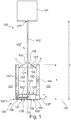
- Fig. 1 shows a sectional view of a rope probe with disc-shaped probe end body 105 according to an exemplary embodiment of the present invention.
- the field device 100 essentially has the three components electronic device 101, measuring cable 102 and probe end device 120. Since the probe-end device 120 has a predeterminable mass, the probe-end device 120 can also be referred to as a gravity-weight 120, weight-body 120 or centering weight 120.
- the gravitational weight 120 could also have only the probe end body 105 or the cable guide 105 to perform its function of graining and / or guiding the rope end.
- the gravitational weight 120 off Fig. 1 has in addition to the cable guide 105, the cable centering 103 or centering device 103 and the centering sleeve 104 or spacing device 104.
- the cable guide 105 or the probe end body 105 is made of a different material than the spacer 104, which is arranged as a cylinder perpendicular to the cable guide 105.
- the measuring cable 102 can essentially be divided into three sections, with the measuring cable 102 itself being manufactured substantially in one piece or monolithically, for example as a wire cable. Thus, the three sections are to be considered as labels only, whereas the measuring cable 102 is free from physical interruptions along a longitudinal axis of the measuring cable 102.
- the first cable section 102 ' is the section between the electronic device 101 and the cable centering device 103.
- the second cable section 102 "runs essentially in a cavity formed by the cable centering 103 and the centering sleeve 4 and the cable guide 105, which belongs to the surroundings 123 of the cable guide 105 and can be filled at least partially with filling material
- Cable section 102 '''or Meßseilendabêt 102''' extends substantially completely in the interior of the cable guide 105.
- a cavity 121 is formed in the interior of the cable guide 105, the extends from the receiving opening 122 on a first surface 105 'of the cable guide 105 to the cable fixation 106 or fastening device 106.
- the course of the measuring cable is determined by the shape of the wall 135, 135 '.
- the wall 135, 135' supports substantially the entire course of Meßseilendabitess 102 '''. If a cable fixation 106 is present in the probe end body 105, the third cable section 102 '''extends from the receiving opening 122 to the cable fixation 106.
- the wall 135, 135' adjoins directly to the receiving opening 122 and can therefore be used as a wall of the Receiving opening 122 are considered.
- the measuring cable 102 is L-shaped.
- the third cable section 102 ''' has a kink 129.
- the line section 102 ''' substantially completely parallel to the lateral surface of the centering sleeve 104 to the second surface 105 ", the lower surface 105" or the boundary 105 "of the probe body 105 would run a long extension of the third cable section 102 '''can be achieved by the L-shaped configuration, without this end section 102''' an in Fig. 1 not shown container bottom touched.
- the L-shape of the measuring cable is achieved by kinking a portion of the end portion 102 '''.
- the kink 129 makes the measuring cable 102 deviate from the direction of gravity, which in Fig.1
- This bend 129 can be achieved by a correspondingly shaped wall 135.
- the thickness d would represent the maximum length of the end portion 102 '''in a purely vertical course of the measuring cable, in particular, when the receiving opening 122 is disposed at the thickest portion of the cable guide 105.
- the probe end body 105 has a receiving opening 122 for the end 102 '''of the measuring cable 102, through which the cable end 102''' can be inserted into the cavity 121.
- the cavity By inserting the cavity is substantially sealed against an environment 123, so that no material or matter from the environment 123 can penetrate into the interior 121 of the cable guide 105.
- this environment 123 may have a filling material when the measuring device 100 is installed in a product container.
- a porous or permeable configuration of at least one device selected from the centering device 103, the spacing device 104 and the probe end body 105 it is also possible for the contents to be filled in the Fig. 1 penetrate inside the spacer 104 and thus reach the measuring cable 102 in the area of the second cable section 102 ".
- the filling material in the second cable section 102 can "get to the measuring cable 102"
- a measurement can take place not only in the outer region of the probe weight 120, ie in the uppermost cable section 102 ', but already inside the probe weight 120, ie in the region of middle cable section 102 " Container bottom in Fig. 1 is not shown, up to the position at which the measuring cable 102 can come into contact with the contents earliest.
- this thickness d is smaller than the height s of the weight body 120.
- the height d can also be made very small, since due to the kink in the measuring cable, a cable end 106 far from the second cable section 102 "so as to reduce interference of the cable end. Further, since the probe bottom 105" or the lower boundary 105 "is designed to be very close to the tank bottom, the dead zone becomes Measuring probe essentially determined by the thickness d of the cable guide 105.
- the wall 135, 135 ' not only separates the end portion 102' '' of the measuring cable from the probe bottom 105 'but also the lateral boundary 105' '' In the case of a cylindrical probe body, the lateral boundary 105 '' 'is the circumferential cylindrical surface of the probe end body 105. In general, the wall 135, 135 'separates the end section 102' '' of the measuring cable from the lateral surface 105 ', 105', 105 ''' 'of the probe end body 105.
- the Seilzentri für 103 is made of plastic, such as PTFE, PP, PE, PEEK, ceramic, and has a low-reflection shape.
- a low-reflection form means that the value of an S-parameter is small, which indicates a measure of the false echo, which is caused due to the discontinuity formed by the rope centering.
- a low-reflection shape ie, a shape that results in only small reflections, may be a triangular-sectioned shape, as in FIG Fig. 1 shown.
- the triangular cross section of the rotationally symmetrical cone has an angle of inclination ⁇ between the legs 124 and 125 and between the legs 124 and 126, respectively.
- the cross section of the centering device 103 has acute angles ⁇ .
- the angle directed in the direction of the spacer 104 may for example be 30 ° or 45 ° or in the range of 30 degrees to 45 degrees.
- the cable centering 103 is partially disposed in the interior of the centering sleeve 104. The tips of the angles between the base line 124 or base 124 of the cable centering 103 and the leg 125 or the leg 126 in this case bears against the inner wall of the centering sleeve 104, which is designed as a hollow cylinder.
- the cable centering 103 can be displaced during assembly along the measuring cable 102 like a piston within the centering sleeve 104. After placement of the cable centering 103 at the desired position, which is as close as possible to the electronic device 101 at one end of the centering sleeve 104, the cable centering 103 is fixed to the measuring cable 102 in order to maintain a predeterminable position of the measuring cable.
- the interior of the centering sleeve 104 can be assigned to the environment of the cable guide 105. This interior forms a cavity. Even if the interior of the centering sleeve 104 in Fig. 1 empty and shown as a cavity, the probe weight 120, which has the centering sleeve 104, the cable guide 105 and the cable centering 103, may also be formed as a solid body.
- the cable centering 103 holds the measuring cable 102 in the center of the probe device 120 and thereby makes it more difficult for the measuring cable 102 to come into contact with the centering sleeve 104. This alignment facilitates installation of the probe-end device 120 into a standpipe. A contact of the measuring cable 102 with the standpipe can be prevented.
- the probe end device 120 is arranged rotationally symmetrically or coaxially around the measuring cable 102. An imbalance, which is caused by the bent cable end portion 102 '''is compensated.
- the measuring cable 102 and in particular a longitudinal axis of the measuring cable forms an axis of symmetry for the centering sleeve 104 and / or the cable centering 103 as well as for the outer shape of the cable guide 105.
- the rotationally symmetrical design makes it possible to achieve a uniform weight distribution around a center of gravity of the measuring cable 102.
- the probe end device 120 or probe device 120 essentially has a length s, which is formed by the thickness d of the cable guide 105 and the length of the centering sleeve 104.
- the entire length of the probe end device 120 may, in the case of overhanging the roof-shaped rope centering 103, as in Fig. 1 shown, slightly longer than the length s fail, this length has substantially no influence on the electrical properties of the Weighing Weight 120, which are responsible for the reflection of an electromagnetic wave at an interface in the region of the second Meßseilabsacrificings 102 ".
- the centering sleeve 104 which may be made of metal or plastic, ie either of the same or of a different material as the cable guide 105, serves on the one hand to increase the mass of the probe weight 120 and on the other hand for centering the measuring cable 102, if the cable probe 102, 120 is installed in a standpipe or in a bypass.
- the cable guide 105 and centering sleeve 104 may be integrally made of plastic or metal.
- the cable guide 105 and / or the centering sleeve 104 is / are partially broken in order to allow contents to reach the middle measuring cable section 102 ", the cable guide 105 prevents the measuring cable 102 from coming into contact with the centering sleeve 104 in that it separates the measuring end 102".
- the spacing of the end of the measuring end 102 '"with respect to a reference surface is effected by means of the cable guide 105. 'the cable guide 105th
- the cable guide 105 provides the shape of a course of the end portion 102 '' 'of the measuring cable inside the cable guide 105 and allows a deviation of the course of the rope from a predetermined by gravity sense of action on the measuring cable 102 in the direction of the longitudinal axis of the measuring cable 102nd As a result of this deviation, the shape of which can be predetermined by the extent of the cavity 121 in the interior of the probe body 105, at least one bend 129 can be introduced into the measuring cable 102, which can ensure that the total length of the measuring cable 102 can extend beyond the probe length 1 ,
- the probe length 1 extends from the coupling device 127, with which the measuring cable 102 can be attached to the electronic device 101, to the lower surface 105 "of the probe body 105.
- the cable fixation 106 is at an outer or remote end of the measuring cable 102 in the region of the third Cable section 102 '' 'arranged and can serve to secure the measuring cable inside the probe body 105.
- the cable fixation 106 or fastening means 106 may in addition to acting from the receiving opening 122 and / or from the hollow body 121 on the measuring cable 102 pressing force as a backup in front of a Slipping out of the cable from the probe body 105 serve.
- the kink 129 is designed so that it can be passed by an electromagnetic wave as free of reflections. Due to the kink 129, the volume of the cavity 121 is greater than the volume that would extend longitudinally along the measuring cable from the receiving opening 122 to the lower surface 105 "or to the limit 105" of the probe end body 105 when the measuring cable 102 along the gravity or vertically along the longitudinal direction over the entire thickness d of the probe body in the probe body 105 would be inserted.
- the boundary 105 "or the bottom surface 105" of the probe body forms a baseline 128 or reference line 128, from which the thickness of the probe body d, the length s of the probe weight 120 and the length 1 of the rope probe is measured.
- the kink 129 is the total length of the Measuring cable 102 longer than the probe length 1, whereby an artificial extension of the probe length 1 can be achieved.
- Fig. 2 shows a sectional view of a U-shaped probe body 105a or a barrel-shaped probe body 105a.
- the structure of the field device 100a substantially corresponds to the structure of the field device 100 Fig. 1
- Fig. 1 shows a disk-shaped probe body 105
- Fig. 2 a barrel-shaped probe-end body 105a formed with a U-shaped cross section.
- the probe end body 105a is not as shown in FIG Fig. 1 shown, one made of a separate material or made as a separate part centering sleeve 104, but that the centering sleeve is part of the probe body 105a.
- the third cable portion 102a ''' may be U-shaped, and follow from the receiving opening 122a of the wall of the probe end body 105a.
- the probe weight 120a or the probe-end device 120a substantially comprises the probe-end body 105a and the cable centering 103a.
- the interior of the probe weight 120a is empty or hollow, so that a filling projecting beyond the surface 105a 'can pass through openings in the barrel-shaped probe body 105a to the second cable portion 102a "of the measuring cord 102a to obtain a useful echo or level echo in the second
- the cable centering 103a is as well as in FIG Fig. 1 shown formed with triangular cross-section low reflection.
- the fastening device 106a is formed in a side wall of the barrel-shaped probe body 105a.
- the third cable section 102a ''' is guided in the cavity 121a, which is U-shaped, resulting in the U-shape of the end portion of the measuring cable 102a. Since the exterior of the probe body 105a or the probe end body 105a is rotationally symmetrical, with appropriate shaping of the cavity 121a in the interior of the probe end body 105a, the cable end 102a '''still extend in other areas of the probe body 105a to increase the distance between the receiving opening 122a and the cable end in the region of the fastening device 106a.
- the cavity inside the probe body 105a is not rotationally symmetric.
- an extension of the distance between the receiving opening 122a and the cable end 106a takes place with respect to an unbent course.
- This extension can increase the distinctness of a false echo caused by the cable end from a useful echo, which is caused by a filling level in the region of the second cable section 102a ", without the distance from a lower surface 105a" of the probe body 105a with respect to a in Fig. 2 not shown bottom surface of a container to enlarge.
- a dead zone is determined substantially by the thickness d of the probe body 105a, that is, the distance between the upper surface 105a 'and the lower surface 105a.
- the probe body 105a is entirely made of plastic so that metallic parts of a centering sleeve 104 as shown in FIG Fig. 1 represented, can be omitted.
- the outer diameter of the tightening weight 120a which is essentially determined by the cylindrical surfaces of the probe body 105a parallel to the second cable section 102a ", can be reduced because of the risk of contact of the measuring cable
- small straightening weights 120a can be realized, and the wall 135a can also provide spacing of the fairing end 102a '''from the lateral surface 105a''' which is parallel to a longitudinal axis of the probe-end device 120a.
- the Fig. 3 shows a sectional view of the field device 100 from Fig. 1 in a container 308 together with an echo curve 320 according to an exemplary embodiment of the present invention.
- the probe weight 120 is in the Interior of the container 308 and immersed in the filling 310, which is located in the container 308 in the region of a bottom surface 321 of the container 308.
- the filling material 310 reaches the surroundings of the probe end body 105 and the measuring cable 102 in the region of the second cable section 102 " Container 308, a boundary layer 309 or a filling level 309.
- the two different materials are the product 310 and the atmosphere of air.
- the boundary layer 309 leads to a reflection of the electromagnetic wave traveling along the measurement cable 102, which propagates from the electronics device 101 in the direction of the container bottom 321. It is the Fig. 1 It can be seen that the container height h, which extends from the container bottom 321 into the region of a container opening and into the region of a coupling device 127, at which the electronic device 101 is connected to the measuring cable 102, is insignificantly greater than the probe length 1, which from the coupling device 127 to the boundary surface 105 "extends.
- an echo curve 320 is shown in order to clarify striking points of the echo curve in relation to their physical causes in the measuring arrangement.
- the time axis corresponds to a distance of the traveling electromagnetic wave along the measuring cable 102, ie the time t can be converted into a physical distance and vice versa.
- the field device 100, measuring device 100, the measuring device 100 or the sensor 100 is installed in the container 308, so that the measuring cable 102 and the measuring weight 120 are inside the container 308 and so that the electronic device 101 is arranged in the exterior of the container 108.
- a mounting flange can be used which in Fig. 3 not shown.
- the filling material 310 is generally not electrically conductive, which leads to strong reflections if an electromagnetic wave tries to penetrate into the filling material 310.
- the sensor electronics 101 or electronic device 101 sends an electromagnetic pulse 312 in the direction of the filling material 310.
- This electromagnetic pulse has a certain pulse width as a function of the transit time and the pulse duration, which leads to a pulse shape along a time axis t. Due to the pulse width, there may be an overlap of echoes.
- the pulse width is also responsible for ensuring that echoes produced by this pulse have a certain pulse width.
- the amplitude of the reflections depends on the characteristic of an impurity, in particular on the reflection properties of the impurity.
- the electromagnetic pulse 312 propagates in the direction of the filling material 310 and strikes the low-reflection cable centering system 103 after passing through the first section 102 ' Fig. 3 illustrated fill level of the filling material 310, which is in the region of the second cable section 102 ", inside the probe weight 120, the first cable section 102 'is completely free of contents, resulting in a substantially undisturbed propagation of the transmission pulse up to the cable centering 103. Due to the optimized shape and material selection, ie the low-reflection shape and the low-reflection material, the cable centering 103 causes only a very low interference echo, as can be recognized by the low amplitude of the echo 313.
- the influence of an echo is shown by the ratio of the amplitude of the echo
- the low amplitude of the clutter 313 relates to the amplitude of the transmit pulse 312.
- the amplitude is represented in the echo curve 320 perpendicular to the time axis t compared to the emitted pulse 312.
- the impulse propagating in the direction of filling material 310 reaches the boundary layer 309 or the product surface 309 in the second cable region 102.
- the product 309 is made of essentially non-conductive material, for example, the product is Oil
- the amplitude of the Greechos 314 is substantially greater than the amplitude of
- the level echo 314 can be well distinguished from the small clutter 313 caused by the rope centering 103, and the level can be determined with high accuracy.
- Another false echo 316 which influences the recognizability of the level echo, d. H. of the useful echo 314 is the end echo 316 produced by the cable end in the region of the fastening device 106 of the measuring cable 102. This arises at the distal end of the measuring cable 102 in the direction of propagation of the electromagnetic wave, ie where the measuring cable ends physically and into another Material passes over.
- This echo can be seen as a rope end echoes 316, since the amplitude is in the opposite direction as the false echo 313 and the useful echo 314. The position is dependent on the distance between the receiving opening 122 and the cable end in the region of the attachment 106.
- the false echo 316 would be pushed along the time axis t in the direction of the useful echo 314 and, at a low filling level f, would lead to a superposition of the false echo 316 with the useful echo 314.
- This superimposition At a low level, a dead zone would result in a certain range of the level f
- the dead zone is an area in which unusable measuring results are generated and which is determined by the distance between the end of the measuring rope and the level f.
- This local distance can also be mapped or projected onto the time axis of the echo curve 320. Extending the physical distance of the clutter 316 and true echo 314 causes the physical distance and the effect of the clutter 316 on the level echo 314 can be reduced or avoided. Thus, the level echo can be determined 314 with a high measurement accuracy for determining the level 314. Consequently, when using the probe end device 120 according to the invention, it is also possible to determine a filling level 309, f, which is located near the area of the bottom surface 321.
- Fig. 4 shows a cross-sectional view of a measurement setup with a field device 100 from Fig. 1 and a standpipe 411 according to an exemplary embodiment of the present invention.
- the measuring probe of the field device 100 is embedded in a container 408 with a standpipe 411. Since the same probe 102, 120 as out Fig. 1 and Fig. 3 the total length of the probe 1 also corresponds to the probe length 1 Fig. 1 and Fig. 3 ,
- the container height h ' results from the height of the container 408 and a portion of the length of the standpipe 411. The height h' is related to the container bottom 421.
- the level height 409 of the filling material 410 is also referred to the container bottom 421 and referred to as f '.
- the probe length 1 or the probe end 415 is determined by the lower surface 105 "of the weight body 120 and extends to the coupling device 127, at which the electronic device 101 is connected to the measuring cable 102.
- the electronics device 101 generates the electromagnetic pulse 412.
- the cable probe 102, 120 with the measuring cable 102 and the probe weight 120 is mounted inside the standpipe 411, so that the centering sleeve 104 and the cylindrical wall of the standpipe 411 extend coaxially with the measuring cable 102.
- the centering sleeve 104 in combination with the cable centering 103, ensures that the measuring cable 102 is kept or distanced from the wall of the standpipe 411 over its entire course in the interior of the standpipe 411.
- the standpipe 411 is open in the direction of the bottom 421, so that the probe weight 120 can exit in the direction of the container bottom 421 from the standpipe 411.
- the probe weight 120 is located largely in the standpipe 411.
- the electrically non-conductive filling material 410 is filled, the filling level 409 to be determined.
- the centering sleeve 104 ensures that the measuring cable 102 is substantially in the center, d. H. along a longitudinal axis, which is predetermined by the measuring cable 102, is positioned within the standpipe 411.
- the centering sleeve 104 prevents by the central centering and / or by holding the measuring cable in a predetermined position, that it can lead to a short circuit between the measuring cable 102 and the standpipe 411.
- the centering sleeve 104 ensures in the standpipe 411, which is spaced from the container bottom 421, that a measurement of the filling material 410 can also take place in the intermediate space between the standpipe end and the probe end 415.
- the electromagnetic pulse 412 is sent along the measuring cable 102 in the direction of the probe end 105 ", 415.
- This transmitting pulse 412 is shown in the echo curve 420.
- the cable centering 103 generates a small interference echo 413.
- the transition between the different materials in the container interior and The filling material 410 at the boundary layer 409 provides the level echo 414.
- This level echo 414 is near the region of the probe end 105 ", 415. If the measuring cable only reached the limit 105", ie, up to the physical probe end 415, the negative probe echo 416 would form in the region of the probe echo 415 and be superposed with the useful echo 414.
- the interference echo 416 By the artificial extension by means of the L-shaped bend of the measuring cable 102, however, it is possible to displace the interference echo 416 into a region of the time axis t of the echo curve 420, which corresponds to the probe end 415 corresponding to a more advanced time t, whereby there is no overlapping or only a slight overlay of the wanted echo 414 and the clutter 416 comes. Due to the kink, the true echo 414 and the interference echo 416 are widely spaced.
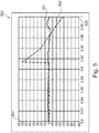
- Fig. 5 shows a quality measurement curve for a rope probe according to an exemplary embodiment of the present invention.
- the measurement curves 501, 502 represent the deviation of an amplitude value of an echo curve from a nominal value in millimeters along a measured distance.
- the abscissa 503 shows the distance values in meters from 0.8 m to 1 m. These distance values can be converted into time values t of the echo curve.
- the ordinate 504 shows the deviations from a nominal value in millimeters.
- the graph 500 represents the measurement errors in a measurement in the oil, in particular in mineral oil, so in an oil-filled container and compares the deviation of a setpoint with those of probes with a massive gravity weight.
- the curve 501 belongs to a measurement, which with the rope probe according to the invention according to Fig. 1 is included.
- the measurement curve 502 belongs to a rope probe with a massive probe weight and undisturbed cable length.
- the distance value plotted on the abscissa 503 determines the distance of the interface 309, 409 from the coupling device 127.
- the tensioning weight 120 with the construction according to the invention serves to keep the measuring cable 102 taut without producing relevant false echoes due to the tensioning weight.
- This rope weight straining weight 120 generates only small clutter in a region near the container bottom or far from the coupling device.
- the low false echoes make it possible to measure products with a low DK value in the area of the probe weight without blocking distance with high accuracy.
- filled goods with a low-DK value ie with a low DK value
- Oil, especially mineral oil is an electrically poorly conductive material that produces strong reflections.
- Rope probes with massively constructed tension weights or massively constructed centering weights can have a blocking distance of more than 100 mm. This means that a measurement of the container level in the range of less than 100 mm with such a rope probe is not possible. In other words, this may mean that with a rope probe with solid probe weight and / or with unverlyrtem fair part 102, a level height f, f can be determined only from 100 mm, since only from a length of 100 mm between level and end of the rope 106 the Endeeocho
- the probe end body 105, 105a according to the invention which can be used for the isolated extension of a measuring cable end section, allows a blocking distance of less than 100 mm.
- the container volume can be well utilized by the probe by bringing the probe tip 105 ", 105a" close to the container bottom.
- the curve 502 in the direction of decreasing distance values to the coupling-in device shows a rectilinear course with a small measuring error of 0 mm.
- the according to the invention with the probe according to Fig. 1 Measured in the mineral oil measured curve 501 a rectilinear and thus substantially error-free course up to a distance value of about 990 mm. For this reason, with the measuring probe belonging to the curve 501 according to Fig. 1 a good determination of a filling height from a filling height f, f 'of 10 mm be possible.
- Fig. 5 shows with curve 502 the measurement error of a 1 m long rope probe installed in an oil tank.
- the standard centering weight was compared with a probe weight according to the invention according to FIG Fig. 1 ,
- Fig. 6 shows a cross-sectional view of another rope probe 600 according to an exemplary embodiment of the present invention.
- Fig. 6 is the electronic device that can be connected to the coupling device 627, not shown.
- Fig. 6 only shows the measuring cable 602 and the probe weight 620.
- the probe weight 620 and the measuring cable 602 extend partially in the downwardly open standpipe 611.
- the probe weight 620 has the cable guide 605, the Rope centering 603 and the centering sleeve 604 on. Not to be seen in Fig. 6 the inside of the cable guide 605 extended course of the cable end portion of the measuring cable 602. Both the cable guide 605 and the cable centering 603 are disc-shaped.
- the centering sleeve 604 is designed as a cylinder open on both sides, which is delimited by the disk-shaped cable centering 603 and the disk-shaped cable guide 605. Both the cable guide 605 and the cable centering 603 and the centering sleeve 604 have openings so that filling material can penetrate into the interior of the cable weight 620. Due to the penetration of the filling material, a level can be determined with the measuring cable 602 above the cable guide 605.
- the cable centering 603 is designed as a plastic web for centering the measuring cable 602
- the cable guide 605 is also designed as a plastic web for rope centering and cable attachment Fig. 6
- extended end portion of the measuring cable 602 is isolated by means of the cable guide 605 of the surrounding medium or the surrounding environment, but the contents can penetrate into the interior 623 of the gravity weight 620.
- Fig. 7 shows a detail of the tightening weight 620 Fig. 6 according to an exemplary embodiment of the present invention.
- the measuring cable 602 is made of wire mesh and has a substantially over the entire length of a circular diameter of 1.5 mm. Accordingly, the cable feedthrough in the plastic web 603 or in the cable centering 603 is formed with a corresponding diameter. Likewise, the receiving opening 622 has a circular diameter of 1.5 mm.
- the width r of the probe body 605 is 25 mm and the total width R of the penalty weight 620 including centering sleeve 604 is 35 mm.
- the total length s of the tightening weight 620 is 72 mm and the thickness s ", d of the probe body 605 is 8 mm
- Fig. 8 shows a field device 800 with the electronic device 601, the coupling device 801, a mounting flange 802, the standpipe 611 and the gravity weight 620, which at one of the coupling device 801 opposite end of the standpipe 611 exits the standpipe.
- the trade fair section 602 will be in Fig. 8 obscured by the standpipe 611.
- the length m of the standpipe is 980 mm, so that the gravity weight 620 20 mm protrudes from the standpipe 611.
- Fig. 8 also shows the electronic device 601 of a two-wire device.
- the electronic device 601 has at least one electronic connection 803, to which a two-wire line can be attached.
- This two-wire line can be used both for power supply and for data transmission of the electronic device 601.
- a 4 ... 20 mA signal is transmitted via the two-wire cable
- a HART signal is transmitted via the two-wire cable.
- Fig. 9 shows a side view of the field device 800 Fig. 8 , In the figure, the electronic device 601, the coupling device 801, the flange 802, the measuring cable 602 and the gravity weight 620 are illustrated. By gravity caused by the probe weight 620, the measuring cable 620 is tightened. There the standpipe 611 in Fig. 9 is omitted, the measuring cable 602 between the electronic device 601 and the gravity weight 620 can be seen.
- Fig. 10 shows a sectional view of the field device 800 Fig. 8 , wherein also the electronic device 601, the coupling device 801, the flange 802, the measuring cable 602, the standpipe 611 and the gravity weight 620 can be seen.
- FIG. 12 shows a flowchart for a method of manufacturing a probe device according to an exemplary embodiment of the present invention.
- a probe end body takes place in step S1200.
- a receiving opening for insertion of an end of a measuring cord into the probe body is made, and in step S1400 forming a wall 135, 135 'of the receiving opening 122 and / or the probe-end body 105 to form a Course of the inserted into the receiving opening 122 Meßseilendabterrorisms 102 '' 'or a Meßseilendabterrorisms 102' ' pretend.
- the shaping of the wall 135, 135 ' takes place in such a way that it spaces the measuring cable end section 102 "' inserted into the receiving opening 122 from at least one boundary 105 ', 105", 105 "', 105" 'of the probe end body 105.
- step S1500 ends in step S1500.
- the wall may be formed into a cavity 121 in the probe body 105 that adjoins the receiving opening 122.
- the adaptation of the receiving opening 122 to the cross-section of the measuring cable 102 is such that the receiving opening can be closed with the measuring cable, so that the cavity 121 can be separated from an environment is when the measuring cable is inserted into the cavity.
- the measuring cable prevents a filling material from penetrating into the interior of a probe body.
- a length of the cavity is formed such that the length is greater than the length corresponding to the perpendicular distance d, s "from the receiving opening to an opposing boundary of the probe-end body, which boundary is established, opposite the cavity Essentially, the separation of the cavity substantially prevents filling material from entering the cavity or from a measuring rope inserted into the cavity, however, the probe body may be shaped such that the probe body serves as insulation for the measuring cable, however the contents can penetrate into the interior of a gravity weight.
- a volume of the cavity is formed such that the volume is greater than the volume of a comparable cylinder having a base area which corresponds to the cross section of the receiving opening and has a length which is the vertical distance d , s "from the receiving opening to an opposing boundary of the probe body corresponds.
Landscapes
- Physics & Mathematics (AREA)
- Radar, Positioning & Navigation (AREA)
- Remote Sensing (AREA)
- Engineering & Computer Science (AREA)
- General Physics & Mathematics (AREA)
- Electromagnetism (AREA)
- Fluid Mechanics (AREA)
- Computer Networks & Wireless Communication (AREA)
- Thermal Sciences (AREA)
- Measurement Of Levels Of Liquids Or Fluent Solid Materials (AREA)
- Investigating Or Analyzing Materials By The Use Of Ultrasonic Waves (AREA)
- Length-Measuring Devices Using Wave Or Particle Radiation (AREA)
- A Measuring Device Byusing Mechanical Method (AREA)
Claims (13)
- Sonde à câble, réalisée pour un appareil de mesure de remplissage (101), comportant :un câble de mesure (102) comportant une section pouvant être prédéfinie, lequel est réalisé pour guider une onde radar ou une micro-onde ;un dispositif sondeur (120), comportant :un corps sondeur (105) doté d'une ouverture de logement (122), dans laquelle un tronçon terminal (102''') du câble de mesure (102) est inséré dans l'ouverture de logement (122) ;dans laquelle l'ouverture de logement (122) comporte une paroi (135, 135'), laquelle est arrangée pour définir un parcours du tronçon terminal (102''') du câble de mesure inséré dans l'ouverture de logement (122) ; etdans laquelle la paroi (135, 135') est en outre arrangée pour écarter le tronçon terminal (102''') du câble de mesure inséré dans l'ouverture de logement (122) d'au moins une délimitation (105', 105'', 105''', 105'''') du corps sondeur ;dans laquelle la paroi (135, 135') forme une cavité (121) à l'intérieur du corps sondeur (105), laquelle se rattache à l'ouverture de logement (122) ; caractérisée en ce que la cavité (121) est conçue en forme de L, en forme de U et/ou hélicoïdale, de sorte que la cavité (121) présente une longueur, laquelle est supérieure à l'écart vertical de l'ouverture de logement (122) à une délimitation (105'') du corps sondeur (105) agencée en opposition à l'ouverture de logement (122).
- Sonde à câble selon la revendication 1,
dans laquelle l'ouverture de logement (122) est adaptée à la section du câble de mesure (102) de telle sorte que l'ouverture de logement (122) peut être fermée par le câble de mesure (102), de sorte que la cavité (121) est séparable par rapport à un environnement (123), lorsque le câble de mesure (102) est inséré dans la cavité ; et
dans laquelle la délimitation (105") est arrangée pour séparer essentiellement la cavité (121) par rapport à un environnement (123). - Sonde à câble selon la revendication 1 ou 2, dans laquelle le corps sondeur (105), la paroi (135, 135') et/ou la cavité (121) sont arrangés de telle sorte qu'une forme de parcours du tronçon terminal (102''') inséré du câble de mesure (102) peut être définie par leur biais.
- Sonde à câble selon l'une des revendications 1 à 3, dans laquelle la cavité (121) possède la section et la longueur de l'ouverture de logement (122) ; et
dans laquelle la section de la cavité (121) correspond à la section de l'ouverture de logement (122) sur toute la longueur. - Sonde à câble selon l'une des revendications 1 à 4, dans laquelle le corps sondeur (105) est fabriqué en plastique et/ou en métal.
- Sonde à câble selon l'une des revendications 1 à 5, dans laquelle la paroi (135, 135') et/ou la cavité (121) présente un dispositif de fixation (106) pour l'extrémité du câble de mesure.
- Sonde à câble selon l'une des revendications 1 à 6, dans laquelle le corps sondeur (105) comporte un dispositif de centrage (103) et/ou un dispositif écarteur (104) ;
dans laquelle le dispositif de centrage (103) et/ou le dispositif écarteur (104) sont arrangés pour maintenir dans une position prédéfinie un câble de mesure (102) inséré dans le corps sondeur (105). - Sonde à câble selon l'une des revendications 1 à 7, dans laquelle le corps sondeur (105) et/ou le dispositif de centrage (103) sont conçus en forme de disque, de barillet, d'étoile et/ou de roue à rayons.
- Sonde à câble selon l'une des revendications précédentes, dans laquelle la sonde à câble est arrangée pour l'utilisation dans un conteneur (308, 411) doté d'une hauteur de conteneur (h, h') pouvant être prédéfinie ;
dans laquelle le câble de mesure (102) possède une longueur supérieure à la hauteur de conteneur (h, h') pouvant être prédéfinie et/ou supérieure à une longueur de sonde (l) pouvant être prédéfinie. - Sonde à câble selon l'une des revendications précédentes, dans laquelle le câble de mesure (102) comporte une deuxième extrémité ;
dans laquelle la deuxième extrémité comporte un dispositif de couplage (127) pour une onde électromagnétique (312, 412). - Appareil de mesure de remplissage (100, 100a, 800), comportant :un dispositif électronique (101, 601) ;une sonde à câble selon l'une des revendications précédentes ;dans lequel le dispositif électronique (101, 601) est connecté au câble de mesure (102, 102', 602') ;dans lequel le dispositif électronique (101, 601) est conçu pour émettre et/ou recevoir une onde électromagnétique (312, 412).
- Appareil de mesure de remplissage (100, 100a, 800) selon la revendication 11, dans lequel l'appareil de terrain (100, 100a, 800) est conçu comme appareil de terrain à deux conducteurs.
- Procédé de fabrication d'une sonde à câble dotée d'un dispositif sondeur (120) et d'un câble de mesure (102) selon l'une des revendications 1 à 10, comportant :la préparation d'un corps sondeur (105) ;la création d'une ouverture de logement (122) pour l'insertion d'une extrémité de câble de mesure (102) dans le corps sondeur (105) ;la formation d'une paroi (135, 135') de l'ouverture de logement (122) de sorte que celle peut définir un parcours du tronçon terminal (102''') du câble de mesure inséré dans l'ouverture de logement (122) ; etla formation de la paroi (135, 135') de sorte qu'elle écarte le tronçon terminal (102''') du câble de mesure (102) inséré dans l'ouverture de logement (122) d'au moins une délimitation (105', 105'', 105''', 105'''') du corps sondeur (105) ; etl'insertion du tronçon terminal (102''') du câble de mesure (102) dans l'ouverture de logement (122).
Applications Claiming Priority (1)
| Application Number | Priority Date | Filing Date | Title |
|---|---|---|---|
| DE102015220578.9A DE102015220578A1 (de) | 2015-10-21 | 2015-10-21 | Sondenendvorrichtung und Verfahren zum Herstellen einer Sondenendvorrichtung |
Publications (2)
| Publication Number | Publication Date |
|---|---|
| EP3159662A1 EP3159662A1 (fr) | 2017-04-26 |
| EP3159662B1 true EP3159662B1 (fr) | 2019-09-11 |
Family
ID=57137830
Family Applications (1)
| Application Number | Title | Priority Date | Filing Date |
|---|---|---|---|
| EP16191918.8A Active EP3159662B1 (fr) | 2015-10-21 | 2016-09-30 | Sonde à corde, détecteur de niveau et procédé de fabrication d'une sonde à corde |
Country Status (4)
| Country | Link |
|---|---|
| US (1) | US10386220B2 (fr) |
| EP (1) | EP3159662B1 (fr) |
| CN (1) | CN107014463B (fr) |
| DE (1) | DE102015220578A1 (fr) |
Families Citing this family (1)
| Publication number | Priority date | Publication date | Assignee | Title |
|---|---|---|---|---|
| DE102018219366A1 (de) * | 2018-11-13 | 2020-05-14 | Vega Grieshaber Kg | Sensorvorrichtung und Sensorvorrichtungs-Halterung |
Citations (4)
| Publication number | Priority date | Publication date | Assignee | Title |
|---|---|---|---|---|
| US3319514A (en) * | 1962-06-13 | 1967-05-16 | Jr Decker G Mcallister | Submersible turbidity detector unit |
| DE2401486A1 (de) * | 1973-01-15 | 1974-07-18 | Bindicator Co | Schuetthoehe-anzeigegeraet |
| WO2004042333A1 (fr) * | 2002-11-08 | 2004-05-21 | Endress + Hauser Gmbh + Co. Kg | Dispositif servant a tendre un cable d'un limnimetre et procede correspondant |
| DE102005015548A1 (de) * | 2005-04-04 | 2006-10-05 | Endress + Hauser Gmbh + Co. Kg | Vorrichtung zur Bestimmung und/oder Überwachung des Füllstandes eines Mediums |
Family Cites Families (15)
| Publication number | Priority date | Publication date | Assignee | Title |
|---|---|---|---|---|
| DE9103122U1 (de) * | 1991-03-15 | 1991-07-25 | GDT Software + Electronic GmbH, 5000 Köln | Füllstandssonde |
| DE4224635C2 (de) * | 1992-07-25 | 2000-09-28 | Gestra Gmbh | Sonde zur Überwachung von Medium |
| DE4336494C2 (de) * | 1993-10-26 | 1995-11-02 | Endress Hauser Gmbh Co | Vorrichtung zur Füllstandsmessung in Behältern |
| US5945913A (en) * | 1995-12-26 | 1999-08-31 | Gallagher; Daniel J. | Liquid level alarm system |
| DE59611384D1 (de) | 1996-12-20 | 2006-10-26 | Endress & Hauser Gmbh & Co Kg | Endkapsel für eine Seilsonde |
| GB0004306D0 (en) * | 2000-02-23 | 2000-04-12 | Cambridge Consultants | Time domain reflectometry |
| DE10032775B4 (de) * | 2000-07-06 | 2007-06-14 | Endress + Hauser Gmbh + Co. Kg | Vorrichtung zur Bestimmung und/oder Überwachung des Füllstandes eines Füllguts in einem Behälter |
| DE10045235A1 (de) * | 2000-09-13 | 2002-03-28 | Endress Hauser Gmbh Co | Füllstandsmeßgerät |
| DE102004020896A1 (de) * | 2004-04-28 | 2005-11-17 | Endress + Hauser Gmbh + Co. Kg | Vorrichtung zur Bestimmung und/oder Überwachung einer Prozessgröße |
| US7592946B2 (en) * | 2005-02-14 | 2009-09-22 | Endress + Hauser Gmbh + Co. Kg | Level measurement arrangement |
| US20070205907A1 (en) * | 2006-03-03 | 2007-09-06 | Robertshaw Controls Company | Switch assembly and system for high-level monitoring |
| US8371179B2 (en) * | 2010-10-08 | 2013-02-12 | Endress + Hauser Gmbh + Co., Kg | Measurement arrangement |
| US20140157891A1 (en) * | 2012-12-11 | 2014-06-12 | Benjamin Columbus Price | Feed hopper level indicator |
| HUE039331T2 (hu) | 2013-12-16 | 2018-12-28 | Grieshaber Vega Kg | Súlyeszköz hullámvezetõhöz, egy szondaeszköz és eljárás súlyeszköz gyártására |
| DE102015116273B4 (de) * | 2015-09-25 | 2017-04-20 | Krohne S. A. S. | Sondenhalterung mit Abstandhalter |
-
2015
- 2015-10-21 DE DE102015220578.9A patent/DE102015220578A1/de not_active Withdrawn
-
2016
- 2016-09-30 EP EP16191918.8A patent/EP3159662B1/fr active Active
- 2016-10-20 US US15/299,126 patent/US10386220B2/en active Active
- 2016-10-21 CN CN201610920783.4A patent/CN107014463B/zh active Active
Patent Citations (4)
| Publication number | Priority date | Publication date | Assignee | Title |
|---|---|---|---|---|
| US3319514A (en) * | 1962-06-13 | 1967-05-16 | Jr Decker G Mcallister | Submersible turbidity detector unit |
| DE2401486A1 (de) * | 1973-01-15 | 1974-07-18 | Bindicator Co | Schuetthoehe-anzeigegeraet |
| WO2004042333A1 (fr) * | 2002-11-08 | 2004-05-21 | Endress + Hauser Gmbh + Co. Kg | Dispositif servant a tendre un cable d'un limnimetre et procede correspondant |
| DE102005015548A1 (de) * | 2005-04-04 | 2006-10-05 | Endress + Hauser Gmbh + Co. Kg | Vorrichtung zur Bestimmung und/oder Überwachung des Füllstandes eines Mediums |
Also Published As
| Publication number | Publication date |
|---|---|
| EP3159662A1 (fr) | 2017-04-26 |
| US10386220B2 (en) | 2019-08-20 |
| CN107014463A (zh) | 2017-08-04 |
| CN107014463B (zh) | 2020-08-28 |
| DE102015220578A1 (de) | 2017-04-27 |
| US20170115154A1 (en) | 2017-04-27 |
Similar Documents
| Publication | Publication Date | Title |
|---|---|---|
| EP2652462B1 (fr) | Dispositif de mesure, dispositif de commande et appareil de mesure pour la mesure d'un niveau | |
| EP2223059B1 (fr) | Procédé de mesure du niveau de remplissage | |
| EP2634541B1 (fr) | Procédé de mesure de niveau de remplissage | |
| EP2154495B1 (fr) | Capteur TDR et procédé de mesure | |
| EP2340420B1 (fr) | Appareil de mesure du niveau de remplissage | |
| WO2012013444A1 (fr) | Dispositif et procédé pour sécuriser la fixation du tube, disposé coaxialement autour de la sonde de mesure, d'une unité de sonde de mesure de l'appareil de mesure de niveau de remplissage sur un élément de raccordement au processus | |
| EP1412710A1 (fr) | Procede pour evaluer les signaux de mesure d'un appareil de mesure fonctionnant selon le principe du temps de propagation | |
| DE112006002933T5 (de) | Radarfüllstandmesssystem und Übertragungsleitungssonde für die Verwendung in einem solchen System | |
| DE10032775A1 (de) | Vorrichtung zur Bestimmung und/oder Überwachung des Füllstandes eines Füllguts in einem Behälter | |
| EP3447456B1 (fr) | Appareil de mesure de niveau de remplissage tdr et procédé de fonctionnement d'un appareil de mesure de niveau de remplissage tdr | |
| EP2652465B1 (fr) | Détermination de propriétés de fluide lors de la mesure d'un niveau de remplissage | |
| EP1069649B1 (fr) | Guide d'ondes d'un détecteur de contenu opérant à micro-ondes | |
| DE102020134320A1 (de) | Antenne zur Dielektrizitätswert-Messung | |
| EP2884245A1 (fr) | Dispositif de poids pour un guide d'ondes, dispositif de sonde et procédé de fabrication d'un dispositif de poids | |
| DE102011106568B4 (de) | Schwimmkörper zur Anzeige eines Füllstandes | |
| DE102020134061A1 (de) | Hochfrequenz-basiertes Feldgerät | |
| EP3159662B1 (fr) | Sonde à corde, détecteur de niveau et procédé de fabrication d'une sonde à corde | |
| EP1274973A2 (fr) | Dispositif de determination du niveau de remplissage d'un recipient avec un agent de remplissage | |
| DE10133692A1 (de) | Verfahren und Sensor zur Füllstandsmessung einer Flüssigkeit in einem Behälter | |
| DE202008007989U1 (de) | Abstandshalteelement zur Zentrierung eines inneren Leiters | |
| EP3244176B1 (fr) | Procédé de surveillance d'une jauge de niveau fonctionnant sur le principe du radar et jauge de niveau | |
| DE102020124404A1 (de) | Integriertes Messgerät mit Füll- und/oder Grenzstandsensor und Druckmesszelle sowie Anordnung eines integrierten Messgerätes an einem Behälter | |
| DE102012218574A1 (de) | Sensor | |
| EP2652463A1 (fr) | Dispositif pour la mesure d'une émulsion comportant un tube vertical | |
| DE102016103430B4 (de) | Zeitbereichs-Reflektometrie-Wellenleiterstruktur |
Legal Events
| Date | Code | Title | Description |
|---|---|---|---|
| PUAI | Public reference made under article 153(3) epc to a published international application that has entered the european phase |
Free format text: ORIGINAL CODE: 0009012 |
|
| STAA | Information on the status of an ep patent application or granted ep patent |
Free format text: STATUS: THE APPLICATION HAS BEEN PUBLISHED |
|
| AK | Designated contracting states |
Kind code of ref document: A1 Designated state(s): AL AT BE BG CH CY CZ DE DK EE ES FI FR GB GR HR HU IE IS IT LI LT LU LV MC MK MT NL NO PL PT RO RS SE SI SK SM TR |
|
| AX | Request for extension of the european patent |
Extension state: BA ME |
|
| STAA | Information on the status of an ep patent application or granted ep patent |
Free format text: STATUS: REQUEST FOR EXAMINATION WAS MADE |
|
| 17P | Request for examination filed |
Effective date: 20170926 |
|
| RBV | Designated contracting states (corrected) |
Designated state(s): AL AT BE BG CH CY CZ DE DK EE ES FI FR GB GR HR HU IE IS IT LI LT LU LV MC MK MT NL NO PL PT RO RS SE SI SK SM TR |
|
| STAA | Information on the status of an ep patent application or granted ep patent |
Free format text: STATUS: EXAMINATION IS IN PROGRESS |
|
| 17Q | First examination report despatched |
Effective date: 20180321 |
|
| GRAP | Despatch of communication of intention to grant a patent |
Free format text: ORIGINAL CODE: EPIDOSNIGR1 |
|
| STAA | Information on the status of an ep patent application or granted ep patent |
Free format text: STATUS: GRANT OF PATENT IS INTENDED |
|
| RIC1 | Information provided on ipc code assigned before grant |
Ipc: G01F 23/00 20060101AFI20190305BHEP Ipc: G01S 13/88 20060101ALI20190305BHEP Ipc: G01F 23/284 20060101ALI20190305BHEP Ipc: G01S 13/10 20060101ALI20190305BHEP |
|
| INTG | Intention to grant announced |
Effective date: 20190326 |
|
| GRAS | Grant fee paid |
Free format text: ORIGINAL CODE: EPIDOSNIGR3 |
|
| GRAA | (expected) grant |
Free format text: ORIGINAL CODE: 0009210 |
|
| STAA | Information on the status of an ep patent application or granted ep patent |
Free format text: STATUS: THE PATENT HAS BEEN GRANTED |
|
| AK | Designated contracting states |
Kind code of ref document: B1 Designated state(s): AL AT BE BG CH CY CZ DE DK EE ES FI FR GB GR HR HU IE IS IT LI LT LU LV MC MK MT NL NO PL PT RO RS SE SI SK SM TR |
|
| REG | Reference to a national code |
Ref country code: GB Ref legal event code: FG4D Free format text: NOT ENGLISH |
|
| REG | Reference to a national code |
Ref country code: CH Ref legal event code: EP |
|
| REG | Reference to a national code |
Ref country code: AT Ref legal event code: REF Ref document number: 1179042 Country of ref document: AT Kind code of ref document: T Effective date: 20190915 |
|
| REG | Reference to a national code |
Ref country code: DE Ref legal event code: R096 Ref document number: 502016006532 Country of ref document: DE Ref country code: IE Ref legal event code: FG4D Free format text: LANGUAGE OF EP DOCUMENT: GERMAN |
|
| REG | Reference to a national code |
Ref country code: NL Ref legal event code: MP Effective date: 20190911 |
|
| REG | Reference to a national code |
Ref country code: LT Ref legal event code: MG4D |
|
| PG25 | Lapsed in a contracting state [announced via postgrant information from national office to epo] |
Ref country code: NO Free format text: LAPSE BECAUSE OF FAILURE TO SUBMIT A TRANSLATION OF THE DESCRIPTION OR TO PAY THE FEE WITHIN THE PRESCRIBED TIME-LIMIT Effective date: 20191211 Ref country code: SE Free format text: LAPSE BECAUSE OF FAILURE TO SUBMIT A TRANSLATION OF THE DESCRIPTION OR TO PAY THE FEE WITHIN THE PRESCRIBED TIME-LIMIT Effective date: 20190911 Ref country code: HR Free format text: LAPSE BECAUSE OF FAILURE TO SUBMIT A TRANSLATION OF THE DESCRIPTION OR TO PAY THE FEE WITHIN THE PRESCRIBED TIME-LIMIT Effective date: 20190911 Ref country code: LT Free format text: LAPSE BECAUSE OF FAILURE TO SUBMIT A TRANSLATION OF THE DESCRIPTION OR TO PAY THE FEE WITHIN THE PRESCRIBED TIME-LIMIT Effective date: 20190911 Ref country code: FI Free format text: LAPSE BECAUSE OF FAILURE TO SUBMIT A TRANSLATION OF THE DESCRIPTION OR TO PAY THE FEE WITHIN THE PRESCRIBED TIME-LIMIT Effective date: 20190911 Ref country code: BG Free format text: LAPSE BECAUSE OF FAILURE TO SUBMIT A TRANSLATION OF THE DESCRIPTION OR TO PAY THE FEE WITHIN THE PRESCRIBED TIME-LIMIT Effective date: 20191211 |
|
| PG25 | Lapsed in a contracting state [announced via postgrant information from national office to epo] |
Ref country code: AL Free format text: LAPSE BECAUSE OF FAILURE TO SUBMIT A TRANSLATION OF THE DESCRIPTION OR TO PAY THE FEE WITHIN THE PRESCRIBED TIME-LIMIT Effective date: 20190911 Ref country code: LV Free format text: LAPSE BECAUSE OF FAILURE TO SUBMIT A TRANSLATION OF THE DESCRIPTION OR TO PAY THE FEE WITHIN THE PRESCRIBED TIME-LIMIT Effective date: 20190911 Ref country code: ES Free format text: LAPSE BECAUSE OF FAILURE TO SUBMIT A TRANSLATION OF THE DESCRIPTION OR TO PAY THE FEE WITHIN THE PRESCRIBED TIME-LIMIT Effective date: 20190911 Ref country code: GR Free format text: LAPSE BECAUSE OF FAILURE TO SUBMIT A TRANSLATION OF THE DESCRIPTION OR TO PAY THE FEE WITHIN THE PRESCRIBED TIME-LIMIT Effective date: 20191212 Ref country code: RS Free format text: LAPSE BECAUSE OF FAILURE TO SUBMIT A TRANSLATION OF THE DESCRIPTION OR TO PAY THE FEE WITHIN THE PRESCRIBED TIME-LIMIT Effective date: 20190911 |
|
| PG25 | Lapsed in a contracting state [announced via postgrant information from national office to epo] |
Ref country code: PT Free format text: LAPSE BECAUSE OF FAILURE TO SUBMIT A TRANSLATION OF THE DESCRIPTION OR TO PAY THE FEE WITHIN THE PRESCRIBED TIME-LIMIT Effective date: 20200113 Ref country code: IT Free format text: LAPSE BECAUSE OF FAILURE TO SUBMIT A TRANSLATION OF THE DESCRIPTION OR TO PAY THE FEE WITHIN THE PRESCRIBED TIME-LIMIT Effective date: 20190911 Ref country code: NL Free format text: LAPSE BECAUSE OF FAILURE TO SUBMIT A TRANSLATION OF THE DESCRIPTION OR TO PAY THE FEE WITHIN THE PRESCRIBED TIME-LIMIT Effective date: 20190911 Ref country code: RO Free format text: LAPSE BECAUSE OF FAILURE TO SUBMIT A TRANSLATION OF THE DESCRIPTION OR TO PAY THE FEE WITHIN THE PRESCRIBED TIME-LIMIT Effective date: 20190911 Ref country code: PL Free format text: LAPSE BECAUSE OF FAILURE TO SUBMIT A TRANSLATION OF THE DESCRIPTION OR TO PAY THE FEE WITHIN THE PRESCRIBED TIME-LIMIT Effective date: 20190911 Ref country code: EE Free format text: LAPSE BECAUSE OF FAILURE TO SUBMIT A TRANSLATION OF THE DESCRIPTION OR TO PAY THE FEE WITHIN THE PRESCRIBED TIME-LIMIT Effective date: 20190911 |
|
| PG25 | Lapsed in a contracting state [announced via postgrant information from national office to epo] |
Ref country code: IS Free format text: LAPSE BECAUSE OF FAILURE TO SUBMIT A TRANSLATION OF THE DESCRIPTION OR TO PAY THE FEE WITHIN THE PRESCRIBED TIME-LIMIT Effective date: 20200224 Ref country code: SM Free format text: LAPSE BECAUSE OF FAILURE TO SUBMIT A TRANSLATION OF THE DESCRIPTION OR TO PAY THE FEE WITHIN THE PRESCRIBED TIME-LIMIT Effective date: 20190911 Ref country code: SK Free format text: LAPSE BECAUSE OF FAILURE TO SUBMIT A TRANSLATION OF THE DESCRIPTION OR TO PAY THE FEE WITHIN THE PRESCRIBED TIME-LIMIT Effective date: 20190911 Ref country code: CZ Free format text: LAPSE BECAUSE OF FAILURE TO SUBMIT A TRANSLATION OF THE DESCRIPTION OR TO PAY THE FEE WITHIN THE PRESCRIBED TIME-LIMIT Effective date: 20190911 |
|
| REG | Reference to a national code |
Ref country code: CH Ref legal event code: PL |
|
| REG | Reference to a national code |
Ref country code: DE Ref legal event code: R097 Ref document number: 502016006532 Country of ref document: DE |
|
| PLBE | No opposition filed within time limit |
Free format text: ORIGINAL CODE: 0009261 |
|
| STAA | Information on the status of an ep patent application or granted ep patent |
Free format text: STATUS: NO OPPOSITION FILED WITHIN TIME LIMIT |
|
| PG2D | Information on lapse in contracting state deleted |
Ref country code: IS |
|
| PG25 | Lapsed in a contracting state [announced via postgrant information from national office to epo] |
Ref country code: LU Free format text: LAPSE BECAUSE OF NON-PAYMENT OF DUE FEES Effective date: 20190930 Ref country code: DK Free format text: LAPSE BECAUSE OF FAILURE TO SUBMIT A TRANSLATION OF THE DESCRIPTION OR TO PAY THE FEE WITHIN THE PRESCRIBED TIME-LIMIT Effective date: 20190911 Ref country code: IE Free format text: LAPSE BECAUSE OF NON-PAYMENT OF DUE FEES Effective date: 20190930 Ref country code: LI Free format text: LAPSE BECAUSE OF NON-PAYMENT OF DUE FEES Effective date: 20190930 Ref country code: CH Free format text: LAPSE BECAUSE OF NON-PAYMENT OF DUE FEES Effective date: 20190930 Ref country code: IS Free format text: LAPSE BECAUSE OF FAILURE TO SUBMIT A TRANSLATION OF THE DESCRIPTION OR TO PAY THE FEE WITHIN THE PRESCRIBED TIME-LIMIT Effective date: 20200112 |
|
| REG | Reference to a national code |
Ref country code: BE Ref legal event code: MM Effective date: 20190930 |
|
| 26N | No opposition filed |
Effective date: 20200615 |
|
| PG25 | Lapsed in a contracting state [announced via postgrant information from national office to epo] |
Ref country code: MC Free format text: LAPSE BECAUSE OF FAILURE TO SUBMIT A TRANSLATION OF THE DESCRIPTION OR TO PAY THE FEE WITHIN THE PRESCRIBED TIME-LIMIT Effective date: 20190911 Ref country code: SI Free format text: LAPSE BECAUSE OF FAILURE TO SUBMIT A TRANSLATION OF THE DESCRIPTION OR TO PAY THE FEE WITHIN THE PRESCRIBED TIME-LIMIT Effective date: 20190911 Ref country code: BE Free format text: LAPSE BECAUSE OF NON-PAYMENT OF DUE FEES Effective date: 20190930 |
|
| PG25 | Lapsed in a contracting state [announced via postgrant information from national office to epo] |
Ref country code: CY Free format text: LAPSE BECAUSE OF FAILURE TO SUBMIT A TRANSLATION OF THE DESCRIPTION OR TO PAY THE FEE WITHIN THE PRESCRIBED TIME-LIMIT Effective date: 20190911 |
|
| PG25 | Lapsed in a contracting state [announced via postgrant information from national office to epo] |
Ref country code: MT Free format text: LAPSE BECAUSE OF FAILURE TO SUBMIT A TRANSLATION OF THE DESCRIPTION OR TO PAY THE FEE WITHIN THE PRESCRIBED TIME-LIMIT Effective date: 20190911 Ref country code: HU Free format text: LAPSE BECAUSE OF FAILURE TO SUBMIT A TRANSLATION OF THE DESCRIPTION OR TO PAY THE FEE WITHIN THE PRESCRIBED TIME-LIMIT; INVALID AB INITIO Effective date: 20160930 |
|
| PG25 | Lapsed in a contracting state [announced via postgrant information from national office to epo] |
Ref country code: TR Free format text: LAPSE BECAUSE OF FAILURE TO SUBMIT A TRANSLATION OF THE DESCRIPTION OR TO PAY THE FEE WITHIN THE PRESCRIBED TIME-LIMIT Effective date: 20190911 |
|
| PG25 | Lapsed in a contracting state [announced via postgrant information from national office to epo] |
Ref country code: MK Free format text: LAPSE BECAUSE OF FAILURE TO SUBMIT A TRANSLATION OF THE DESCRIPTION OR TO PAY THE FEE WITHIN THE PRESCRIBED TIME-LIMIT Effective date: 20190911 |
|
| REG | Reference to a national code |
Ref country code: AT Ref legal event code: MM01 Ref document number: 1179042 Country of ref document: AT Kind code of ref document: T Effective date: 20210930 |
|
| PG25 | Lapsed in a contracting state [announced via postgrant information from national office to epo] |
Ref country code: AT Free format text: LAPSE BECAUSE OF NON-PAYMENT OF DUE FEES Effective date: 20210930 |
|
| P01 | Opt-out of the competence of the unified patent court (upc) registered |
Effective date: 20230524 |
|
| PGFP | Annual fee paid to national office [announced via postgrant information from national office to epo] |
Ref country code: DE Payment date: 20250919 Year of fee payment: 10 |
|
| PGFP | Annual fee paid to national office [announced via postgrant information from national office to epo] |
Ref country code: GB Payment date: 20250923 Year of fee payment: 10 |
|
| PGFP | Annual fee paid to national office [announced via postgrant information from national office to epo] |
Ref country code: FR Payment date: 20250926 Year of fee payment: 10 |