EP3159920B1 - Trägerpufferungsvorrichtung und pufferungsverfahren - Google Patents
Trägerpufferungsvorrichtung und pufferungsverfahren Download PDFInfo
- Publication number
- EP3159920B1 EP3159920B1 EP15809185.0A EP15809185A EP3159920B1 EP 3159920 B1 EP3159920 B1 EP 3159920B1 EP 15809185 A EP15809185 A EP 15809185A EP 3159920 B1 EP3159920 B1 EP 3159920B1
- Authority
- EP
- European Patent Office
- Prior art keywords
- travelling
- temporary storage
- storage apparatus
- guide mechanism
- local vehicle
- Prior art date
- Legal status (The legal status is an assumption and is not a legal conclusion. Google has not performed a legal analysis and makes no representation as to the accuracy of the status listed.)
- Active
Links
Images



Classifications
-
- H—ELECTRICITY
- H10—SEMICONDUCTOR DEVICES; ELECTRIC SOLID-STATE DEVICES NOT OTHERWISE PROVIDED FOR
- H10P—GENERIC PROCESSES OR APPARATUS FOR THE MANUFACTURE OR TREATMENT OF DEVICES COVERED BY CLASS H10
- H10P72/00—Handling or holding of wafers, substrates or devices during manufacture or treatment thereof
- H10P72/30—Handling or holding of wafers, substrates or devices during manufacture or treatment thereof for conveying, e.g. between different workstations
- H10P72/34—Handling or holding of wafers, substrates or devices during manufacture or treatment thereof for conveying, e.g. between different workstations the wafers being stored in a carrier, involving loading and unloading
- H10P72/3404—Storage means
-
- H—ELECTRICITY
- H10—SEMICONDUCTOR DEVICES; ELECTRIC SOLID-STATE DEVICES NOT OTHERWISE PROVIDED FOR
- H10P—GENERIC PROCESSES OR APPARATUS FOR THE MANUFACTURE OR TREATMENT OF DEVICES COVERED BY CLASS H10
- H10P72/00—Handling or holding of wafers, substrates or devices during manufacture or treatment thereof
- H10P72/30—Handling or holding of wafers, substrates or devices during manufacture or treatment thereof for conveying, e.g. between different workstations
- H10P72/32—Handling or holding of wafers, substrates or devices during manufacture or treatment thereof for conveying, e.g. between different workstations between different workstations
- H10P72/3221—Overhead conveying
-
- H—ELECTRICITY
- H10—SEMICONDUCTOR DEVICES; ELECTRIC SOLID-STATE DEVICES NOT OTHERWISE PROVIDED FOR
- H10P—GENERIC PROCESSES OR APPARATUS FOR THE MANUFACTURE OR TREATMENT OF DEVICES COVERED BY CLASS H10
- H10P72/00—Handling or holding of wafers, substrates or devices during manufacture or treatment thereof
- H10P72/30—Handling or holding of wafers, substrates or devices during manufacture or treatment thereof for conveying, e.g. between different workstations
- H10P72/32—Handling or holding of wafers, substrates or devices during manufacture or treatment thereof for conveying, e.g. between different workstations between different workstations
- H10P72/3222—Loading to or unloading from a conveyor
Definitions
- the present invention relates to temporarily storing carriers to house semiconductor wafers or the like.
- Patent Literature 1 JP 2012-111635 ) by the applicant has proposed to provide a travelling rail for a local vehicle in parallel with and below a travelling rail for overhead travelling vehicles (overhead hoist transports (OHT)). If buffers usable both the local vehicle and the overhead travelling vehicles are provided at positions below the travelling rail for the local vehicle and not over the load ports, for example, four buffers may be provided. If further buffers are necessary, one design is to provide the overhead travelling vehicles and the local vehicle with a lateral transfer mechanism for carriers and to provide additional buffers at downward and sideways positions from the travelling rail for the local vehicle.
- OHT overhead hoist transports
- Patent Literature 1 JP 2012-111635
- a storage system including a storage system assembly positioned at a height that is greater than a height of a tool used for loading and unloading substrates to be processed.
- the storage system locally stores one or more containers of substrates.
- the storage system assembly includes a plurality of storage shelves, and each of the plurality of storage shelves has shelf plates with shelf features for supporting a container.
- Each of the plurality of storage shelves is coupled to a chain to enable horizontal movement and each is further coupled to a rail to enable guiding to one or more positions.
- a motor is coupled to a drive sprocket for moving the chain, such that each of the plurality of storage shelves moves together along the rail to the one or more positions.
- the rail has at least some sections that are linear and some sections that are nonlinear and the sections are arranged in a loop.
- the present inventor has considered a slidable buffer slidable between an advanced position under the travelling rail for the local vehicle and a backwards position laterally separated from the travelling rail. Since the slidable buffer advances to the advanced position over the load port, the buffers increase in number. Further, the local vehicle does not need a lateral transfer mechanism for carriers.
- the slidable buffer prevents the installation of the temporary storage apparatus and the maintenance of the equipment, for example. This is because the slidable buffer laterally protrudes toward the passage, for example. Therefore, it is necessary to make the slidable buffer not prevent the installation of the temporary storage apparatus or the maintenance of the equipment, for example.
- the problem to be solved by the present invention is to provide a temporary storage apparatus:
- a temporary storage apparatus according to one aspect of the present invention is disclosed in claim 1.
- a temporary storage method according to another aspect of the present invention is disclosed in claim 5.
- the slidable buffer may be provided so as to advance to the advanced position over a load port, and therefore, a larger number of slidable buffers may be provided than the number of fixed buffers. Also, since the cell of the slidable buffer slides, the local vehicle does not need a lateral transfer mechanism for a carrier. Furthermore, since the local vehicle waits at a position not over the load port, a trouble of the local vehicle does not prevent the overhead travelling vehicle from transferring a carrier between the load port. The local vehicle may autonomously move to the waiting position by an on-board controller or move to the waiting position with an instruction from a controller for the temporary storage apparatus (e.g. the buffer controller in the embodiment).
- a controller for the temporary storage apparatus e.g. the buffer controller in the embodiment
- the cell (e.g. a shelf for storing one carrier) of the slidable buffer may be retracted together with the guide mechanism, and therefore, after retracting the cell and the guide mechanism, the temporary storage apparatus may be easily installed, and maintenance, installation, and so on of the equipment are easily performed.
- the slidable buffer When the slidable buffer is at the retracted position, the overhead travelling vehicle is allowed to transfer a carrier between a load port. Therefore, if the cell and the guide mechanism are retracted for keeping the passage wide for the maintenance of another piece of equipment and so on, carriers may be transferred between the load port and the overhead travelling vehicles.
- the descriptions regarding the temporary storage apparatus apply to the temporary storage method as they are.
- the guide mechanism is attached to a frame of the temporary storage apparatus in a rotatable manner together with the cell about an axis parallel to the travelling rail, and the guide mechanism and the cell are made separated from positions under the travelling rail at the retracted position. If the guide mechanism is rotated to the retracted position together with the cell about the axis parallel to the travelling rail, the cell and the guide mechanism are separated from positions under the travelling rail, and therefore, the overhead travelling vehicle may transfer between the load port. Also, if the temporary storage apparatus is provided with a fixed buffer in addition to the slidable buffer, the local vehicle may transfer between the fixed buffer and the load port, when the slidable buffer is retracted.
- the temporary storage apparatus is provided with a controller that controls the slidable buffer and the local vehicle, and the controller is configured and programmed to notify a controller for the overhead travelling vehicle that the slidable buffer is disabled when the guide mechanism is moved to the retracted position.
- the controller of the temporary storage apparatus is inputted by a sensor or the like detecting the rotation of the guide mechanism, or by an operator.
- the controller of the temporary storage apparatus notifies the controller for the overhead travelling vehicle of the fact.
- the controller for the overhead travelling vehicle remove the slidable buffer from the list of possible destinations, and therefore, transportation by the overhead travelling vehicles are not disturbed. Note that rotation of the guide mechanism in the slidable buffer about a horizontal axis allows the transfer between the load port and the overhead travelling vehicles.
- the temporary storage apparatus is provided with a fixed buffer at a position under the travelling rail for the local vehicle and separated from a position over the load port.
- the waiting position is located above the fixed buffer.
- a horizontal axis rotatably supporting the guide mechanism is further provided so that the guide mechanism extends along a vertical direction at the retracted position.
- the slidable buffer retracts by rotation, and at the retracted position, the slidable buffer does not prevent transfer between the load port and laterally protrudes from the travelling rail at most by a small amount.
- the temporary storage apparatus is further provided with a lower trestle part configured to be fixed on a floor surface, and an upper trestle part detachable from the lower trestle part and fixed with a frame of the temporary storage apparatus, and the travelling rail and the guide mechanism are attached to the frame.
- the frame of the temporary storage apparatus may be fixed to the upper trestle part in advance, and thus, the installation of the temporary storage apparatus becomes easier.
- the lower trestle part may be fixed to the floor surface in advance, and the height of the temporary storage apparatus, when installed, is reduced.
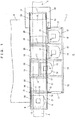
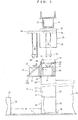
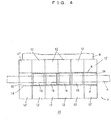
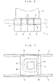
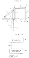
- FIGS. 1 to FIG. 10 show a temporary storage apparatus 2 for carriers (a temporary storage apparatus) according to an embodiment of the invention and modifications thereof.
- the temporary storage apparatus 2 is provided in a cleanroom or the like, and travelling rail 4 for an overhead travelling vehicles (OHT) 30, as is shown in FIG. 3 , is supported from the ceiling of the cleanroom.
- Reference numeral 6 indicates fabrication equipment for semiconductors or the like, and the equipment includes an inspection apparatus and is provided with one or more load ports 16.
- Articles such as semiconductor wafers and reticles are housed in a carrier 18 such as a FOUP (front-opening unified pod), the carrier is temporarily stored on slidable buffers 12 and fixed buffers 14 and is transported by the overhead travelling vehicle (OHT) 30 and a local vehicle 10.
- FOUP front-opening unified pod
- the temporary storage apparatus 2 is provided over a passage 7 in the cleanroom at a height without interference with people.
- a pair of travelling rails 8,8 are provided, a local vehicle 10 travels along the travelling rails 8,8 over the load ports 16 in parallel with the front surface of the equipment 6.
- the temporary storage apparatus 2 is provided with a frame 11, and, to the frame 11, a frame 13 of the slidable buffers 12 is attached by a hinge 15 so as to be rotatable by 90° about a horizontal axis parallel with the travelling rails 8,8.
- the slidable buffers 12 can move back and forth between an advanced position under the travelling rails 8,8 and a backward position laterally separated from positions under the travelling rails 8,8.
- a fixed buffer 14 is provided at one or both ends of the travelling rails 8,8. Positions over the load ports 16 and positions over the fixed buffers 14 are stopping positions for the local vehicle 10 and the overhead travelling vehicle 30, and the positions over the fixed buffers 14 also serve as waiting positions for the local vehicle 10.
- Further slidable buffers 12 may be provided in place of the fixed buffers 14 to omit the fixed buffers 14. Since positions not over the load ports 16 are used as the waiting positions for the local vehicle 10, a trouble of the local vehicle 10 does not prevent the transfer between the load ports 16 and the overhead travelling vehicle 30.
- the frame 13 is rotatably attached to the frame 11 by the hinge 15 and may be rotated downward by 90° from the attitude shown in FIG. 1 .
- a reference numeral 17 indicates a damper that applies an upward force to the frame 13.
- the damper 17 is an air cylinder, for example, and may be a hydraulic cylinder or a simple element such as a spring. Air necessary for driving the damper 17 is supplied via, for example, a trestle 24 shown in FIGS. 2 and 3 .
- Reference numerals 20 and 21 respectively indicate an optical sensor and a reflection plate which are provided at each stopping position.
- the optical sensor 20 detects an elevation platform extending from the overhead travelling vehicle 30, belts by which the elevation platform is suspended, or a carrier held by the elevation platform by detecting that the path between the optical sensor 20 and the reflection plate 21 has been blocked.
- Reference numeral 22 indicates a buffer controller that controls the local vehicle 10 and the slidable buffers 12, establishes interlock between the overhead travelling vehicle 30 and the local vehicle 10, communicates with a controller for the overhead travelling vehicle 30, and communicates with the equipment 6.
- the buffer controller 22 operates as follows:
- the temporary storage apparatus 2 is supported by a pair of trestles 24 that have a gate-like shape.
- Front faces 25 of the trestles 24 toward the passage 7 are located, relative to the passage 7, at approximately the same position as front faces 26 of the load ports 16 or closer to the equipment 6 than the front faces 26. Therefore, the width W of the passage 7 is dependent on the positions of the load ports 16, and temporary storage apparatus 2 does not make the width W of the passage 7 narrower.
- “Approximately the same” means that the difference between the front faces is up to ⁇ 100 mm, particularly up to ⁇ 50 mm, and preferably the front faces 25 and 26 are located at substantially the same position.
- the temporary storage apparatus 2 may be suspended from the ceiling of the cleanroom or from the travelling rail 4 for the overhead travelling vehicles 30. However, it is easy to transport, install, and position the temporary storage apparatus 2 supported by the trestles 24 into the cleanroom.
- the trestles 24 having the front faces 25 not protruding toward the passage 7 over the load ports 16 do not make the passage narrower.
- the trestle 24 comprises an upper part 27 and a lower part 28 fastened to each other by a screw or the like, and the lower part 28 is fixed on a floor surface or the like in the cleanroom by a connecting portion 29.
- the temporary storage apparatus 2 is fixed to the upper part 27 in advance, and the upper part 27 is fixed on the lower part 28 so as to install the temporary storage apparatus 2.
- the lower part 28 is made of a thick steel material or the like so as to be heavy.
- a travelling unit 32 travels in the travelling rail 4 and also supports a lateral transfer mechanism 33 which laterally moves a raising and lowering drive 34 in a horizontal direction orthogonal to the travelling rail 4.
- the raising and lowering drive 34 feeds and winds up suspenders such as belts 36 to raise and lower an elevation platform 35 that holds and releases a carrier 18.
- a hoist comprises the raising and lowering drive 34, the elevation platform 35, and the belts 36.
- the optical sensor 20 previously mentioned detects the hoist and the carrier supported by the hoist.
- Reference numeral 38 indicates an anti-fall hood that prevents the carrier 18 from falling.
- a mechanism for rotating the raising and lowering drive 34 about a vertical axis may also be provided.
- the slidable buffers 12 move forward to positions under the travelling rails 8,8.
- the temporary storage apparatus 2 shown in FIGS. 1 to 3 is provided with four slidable buffers 12 and two fixed buffers 14, and the equipment 6 is provided with four load ports 16, for example.
- a temporary storage apparatus 40 with maximum capacity for storing carriers 18 and serving the four load ports 16 is shown in FIGS. 4 and 5 .
- the fixed buffers 14 are located at positions lower than the slidable buffers 12 by a height corresponding to one carrier ( FIG. 5 ), and consequently the occupation height of the temporary storage apparatus 40 is made larger.
- the slidable buffers 12 are provided on both sides of the travelling rails 8,8, and further slidable buffers 12' are provided at positions above the fixed buffers 14 and shifted from the load ports 16 so that they move forward over the fixed buffer.
- eight slidable buffers 12, four slidable buffers 12' separated from the load ports 16, and two fixed buffers 14 are provided, and positions over the fixed buffers 14 are the waiting positions for the local vehicle 10.
- FIG. 6 shows a temporary storage apparatus 60 for small equipment 6' and with a smaller storage capacity.
- the equipment 6' is provided with two load ports 16, and the temporary storage apparatus 60 is provided with four slidable buffers. Positions over the slidable buffers 12' separated from the load ports 16 are the waiting positions for the local vehicle 10. While a structure similar to that shown in FIG. 5 allows two additional fixed buffers 14, it increases the height of the temporary storage apparatus 60.
- FIG. 7 shows the structure of the local vehicle 10.
- the local vehicle 10 travels along the pair of travelling rails 8 by wheels 62 and an unshown motor and raises and lowers an elevation platform 64 to hold and release the carrier 18 by a raising and lowering drive 63, unshown belts, and so on.
- the local vehicle 10 is further provided with a communication device to communicate with the buffer controller 22, another communication device to communicate with a terminal 30 for interlock between the overhead travelling vehicle, a power supply such as a battery, and an on-board controller.
- FIG. 8 shows the structure of the slidable buffer 12 which comprises a cell 72 and a guide mechanism 68 for moving the cell 72 between an advanced position and a backward position.
- Reference numeral 70 indicates a base of the guide mechanism 68 which is fixed to the frame 13.
- the cell 72 moves back and forth between the advanced position and the backward position along rails 71,71 by wheels 73.
- the advanced position is a position under the travelling rails for the local vehicle and, for example, over the load ports 16.
- the backward position is a position laterally separated from the advanced position.
- three positioning pins 74 provided on the cell 72 position the bottom portion of the carrier 18.
- a carrier sensor 75 detects whether the carrier 18 is present
- a seating sensor 76 detects whether the carrier 18 is seated at a correct position over the positioning pins 74
- a ID reader 77 reads the ID of the carrier.
- the ID reader 77 may be omitted, and both the sensors 75, 76 and the ID reader 77 are provided for the fixed buffers in the same manner.
- a linear guide 80 is moved back and forth along a rail 81 by a cylinder 78 such as a pneumatic cylinder or a hydraulic cylinder and a piston 79 or by a motor and a toothed belt or the like (not shown).
- the cell 72 is moved back and forth by a double speed mechanism comprising a toothed belt 82 and so on, at twice the stroke of the linear guide 80.
- the double speed mechanism has been widely used in slide forks, and another mechanism may be adopted to move the cell 72 back and forth.
- a sensor 83 detects that the linear guide 80 is at a backward position
- a sensor 84 detects that the linear guide 80 is at an advanced position.
- a cable guide 85 guides a power supply line and a signal line bendably and connects the sensors 75, 76 and the ID reader 77 to the base 70.
- the sensors 83 and 84 act to detect the positions of the cell 72, and the rails 71 may be provided with, for example, an optical sensor for detecting the front end position of the cell and an optical sensor for detecting the rear end position of the cell.
- the frame 13 and the slidable buffer 12 are configured to rotate about the hinge 15 by 90° between a horizontal attitude (the solid line) and a vertical attitude (the broken line).
- Reference numeral 86 in FIG. 8 indicates brackets provided at an tip end of the rail 71, and are provided with a pin hole 87 respectively.
- the brackets 86 are placed on brackets 88 of the frame 11 and the brackets 86 are fixed to the brackets 88 by pins 89 or the like.
- the pins 89 are removed and the frame 13 and the slidable buffer 12 are integrally rotated about the hinge 15.
- the slidable buffer 12 retracts from the gap between the travelling rails 8,8 to a retracted position, and therefore, the overhead travelling vehicle may transfer a carrier between a load port.
- the slidable buffers 12 retract in the counterclockwise direction, however, it may rotate and retract in the clockwise direction. Also, while the frame 13 and all of the slidable buffers 12 are rotated together in the embodiment, the slidable buffers 12 may be configured to rotate individually.
- the total weight of the frame 13 and the slidable buffers 12 are too heavy to be manually rotated. Therefore, an upward force is applied to the frame 13 by the damper 17 so as to rotate manually the frame 13 and the slidable buffers 12 easily.
- FIG. 10 shows a relationship between the buffer controller 22 and an overhead travelling vehicle controller 100.
- An overhead travelling vehicle controller 100 stores a map 102 of the travelling path in a memory, and the map 102 indicates the positions of the slidable buffers 12 as well as the alternative destinations.
- the buffer controller 22 notifies the overhead travelling vehicle controller 100 that the slidable buffers are disabled, and the overhead travelling vehicle controller 100 writes this in the map 102.
- the overhead travelling vehicle controller 100 changes an instruction of which designation is the temporary storage apparatus 2 to an instruction to an alternative destination. If no alternative destination is registered, based on the map 102, a new alternative destination is decided. With this arrangement, if a slidable buffer is temporarily disabled according to maintenance work of the equipment and so on, transportation by the overhead travelling vehicles are not disturbed.
- the embodiment has the following advantageous effects.
- the guide mechanism 68 and the cell 72 are retracted by the hinge 15 with rotation about the horizontal axis, however, the retraction mechanism is arbitrary.
- the temporary storage apparatus 2 may be supported from the ceiling via the travelling rail 4 for the overhead travelling vehicle, or the like, without the trestle 24.
Landscapes
- Container, Conveyance, Adherence, Positioning, Of Wafer (AREA)
- Warehouses Or Storage Devices (AREA)
- Control Of Position, Course, Altitude, Or Attitude Of Moving Bodies (AREA)
Claims (5)
- Eine Vorrichtung zur vorübergehenden Lagerung zum vorübergehenden Lagern von Trägern (18) zwischen sich hängend bewegenden Fahrzeugen (30) und einer Ladeöffnung (16), die sich vor einer Ausrüstung (6) befindet, wobei die Vorrichtung zur vorübergehenden Lagerung folgende Merkmale aufweist:ein lokales Fahrzeug (10), das mit einem Aufzug versehen ist, der zum Anheben und Absenken eines Trägers (18) ausgebildet ist;eine Fahrschiene (8) für das lokale Fahrzeug (10), die über der Ladeöffnung (16) verläuft und unter einem Fahrweg (4) der sich hängend bewegenden Fahrzeuge (30) vorgesehen ist; undeinen gleitfähigen Puffer (12), der folgende Merkmale aufweist:eine Zelle (72), die dazu ausgebildet ist, einen Träger (18) auf derselben zu tragen; undeinen Führungsmechanismus (68), der dazu ausgebildet ist, die Zelle (72) zu tragen und zwischen einer vorgerückten Position, die sich unter der Fahrschiene (8) befindet, und einer weiter hinten befindlichen Position, die seitlich von der Fahrschiene (8) getrennt ist, gleitend zu bewegen,wobei der Führungsmechanismus (68) dazu ausgebildet ist, sich zwischen einer aktiven Position, die seitlich von der Fahrschiene (8) vorsteht, und einer eingefahrenen Position zu bewegen, die um eine kürzere Strecke als die aktive Position seitlich weniger weit von der Fahrschiene (8) vorsteht und ermöglicht, dass ein sich hängend bewegendes Fahrzeug (30) einen Träger (18) zu der Ladeöffnung (16) transferiert,wobei sich die Fahrschiene (8) entlang einer Vorderfläche der Ausrüstung (6) bis zu einer Warteposition auf das lokale Fahrzeug (10) erstreckt, undwobei das lokale Fahrzeug (10) dazu ausgebildet ist, in der Warteposition zu warten, wenn dem lokalen Fahrzeug (10) keine Arbeit zugewiesen ist,wobei die Vorrichtung zur vorübergehenden Lagerung ferner folgende Merkmale aufweist:einen Rahmen (13);wobei der Führungsmechanismus (68) auf drehbare Weise um eine zu der Fahrschiene (8) parallele Achse herum zusammen mit der Zelle (72) an dem Rahmen (13) befestigt ist, undwobei der Führungsmechanismus (68) und die Zelle (72) von der vorgerückten Position und der weiter hinten befindlichen Position unter der Fahrschiene (8) in der eingefahrenen Position getrennt sind.
- Die Vorrichtung zur vorübergehenden Lagerung gemäß Anspruch 1, die ferner folgendes Merkmal aufweist:eine Steuerung (22), die dazu ausgebildet ist, den gleitfähigen Puffer (12) und das lokale Fahrzeug (10) zu steuern,wobei die Steuerung (22) dazu ausgebildet und programmiert ist, eine OHT-Steuerung (100) für das sich hängend bewegende Fahrzeug (30) davon zu benachrichtigen, dass der gleitfähige Puffer (12) deaktiviert ist, wenn sich der Führungsmechanismus (68) in der eingefahrenen Position befindet.
- Die Vorrichtung zur vorübergehenden Lagerung gemäß Anspruch 1, die ferner eine horizontale Achse aufweist, die den Führungsmechanismus (68) drehbar trägt, so dass sich der Führungsmechanismus (68) entlang einer vertikalen Richtung in der eingefahrenen Position erstreckt.
- Die Vorrichtung zur vorübergehenden Lagerung gemäß einem der Ansprüche 1 bis 3, die ferner folgende Merkmale aufweist:ein unteres Gestellteil, das dazu ausgebildet ist, auf einer Bodenoberfläche befestigt zu werden, undein oberes Gestellteil, das von dem unteren Gestellteil abnehmbar ist und einen Rahmen (13) der Vorrichtung zur vorübergehenden Lagerung aufweist,wobei die Fahrschiene (8) und der Führungsmechanismus (68) an dem Rahmen (13) befestigt sind.
- Ein Verfahren zur vorübergehenden Lagerung zum vorübergehenden Lagern von Trägern (18) zwischen sich hängend bewegenden Fahrzeugen (30) und einer Ladeöffnung (16), die sich vor einer Ausrüstung (6) befindet, unter Verwendung einer Vorrichtung zur vorübergehenden Lagerung, die folgende Merkmale aufweist:ein lokales Fahrzeug (10), das mit einem Aufzug versehen ist, der zum Anheben und Absenken eines Trägers (18) ausgebildet ist;eine Fahrschiene (8) für das lokale Fahrzeug (10), die über der Ladeöffnung (16) verläuft und unter einem Fahrweg (4) der sich hängend bewegenden Fahrzeuge (30) vorgesehen ist; undeinen gleitfähigen Puffer (12), der folgende Merkmale aufweist:eine Zelle (72), die dazu ausgebildet ist, einen Träger (18) auf derselben zu tragen; undeinen Führungsmechanismus (68), der dazu ausgebildet ist, die Zelle (72) zu tragen und zwischen einer vorgerückten Position, die sich unter der Fahrschiene (8) befindet, und einer weiter hinten befindlichen Position, die seitlich von der Fahrschiene (8) getrennt ist, gleitend zu bewegen, undeine horizontale Achse, die dazu ausgebildet ist, den Führungsmechanismus (68) zu drehen,wobei das Verfahren zur vorübergehenden Lagerung folgende Schritte aufweist:unter der Steuerung einer Steuerung (22), Bewegen des lokalen Fahrzeugs (10) zu einer Warteposition, um zu warten, wenn dem lokalen Fahrzeug (10) keine Arbeit zugewiesen ist; undVerändern einer Stellung des gleitfähigen Puffers (12) zwischen einer aktiven Position, in der der Führungsmechanismus (68) lateral von der Fahrschiene (8) vorsteht, und einer eingefahrenen Position, in der sich der Führungsmechanismus (68) in einer Höhenrichtung erstreckt, indem der gleitfähige Puffer (12) um die horizontale Achse gedreht wird.
Applications Claiming Priority (2)
| Application Number | Priority Date | Filing Date | Title |
|---|---|---|---|
| JP2014126014 | 2014-06-19 | ||
| PCT/JP2015/062939 WO2015194265A1 (ja) | 2014-06-19 | 2015-04-30 | キャリアの一時保管装置と一時保管方法 |
Publications (3)
| Publication Number | Publication Date |
|---|---|
| EP3159920A1 EP3159920A1 (de) | 2017-04-26 |
| EP3159920A4 EP3159920A4 (de) | 2018-02-14 |
| EP3159920B1 true EP3159920B1 (de) | 2021-06-16 |
Family
ID=54935260
Family Applications (1)
| Application Number | Title | Priority Date | Filing Date |
|---|---|---|---|
| EP15809185.0A Active EP3159920B1 (de) | 2014-06-19 | 2015-04-30 | Trägerpufferungsvorrichtung und pufferungsverfahren |
Country Status (6)
| Country | Link |
|---|---|
| US (1) | US10256129B2 (de) |
| EP (1) | EP3159920B1 (de) |
| JP (1) | JP6260697B2 (de) |
| CN (1) | CN106463441B (de) |
| TW (1) | TWI636937B (de) |
| WO (1) | WO2015194265A1 (de) |
Families Citing this family (8)
| Publication number | Priority date | Publication date | Assignee | Title |
|---|---|---|---|---|
| EP3159923B1 (de) * | 2014-06-19 | 2021-06-16 | Murata Machinery, Ltd. | Trägerpufferungsvorrichtung und pufferungsverfahren |
| SG11201801076VA (en) * | 2015-08-14 | 2018-03-28 | Murata Machinery Ltd | Conveyance system |
| SG11201804593PA (en) * | 2015-12-08 | 2018-06-28 | Murata Machinery Ltd | Conveyance system and conveyance method |
| CN110235235B (zh) * | 2017-04-06 | 2023-01-06 | 村田机械株式会社 | 桥式输送车系统以及示教单元 |
| CN108962804B (zh) * | 2017-05-19 | 2021-08-10 | 沈阳芯源微电子设备股份有限公司 | 一种不间断式进片回片装置及控制方法 |
| CN108449898B (zh) * | 2018-03-23 | 2021-01-05 | 苏州佳世达电通有限公司 | 电子装置及支架 |
| WO2020195240A1 (ja) * | 2019-03-22 | 2020-10-01 | 村田機械株式会社 | 搬送車システム |
| US20230411193A1 (en) * | 2022-06-17 | 2023-12-21 | Taiwan Semiconductor Manufacturing Co., Ltd. | Automated material handling system for use in power outage recovery |
Family Cites Families (9)
| Publication number | Priority date | Publication date | Assignee | Title |
|---|---|---|---|---|
| JP4796024B2 (ja) * | 2007-08-30 | 2011-10-19 | 東京エレクトロン株式会社 | 容器交換システム及び容器交換方法 |
| CN101630634A (zh) * | 2008-06-30 | 2010-01-20 | 因特维克有限公司 | 用于基板传输的系统和方法 |
| KR101015225B1 (ko) * | 2008-07-07 | 2011-02-18 | 세메스 주식회사 | 기판 처리장치 및 이의 기판 이송 방법 |
| US8527088B2 (en) | 2009-03-03 | 2013-09-03 | Murata Machinery, Ltd. | Transportation system |
| US8882433B2 (en) * | 2009-05-18 | 2014-11-11 | Brooks Automation, Inc. | Integrated systems for interfacing with substrate container storage systems |
| KR101126160B1 (ko) | 2009-09-11 | 2012-03-22 | 세메스 주식회사 | 기판 처리 장치 |
| JP5445015B2 (ja) * | 2009-10-14 | 2014-03-19 | シンフォニアテクノロジー株式会社 | キャリア移載促進装置 |
| JP5429570B2 (ja) * | 2010-03-08 | 2014-02-26 | 株式会社ダイフク | 物品搬送設備 |
| JP5229363B2 (ja) * | 2010-11-04 | 2013-07-03 | 村田機械株式会社 | 搬送システム及び搬送方法 |
-
2015
- 2015-04-30 CN CN201580028530.XA patent/CN106463441B/zh active Active
- 2015-04-30 EP EP15809185.0A patent/EP3159920B1/de active Active
- 2015-04-30 US US15/315,345 patent/US10256129B2/en active Active
- 2015-04-30 WO PCT/JP2015/062939 patent/WO2015194265A1/ja not_active Ceased
- 2015-04-30 JP JP2016529151A patent/JP6260697B2/ja active Active
- 2015-06-16 TW TW104119411A patent/TWI636937B/zh not_active IP Right Cessation
Non-Patent Citations (1)
| Title |
|---|
| None * |
Also Published As
| Publication number | Publication date |
|---|---|
| JP6260697B2 (ja) | 2018-01-17 |
| TW201600429A (zh) | 2016-01-01 |
| JPWO2015194265A1 (ja) | 2017-04-20 |
| EP3159920A1 (de) | 2017-04-26 |
| TWI636937B (zh) | 2018-10-01 |
| WO2015194265A1 (ja) | 2015-12-23 |
| US10256129B2 (en) | 2019-04-09 |
| CN106463441A (zh) | 2017-02-22 |
| EP3159920A4 (de) | 2018-02-14 |
| CN106463441B (zh) | 2019-04-23 |
| US20170186639A1 (en) | 2017-06-29 |
Similar Documents
| Publication | Publication Date | Title |
|---|---|---|
| EP3159920B1 (de) | Trägerpufferungsvorrichtung und pufferungsverfahren | |
| TWI828841B (zh) | 保管系統 | |
| EP3159922B1 (de) | Trägertransportsystem und -transportverfahren | |
| EP3159923B1 (de) | Trägerpufferungsvorrichtung und pufferungsverfahren | |
| EP2450296B1 (de) | System und Verfahren zum Transportieren eines Artikels zwischen Verarbeitungseinrichtungen | |
| JP5429570B2 (ja) | 物品搬送設備 | |
| CN110831873B (zh) | 搬运系统以及搬运方法 | |
| US9548230B2 (en) | Temporary storage device, transport system, and temporary storage method | |
| TWI828842B (zh) | 保管系統 | |
| JPWO2015194267A6 (ja) | キャリアの搬送システムと搬送方法 | |
| TW202026216A (zh) | 保管系統 | |
| EP3159921B1 (de) | Trägerpufferungsvorrichtung und speicherverfahren | |
| WO2019021708A1 (ja) | 自動倉庫システム、及び自動倉庫システムの制御方法 | |
| JP2016004958A (ja) | キャリアの一時保管装置 |
Legal Events
| Date | Code | Title | Description |
|---|---|---|---|
| STAA | Information on the status of an ep patent application or granted ep patent |
Free format text: STATUS: THE INTERNATIONAL PUBLICATION HAS BEEN MADE |
|
| PUAI | Public reference made under article 153(3) epc to a published international application that has entered the european phase |
Free format text: ORIGINAL CODE: 0009012 |
|
| STAA | Information on the status of an ep patent application or granted ep patent |
Free format text: STATUS: REQUEST FOR EXAMINATION WAS MADE |
|
| 17P | Request for examination filed |
Effective date: 20161129 |
|
| AK | Designated contracting states |
Kind code of ref document: A1 Designated state(s): AL AT BE BG CH CY CZ DE DK EE ES FI FR GB GR HR HU IE IS IT LI LT LU LV MC MK MT NL NO PL PT RO RS SE SI SK SM TR |
|
| AX | Request for extension of the european patent |
Extension state: BA ME |
|
| DAV | Request for validation of the european patent (deleted) | ||
| DAX | Request for extension of the european patent (deleted) | ||
| A4 | Supplementary search report drawn up and despatched |
Effective date: 20180117 |
|
| RIC1 | Information provided on ipc code assigned before grant |
Ipc: H01L 21/677 20060101AFI20180111BHEP |
|
| GRAP | Despatch of communication of intention to grant a patent |
Free format text: ORIGINAL CODE: EPIDOSNIGR1 |
|
| STAA | Information on the status of an ep patent application or granted ep patent |
Free format text: STATUS: GRANT OF PATENT IS INTENDED |
|
| INTG | Intention to grant announced |
Effective date: 20201221 |
|
| GRAS | Grant fee paid |
Free format text: ORIGINAL CODE: EPIDOSNIGR3 |
|
| GRAA | (expected) grant |
Free format text: ORIGINAL CODE: 0009210 |
|
| STAA | Information on the status of an ep patent application or granted ep patent |
Free format text: STATUS: THE PATENT HAS BEEN GRANTED |
|
| AK | Designated contracting states |
Kind code of ref document: B1 Designated state(s): AL AT BE BG CH CY CZ DE DK EE ES FI FR GB GR HR HU IE IS IT LI LT LU LV MC MK MT NL NO PL PT RO RS SE SI SK SM TR |
|
| REG | Reference to a national code |
Ref country code: GB Ref legal event code: FG4D |
|
| REG | Reference to a national code |
Ref country code: CH Ref legal event code: EP |
|
| REG | Reference to a national code |
Ref country code: DE Ref legal event code: R096 Ref document number: 602015070482 Country of ref document: DE |
|
| REG | Reference to a national code |
Ref country code: AT Ref legal event code: REF Ref document number: 1403035 Country of ref document: AT Kind code of ref document: T Effective date: 20210715 |
|
| REG | Reference to a national code |
Ref country code: IE Ref legal event code: FG4D |
|
| REG | Reference to a national code |
Ref country code: LT Ref legal event code: MG9D |
|
| PG25 | Lapsed in a contracting state [announced via postgrant information from national office to epo] |
Ref country code: HR Free format text: LAPSE BECAUSE OF FAILURE TO SUBMIT A TRANSLATION OF THE DESCRIPTION OR TO PAY THE FEE WITHIN THE PRESCRIBED TIME-LIMIT Effective date: 20210616 Ref country code: BG Free format text: LAPSE BECAUSE OF FAILURE TO SUBMIT A TRANSLATION OF THE DESCRIPTION OR TO PAY THE FEE WITHIN THE PRESCRIBED TIME-LIMIT Effective date: 20210916 Ref country code: LT Free format text: LAPSE BECAUSE OF FAILURE TO SUBMIT A TRANSLATION OF THE DESCRIPTION OR TO PAY THE FEE WITHIN THE PRESCRIBED TIME-LIMIT Effective date: 20210616 Ref country code: FI Free format text: LAPSE BECAUSE OF FAILURE TO SUBMIT A TRANSLATION OF THE DESCRIPTION OR TO PAY THE FEE WITHIN THE PRESCRIBED TIME-LIMIT Effective date: 20210616 |
|
| REG | Reference to a national code |
Ref country code: AT Ref legal event code: MK05 Ref document number: 1403035 Country of ref document: AT Kind code of ref document: T Effective date: 20210616 |
|
| REG | Reference to a national code |
Ref country code: NL Ref legal event code: MP Effective date: 20210616 |
|
| PG25 | Lapsed in a contracting state [announced via postgrant information from national office to epo] |
Ref country code: GR Free format text: LAPSE BECAUSE OF FAILURE TO SUBMIT A TRANSLATION OF THE DESCRIPTION OR TO PAY THE FEE WITHIN THE PRESCRIBED TIME-LIMIT Effective date: 20210917 Ref country code: LV Free format text: LAPSE BECAUSE OF FAILURE TO SUBMIT A TRANSLATION OF THE DESCRIPTION OR TO PAY THE FEE WITHIN THE PRESCRIBED TIME-LIMIT Effective date: 20210616 Ref country code: SE Free format text: LAPSE BECAUSE OF FAILURE TO SUBMIT A TRANSLATION OF THE DESCRIPTION OR TO PAY THE FEE WITHIN THE PRESCRIBED TIME-LIMIT Effective date: 20210616 Ref country code: RS Free format text: LAPSE BECAUSE OF FAILURE TO SUBMIT A TRANSLATION OF THE DESCRIPTION OR TO PAY THE FEE WITHIN THE PRESCRIBED TIME-LIMIT Effective date: 20210616 Ref country code: NO Free format text: LAPSE BECAUSE OF FAILURE TO SUBMIT A TRANSLATION OF THE DESCRIPTION OR TO PAY THE FEE WITHIN THE PRESCRIBED TIME-LIMIT Effective date: 20210916 |
|
| PG25 | Lapsed in a contracting state [announced via postgrant information from national office to epo] |
Ref country code: PT Free format text: LAPSE BECAUSE OF FAILURE TO SUBMIT A TRANSLATION OF THE DESCRIPTION OR TO PAY THE FEE WITHIN THE PRESCRIBED TIME-LIMIT Effective date: 20211018 Ref country code: NL Free format text: LAPSE BECAUSE OF FAILURE TO SUBMIT A TRANSLATION OF THE DESCRIPTION OR TO PAY THE FEE WITHIN THE PRESCRIBED TIME-LIMIT Effective date: 20210616 Ref country code: RO Free format text: LAPSE BECAUSE OF FAILURE TO SUBMIT A TRANSLATION OF THE DESCRIPTION OR TO PAY THE FEE WITHIN THE PRESCRIBED TIME-LIMIT Effective date: 20210616 Ref country code: ES Free format text: LAPSE BECAUSE OF FAILURE TO SUBMIT A TRANSLATION OF THE DESCRIPTION OR TO PAY THE FEE WITHIN THE PRESCRIBED TIME-LIMIT Effective date: 20210616 Ref country code: AT Free format text: LAPSE BECAUSE OF FAILURE TO SUBMIT A TRANSLATION OF THE DESCRIPTION OR TO PAY THE FEE WITHIN THE PRESCRIBED TIME-LIMIT Effective date: 20210616 Ref country code: EE Free format text: LAPSE BECAUSE OF FAILURE TO SUBMIT A TRANSLATION OF THE DESCRIPTION OR TO PAY THE FEE WITHIN THE PRESCRIBED TIME-LIMIT Effective date: 20210616 Ref country code: CZ Free format text: LAPSE BECAUSE OF FAILURE TO SUBMIT A TRANSLATION OF THE DESCRIPTION OR TO PAY THE FEE WITHIN THE PRESCRIBED TIME-LIMIT Effective date: 20210616 Ref country code: SM Free format text: LAPSE BECAUSE OF FAILURE TO SUBMIT A TRANSLATION OF THE DESCRIPTION OR TO PAY THE FEE WITHIN THE PRESCRIBED TIME-LIMIT Effective date: 20210616 Ref country code: SK Free format text: LAPSE BECAUSE OF FAILURE TO SUBMIT A TRANSLATION OF THE DESCRIPTION OR TO PAY THE FEE WITHIN THE PRESCRIBED TIME-LIMIT Effective date: 20210616 |
|
| PG25 | Lapsed in a contracting state [announced via postgrant information from national office to epo] |
Ref country code: PL Free format text: LAPSE BECAUSE OF FAILURE TO SUBMIT A TRANSLATION OF THE DESCRIPTION OR TO PAY THE FEE WITHIN THE PRESCRIBED TIME-LIMIT Effective date: 20210616 |
|
| REG | Reference to a national code |
Ref country code: DE Ref legal event code: R097 Ref document number: 602015070482 Country of ref document: DE |
|
| PLBE | No opposition filed within time limit |
Free format text: ORIGINAL CODE: 0009261 |
|
| STAA | Information on the status of an ep patent application or granted ep patent |
Free format text: STATUS: NO OPPOSITION FILED WITHIN TIME LIMIT |
|
| PG25 | Lapsed in a contracting state [announced via postgrant information from national office to epo] |
Ref country code: DK Free format text: LAPSE BECAUSE OF FAILURE TO SUBMIT A TRANSLATION OF THE DESCRIPTION OR TO PAY THE FEE WITHIN THE PRESCRIBED TIME-LIMIT Effective date: 20210616 |
|
| 26N | No opposition filed |
Effective date: 20220317 |
|
| PG25 | Lapsed in a contracting state [announced via postgrant information from national office to epo] |
Ref country code: AL Free format text: LAPSE BECAUSE OF FAILURE TO SUBMIT A TRANSLATION OF THE DESCRIPTION OR TO PAY THE FEE WITHIN THE PRESCRIBED TIME-LIMIT Effective date: 20210616 |
|
| PG25 | Lapsed in a contracting state [announced via postgrant information from national office to epo] |
Ref country code: IT Free format text: LAPSE BECAUSE OF FAILURE TO SUBMIT A TRANSLATION OF THE DESCRIPTION OR TO PAY THE FEE WITHIN THE PRESCRIBED TIME-LIMIT Effective date: 20210616 |
|
| REG | Reference to a national code |
Ref country code: CH Ref legal event code: PL |
|
| GBPC | Gb: european patent ceased through non-payment of renewal fee |
Effective date: 20220430 |
|
| REG | Reference to a national code |
Ref country code: BE Ref legal event code: MM Effective date: 20220430 |
|
| PG25 | Lapsed in a contracting state [announced via postgrant information from national office to epo] |
Ref country code: MC Free format text: LAPSE BECAUSE OF FAILURE TO SUBMIT A TRANSLATION OF THE DESCRIPTION OR TO PAY THE FEE WITHIN THE PRESCRIBED TIME-LIMIT Effective date: 20210616 Ref country code: LU Free format text: LAPSE BECAUSE OF NON-PAYMENT OF DUE FEES Effective date: 20220430 Ref country code: LI Free format text: LAPSE BECAUSE OF NON-PAYMENT OF DUE FEES Effective date: 20220430 Ref country code: GB Free format text: LAPSE BECAUSE OF NON-PAYMENT OF DUE FEES Effective date: 20220430 Ref country code: FR Free format text: LAPSE BECAUSE OF NON-PAYMENT OF DUE FEES Effective date: 20220430 Ref country code: CH Free format text: LAPSE BECAUSE OF NON-PAYMENT OF DUE FEES Effective date: 20220430 |
|
| PG25 | Lapsed in a contracting state [announced via postgrant information from national office to epo] |
Ref country code: BE Free format text: LAPSE BECAUSE OF NON-PAYMENT OF DUE FEES Effective date: 20220430 |
|
| PG25 | Lapsed in a contracting state [announced via postgrant information from national office to epo] |
Ref country code: HU Free format text: LAPSE BECAUSE OF FAILURE TO SUBMIT A TRANSLATION OF THE DESCRIPTION OR TO PAY THE FEE WITHIN THE PRESCRIBED TIME-LIMIT; INVALID AB INITIO Effective date: 20150430 |
|
| PG25 | Lapsed in a contracting state [announced via postgrant information from national office to epo] |
Ref country code: MK Free format text: LAPSE BECAUSE OF FAILURE TO SUBMIT A TRANSLATION OF THE DESCRIPTION OR TO PAY THE FEE WITHIN THE PRESCRIBED TIME-LIMIT Effective date: 20210616 Ref country code: CY Free format text: LAPSE BECAUSE OF FAILURE TO SUBMIT A TRANSLATION OF THE DESCRIPTION OR TO PAY THE FEE WITHIN THE PRESCRIBED TIME-LIMIT Effective date: 20210616 |
|
| PG25 | Lapsed in a contracting state [announced via postgrant information from national office to epo] |
Ref country code: TR Free format text: LAPSE BECAUSE OF FAILURE TO SUBMIT A TRANSLATION OF THE DESCRIPTION OR TO PAY THE FEE WITHIN THE PRESCRIBED TIME-LIMIT Effective date: 20210616 |
|
| PG25 | Lapsed in a contracting state [announced via postgrant information from national office to epo] |
Ref country code: MT Free format text: LAPSE BECAUSE OF FAILURE TO SUBMIT A TRANSLATION OF THE DESCRIPTION OR TO PAY THE FEE WITHIN THE PRESCRIBED TIME-LIMIT Effective date: 20210616 |
|
| PGFP | Annual fee paid to national office [announced via postgrant information from national office to epo] |
Ref country code: IE Payment date: 20250321 Year of fee payment: 11 |
|
| PGFP | Annual fee paid to national office [announced via postgrant information from national office to epo] |
Ref country code: DE Payment date: 20250319 Year of fee payment: 11 |
|
| REG | Reference to a national code |
Ref country code: DE Ref legal event code: R079 Ref document number: 602015070482 Country of ref document: DE Free format text: PREVIOUS MAIN CLASS: H01L0021677000 Ipc: H10P0072300000 |