EP3159923B1 - Dispositif de mise en réserve de chariot et procédé de mise en réserve - Google Patents
Dispositif de mise en réserve de chariot et procédé de mise en réserve Download PDFInfo
- Publication number
- EP3159923B1 EP3159923B1 EP15810356.4A EP15810356A EP3159923B1 EP 3159923 B1 EP3159923 B1 EP 3159923B1 EP 15810356 A EP15810356 A EP 15810356A EP 3159923 B1 EP3159923 B1 EP 3159923B1
- Authority
- EP
- European Patent Office
- Prior art keywords
- travelling
- local vehicle
- vehicle
- carrier
- buffer
- Prior art date
- Legal status (The legal status is an assumption and is not a legal conclusion. Google has not performed a legal analysis and makes no representation as to the accuracy of the status listed.)
- Active
Links
Images






Classifications
-
- H—ELECTRICITY
- H10—SEMICONDUCTOR DEVICES; ELECTRIC SOLID-STATE DEVICES NOT OTHERWISE PROVIDED FOR
- H10P—GENERIC PROCESSES OR APPARATUS FOR THE MANUFACTURE OR TREATMENT OF DEVICES COVERED BY CLASS H10
- H10P72/00—Handling or holding of wafers, substrates or devices during manufacture or treatment thereof
- H10P72/30—Handling or holding of wafers, substrates or devices during manufacture or treatment thereof for conveying, e.g. between different workstations
- H10P72/32—Handling or holding of wafers, substrates or devices during manufacture or treatment thereof for conveying, e.g. between different workstations between different workstations
- H10P72/3221—Overhead conveying
-
- H—ELECTRICITY
- H10—SEMICONDUCTOR DEVICES; ELECTRIC SOLID-STATE DEVICES NOT OTHERWISE PROVIDED FOR
- H10P—GENERIC PROCESSES OR APPARATUS FOR THE MANUFACTURE OR TREATMENT OF DEVICES COVERED BY CLASS H10
- H10P72/00—Handling or holding of wafers, substrates or devices during manufacture or treatment thereof
- H10P72/30—Handling or holding of wafers, substrates or devices during manufacture or treatment thereof for conveying, e.g. between different workstations
- H10P72/32—Handling or holding of wafers, substrates or devices during manufacture or treatment thereof for conveying, e.g. between different workstations between different workstations
- H10P72/3222—Loading to or unloading from a conveyor
-
- H—ELECTRICITY
- H10—SEMICONDUCTOR DEVICES; ELECTRIC SOLID-STATE DEVICES NOT OTHERWISE PROVIDED FOR
- H10P—GENERIC PROCESSES OR APPARATUS FOR THE MANUFACTURE OR TREATMENT OF DEVICES COVERED BY CLASS H10
- H10P72/00—Handling or holding of wafers, substrates or devices during manufacture or treatment thereof
- H10P72/30—Handling or holding of wafers, substrates or devices during manufacture or treatment thereof for conveying, e.g. between different workstations
- H10P72/34—Handling or holding of wafers, substrates or devices during manufacture or treatment thereof for conveying, e.g. between different workstations the wafers being stored in a carrier, involving loading and unloading
- H10P72/3404—Storage means
Definitions
- the present invention relates to temporarily storing a carrier in which semiconductor wafers or the like are housed.
- Patent Literature 1 JP 2012-111635 ) by the applicant has proposed to provide a travelling rail for a local vehicle in parallel with and below a travelling rail for overhead travelling vehicles (overhead hoist transports (OHT)). If buffers suitable for transfer between the local vehicle and between the overhead travelling vehicles are provided at positions under the travelling rail for the local vehicle and not over the load ports, for example, four buffers may be provided. If the buffers are not sufficient in its number, then, providing the overhead travelling vehicles and the local vehicle with a lateral transfer mechanism for carriers and providing additional buffers at downward and sideway positions from the travelling rail for the local vehicle are a possible design for increasing the number of buffers.
- OHT overhead hoist transports
- Patent Literature 1 JP 2012-111635
- US2010/0290873 discloses integrated systems for interfacing with substrate container storage systems.
- the problem to be solved by the present invention is to increase the buffering capacity of a temporary storage apparatus without providing the local vehicle with a lateral transfer mechanism.
- a temporary storage apparatus according to the present invention is defined in claim 1.
- a method for temporarily storing carriers according to the present invention is defined in claim 7.
- At least one of the slidable buffers is allocated such that said position under the travelling rail is located over the load port.
- a slidable buffer configured to advance a position over the load port is provided.
- a plurality of slidable buffers are preferably provided in a row along one side of the travelling rail for the local vehicle or preferably provided in two rows along both sides of the travelling rail for the local vehicle so that each row has plural slidable buffers.
- descriptions regarding the temporary storage apparatus for storing carriers also apply to the method for temporarily storing carriers as they are.
- the controller may instruct the local vehicle to wait, or the local vehicle may autonomously move to the waiting position.
- the waiting position may be provided at one end of the travelling rail for the local vehicle, or at both ends thereof.
- a fixed buffer configured to support a carrier thereon is provided at a position under the travelling rail for the local vehicle, not over the load port, and including an area under the waiting position. This increases the buffering capacity further.
- the fixed buffer is located at a lower position than the slidable buffer by a height corresponding to one carrier, further slidable buffer advancing toward a position over the fixed buffer may be provided.
- a space over the slidable buffer is open.
- an overhead travelling vehicle which is provided with both a hoist for raising and lowering a carrier and a lateral transfer mechanism for laterally transferring the hoist is capable of transferring a carrier between the slidable buffer by the lateral transfer mechanism and the hoist through the space. Therefore, an overhead travelling vehicles provided with the lateral transfer mechanism may transfer a carrier between the slidable buffer at the position laterally separated from positions under the travelling rail for the local vehicle.
- both a slidable buffer configured to slide toward one lateral side of the travelling rail for the local vehicle and a slidable buffer configured to slide toward the other lateral side of the travelling rail are provided, and the number of the slidable buffers is increased.
- the slidable buffer comprises a base and a movable pedestal configured to move forward from the base to a position under the travelling rail for the local vehicle, said base is fixed at a position laterally separated from the position under the travelling rail for the local vehicle.
- a sensor configured to detect that the pedestal is located at the position under the travelling rail for the local vehicle, and a sensor configured to detect that the pedestal is located at a position over the base are provided, and said controller is configured and programmed to permit the overhead travelling vehicles and the local vehicle to transfer a carrier between the slidable buffer according to a detected position of the pedestal.
- the pedestal is provided with a sensor configured to detect whether a carrier is present, and the controller is configured and programmed to permit the overhead travelling vehicles and the local vehicle to transfer a carrier between the slidable buffer depending on whether a carrier is present.
- the controller is configured and programmed to permit the overhead travelling vehicles and the local vehicle to transfer a carrier between the slidable buffer depending on whether a carrier is present.
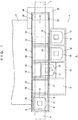
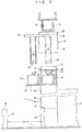
- FIGS. 1 to FIG. 12 show a temporary storage apparatus 2 for carriers (a temporary storage apparatus) according to an embodiment of the invention and modifications thereof.
- the temporary storage apparatus 2 is provided in a cleanroom or the like, and travelling rail 4 for an overhead travelling vehicles (OHT) 30, as is shown in FIG. 3 , is supported from the ceiling of the cleanroom.
- Reference numeral 6 indicates fabrication equipment for semiconductors or the like.
- the equipment includes an inspection apparatus and is provided with one or more load ports 16.
- Articles such as semiconductor wafers and reticles are housed in a carrier 18 such as a front-opening unified pod (FOUP), the carrier is temporarily stored on slidable buffers 12 and fixed buffers 14 and is transported by the overhead travelling vehicle (OHT) 30 and a local vehicle 10.
- FOUP front-opening unified pod
- the temporary storage apparatus 2 is provided over a passage 7 in the cleanroom at a height without interference with people.
- the local vehicle 10 travels along a pair of travelling rails 8,8 over the row of load ports 16 in parallel with the equipment 6.
- the slidable buffers 12 are supported by a frame 13 of the temporary storage apparatus 2, at positions corresponding to the load ports 16 and so on, for example, at positions shifted sideways from an area over the load ports 16.
- a plurality of slidable buffers 12 are supported in a row or in rows; however, only one slidable buffer 12 may be provided.
- the slidable buffers 12 are configured to move back and forth between a forward position under the travelling rails 8,8, and, for example, over the load ports 16 and a rearward position laterally separated from the position under the travelling rails 8,8.
- at least a fixed buffer 14 is provided at one end or both ends of the travelling rails 8,8.
- Positions over the load ports 16 and positions over the fixed buffers 14 are stop positions for the local vehicle 10 and the overhead travelling vehicles 30, and the positions over the fixed buffers 14 also serve as waiting positions for the local vehicle 10.
- slidable buffers 12 may be provided in place of the fixed buffers 14 to omit the fixed buffers 14.
- Positions not over the load ports 16 are allocated as waiting positions for the local vehicle 10. Therefore, a trouble of the local vehicle 10 will not prevent the transfer between the load ports 16 and the overhead travelling vehicles 30.
- the stop positions for the local vehicle 10 and the overhead travelling vehicles 30 correspond one-to-one to the load ports 16 or the fixed buffers 14. Note that the stop positions corresponding to the load ports 16 also serve as stop positions corresponding to the slidable buffers 12.
- Terminals 100 to 102 shown in FIG. 10 are provided at each stop position and establish interlock between the transfer by the overhead travelling vehicles 30 and the entrance of the local vehicle 10.
- Reference numerals 20 and 21 respectively indicate an optical sensor and a reflection plate, both provided at each stop position.
- the optical sensor 20 detects an elevation platform lowered from the overhead travelling vehicle 30, a belt suspending the elevation platform, or a carrier held by the elevation platform, when the light path between the optical sensor 20 and the reflection plate 21 is blocked.
- Reference numeral 22 indicates a buffer controller that controls the local vehicle 10 and the slidable buffers 12, establishes interlock between the overhead travelling vehicle 30 and the local vehicle 10, and communicates with the equipment 6.
- the temporary storage apparatus 2 is supported by a pair of trestles 24 that have a gate-like shape.
- Front faces 25 of the trestles 24 toward the passage 7 are located, relative to the passage 7, at approximately the same position as front faces 26 of the load ports 16 or closer to the equipment 6 than the front faces 26. Therefore, the width W of the passage 7 is dependent on the positions of the load ports 16, and temporary storage apparatus 2 does not make the width W of the passage 7 narrower.
- “Approximately the same” means that the difference between the front faces is up to ⁇ 100 mm, particularly up to ⁇ 50 mm, and preferably the front faces 25 and 26 are located at substantially the same position.
- the temporary storage apparatus 2 may be suspended from the ceiling of the cleanroom or from the travelling rail 4 for the overhead travelling vehicles 30. However, it is easy to transport, install, and position the temporary storage apparatus 2 supported by the trestles 24 into the cleanroom.
- the trestles 24 having the front faces 25 not protruding toward the passage 7 over the load ports 16 do not make the passage narrower.
- a travelling unit 32 travels in the travelling rail 4 and also supports a lateral transfer mechanism 33 which laterally moves a raising and lowering drive 34 in a horizontal direction orthogonal to the travelling rail 4.
- the raising and lowering drive 34 feeds and winds up suspenders such as belts 36 to raise and lower an elevation platform 35 that holds and releases a carrier 18.
- a hoist comprises the raising and lowering drive 34, the elevation platform 35, and the belts 36.
- the optical sensor 20 already described detects the hoist and the carrier supported by the hoist.
- Reference numeral 38 indicates an anti-fall hood that prevents the carrier 18 from falling.
- a mechanism for rotating the raising and lowering drive 34 about a vertical axis may also be provided.
- the slidable buffers 12 move forward to positions under the travelling rails 8,8.
- the temporary storage apparatus 2 shown in FIGS. 1 to 3 is provided with four slidable buffers 12 and two fixed buffers 14, and the equipment 6 is provided with four load ports 16, for example.
- a temporary storage apparatus 40 with maximum capacity for storing carriers 18 and serving the four load ports 16 is shown in FIGS. 4 and 5 .
- the fixed buffers 14 are located at positions lower than the slidable buffers 12 by a height corresponding to one carrier ( FIG. 5 ), and consequently the occupation height of the temporary storage apparatus 40 is made larger.
- the slidable buffers 12 are provided on both sides of the travelling rails 8,8, and further slidable buffers 12' are provided at positions above the fixed buffers 14 and shifted from the load ports 16 so that they move forward over the fixed buffer.
- eight slidable buffers 12, four slidable buffers 12' separated from the load ports 16, and two fixed buffers 14 are provided, and positions over the fixed buffers 14 are the waiting positions for the local vehicle 10.
- FIG. 6 shows a temporary storage apparatus 60 for small equipment 6' and with a smaller storage capacity.
- the equipment 6' is provided with two load ports 16, and the temporary storage apparatus 60 is provided with four slidable buffers. Positions over the slidable buffers 12' separated from the load ports 16 are the waiting positions for the local vehicle 10. While a structure similar to that shown in FIG. 5 allows two additional fixed buffers 14, it increases the height of the temporary storage apparatus 60.
- FIG. 7 shows the structure of the slidable buffer 12.
- Reference numeral 70 indicates a base fixed to the frame of the temporary storage apparatus, and a pedestal 72 moves back and forth between a forward position and a rearward position along rails 71 by wheels 73.
- the forward position is a position under the travelling rails for the local vehicle and, for example, over the load ports 16.
- the rearward position is laterally separated from the forward position.
- three positioning pins 74 provided on the pedestal 72 position the bottom portion of the carrier 18.
- a carrier sensor 75 detects whether the carrier 18 is present
- a seating sensor 76 detects whether the carrier 18 is seated at a correct position over the positioning pins 74
- a ID reader 77 reads the ID of the carrier.
- the ID reader 77 may be omitted, and both the sensors 75, 76 and the ID reader 77 are provided for the fixed buffers in the same manner.
- a linear guide 80 is moved back and forth along a rail 81 by a cylinder 78 such as a pneumatic cylinder or a hydraulic cylinder and a piston 79 or by a motor and a toothed belt or the like (not shown).
- the pedestal 72 is moved back and forth by a double speed mechanism comprising a toothed belt 82 and so on, at twice the stroke of the linear guide 80.
- the double speed mechanism has been widely used in slide forks, and another mechanism may be adopted to move the pedestal 72 back and forth.
- a sensor 83 detects that the linear guide 80 is at a rearward position
- a sensor 84 detects that the linear guide 80 is at a forward position.
- a cable guide 85 guides a power supply line and a signal line bendably and connects the sensors 75, 76 and the ID reader 77 to the base 70.
- the sensors 83 and 84 act to detect the positions of the pedestal 72, and the rails 71 may be provided with, for example, an optical sensor for detecting the front end position of the pedestal and an optical sensor for detecting the rear end position of the pedestal.
- FIG. 8 shows the structure of the local vehicle 10.
- the local vehicle 10 travels along the pair of travelling rails 8,8 by wheels 86 and a motor (not shown) and raises and lowers an elevation platform 88 that holds and releases the carrier 18 by a raising and lowering drive 87, belts (not shown), and so on.
- the local vehicle 10 is further provided with a communication device to communicate with the buffer controller 22, another communication device to communicate with a terminal 30 for interlock between the overhead travelling vehicle, a power supply such as a battery, and an on-board controller.
- FIG. 9 shows the temporary storage apparatuses 2 and control systems in the environment.
- a material control system (MCS) 90 communicates with a host controller (not shown) or the like, receives requests regarding the transport of carriers, and instructs an OHT controller 92 and the buffer controllers 22 to transport the carriers.
- the OHT controller 92 instructs a plurality of overhead travelling vehicles 30 to transport the carriers.
- the buffer controllers 22 instruct the local vehicles 10 to transport the carriers and control the back and forth movement of the slidable buffers 12.
- FIG. 10 shows an interlock mechanism between an overhead travelling vehicle 30 and a local vehicle 10.
- the optical sensor 20 detects the hoist of the overhead travelling vehicle 30, such as the belt and the elevation platform, or detects a carrier raised or lowered by the overhead travelling vehicle 30.
- the optical sensor 20 can detect that the overhead travelling vehicle 30 is transferring a carrier, as well as the stop position of the overhead travelling vehicle 30.
- the overhead travelling vehicle 30 transfers a carrier between a load port under the travelling rail, a fixed buffer, or a slidable buffer at a forward position under the travelling rails
- the overhead travelling vehicle 30 requests the buffer controller 22 for transfer permission via the terminal 100.
- the local vehicle 10 transfers a carrier between these positions, the local vehicle 10 requests the buffer controller 22 for transfer permission via the terminal 101.
- the buffer controller 22 detects the position of the slidable buffer according to signals from the sensors 83 and 84 and checks whether a carrier is present in the slidable buffer or the fixed buffer. Then, if the transfer is possible, the buffer controller 22 permits the request.
- the buffer controller 22 also communicates with the equipment 6, forwards a request for the transfer of a carrier between a load port and the overhead travelling vehicle 30 or the local vehicle 10, and receives a permission signal from the equipment 6. Based on the above process, the buffer controller 22 transmits transfer permission to the overhead travelling vehicle 30 and the local vehicle 10 via the terminals 100 and 101.
- the transfer permission signals of the buffer controller 22 are set in the terminals 100 and 101, and the overhead travelling vehicle 30 and the local vehicle 10 perform transfer after checking the transfer permission.
- the local vehicle 10 requests the buffer controller 22 via the terminal 101 for permission for each of the stop positions that the local vehicle 10 enters in advance. If there is no interference with transfer by the overhead travelling vehicle 30, the buffer controller 22 permits the request for entrance of the local vehicle 10 for each stop position. After checking the entrance permission signal via the terminal 101, the local vehicle 10 enters the permitted stop position.
- the overhead travelling vehicle 30 can transfer a carrier between a slidable buffer located at the rearward position (a position not under the travelling rails for the local vehicle 10) by the lateral transfer device. This transfer does not interfere with the travelling of the local vehicle 10 nor the transfer by the local vehicle 10.
- the overhead travelling vehicle 30 requests the buffer controller 22 via the terminal 102 for transfer permission, and the buffer controller 22 permits the request if the required slidable buffer is ready to be transferred.
- the interlock may be established via the terminal 102.
- the buffer controller 22 may detect the position of the slidable buffer by the sensors 83 and 84.
- interlock may be dealt with by a controller other than the buffer controller 22. If the buffer controller 22 has been notified by the local vehicle 10 of its position, the buffer controller 22 may request a built in interlock processing unit for entrance permission for the local vehicle 10 and may permit by itself to enter, without the communication between the terminal 101 and the local vehicle 10.
- the local vehicle 10 moves to a waiting position located over the fixed buffers 14 according to an instruction from the buffer controller 22 and waits.
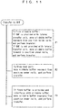
- FIG. 11 shows a transfer algorithm of an overhead travelling vehicle to transfer between the temporary storage apparatus.
- a slidable buffer (process PI) and the overhead travelling vehicle provided with the lateral transfer device
- the slidable buffer moves rearward from a position under the travelling rails, and the transfer is performed at a rearward position without interference with the local vehicle.
- the slidable buffer moves forward to a position under the travelling rails, and the transfer is performed at this position. Interlock in this case is the same as that for transfer between a load port.
- FIG. 12 shows an algorithm for avoiding interference between an overhead travelling vehicle and a local vehicle.
- the overhead travelling vehicle requests for transfer permission via a terminal in advance.
- the local vehicle requests for entrance permission for each of the stop positions to enter and makes a further request for transfer permission for transfer in addition to the entrance permission. For the same stop position, only one request out of the transfer request from the overhead travelling vehicle and the entrance request from the local vehicle may be permitted, and the interference between the overhead travelling vehicle and the local vehicle is avoided (process P5).
- the buffer controller might be unable to recognize that the overhead travelling vehicle is performing transfer.
- This problem may be solved by making the buffer controller store in a non-volatile memory the information that the overhead travelling vehicle is performing transfer, however, this problem may be more reliably solved by detecting the hoist of the overhead travelling vehicle, a carrier raised or lowered, or the like by the optical sensors 20 shown in FIG. 1 . Therefore, if the hoist or the like is detected, the entrance of the local vehicle to the detected stop position is prohibited (process P6).
- the local vehicle is configured and programmed to make a request for entrance for each of the stop positions.
- the buffer controller is configured and programmed not to permit transfer by the overhead travelling vehicle regarding positions already permitted to enter to the local vehicle (process P7). Note that regarding transfer between slidable buffers not under the travelling rails 8,8 shown in FIG. 1 , no interference will occur with the local vehicle. Therefore, the interfere avoidance process is not necessary (process P8).
- the temporary storage apparatus 2 may be supported from a ceiling 44 of the cleanroom by pillars 41 and connection portions 42, and the trestles 24 may be omitted.
- Reference numeral 43 denotes a pillar of the travelling rails 4 for the overhead travelling vehicle 30.
Landscapes
- Container, Conveyance, Adherence, Positioning, Of Wafer (AREA)
- Warehouses Or Storage Devices (AREA)
- Control Of Position, Course, Altitude, Or Attitude Of Moving Bodies (AREA)
Claims (7)
- Appareil de stockage temporaire pour stocker temporairement des chariots (18) entre un véhicule à déplacement aérien (30) se déplaçant le long d'un premier rail de déplacement (4) et un orifice de chargement (16) d'un équipement (6), l'appareil de stockage temporaire comprenant:un véhicule local (10) pourvu d'un élévateur configuré pour élever et abaisser un chariot (18) et configuré pour se déplacer;un deuxième rail de déplacement (8) pour le véhicule local (10) prévu au-dessous du premier rail de déplacement (4) pour le véhicule à déplacement aérien (30) et s'étendant vers une zone au-dessus de l'orifice de chargement (16);au moins un tampon coulissant (12) configuré pour y supporter un chariot (18) et pour coulisser entre une première position au-dessous du deuxième rail de déplacement (8) pour le véhicule local (10) et une deuxième position, séparée latéralement de la première position, au-dessous du deuxième rail de déplacement (8) pour le véhicule local (10); etun moyen de commande (92) configuré pour commander le véhicule local (10) et le tampon coulissant (12),l'appareil étant caractérisé par le fait quele deuxième rail de déplacement (8) pour le véhicule local (10) est configuré de manière à s'étendre de la zone au-dessus de l'orifice de chargement (16) à une position d'attente du véhicule local (10) décalée de la zone au-dessus de l'orifice de chargement (16),dans lequel le véhicule local (10) est configuré pour attendre à ladite position d'attente,dans lequel le tampon coulissant (12) comprend une base (70) et un socle mobile (72) configuré pour se déplacer en avant de la base (70) à une position au-dessous du deuxième rail de déplacement (8) pour le véhicule local (10),dans lequel ladite base (70) est fixée à une position séparée latéralement de la première position au-dessous du deuxième rail de déplacement (8) pour le véhicule local (10),dans lequel sont prévus un premier capteur (83) configuré pour détecter que le socle (72) est situé à la première position au-dessous du deuxième rail de déplacement (8) pour le véhicule local (10) et un deuxième capteur (84) configuré pour détecter que le socle (72) est situé à une position au-dessus de la base (70), etdans lequel ledit moyen de commande (92) est configuré et programmé pour permettre que le véhicule à déplacement aérien (30) et le véhicule local (10) transfèrent un chariot (18) vers le tampon coulissant (12) selon une position détectée du socle (72).
- Appareil de stockage temporaire selon la revendication 1, dans lequel la première position du tampon coulissant (12) est située au-dessus de l'orifice de chargement (16).
- Appareil de stockage temporaire selon la revendication 2, comprenant par ailleurs
un tampon fixe (14) configuré pour y supporter un chariot (18) et prévu à une position au-dessous du deuxième rail de déplacement (8) pour le véhicule local (10), et non pas au-dessus de l'orifice de chargement (16), et
dans lequel le tampon fixe (14) est disposé dans une zone au-dessous de ladite position d'attente. - Appareil de stockage temporaire selon l'une quelconque des revendications 1 à 3,
dans lequel est ouvert, à ladite deuxième position séparée latéralement de la position au-dessous du deuxième rail de déplacement (8) pour le véhicule local (10), un espace au-dessus dudit tampon coulissant (12), et
dans lequel le véhicule à déplacement aérien (30), qui est pourvu d'un élévateur (34, 35, 36) destiné à élever et abaisser un chariot (18) et avec un mécanisme de transfert latéral (33) destiné à transférer latéralement l'élévateur (34, 35, 36), transfère un chariot (18) entre le tampon coulissant (12) par le mécanisme de transfert latéral (33) et l'élévateur (34, 35, 36) à travers ledit espace ouvert. - Appareil de stockage temporaire selon l'une quelconque des revendications 1 à 4,
dans lequel ledit tampon coulissant (12) comprend un premier tampon coulissant configuré pour coulisser vers un côté latéral du deuxième rail de déplacement (8) pour le véhicule local (10) et un deuxième tampon coulissant configuré pour glisser vers l'autre côté latéral du deuxième rail mobile (8). - Appareil de stockage temporaire selon l'une quelconque des revendications 1 à 5,
dans lequel le socle (72) est pourvu d'un troisième capteur (75) configuré pour détecter si est présent un chariot (18), et
dans lequel le moyen de commande (92) est configuré et programmé pour permettre que les véhicules à déplacement aérien (30) et le véhicule local (10) transfèrent un chariot (18) vers le tampon coulissant (12) en fonction de si est présent un chariot (18). - Procédé de stockage temporaire de chariots (18) entre un véhicule à déplacement aérien (30) se déplaçant le long d'un premier rail de déplacement (4) et un orifice de chargement (16) d'un équipement (6) à l'aide d'un appareil de stockage temporaire, ledit appareil de stockage temporaire comprenant:un véhicule local (10) pourvu d'un élévateur configuré pour élever et abaisser un chariot (18) et configuré pour se déplacer;un deuxième rail de déplacement (8) pour le véhicule local (10) prévu au-dessous du premier rail de déplacement (4) pour le véhicule de déplacement aérien (30) et s'étendant vers une zone au-dessus de l'orifice de chargement (16);au moins un tampon coulissant (12) configuré pour y supporter un chariot (18) et pour coulisser entre une première position au-dessous du deuxième rail de déplacement (8) pour le véhicule local (10) et au-dessus de l'orifice de chargement (16) et une deuxième position, séparée latéralement de la première position, au-dessous du deuxième rail de déplacement (8) pour le véhicule local (10); etun moyen de commande (92) configuré pour commander le véhicule local (10) et le tampon coulissant (12),dans lequel le deuxième rail de déplacement (8) pour le véhicule local (10) s'étend de la zone au-dessus de l'orifice de chargement (16) à une position d'attente pour le véhicule local (10) décalée de la zone au-dessus de l'orifice de chargement (16),dans lequel le tampon coulissant (12) comprend une base (70) et un socle mobile (72) configuré pour se déplacer en avant de la base (70) à une position au-dessous du deuxième rail de déplacement (8) pour le véhicule local (10),dans lequel ladite base (70) est fixée en une position séparée latéralement de la première position au-dessous du deuxième rail de déplacement (8) pour le véhicule local (10),dans lequel sont prévus un premier capteur (83) configuré pour détecter que le socle (72) est situé à la première position au-dessous du deuxième rail de déplacement (8) pour le véhicule local (10) et un deuxième capteur (84) configuré pour détecter que le socle (72) est situé à une position au-dessus de la base (70), etdans lequel ledit moyen de commande (92) est configuré et programmé pour permettre que le véhicule à déplacement aérien (30) et le véhicule local (10) transfèrent un chariot (18) vers le tampon coulissant (12) selon une position détectée du socle (72),le procédé comprenant les étapes consistant à:commander le tampon coulissant (12), par le moyen de commande (92), pour se déplacer en arrière de la première position au-dessous du deuxième rail de déplacement (8) et au-dessus de l'orifice de chargement (16) à la deuxième position séparée latéralement, et commander le véhicule à déplacement aérien (30) ou le véhicule local (10) pour transférer un chariot (18) vers l'orifice de chargement (16);commander le tampon coulissant (12), par le moyen de commande (92), pour se déplacer en avant de la deuxième position séparée latéralement vers les positions au-dessous du deuxième rail de déplacement (8) et au-dessus de l'orifice de chargement (16), et commander le véhicule à déplacement aérien (30) ou le véhicule local (10) pour transférer un chariot (18) vers le tampon coulissant (12); etcommander le véhicule local (10) pour qu'il attende à la position d'attente.
Applications Claiming Priority (2)
| Application Number | Priority Date | Filing Date | Title |
|---|---|---|---|
| JP2014126012 | 2014-06-19 | ||
| PCT/JP2015/062938 WO2015194264A1 (fr) | 2014-06-19 | 2015-04-30 | Dispositif de mise en réserve de chariot et procédé de mise en réserve |
Publications (3)
| Publication Number | Publication Date |
|---|---|
| EP3159923A1 EP3159923A1 (fr) | 2017-04-26 |
| EP3159923A4 EP3159923A4 (fr) | 2018-02-21 |
| EP3159923B1 true EP3159923B1 (fr) | 2021-06-16 |
Family
ID=54935259
Family Applications (1)
| Application Number | Title | Priority Date | Filing Date |
|---|---|---|---|
| EP15810356.4A Active EP3159923B1 (fr) | 2014-06-19 | 2015-04-30 | Dispositif de mise en réserve de chariot et procédé de mise en réserve |
Country Status (6)
| Country | Link |
|---|---|
| US (1) | US10153189B2 (fr) |
| EP (1) | EP3159923B1 (fr) |
| JP (1) | JP6252676B2 (fr) |
| CN (1) | CN106463442B (fr) |
| TW (1) | TWI636935B (fr) |
| WO (1) | WO2015194264A1 (fr) |
Families Citing this family (13)
| Publication number | Priority date | Publication date | Assignee | Title |
|---|---|---|---|---|
| SG11201804593PA (en) * | 2015-12-08 | 2018-06-28 | Murata Machinery Ltd | Conveyance system and conveyance method |
| SG11201811443PA (en) * | 2016-06-27 | 2019-01-30 | Murata Machinery Ltd | Transport system |
| CN110248878B (zh) * | 2017-02-07 | 2021-03-12 | 村田机械株式会社 | 输送系统和输送方法 |
| CN110235235B (zh) * | 2017-04-06 | 2023-01-06 | 村田机械株式会社 | 桥式输送车系统以及示教单元 |
| JP6794946B2 (ja) * | 2017-07-11 | 2020-12-02 | 株式会社ダイフク | 物品搬送車 |
| US10622236B2 (en) * | 2017-08-30 | 2020-04-14 | Taiwan Semiconductor Manufacturing Co., Ltd. | Apparatus and method for handling wafer carrier doors |
| JP7349240B2 (ja) * | 2018-10-05 | 2023-09-22 | 東京エレクトロン株式会社 | 基板倉庫及び基板検査方法 |
| WO2020153040A1 (fr) * | 2019-01-25 | 2020-07-30 | 村田機械株式会社 | Système de stockage |
| SG11202108087XA (en) * | 2019-01-25 | 2021-08-30 | Murata Machinery Ltd | Storage system |
| WO2021220621A1 (fr) * | 2020-04-30 | 2021-11-04 | 村田機械株式会社 | Système de véhicule de transport |
| US12217991B2 (en) * | 2021-07-29 | 2025-02-04 | Taiwan Semiconductor Manufacturing Company, Ltd. | Portable robotic semiconductor pod loader |
| KR102570641B1 (ko) * | 2021-08-23 | 2023-08-25 | 허브디티(주) | 장비 전단부 모듈 툴버퍼 제어 시스템 |
| CN120613301B (zh) * | 2025-08-11 | 2025-11-04 | 苏州新施诺半导体设备有限公司 | 空中走行搬送系统及运输控制系统 |
Family Cites Families (19)
| Publication number | Priority date | Publication date | Assignee | Title |
|---|---|---|---|---|
| US20080240892A1 (en) * | 2007-03-28 | 2008-10-02 | International Business Machines Corporation | Storage buffer device for automated material handling systems |
| JP4796024B2 (ja) * | 2007-08-30 | 2011-10-19 | 東京エレクトロン株式会社 | 容器交換システム及び容器交換方法 |
| KR101015225B1 (ko) * | 2008-07-07 | 2011-02-18 | 세메스 주식회사 | 기판 처리장치 및 이의 기판 이송 방법 |
| WO2010135205A2 (fr) * | 2009-05-18 | 2010-11-25 | Crossing Automation, Inc. | Systèmes intégrés pour créer une interface avec des systèmes de stockage de boîtiers de substrat |
| US8882433B2 (en) * | 2009-05-18 | 2014-11-11 | Brooks Automation, Inc. | Integrated systems for interfacing with substrate container storage systems |
| JP5445015B2 (ja) * | 2009-10-14 | 2014-03-19 | シンフォニアテクノロジー株式会社 | キャリア移載促進装置 |
| JP5429570B2 (ja) * | 2010-03-08 | 2014-02-26 | 株式会社ダイフク | 物品搬送設備 |
| JP5229363B2 (ja) * | 2010-11-04 | 2013-07-03 | 村田機械株式会社 | 搬送システム及び搬送方法 |
| JP5382470B2 (ja) | 2010-11-04 | 2014-01-08 | 村田機械株式会社 | 搬送システム及び搬送方法 |
| US20140286733A1 (en) * | 2011-11-09 | 2014-09-25 | Sinfonia Technology Co., Ltd. | Load port and efem |
| JP5880991B2 (ja) * | 2012-06-08 | 2016-03-09 | 村田機械株式会社 | 搬送システム及び搬送システムでの物品の一時保管方法 |
| EP2878552B1 (fr) * | 2012-07-26 | 2021-01-13 | Murata Machinery, Ltd. | Système de véhicule à déplacement aérien et procédé de commande de transfert pour système de véhicule à déplacement aérien |
| SG11201407697RA (en) * | 2012-07-26 | 2015-04-29 | Murata Machinery Ltd | Overhead traveling vehicle system and control method for overhead traveling vehicle system |
| US9633879B2 (en) * | 2014-05-14 | 2017-04-25 | Murata Machinery, Ltd. | Storage system in the ceiling space and storage method for goods thereby |
| US10186442B2 (en) * | 2014-06-19 | 2019-01-22 | Murata Machinery, Ltd | Carrier buffering device and storage method |
| CN106463441B (zh) * | 2014-06-19 | 2019-04-23 | 村田机械株式会社 | 载具的临时保管装置和临时保管方法 |
| JP6206748B6 (ja) * | 2014-06-19 | 2018-06-27 | 村田機械株式会社 | キャリアの搬送システムと搬送方法 |
| JP6048686B2 (ja) * | 2014-09-25 | 2016-12-21 | 村田機械株式会社 | 一時保管装置と搬送システム及び一時保管方法 |
| US9698036B2 (en) * | 2015-11-05 | 2017-07-04 | Lam Research Corporation | Stacked wafer cassette loading system |
-
2015
- 2015-04-30 EP EP15810356.4A patent/EP3159923B1/fr active Active
- 2015-04-30 US US15/315,675 patent/US10153189B2/en active Active
- 2015-04-30 WO PCT/JP2015/062938 patent/WO2015194264A1/fr not_active Ceased
- 2015-04-30 JP JP2016529150A patent/JP6252676B2/ja active Active
- 2015-04-30 CN CN201580029265.7A patent/CN106463442B/zh active Active
- 2015-06-16 TW TW104119410A patent/TWI636935B/zh not_active IP Right Cessation
Non-Patent Citations (1)
| Title |
|---|
| None * |
Also Published As
| Publication number | Publication date |
|---|---|
| EP3159923A1 (fr) | 2017-04-26 |
| US10153189B2 (en) | 2018-12-11 |
| CN106463442B (zh) | 2019-11-05 |
| JP6252676B2 (ja) | 2017-12-27 |
| EP3159923A4 (fr) | 2018-02-21 |
| CN106463442A (zh) | 2017-02-22 |
| JPWO2015194264A1 (ja) | 2017-04-20 |
| TWI636935B (zh) | 2018-10-01 |
| US20170200626A1 (en) | 2017-07-13 |
| WO2015194264A1 (fr) | 2015-12-23 |
| TW201607862A (zh) | 2016-03-01 |
Similar Documents
| Publication | Publication Date | Title |
|---|---|---|
| EP3159923B1 (fr) | Dispositif de mise en réserve de chariot et procédé de mise en réserve | |
| EP3159922B1 (fr) | Système de transport de chariot et procédé de transport | |
| US9548230B2 (en) | Temporary storage device, transport system, and temporary storage method | |
| EP2450296B1 (fr) | Système et procédé pour transporter un article entre des dispositifs de traitement | |
| KR102276842B1 (ko) | 층간 반송 설비 | |
| CN104891081B (zh) | 物品支撑装置 | |
| JPWO2015194267A6 (ja) | キャリアの搬送システムと搬送方法 | |
| US20170233187A1 (en) | Temporary storage system, conveyance system using same, and temporary storage method | |
| EP3159921B1 (fr) | Dispositif tampon de support et procédé de stockage | |
| EP3159920B1 (fr) | Dispositif de protection de support et procédé de protection |
Legal Events
| Date | Code | Title | Description |
|---|---|---|---|
| STAA | Information on the status of an ep patent application or granted ep patent |
Free format text: STATUS: THE INTERNATIONAL PUBLICATION HAS BEEN MADE |
|
| PUAI | Public reference made under article 153(3) epc to a published international application that has entered the european phase |
Free format text: ORIGINAL CODE: 0009012 |
|
| STAA | Information on the status of an ep patent application or granted ep patent |
Free format text: STATUS: REQUEST FOR EXAMINATION WAS MADE |
|
| 17P | Request for examination filed |
Effective date: 20161207 |
|
| AK | Designated contracting states |
Kind code of ref document: A1 Designated state(s): AL AT BE BG CH CY CZ DE DK EE ES FI FR GB GR HR HU IE IS IT LI LT LU LV MC MK MT NL NO PL PT RO RS SE SI SK SM TR |
|
| AX | Request for extension of the european patent |
Extension state: BA ME |
|
| DAV | Request for validation of the european patent (deleted) | ||
| DAX | Request for extension of the european patent (deleted) | ||
| A4 | Supplementary search report drawn up and despatched |
Effective date: 20180122 |
|
| RIC1 | Information provided on ipc code assigned before grant |
Ipc: H01L 21/677 20060101AFI20180116BHEP |
|
| GRAP | Despatch of communication of intention to grant a patent |
Free format text: ORIGINAL CODE: EPIDOSNIGR1 |
|
| STAA | Information on the status of an ep patent application or granted ep patent |
Free format text: STATUS: GRANT OF PATENT IS INTENDED |
|
| INTG | Intention to grant announced |
Effective date: 20201221 |
|
| GRAJ | Information related to disapproval of communication of intention to grant by the applicant or resumption of examination proceedings by the epo deleted |
Free format text: ORIGINAL CODE: EPIDOSDIGR1 |
|
| STAA | Information on the status of an ep patent application or granted ep patent |
Free format text: STATUS: REQUEST FOR EXAMINATION WAS MADE |
|
| GRAP | Despatch of communication of intention to grant a patent |
Free format text: ORIGINAL CODE: EPIDOSNIGR1 |
|
| STAA | Information on the status of an ep patent application or granted ep patent |
Free format text: STATUS: GRANT OF PATENT IS INTENDED |
|
| INTC | Intention to grant announced (deleted) | ||
| INTG | Intention to grant announced |
Effective date: 20210323 |
|
| GRAS | Grant fee paid |
Free format text: ORIGINAL CODE: EPIDOSNIGR3 |
|
| GRAA | (expected) grant |
Free format text: ORIGINAL CODE: 0009210 |
|
| STAA | Information on the status of an ep patent application or granted ep patent |
Free format text: STATUS: THE PATENT HAS BEEN GRANTED |
|
| AK | Designated contracting states |
Kind code of ref document: B1 Designated state(s): AL AT BE BG CH CY CZ DE DK EE ES FI FR GB GR HR HU IE IS IT LI LT LU LV MC MK MT NL NO PL PT RO RS SE SI SK SM TR |
|
| REG | Reference to a national code |
Ref country code: GB Ref legal event code: FG4D |
|
| REG | Reference to a national code |
Ref country code: CH Ref legal event code: EP |
|
| REG | Reference to a national code |
Ref country code: DE Ref legal event code: R096 Ref document number: 602015070484 Country of ref document: DE |
|
| REG | Reference to a national code |
Ref country code: AT Ref legal event code: REF Ref document number: 1403036 Country of ref document: AT Kind code of ref document: T Effective date: 20210715 |
|
| REG | Reference to a national code |
Ref country code: IE Ref legal event code: FG4D |
|
| REG | Reference to a national code |
Ref country code: LT Ref legal event code: MG9D |
|
| PG25 | Lapsed in a contracting state [announced via postgrant information from national office to epo] |
Ref country code: LT Free format text: LAPSE BECAUSE OF FAILURE TO SUBMIT A TRANSLATION OF THE DESCRIPTION OR TO PAY THE FEE WITHIN THE PRESCRIBED TIME-LIMIT Effective date: 20210616 Ref country code: FI Free format text: LAPSE BECAUSE OF FAILURE TO SUBMIT A TRANSLATION OF THE DESCRIPTION OR TO PAY THE FEE WITHIN THE PRESCRIBED TIME-LIMIT Effective date: 20210616 Ref country code: BG Free format text: LAPSE BECAUSE OF FAILURE TO SUBMIT A TRANSLATION OF THE DESCRIPTION OR TO PAY THE FEE WITHIN THE PRESCRIBED TIME-LIMIT Effective date: 20210916 Ref country code: HR Free format text: LAPSE BECAUSE OF FAILURE TO SUBMIT A TRANSLATION OF THE DESCRIPTION OR TO PAY THE FEE WITHIN THE PRESCRIBED TIME-LIMIT Effective date: 20210616 |
|
| REG | Reference to a national code |
Ref country code: AT Ref legal event code: MK05 Ref document number: 1403036 Country of ref document: AT Kind code of ref document: T Effective date: 20210616 |
|
| REG | Reference to a national code |
Ref country code: NL Ref legal event code: MP Effective date: 20210616 |
|
| PG25 | Lapsed in a contracting state [announced via postgrant information from national office to epo] |
Ref country code: NO Free format text: LAPSE BECAUSE OF FAILURE TO SUBMIT A TRANSLATION OF THE DESCRIPTION OR TO PAY THE FEE WITHIN THE PRESCRIBED TIME-LIMIT Effective date: 20210916 Ref country code: RS Free format text: LAPSE BECAUSE OF FAILURE TO SUBMIT A TRANSLATION OF THE DESCRIPTION OR TO PAY THE FEE WITHIN THE PRESCRIBED TIME-LIMIT Effective date: 20210616 Ref country code: SE Free format text: LAPSE BECAUSE OF FAILURE TO SUBMIT A TRANSLATION OF THE DESCRIPTION OR TO PAY THE FEE WITHIN THE PRESCRIBED TIME-LIMIT Effective date: 20210616 Ref country code: LV Free format text: LAPSE BECAUSE OF FAILURE TO SUBMIT A TRANSLATION OF THE DESCRIPTION OR TO PAY THE FEE WITHIN THE PRESCRIBED TIME-LIMIT Effective date: 20210616 Ref country code: GR Free format text: LAPSE BECAUSE OF FAILURE TO SUBMIT A TRANSLATION OF THE DESCRIPTION OR TO PAY THE FEE WITHIN THE PRESCRIBED TIME-LIMIT Effective date: 20210917 |
|
| PG25 | Lapsed in a contracting state [announced via postgrant information from national office to epo] |
Ref country code: SM Free format text: LAPSE BECAUSE OF FAILURE TO SUBMIT A TRANSLATION OF THE DESCRIPTION OR TO PAY THE FEE WITHIN THE PRESCRIBED TIME-LIMIT Effective date: 20210616 Ref country code: SK Free format text: LAPSE BECAUSE OF FAILURE TO SUBMIT A TRANSLATION OF THE DESCRIPTION OR TO PAY THE FEE WITHIN THE PRESCRIBED TIME-LIMIT Effective date: 20210616 Ref country code: EE Free format text: LAPSE BECAUSE OF FAILURE TO SUBMIT A TRANSLATION OF THE DESCRIPTION OR TO PAY THE FEE WITHIN THE PRESCRIBED TIME-LIMIT Effective date: 20210616 Ref country code: CZ Free format text: LAPSE BECAUSE OF FAILURE TO SUBMIT A TRANSLATION OF THE DESCRIPTION OR TO PAY THE FEE WITHIN THE PRESCRIBED TIME-LIMIT Effective date: 20210616 Ref country code: ES Free format text: LAPSE BECAUSE OF FAILURE TO SUBMIT A TRANSLATION OF THE DESCRIPTION OR TO PAY THE FEE WITHIN THE PRESCRIBED TIME-LIMIT Effective date: 20210616 Ref country code: NL Free format text: LAPSE BECAUSE OF FAILURE TO SUBMIT A TRANSLATION OF THE DESCRIPTION OR TO PAY THE FEE WITHIN THE PRESCRIBED TIME-LIMIT Effective date: 20210616 Ref country code: PT Free format text: LAPSE BECAUSE OF FAILURE TO SUBMIT A TRANSLATION OF THE DESCRIPTION OR TO PAY THE FEE WITHIN THE PRESCRIBED TIME-LIMIT Effective date: 20211018 Ref country code: RO Free format text: LAPSE BECAUSE OF FAILURE TO SUBMIT A TRANSLATION OF THE DESCRIPTION OR TO PAY THE FEE WITHIN THE PRESCRIBED TIME-LIMIT Effective date: 20210616 Ref country code: AT Free format text: LAPSE BECAUSE OF FAILURE TO SUBMIT A TRANSLATION OF THE DESCRIPTION OR TO PAY THE FEE WITHIN THE PRESCRIBED TIME-LIMIT Effective date: 20210616 |
|
| PG25 | Lapsed in a contracting state [announced via postgrant information from national office to epo] |
Ref country code: PL Free format text: LAPSE BECAUSE OF FAILURE TO SUBMIT A TRANSLATION OF THE DESCRIPTION OR TO PAY THE FEE WITHIN THE PRESCRIBED TIME-LIMIT Effective date: 20210616 |
|
| REG | Reference to a national code |
Ref country code: DE Ref legal event code: R097 Ref document number: 602015070484 Country of ref document: DE |
|
| PLBE | No opposition filed within time limit |
Free format text: ORIGINAL CODE: 0009261 |
|
| STAA | Information on the status of an ep patent application or granted ep patent |
Free format text: STATUS: NO OPPOSITION FILED WITHIN TIME LIMIT |
|
| PG25 | Lapsed in a contracting state [announced via postgrant information from national office to epo] |
Ref country code: DK Free format text: LAPSE BECAUSE OF FAILURE TO SUBMIT A TRANSLATION OF THE DESCRIPTION OR TO PAY THE FEE WITHIN THE PRESCRIBED TIME-LIMIT Effective date: 20210616 |
|
| 26N | No opposition filed |
Effective date: 20220317 |
|
| PG25 | Lapsed in a contracting state [announced via postgrant information from national office to epo] |
Ref country code: AL Free format text: LAPSE BECAUSE OF FAILURE TO SUBMIT A TRANSLATION OF THE DESCRIPTION OR TO PAY THE FEE WITHIN THE PRESCRIBED TIME-LIMIT Effective date: 20210616 |
|
| PG25 | Lapsed in a contracting state [announced via postgrant information from national office to epo] |
Ref country code: IT Free format text: LAPSE BECAUSE OF FAILURE TO SUBMIT A TRANSLATION OF THE DESCRIPTION OR TO PAY THE FEE WITHIN THE PRESCRIBED TIME-LIMIT Effective date: 20210616 |
|
| REG | Reference to a national code |
Ref country code: CH Ref legal event code: PL |
|
| GBPC | Gb: european patent ceased through non-payment of renewal fee |
Effective date: 20220430 |
|
| REG | Reference to a national code |
Ref country code: BE Ref legal event code: MM Effective date: 20220430 |
|
| PG25 | Lapsed in a contracting state [announced via postgrant information from national office to epo] |
Ref country code: MC Free format text: LAPSE BECAUSE OF FAILURE TO SUBMIT A TRANSLATION OF THE DESCRIPTION OR TO PAY THE FEE WITHIN THE PRESCRIBED TIME-LIMIT Effective date: 20210616 Ref country code: LU Free format text: LAPSE BECAUSE OF NON-PAYMENT OF DUE FEES Effective date: 20220430 Ref country code: LI Free format text: LAPSE BECAUSE OF NON-PAYMENT OF DUE FEES Effective date: 20220430 Ref country code: GB Free format text: LAPSE BECAUSE OF NON-PAYMENT OF DUE FEES Effective date: 20220430 Ref country code: FR Free format text: LAPSE BECAUSE OF NON-PAYMENT OF DUE FEES Effective date: 20220430 Ref country code: CH Free format text: LAPSE BECAUSE OF NON-PAYMENT OF DUE FEES Effective date: 20220430 |
|
| PG25 | Lapsed in a contracting state [announced via postgrant information from national office to epo] |
Ref country code: BE Free format text: LAPSE BECAUSE OF NON-PAYMENT OF DUE FEES Effective date: 20220430 |
|
| PG25 | Lapsed in a contracting state [announced via postgrant information from national office to epo] |
Ref country code: IE Free format text: LAPSE BECAUSE OF NON-PAYMENT OF DUE FEES Effective date: 20220430 |
|
| PG25 | Lapsed in a contracting state [announced via postgrant information from national office to epo] |
Ref country code: HU Free format text: LAPSE BECAUSE OF FAILURE TO SUBMIT A TRANSLATION OF THE DESCRIPTION OR TO PAY THE FEE WITHIN THE PRESCRIBED TIME-LIMIT; INVALID AB INITIO Effective date: 20150430 |
|
| PG25 | Lapsed in a contracting state [announced via postgrant information from national office to epo] |
Ref country code: MK Free format text: LAPSE BECAUSE OF FAILURE TO SUBMIT A TRANSLATION OF THE DESCRIPTION OR TO PAY THE FEE WITHIN THE PRESCRIBED TIME-LIMIT Effective date: 20210616 Ref country code: CY Free format text: LAPSE BECAUSE OF FAILURE TO SUBMIT A TRANSLATION OF THE DESCRIPTION OR TO PAY THE FEE WITHIN THE PRESCRIBED TIME-LIMIT Effective date: 20210616 |
|
| PG25 | Lapsed in a contracting state [announced via postgrant information from national office to epo] |
Ref country code: MT Free format text: LAPSE BECAUSE OF FAILURE TO SUBMIT A TRANSLATION OF THE DESCRIPTION OR TO PAY THE FEE WITHIN THE PRESCRIBED TIME-LIMIT Effective date: 20210616 |
|
| PGFP | Annual fee paid to national office [announced via postgrant information from national office to epo] |
Ref country code: DE Payment date: 20250319 Year of fee payment: 11 |
|
| REG | Reference to a national code |
Ref country code: DE Ref legal event code: R079 Ref document number: 602015070484 Country of ref document: DE Free format text: PREVIOUS MAIN CLASS: H01L0021677000 Ipc: H10P0072300000 |
|
| PG25 | Lapsed in a contracting state [announced via postgrant information from national office to epo] |
Ref country code: TR Free format text: LAPSE BECAUSE OF FAILURE TO SUBMIT A TRANSLATION OF THE DESCRIPTION OR TO PAY THE FEE WITHIN THE PRESCRIBED TIME-LIMIT Effective date: 20210616 |