EP3159971A1 - Klemmensockel mit befestigungsstruktur - Google Patents
Klemmensockel mit befestigungsstruktur Download PDFInfo
- Publication number
- EP3159971A1 EP3159971A1 EP15190805.0A EP15190805A EP3159971A1 EP 3159971 A1 EP3159971 A1 EP 3159971A1 EP 15190805 A EP15190805 A EP 15190805A EP 3159971 A1 EP3159971 A1 EP 3159971A1
- Authority
- EP
- European Patent Office
- Prior art keywords
- terminal base
- block
- fastening structure
- hook element
- accommodating space
- Prior art date
- Legal status (The legal status is an assumption and is not a legal conclusion. Google has not performed a legal analysis and makes no representation as to the accuracy of the status listed.)
- Granted
Links
Images




Classifications
-
- H—ELECTRICITY
- H01—ELECTRIC ELEMENTS
- H01R—ELECTRICALLY-CONDUCTIVE CONNECTIONS; STRUCTURAL ASSOCIATIONS OF A PLURALITY OF MUTUALLY-INSULATED ELECTRICAL CONNECTING ELEMENTS; COUPLING DEVICES; CURRENT COLLECTORS
- H01R4/00—Electrically-conductive connections between two or more conductive members in direct contact, i.e. touching one another; Means for effecting or maintaining such contact; Electrically-conductive connections having two or more spaced connecting locations for conductors and using contact members penetrating insulation
- H01R4/28—Clamped connections, spring connections
- H01R4/48—Clamped connections, spring connections utilising a spring, clip, or other resilient member
- H01R4/4809—Clamped connections, spring connections utilising a spring, clip, or other resilient member using a leaf spring to bias the conductor toward the busbar
- H01R4/48185—Clamped connections, spring connections utilising a spring, clip, or other resilient member using a leaf spring to bias the conductor toward the busbar adapted for axial insertion of a wire end
- H01R4/4819—Clamped connections, spring connections utilising a spring, clip, or other resilient member using a leaf spring to bias the conductor toward the busbar adapted for axial insertion of a wire end the spring shape allowing insertion of the conductor end when the spring is unbiased
- H01R4/4821—Single-blade spring
-
- H—ELECTRICITY
- H01—ELECTRIC ELEMENTS
- H01R—ELECTRICALLY-CONDUCTIVE CONNECTIONS; STRUCTURAL ASSOCIATIONS OF A PLURALITY OF MUTUALLY-INSULATED ELECTRICAL CONNECTING ELEMENTS; COUPLING DEVICES; CURRENT COLLECTORS
- H01R4/00—Electrically-conductive connections between two or more conductive members in direct contact, i.e. touching one another; Means for effecting or maintaining such contact; Electrically-conductive connections having two or more spaced connecting locations for conductors and using contact members penetrating insulation
- H01R4/28—Clamped connections, spring connections
- H01R4/48—Clamped connections, spring connections utilising a spring, clip, or other resilient member
- H01R4/4809—Clamped connections, spring connections utilising a spring, clip, or other resilient member using a leaf spring to bias the conductor toward the busbar
- H01R4/4828—Spring-activating arrangements mounted on or integrally formed with the spring housing
- H01R4/4833—Sliding arrangements, e.g. sliding button
-
- H—ELECTRICITY
- H01—ELECTRIC ELEMENTS
- H01R—ELECTRICALLY-CONDUCTIVE CONNECTIONS; STRUCTURAL ASSOCIATIONS OF A PLURALITY OF MUTUALLY-INSULATED ELECTRICAL CONNECTING ELEMENTS; COUPLING DEVICES; CURRENT COLLECTORS
- H01R4/00—Electrically-conductive connections between two or more conductive members in direct contact, i.e. touching one another; Means for effecting or maintaining such contact; Electrically-conductive connections having two or more spaced connecting locations for conductors and using contact members penetrating insulation
- H01R4/28—Clamped connections, spring connections
- H01R4/48—Clamped connections, spring connections utilising a spring, clip, or other resilient member
- H01R4/4809—Clamped connections, spring connections utilising a spring, clip, or other resilient member using a leaf spring to bias the conductor toward the busbar
- H01R4/4828—Spring-activating arrangements mounted on or integrally formed with the spring housing
- H01R4/4835—Mechanically bistable arrangements, e.g. locked by the housing when the spring is biased
-
- H—ELECTRICITY
- H01—ELECTRIC ELEMENTS
- H01R—ELECTRICALLY-CONDUCTIVE CONNECTIONS; STRUCTURAL ASSOCIATIONS OF A PLURALITY OF MUTUALLY-INSULATED ELECTRICAL CONNECTING ELEMENTS; COUPLING DEVICES; CURRENT COLLECTORS
- H01R13/00—Details of coupling devices of the kinds covered by groups H01R12/70 or H01R24/00 - H01R33/00
- H01R13/62—Means for facilitating engagement or disengagement of coupling parts or for holding them in engagement
- H01R13/639—Additional means for holding or locking coupling parts together, after engagement, e.g. separate keylock, retainer strap
-
- H—ELECTRICITY
- H01—ELECTRIC ELEMENTS
- H01R—ELECTRICALLY-CONDUCTIVE CONNECTIONS; STRUCTURAL ASSOCIATIONS OF A PLURALITY OF MUTUALLY-INSULATED ELECTRICAL CONNECTING ELEMENTS; COUPLING DEVICES; CURRENT COLLECTORS
- H01R4/00—Electrically-conductive connections between two or more conductive members in direct contact, i.e. touching one another; Means for effecting or maintaining such contact; Electrically-conductive connections having two or more spaced connecting locations for conductors and using contact members penetrating insulation
- H01R4/28—Clamped connections, spring connections
- H01R4/48—Clamped connections, spring connections utilising a spring, clip, or other resilient member
- H01R4/4809—Clamped connections, spring connections utilising a spring, clip, or other resilient member using a leaf spring to bias the conductor toward the busbar
- H01R4/484—Spring housing details
Definitions
- the present invention relates to a terminal base and, in particular, to a terminal base allowing quick wiring or quick cable replacement.
- Connecting elements for signal transmission are commonly used, which are, for example, terminal base structures used in an electronic device for connecting signal wires.
- terminal base structures used in an electronic device for connecting signal wires.
- signal wires/cables from different electric components it is required that signal wires/cables from different electric components be connected to one another to allow signal transmission among the same.
- a maintenance staff has to press a press block by a screwdriver or other similar hand tool with one hand and insert a signal wire/cable with the other hand to make wiring.
- Such wiring therefore causes troubles and inconvenience to the maintenance staff.
- wiring is extremely time and labor consuming.
- the aim of this disclosure is to solve the above-mentioned problems to improve wiring in the conventional terminal base, which industry in related fields has attempted to solve.
- the present invention provides a terminal base having a fastening structure for collaborating with a cable having a core.
- the terminal base includes a body, a conductive terminal, a metal elastic element, and a press block.
- the body includes an accommodating space, a wiring hole, a receiving hole, and a hook element disposed adjacent to the receiving hole.
- the wiring hole and the receiving hole communicate with the accommodating space.
- the hook element is elastically connected to the body.
- the conductive terminal is disposed in the accommodating space.
- the conductive terminal includes two leads protruding outside of the body.
- the metal elastic element is disposed inside the accommodating space.
- the metal elastic element includes a contact end and a movable end. The contact end is in contact with the conductive terminal.
- the movable end is elastically disposed inside the accommodating space.
- the press block is movably disposed in the receiving hole. The press block presses the movable end of the metal elastic element to be engaged with the hook element.
- the body further includes a stopper, and the stopper is fixed inside the accommodating space to position the conductive terminal.
- the hook element includes an extension rod and a clasp portion connected to the extension rod, and the press block includes an engagement point at one side for engaged with the clasp portion.
- the present invention provides a terminal base 100 having a fastening structure for collaborating with a cable 10 having a core 12.
- the cable 10 includes an electric wire, a double insulated wire, other suitable signal wires, or etc.
- the terminal base 100 includes a body 110, a conductive terminal 200, a metal elastic element 300, and a press block 170.
- the body 110 includes an accommodating space 120, a wiring hole 130, a receiving hole 140, and a hook element 150 disposed adjacent to the receiving hole 140.
- the wiring hole 130 and the receiving hole 140 communicates with the accommodating space 120, and the hook element 150 is elastically connected to the body 110.
- the conductive terminal 200 made of copper or alloy thereof is disposed in the accommodating space 120.
- the conductive terminal 200 includes two leads 210 protruding outside of the body 110.
- the metal elastic element 300 is disposed inside the accommodating space 120.
- the metal elastic element 300 includes a contact end 310 and a movable end 320.
- the conductive terminal 200 further includes a protrusion 220, and the contact end 310 includes a positioning hole 312 for the protrusion 220 to be positioned therein, whereby the contact end 310 is in contact with the conductive terminal 200, and the movable end 320 is elastically disposed inside the accommodating space 120.
- the body 110 further includes a stopper 160, and the stopper 160 is fixed inside the accommodating space 120 to position the conductive terminal 200.
- one side surface of the stopper 160 corresponds in shape to the contact end 310 to limit movement of the contact end 310.
- the body 110 further provides a narrow cavity 122.
- the narrow cavity 122 and the accommodating space 120 communicate with each other and respectively accommodate the metal elastic element 300 and the conductive terminal 200. In the embodiment shown in Figs. 5 and 6 , it is preferable that a portion of the narrow cavity 122 fixes the metal elastic element 300 and the conductive terminal 200 at the same time to ensure smooth signal transmission.
- the body 110 further includes two openings 124 and a recess 126.
- the two openings 124 communicate with the narrow cavity 122.
- the two leads 210 protrude outside of the two openings and are positioned therein.
- the conductive terminal 200 includes an extension portion 240 positioned in the recess 126 and a bend portion 230 disposed in the accommodating space 120.
- the extension portion 240 and the bend portion 230 are respectively at two ends of the conductive terminal 200.
- the bend portion 230 further includes a barb portion 232 toward the accommodating space 120 for securing the core 12.
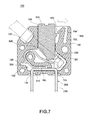
- the press block 170 is movably disposed in the receiving hole 140, so the press block 170 can press the movable end 320 of the metal elastic element 300 to be engaged with the hook element 150.
- the hook element 150 integrally formed with the body 110 further includes an extension rod 152 and a clasp portion 154 connected to the extension rod 152.
- the press block 170 includes an engagement point 172 at one side for engaged with the clasp portion 154.
- the clasp portion 154 includes a first inclined surface 156.
- the press block 170 includes a second inclined surface 178 disposed corresponding to the first inclined surface 156.
- the press block 170 keeps pressing the movable end 320 of the metal elastic element 300 to allow insertion of the core 12 of the cable 10 via the wiring hole 130, so that the core 12 contacts the movable end 320 and the bend portion 230 of the conductive terminal 200.
- cable arrangement is completed after stopping pressing the press block 170, and the inserted core 12 is clamped by the metal elastic element 300 and the conductive terminal 200.
- it is required to move the hook element 150 by, for example, a finger or a screwdriver, so as to release the clasp portion 154 from the restriction of the engagement point 172.
- the press block 170 returns to an original position, and the core 12 is clamped between the movable end 320 of the metal elastic element 300 and the barb portion 232 of the bend portion 230.
- the present invention obviates the necessity of pressing the press block 170 with one hand and inserting the cable 10 with the other hand as the conventional technique does and makes inserting the cable 10 (i.e. cable arrangement) time and labor saving in a flexible way. Furthermore, after completely inserting the cable 10, if the cable 10 is misarranged, the misarranged cable 10 can be taken out quickly and conveniently for replacement/rearrangement.
- Figs. 9 and 10 are an exploded view and a perspective view according to a second embodiment of the present invention.
- a plurality of the terminal bases 100 and a side cover 190 are assembled together.
- one side of the side cover 190 includes a plurality of assembly holes 192
- one side of the body 110 includes a plurality of assembly pillars 180 for assembled in the assembly holes 192.
- Each terminal base 100 further includes a plurality of the assembly holes 192 (not illustrated) in the other side opposite to the assembly pillars 180, so that the terminal bases 100 can be assembled together.
- the engagement of the press block 170 with the clasp element 150 allows the cables to be inserted quickly and conveniently, thereby making the insertion operation time and labor saving in a flexible way. Besides, in this embodiment, if any cable is misarranged, the misarranged cable 10 can be taken out quickly and conveniently for replacement/rearrangement.
- the press block 170 includes two engagement points 172 spaced apart from each other and an inclined recess 174 between the two engagement points 172.
- the hook portion 150 of the body 110 includes an extension rod 152 and two clasp portions 154 connected to the extension rod 152, and each of the engagement points 172 is disposed corresponding to each of the clasp portions 154 to be engaged with the same.
- the hook element 150 is a T-shaped structure, and each of the clasp portions 154 is disposed at two ends of a head portion of the T-shaped structure.
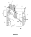
- the press block 170 further includes a limiting block 176, and the hook element 150 further includes a contact block 158 disposed corresponding to the limiting block 176, so as to limit the press block 170 from moving toward the accommodating space 120 from the receiving hole 140.
- the extension rod 152 of the hook element 150 further includes a step block 151 to limit or prevent hand tools, like preventing the screwdriver from being inserted too deep into the receiving hole 140 or the accommodating space 120.
- the step block 151 is disposed between the contact block 158 and two clasp portions 154, and the contact block 158 protrudes toward the receiving hole 140 further than the step block 151.
- a hand tool such as the screwdriver can be used to reach from the inclined recess 174 and push the extension rod 152 of the hook element 150, so as to release each of the engagement points 172 from the restriction of each of the clasp portions 154, and thereby the press block 170 is ejected and the misarranged cable 10 can be taken out quickly and conveniently for replacement or rearrangement.
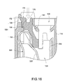
- the hook element 150 has an extension rod 152 and a fastening hole 159 formed on the extension rod 152, and the press block 170 includes an engagement point 172 at one side for engagement with the fastening hole 159.
- the press block 170 further includes a limiting block 176, and the hook element 150 includes a contact block 158 disposed corresponding to the limiting block 176, so as to limit the press block 170 from moving toward the accommodating space 120 from the receiving hole 140.
- a finger or a hand tool such as the screwdriver can be used to reach from the fastening hole 159 to disengage the engagement point 172 therefrom so as to eject the press block 170, and thereby the misarranged cable 10 can be taken out quickly and conveniently for replacement or rearrangement.
Landscapes
- Connections Arranged To Contact A Plurality Of Conductors (AREA)
Priority Applications (2)
| Application Number | Priority Date | Filing Date | Title |
|---|---|---|---|
| EP15190805.0A EP3159971B1 (de) | 2015-10-21 | 2015-10-21 | Klemmensockel mit befestigungsstruktur |
| EP18167585.1A EP3382807A1 (de) | 2015-10-21 | 2015-10-21 | Klemmensockel mit befestigungsstruktur |
Applications Claiming Priority (1)
| Application Number | Priority Date | Filing Date | Title |
|---|---|---|---|
| EP15190805.0A EP3159971B1 (de) | 2015-10-21 | 2015-10-21 | Klemmensockel mit befestigungsstruktur |
Related Child Applications (2)
| Application Number | Title | Priority Date | Filing Date |
|---|---|---|---|
| EP18167585.1A Division EP3382807A1 (de) | 2015-10-21 | 2015-10-21 | Klemmensockel mit befestigungsstruktur |
| EP18167585.1A Division-Into EP3382807A1 (de) | 2015-10-21 | 2015-10-21 | Klemmensockel mit befestigungsstruktur |
Publications (2)
| Publication Number | Publication Date |
|---|---|
| EP3159971A1 true EP3159971A1 (de) | 2017-04-26 |
| EP3159971B1 EP3159971B1 (de) | 2018-09-19 |
Family
ID=54337694
Family Applications (2)
| Application Number | Title | Priority Date | Filing Date |
|---|---|---|---|
| EP15190805.0A Active EP3159971B1 (de) | 2015-10-21 | 2015-10-21 | Klemmensockel mit befestigungsstruktur |
| EP18167585.1A Withdrawn EP3382807A1 (de) | 2015-10-21 | 2015-10-21 | Klemmensockel mit befestigungsstruktur |
Family Applications After (1)
| Application Number | Title | Priority Date | Filing Date |
|---|---|---|---|
| EP18167585.1A Withdrawn EP3382807A1 (de) | 2015-10-21 | 2015-10-21 | Klemmensockel mit befestigungsstruktur |
Country Status (1)
| Country | Link |
|---|---|
| EP (2) | EP3159971B1 (de) |
Cited By (6)
| Publication number | Priority date | Publication date | Assignee | Title |
|---|---|---|---|---|
| WO2018202504A1 (de) * | 2017-05-05 | 2018-11-08 | Wago Verwaltungsgesellschaft Mbh | Anschlussklemme |
| CN109216958A (zh) * | 2018-09-28 | 2019-01-15 | 广州番禺电缆集团有限公司 | 一种接线端子连接结构 |
| WO2019201550A1 (de) * | 2018-04-20 | 2019-10-24 | Phoenix Contact Gmbh & Co. Kg | Federkraftklemmanschluss und leiteranschlussklemme |
| EP3586403A1 (de) * | 2017-02-21 | 2020-01-01 | WAGO Verwaltungsgesellschaft mbH | Leiteranschlussklemme |
| DE102017116550B4 (de) * | 2016-12-13 | 2020-08-13 | Excel Cell Electronic Co., Ltd. | Anschlussklemmenblock |
| EP4033610A1 (de) * | 2021-01-22 | 2022-07-27 | Phoenix Contact GmbH & Co. KG | Elektrische anschlussanordnung |
Citations (5)
| Publication number | Priority date | Publication date | Assignee | Title |
|---|---|---|---|---|
| DE102008062137A1 (de) * | 2008-12-16 | 2010-06-24 | Wago Verwaltungsgesellschaft Mbh | Leiteranschlussklemme |
| US8113858B1 (en) * | 2011-08-20 | 2012-02-14 | Cheng Uei Precision Industry Co., Ltd. | Cable connector having switching function |
| CN203026650U (zh) * | 2012-11-06 | 2013-06-26 | 深圳胜蓝电气有限公司 | 接线端子和端子座 |
| DE202012104408U1 (de) * | 2012-11-09 | 2014-02-10 | Weidmüller Interface GmbH & Co. KG | Federkraftklemme mit einem Betätigungsmittel |
| DE202015003298U1 (de) * | 2015-05-05 | 2015-06-03 | Dinkle Enterprise Co., Ltd. | Anschlussklemmenstruktur |
Family Cites Families (3)
| Publication number | Priority date | Publication date | Assignee | Title |
|---|---|---|---|---|
| DE29500614U1 (de) * | 1995-01-04 | 1995-03-16 | Wago Verwaltungsgesellschaft Mbh, 32423 Minden | Elektrische Klemme mit Betätigungsdrücker |
| JP2000048874A (ja) * | 1998-07-30 | 2000-02-18 | Osada:Kk | 端子台 |
| DE202008014469U1 (de) * | 2008-10-31 | 2010-03-18 | Weidmüller Interface GmbH & Co. KG | Anschlussklemme zum Anschluss von Leiterenden |
-
2015
- 2015-10-21 EP EP15190805.0A patent/EP3159971B1/de active Active
- 2015-10-21 EP EP18167585.1A patent/EP3382807A1/de not_active Withdrawn
Patent Citations (5)
| Publication number | Priority date | Publication date | Assignee | Title |
|---|---|---|---|---|
| DE102008062137A1 (de) * | 2008-12-16 | 2010-06-24 | Wago Verwaltungsgesellschaft Mbh | Leiteranschlussklemme |
| US8113858B1 (en) * | 2011-08-20 | 2012-02-14 | Cheng Uei Precision Industry Co., Ltd. | Cable connector having switching function |
| CN203026650U (zh) * | 2012-11-06 | 2013-06-26 | 深圳胜蓝电气有限公司 | 接线端子和端子座 |
| DE202012104408U1 (de) * | 2012-11-09 | 2014-02-10 | Weidmüller Interface GmbH & Co. KG | Federkraftklemme mit einem Betätigungsmittel |
| DE202015003298U1 (de) * | 2015-05-05 | 2015-06-03 | Dinkle Enterprise Co., Ltd. | Anschlussklemmenstruktur |
Cited By (19)
| Publication number | Priority date | Publication date | Assignee | Title |
|---|---|---|---|---|
| DE102017116550B4 (de) * | 2016-12-13 | 2020-08-13 | Excel Cell Electronic Co., Ltd. | Anschlussklemmenblock |
| EP3586403A1 (de) * | 2017-02-21 | 2020-01-01 | WAGO Verwaltungsgesellschaft mbH | Leiteranschlussklemme |
| CN110622358B (zh) * | 2017-05-05 | 2022-01-14 | Wago管理有限责任公司 | 连接端子 |
| EP3890118A1 (de) * | 2017-05-05 | 2021-10-06 | Wago Verwaltungsgesellschaft mbH | Anschlussklemme |
| CN114221143B (zh) * | 2017-05-05 | 2024-06-04 | Wago管理有限责任公司 | 连接端子 |
| US10615519B2 (en) | 2017-05-05 | 2020-04-07 | Wago Verwaltungsgesellschaft Mbh | Connection terminal |
| CN114221143A (zh) * | 2017-05-05 | 2022-03-22 | Wago管理有限责任公司 | 连接端子 |
| EP3731346A1 (de) * | 2017-05-05 | 2020-10-28 | WAGO Verwaltungsgesellschaft mbH | Anschlussklemme |
| WO2018202504A1 (de) * | 2017-05-05 | 2018-11-08 | Wago Verwaltungsgesellschaft Mbh | Anschlussklemme |
| RU2755182C2 (ru) * | 2017-05-05 | 2021-09-14 | Ваго Фервальтунгсгезелльшафт Мбх | Соединительная клемма |
| EP3619773B1 (de) | 2017-05-05 | 2021-09-22 | WAGO Verwaltungsgesellschaft mbH | Anschlussklemme |
| CN110622358A (zh) * | 2017-05-05 | 2019-12-27 | Wago管理有限责任公司 | 连接端子 |
| CN111989825A (zh) * | 2018-04-20 | 2020-11-24 | 菲尼克斯电气公司 | 弹力夹紧接头和导体连接端子 |
| US11509074B2 (en) | 2018-04-20 | 2022-11-22 | Phoenix Contact Gmbh & Co. Kg | Spring-force terminal connection and conductor connection terminal |
| CN111989825B (zh) * | 2018-04-20 | 2023-08-18 | 菲尼克斯电气公司 | 弹力夹紧接头和导体连接端子 |
| WO2019201550A1 (de) * | 2018-04-20 | 2019-10-24 | Phoenix Contact Gmbh & Co. Kg | Federkraftklemmanschluss und leiteranschlussklemme |
| CN109216958A (zh) * | 2018-09-28 | 2019-01-15 | 广州番禺电缆集团有限公司 | 一种接线端子连接结构 |
| CN109216958B (zh) * | 2018-09-28 | 2023-10-20 | 广州番禺电缆集团有限公司 | 一种接线端子连接结构 |
| EP4033610A1 (de) * | 2021-01-22 | 2022-07-27 | Phoenix Contact GmbH & Co. KG | Elektrische anschlussanordnung |
Also Published As
| Publication number | Publication date |
|---|---|
| EP3382807A1 (de) | 2018-10-03 |
| EP3159971B1 (de) | 2018-09-19 |
Similar Documents
| Publication | Publication Date | Title |
|---|---|---|
| US9466911B1 (en) | Terminal base having fastening structure | |
| EP3159971B1 (de) | Klemmensockel mit befestigungsstruktur | |
| CN104779468B (zh) | 电连接器 | |
| EP3125371B1 (de) | Steckverbinder und steckverbinderanordnung | |
| US8113864B2 (en) | Quick-detachable terminal seat and programmable logic controller having the same | |
| US9748674B2 (en) | Connection terminal for connecting cable | |
| US9876297B2 (en) | Connector | |
| CN104508910B (zh) | 带有用于操作弹簧件的按压件的连接端子或接线端子 | |
| US20160099528A1 (en) | Wire Terminal Connector | |
| EP3128616B1 (de) | Verbinder | |
| US9093762B2 (en) | Electrical connector having conductor marking means | |
| US10153564B1 (en) | Terminal block fastening device having locking handle | |
| US10770809B1 (en) | Terminal block structure | |
| JP2008016439A (ja) | プラグインコネクタ | |
| EP3462546B1 (de) | Reihenklemmen befestigungsvorrichtung | |
| US20180013225A1 (en) | Connection Terminal and Electrical Connector | |
| US20150255890A1 (en) | Electrical Connector For Connecting Cable | |
| KR20180063598A (ko) | 커넥터 어셈블리 | |
| CN106486792A (zh) | 具扣合结构的端子座 | |
| US9803769B2 (en) | Solenoid fixing structure | |
| KR101847537B1 (ko) | 전선 커넥터 | |
| US9673555B2 (en) | Connector plug and connector assembly | |
| JP2001185253A (ja) | コネクタ | |
| JP2013258087A (ja) | 速結端子装置 | |
| JP2012099248A (ja) | ジョイントコネクタ |
Legal Events
| Date | Code | Title | Description |
|---|---|---|---|
| PUAI | Public reference made under article 153(3) epc to a published international application that has entered the european phase |
Free format text: ORIGINAL CODE: 0009012 |
|
| STAA | Information on the status of an ep patent application or granted ep patent |
Free format text: STATUS: REQUEST FOR EXAMINATION WAS MADE |
|
| 17P | Request for examination filed |
Effective date: 20160923 |
|
| AK | Designated contracting states |
Kind code of ref document: A1 Designated state(s): AL AT BE BG CH CY CZ DE DK EE ES FI FR GB GR HR HU IE IS IT LI LT LU LV MC MK MT NL NO PL PT RO RS SE SI SK SM TR |
|
| AX | Request for extension of the european patent |
Extension state: BA ME |
|
| GRAP | Despatch of communication of intention to grant a patent |
Free format text: ORIGINAL CODE: EPIDOSNIGR1 |
|
| STAA | Information on the status of an ep patent application or granted ep patent |
Free format text: STATUS: GRANT OF PATENT IS INTENDED |
|
| RIC1 | Information provided on ipc code assigned before grant |
Ipc: H01R 4/48 20060101AFI20180202BHEP Ipc: H01R 13/639 20060101ALN20180202BHEP |
|
| INTG | Intention to grant announced |
Effective date: 20180223 |
|
| GRAS | Grant fee paid |
Free format text: ORIGINAL CODE: EPIDOSNIGR3 |
|
| GRAA | (expected) grant |
Free format text: ORIGINAL CODE: 0009210 |
|
| STAA | Information on the status of an ep patent application or granted ep patent |
Free format text: STATUS: THE PATENT HAS BEEN GRANTED |
|
| AK | Designated contracting states |
Kind code of ref document: B1 Designated state(s): AL AT BE BG CH CY CZ DE DK EE ES FI FR GB GR HR HU IE IS IT LI LT LU LV MC MK MT NL NO PL PT RO RS SE SI SK SM TR |
|
| REG | Reference to a national code |
Ref country code: GB Ref legal event code: FG4D |
|
| REG | Reference to a national code |
Ref country code: CH Ref legal event code: EP |
|
| REG | Reference to a national code |
Ref country code: AT Ref legal event code: REF Ref document number: 1044329 Country of ref document: AT Kind code of ref document: T Effective date: 20181015 |
|
| REG | Reference to a national code |
Ref country code: IE Ref legal event code: FG4D |
|
| REG | Reference to a national code |
Ref country code: DE Ref legal event code: R096 Ref document number: 602015016543 Country of ref document: DE |
|
| REG | Reference to a national code |
Ref country code: NL Ref legal event code: MP Effective date: 20180919 |
|
| PG25 | Lapsed in a contracting state [announced via postgrant information from national office to epo] |
Ref country code: NO Free format text: LAPSE BECAUSE OF FAILURE TO SUBMIT A TRANSLATION OF THE DESCRIPTION OR TO PAY THE FEE WITHIN THE PRESCRIBED TIME-LIMIT Effective date: 20181219 Ref country code: RS Free format text: LAPSE BECAUSE OF FAILURE TO SUBMIT A TRANSLATION OF THE DESCRIPTION OR TO PAY THE FEE WITHIN THE PRESCRIBED TIME-LIMIT Effective date: 20180919 Ref country code: LT Free format text: LAPSE BECAUSE OF FAILURE TO SUBMIT A TRANSLATION OF THE DESCRIPTION OR TO PAY THE FEE WITHIN THE PRESCRIBED TIME-LIMIT Effective date: 20180919 Ref country code: BG Free format text: LAPSE BECAUSE OF FAILURE TO SUBMIT A TRANSLATION OF THE DESCRIPTION OR TO PAY THE FEE WITHIN THE PRESCRIBED TIME-LIMIT Effective date: 20181219 Ref country code: FI Free format text: LAPSE BECAUSE OF FAILURE TO SUBMIT A TRANSLATION OF THE DESCRIPTION OR TO PAY THE FEE WITHIN THE PRESCRIBED TIME-LIMIT Effective date: 20180919 Ref country code: GR Free format text: LAPSE BECAUSE OF FAILURE TO SUBMIT A TRANSLATION OF THE DESCRIPTION OR TO PAY THE FEE WITHIN THE PRESCRIBED TIME-LIMIT Effective date: 20181220 Ref country code: SE Free format text: LAPSE BECAUSE OF FAILURE TO SUBMIT A TRANSLATION OF THE DESCRIPTION OR TO PAY THE FEE WITHIN THE PRESCRIBED TIME-LIMIT Effective date: 20180919 |
|
| REG | Reference to a national code |
Ref country code: LT Ref legal event code: MG4D |
|
| PG25 | Lapsed in a contracting state [announced via postgrant information from national office to epo] |
Ref country code: LV Free format text: LAPSE BECAUSE OF FAILURE TO SUBMIT A TRANSLATION OF THE DESCRIPTION OR TO PAY THE FEE WITHIN THE PRESCRIBED TIME-LIMIT Effective date: 20180919 Ref country code: AL Free format text: LAPSE BECAUSE OF FAILURE TO SUBMIT A TRANSLATION OF THE DESCRIPTION OR TO PAY THE FEE WITHIN THE PRESCRIBED TIME-LIMIT Effective date: 20180919 Ref country code: HR Free format text: LAPSE BECAUSE OF FAILURE TO SUBMIT A TRANSLATION OF THE DESCRIPTION OR TO PAY THE FEE WITHIN THE PRESCRIBED TIME-LIMIT Effective date: 20180919 |
|
| REG | Reference to a national code |
Ref country code: AT Ref legal event code: MK05 Ref document number: 1044329 Country of ref document: AT Kind code of ref document: T Effective date: 20180919 |
|
| PG25 | Lapsed in a contracting state [announced via postgrant information from national office to epo] |
Ref country code: EE Free format text: LAPSE BECAUSE OF FAILURE TO SUBMIT A TRANSLATION OF THE DESCRIPTION OR TO PAY THE FEE WITHIN THE PRESCRIBED TIME-LIMIT Effective date: 20180919 Ref country code: PL Free format text: LAPSE BECAUSE OF FAILURE TO SUBMIT A TRANSLATION OF THE DESCRIPTION OR TO PAY THE FEE WITHIN THE PRESCRIBED TIME-LIMIT Effective date: 20180919 Ref country code: ES Free format text: LAPSE BECAUSE OF FAILURE TO SUBMIT A TRANSLATION OF THE DESCRIPTION OR TO PAY THE FEE WITHIN THE PRESCRIBED TIME-LIMIT Effective date: 20180919 Ref country code: IS Free format text: LAPSE BECAUSE OF FAILURE TO SUBMIT A TRANSLATION OF THE DESCRIPTION OR TO PAY THE FEE WITHIN THE PRESCRIBED TIME-LIMIT Effective date: 20190119 Ref country code: AT Free format text: LAPSE BECAUSE OF FAILURE TO SUBMIT A TRANSLATION OF THE DESCRIPTION OR TO PAY THE FEE WITHIN THE PRESCRIBED TIME-LIMIT Effective date: 20180919 Ref country code: RO Free format text: LAPSE BECAUSE OF FAILURE TO SUBMIT A TRANSLATION OF THE DESCRIPTION OR TO PAY THE FEE WITHIN THE PRESCRIBED TIME-LIMIT Effective date: 20180919 Ref country code: CZ Free format text: LAPSE BECAUSE OF FAILURE TO SUBMIT A TRANSLATION OF THE DESCRIPTION OR TO PAY THE FEE WITHIN THE PRESCRIBED TIME-LIMIT Effective date: 20180919 Ref country code: NL Free format text: LAPSE BECAUSE OF FAILURE TO SUBMIT A TRANSLATION OF THE DESCRIPTION OR TO PAY THE FEE WITHIN THE PRESCRIBED TIME-LIMIT Effective date: 20180919 |
|
| PG25 | Lapsed in a contracting state [announced via postgrant information from national office to epo] |
Ref country code: SM Free format text: LAPSE BECAUSE OF FAILURE TO SUBMIT A TRANSLATION OF THE DESCRIPTION OR TO PAY THE FEE WITHIN THE PRESCRIBED TIME-LIMIT Effective date: 20180919 Ref country code: PT Free format text: LAPSE BECAUSE OF FAILURE TO SUBMIT A TRANSLATION OF THE DESCRIPTION OR TO PAY THE FEE WITHIN THE PRESCRIBED TIME-LIMIT Effective date: 20190119 Ref country code: SK Free format text: LAPSE BECAUSE OF FAILURE TO SUBMIT A TRANSLATION OF THE DESCRIPTION OR TO PAY THE FEE WITHIN THE PRESCRIBED TIME-LIMIT Effective date: 20180919 |
|
| REG | Reference to a national code |
Ref country code: CH Ref legal event code: PL |
|
| REG | Reference to a national code |
Ref country code: DE Ref legal event code: R097 Ref document number: 602015016543 Country of ref document: DE |
|
| REG | Reference to a national code |
Ref country code: BE Ref legal event code: MM Effective date: 20181031 |
|
| PG25 | Lapsed in a contracting state [announced via postgrant information from national office to epo] |
Ref country code: LU Free format text: LAPSE BECAUSE OF NON-PAYMENT OF DUE FEES Effective date: 20181021 |
|
| REG | Reference to a national code |
Ref country code: IE Ref legal event code: MM4A |
|
| PLBE | No opposition filed within time limit |
Free format text: ORIGINAL CODE: 0009261 |
|
| STAA | Information on the status of an ep patent application or granted ep patent |
Free format text: STATUS: NO OPPOSITION FILED WITHIN TIME LIMIT |
|
| PG25 | Lapsed in a contracting state [announced via postgrant information from national office to epo] |
Ref country code: MC Free format text: LAPSE BECAUSE OF FAILURE TO SUBMIT A TRANSLATION OF THE DESCRIPTION OR TO PAY THE FEE WITHIN THE PRESCRIBED TIME-LIMIT Effective date: 20180919 Ref country code: DK Free format text: LAPSE BECAUSE OF FAILURE TO SUBMIT A TRANSLATION OF THE DESCRIPTION OR TO PAY THE FEE WITHIN THE PRESCRIBED TIME-LIMIT Effective date: 20180919 |
|
| 26N | No opposition filed |
Effective date: 20190620 |
|
| PG25 | Lapsed in a contracting state [announced via postgrant information from national office to epo] |
Ref country code: LI Free format text: LAPSE BECAUSE OF NON-PAYMENT OF DUE FEES Effective date: 20181031 Ref country code: CH Free format text: LAPSE BECAUSE OF NON-PAYMENT OF DUE FEES Effective date: 20181031 Ref country code: BE Free format text: LAPSE BECAUSE OF NON-PAYMENT OF DUE FEES Effective date: 20181031 |
|
| PG25 | Lapsed in a contracting state [announced via postgrant information from national office to epo] |
Ref country code: IE Free format text: LAPSE BECAUSE OF NON-PAYMENT OF DUE FEES Effective date: 20181021 Ref country code: SI Free format text: LAPSE BECAUSE OF FAILURE TO SUBMIT A TRANSLATION OF THE DESCRIPTION OR TO PAY THE FEE WITHIN THE PRESCRIBED TIME-LIMIT Effective date: 20180919 Ref country code: FR Free format text: LAPSE BECAUSE OF NON-PAYMENT OF DUE FEES Effective date: 20181119 |
|
| PG25 | Lapsed in a contracting state [announced via postgrant information from national office to epo] |
Ref country code: MT Free format text: LAPSE BECAUSE OF NON-PAYMENT OF DUE FEES Effective date: 20181021 |
|
| PG25 | Lapsed in a contracting state [announced via postgrant information from national office to epo] |
Ref country code: HU Free format text: LAPSE BECAUSE OF FAILURE TO SUBMIT A TRANSLATION OF THE DESCRIPTION OR TO PAY THE FEE WITHIN THE PRESCRIBED TIME-LIMIT; INVALID AB INITIO Effective date: 20151021 Ref country code: CY Free format text: LAPSE BECAUSE OF FAILURE TO SUBMIT A TRANSLATION OF THE DESCRIPTION OR TO PAY THE FEE WITHIN THE PRESCRIBED TIME-LIMIT Effective date: 20180919 Ref country code: MK Free format text: LAPSE BECAUSE OF NON-PAYMENT OF DUE FEES Effective date: 20180919 |
|
| GBPC | Gb: european patent ceased through non-payment of renewal fee |
Effective date: 20191021 |
|
| PG25 | Lapsed in a contracting state [announced via postgrant information from national office to epo] |
Ref country code: GB Free format text: LAPSE BECAUSE OF NON-PAYMENT OF DUE FEES Effective date: 20191021 |
|
| P01 | Opt-out of the competence of the unified patent court (upc) registered |
Effective date: 20230509 |
|
| PGFP | Annual fee paid to national office [announced via postgrant information from national office to epo] |
Ref country code: TR Payment date: 20250805 Year of fee payment: 11 |
|
| PGFP | Annual fee paid to national office [announced via postgrant information from national office to epo] |
Ref country code: DE Payment date: 20251031 Year of fee payment: 11 |
|
| PGFP | Annual fee paid to national office [announced via postgrant information from national office to epo] |
Ref country code: IT Payment date: 20251023 Year of fee payment: 11 |