EP3159977A1 - Connecteur partagé avec queue d'aronde circulaire - Google Patents
Connecteur partagé avec queue d'aronde circulaire Download PDFInfo
- Publication number
- EP3159977A1 EP3159977A1 EP15306691.5A EP15306691A EP3159977A1 EP 3159977 A1 EP3159977 A1 EP 3159977A1 EP 15306691 A EP15306691 A EP 15306691A EP 3159977 A1 EP3159977 A1 EP 3159977A1
- Authority
- EP
- European Patent Office
- Prior art keywords
- coupling
- connecting part
- electrical connector
- coupling element
- connector
- Prior art date
- Legal status (The legal status is an assumption and is not a legal conclusion. Google has not performed a legal analysis and makes no representation as to the accuracy of the status listed.)
- Granted
Links
Images


Classifications
-
- H—ELECTRICITY
- H01—ELECTRIC ELEMENTS
- H01R—ELECTRICALLY-CONDUCTIVE CONNECTIONS; STRUCTURAL ASSOCIATIONS OF A PLURALITY OF MUTUALLY-INSULATED ELECTRICAL CONNECTING ELEMENTS; COUPLING DEVICES; CURRENT COLLECTORS
- H01R11/00—Individual connecting elements providing two or more spaced connecting locations for conductive members which are, or may be, thereby interconnected, e.g. end pieces for wires or cables supported by the wire or cable and having means for facilitating electrical connection to some other wire, terminal, or conductive member, blocks of binding posts
- H01R11/11—End pieces or tapping pieces for wires, supported by the wire and for facilitating electrical connection to some other wire, terminal or conductive member
- H01R11/26—End pieces terminating in a screw clamp, screw or nut
-
- H—ELECTRICITY
- H01—ELECTRIC ELEMENTS
- H01R—ELECTRICALLY-CONDUCTIVE CONNECTIONS; STRUCTURAL ASSOCIATIONS OF A PLURALITY OF MUTUALLY-INSULATED ELECTRICAL CONNECTING ELEMENTS; COUPLING DEVICES; CURRENT COLLECTORS
- H01R13/00—Details of coupling devices of the kinds covered by groups H01R12/70 or H01R24/00 - H01R33/00
- H01R13/62—Means for facilitating engagement or disengagement of coupling parts or for holding them in engagement
- H01R13/629—Additional means for facilitating engagement or disengagement of coupling parts, e.g. aligning or guiding means, levers, gas pressure electrical locking indicators, manufacturing tolerances
- H01R13/631—Additional means for facilitating engagement or disengagement of coupling parts, e.g. aligning or guiding means, levers, gas pressure electrical locking indicators, manufacturing tolerances for engagement only
-
- H—ELECTRICITY
- H01—ELECTRIC ELEMENTS
- H01R—ELECTRICALLY-CONDUCTIVE CONNECTIONS; STRUCTURAL ASSOCIATIONS OF A PLURALITY OF MUTUALLY-INSULATED ELECTRICAL CONNECTING ELEMENTS; COUPLING DEVICES; CURRENT COLLECTORS
- H01R13/00—Details of coupling devices of the kinds covered by groups H01R12/70 or H01R24/00 - H01R33/00
- H01R13/62—Means for facilitating engagement or disengagement of coupling parts or for holding them in engagement
- H01R13/639—Additional means for holding or locking coupling parts together, after engagement, e.g. separate keylock, retainer strap
-
- H—ELECTRICITY
- H01—ELECTRIC ELEMENTS
- H01R—ELECTRICALLY-CONDUCTIVE CONNECTIONS; STRUCTURAL ASSOCIATIONS OF A PLURALITY OF MUTUALLY-INSULATED ELECTRICAL CONNECTING ELEMENTS; COUPLING DEVICES; CURRENT COLLECTORS
- H01R24/00—Two-part coupling devices, or either of their cooperating parts, characterised by their overall structure
-
- H—ELECTRICITY
- H01—ELECTRIC ELEMENTS
- H01R—ELECTRICALLY-CONDUCTIVE CONNECTIONS; STRUCTURAL ASSOCIATIONS OF A PLURALITY OF MUTUALLY-INSULATED ELECTRICAL CONNECTING ELEMENTS; COUPLING DEVICES; CURRENT COLLECTORS
- H01R4/00—Electrically-conductive connections between two or more conductive members in direct contact, i.e. touching one another; Means for effecting or maintaining such contact; Electrically-conductive connections having two or more spaced connecting locations for conductors and using contact members penetrating insulation
- H01R4/28—Clamped connections, spring connections
- H01R4/30—Clamped connections, spring connections utilising a screw or nut clamping member
- H01R4/36—Conductive members located under tip of screw
-
- H—ELECTRICITY
- H01—ELECTRIC ELEMENTS
- H01R—ELECTRICALLY-CONDUCTIVE CONNECTIONS; STRUCTURAL ASSOCIATIONS OF A PLURALITY OF MUTUALLY-INSULATED ELECTRICAL CONNECTING ELEMENTS; COUPLING DEVICES; CURRENT COLLECTORS
- H01R13/00—Details of coupling devices of the kinds covered by groups H01R12/70 or H01R24/00 - H01R33/00
- H01R13/02—Contact members
- H01R13/20—Pins, blades, or sockets shaped, or provided with separate member, to retain co-operating parts together
- H01R13/213—Pins, blades, or sockets shaped, or provided with separate member, to retain co-operating parts together by bayonet connection
-
- H—ELECTRICITY
- H01—ELECTRIC ELEMENTS
- H01R—ELECTRICALLY-CONDUCTIVE CONNECTIONS; STRUCTURAL ASSOCIATIONS OF A PLURALITY OF MUTUALLY-INSULATED ELECTRICAL CONNECTING ELEMENTS; COUPLING DEVICES; CURRENT COLLECTORS
- H01R13/00—Details of coupling devices of the kinds covered by groups H01R12/70 or H01R24/00 - H01R33/00
- H01R13/62—Means for facilitating engagement or disengagement of coupling parts or for holding them in engagement
- H01R13/621—Bolt, set screw or screw clamp
-
- H—ELECTRICITY
- H01—ELECTRIC ELEMENTS
- H01R—ELECTRICALLY-CONDUCTIVE CONNECTIONS; STRUCTURAL ASSOCIATIONS OF A PLURALITY OF MUTUALLY-INSULATED ELECTRICAL CONNECTING ELEMENTS; COUPLING DEVICES; CURRENT COLLECTORS
- H01R13/00—Details of coupling devices of the kinds covered by groups H01R12/70 or H01R24/00 - H01R33/00
- H01R13/62—Means for facilitating engagement or disengagement of coupling parts or for holding them in engagement
- H01R13/621—Bolt, set screw or screw clamp
- H01R13/6215—Bolt, set screw or screw clamp using one or more bolts
-
- H—ELECTRICITY
- H01—ELECTRIC ELEMENTS
- H01R—ELECTRICALLY-CONDUCTIVE CONNECTIONS; STRUCTURAL ASSOCIATIONS OF A PLURALITY OF MUTUALLY-INSULATED ELECTRICAL CONNECTING ELEMENTS; COUPLING DEVICES; CURRENT COLLECTORS
- H01R4/00—Electrically-conductive connections between two or more conductive members in direct contact, i.e. touching one another; Means for effecting or maintaining such contact; Electrically-conductive connections having two or more spaced connecting locations for conductors and using contact members penetrating insulation
- H01R4/54—Bayonet or keyhole
Definitions
- the present invention relates to connectors, and more specifically, to mechanical connectors of the bolted type used for connecting electrical cables.
- Bolted connectors for connecting electrical cables are available in the market.
- One of the preferred types are mechanical connectors of the bolted type, commonly called bolted connectors, in which the ends of the cables to be connected are inserted into connecting parts of the connector body and fixed in place by a series of fastening bolts that are tightened through threaded holes provided in the body of the connector for clamping the cable ends.
- Bolted connectors present several advantages over other types of connectors, such as crimped connectors, because they are easier to install and require no specialized tools.
- bolted connectors generally require that the electrical cable ends are inserted into bores provided in the connector body, the use of conventional bolted connectors may be difficult in applications where one or more of the electrical cables to be joined are already fixed to an installation and/or are not easy to bend due to the cable thickness.
- some power cables are designed with three phases plus a neutral one or with four phases in the same outer sheath.
- the cores of these power cables are often sectorial shapes. Therefore, when it is necessary to join two of these cables with a bolted connector, two situations may arise. Firstly, once the cables for the first phase are connected, the two cables are linked together and it is no longer possible to move them away for gaining additional space for connecting the other phases.
- the international patent application WO 2014/079558 A1 describes a device for the electrical attachment or connection of at least one conductor of an energy supply cable that allows bringing two connection elements into an alignment coupling by inserting one of the connection elements with a certain angle with respect to the alignment direction.
- the device comprises two cables with different orientations, wherein the device has a first connection element, which is connectable to the conductor and is connectable to a second connection element of the device by means of a clamping element.
- the central longitudinal axes of the two connection elements align in the connected state, and one of the two connection elements can be brought together with the other of the two connection elements in a position that is freely selectable from an angle range in relation to its central longitudinal axis, and can be connected to the other of the two connection elements in the selected position.
- the connector body is often made from a hard conducting material, such as aluminum alloy from the 2000 or 6000 series.
- a hard conducting material such as aluminum alloy from the 2000 or 6000 series.
- Such bolted connectors have the shortcoming that they are not as conductive as the electrical cables to be joined by the connector as well as less conductive than connectors of the crimped type. For this reason, they generally require a larger size and the use of conductive fastening bolts to help to offset the impact of using a lower conducting material for the connector body.
- the present invention has been made in view of the above disadvantages and shortcomings of the prior art and an object thereof is to provide a connector of a compact size that is easy to install, even in situations where the electrical cables to be connected are difficult to bend or to be displaced, while providing good mechanical and electrical coupling properties.
- an electrical connector comprising a first connecting part and a second connecting part having respective front ends adapted to mechanically couple together in a coupling state, wherein the first and the second connecting parts are adapted to be brought into the coupling state from a lateral side of the first connecting part.
- an electrical connector wherein the second connecting part has a coupling element adapted to abut into a coupling cavity provided in the first connecting part for mechanically coupling the first and second connecting parts together, wherein the coupling cavity has a lateral opening adapted to receive the coupling element into the coupling state from a side-to-side direction.
- an electrical connector wherein the coupling cavity includes a frontal opening adapted to receive the coupling element along a front-to-front direction.
- an electrical connector wherein the coupling element is a protrusion provided on a front end of the second connecting part and extending along a central axis of second connecting part, said protrusion having a shape profile with cylindrical symmetry about said central axis.
- each of the connecting parts can be oriented in line with the sector shape.
- an electrical connector wherein the coupling cavity has an inner profile adapted to match at least a part of the shape profile of the coupling element.
- an electrical connector wherein the inner profile of the coupling cavity includes one or more recesses adapted to lock features of the coupling element shape profile.
- an electrical connector further comprising a coupling bolt adapted to be tightened in a threaded through-hole provided over the coupling cavity of the first connecting part and to clamp the coupling element inside the coupling cavity, thereby fixating the first and the second connecting parts in the coupling state.
- an electrical connector wherein the coupling bolt has a tip with a shape that substantially matches an outer shape of the coupling element at the area of contact so as to maximize the contact pressure exerted on the coupling element.
- an electrical connector wherein the tip of the coupling bolt has a conical shape adapted to substantially match a dove tail shape profile of the coupling element at the area of contact with the coupling element so as to push the coupling element into the coupling cavity when the coupling bolt is tightened against the coupling element.
- an electrical connector further comprising an electrical contact element provided on a front end of the second connecting part and adapted to establish electrical coupling with a border of a front end of the first connecting part.
- the connector since the electrical contact is not done by the coupling element itself but by a larger flat surface of the electrical contact element, the connector provides a good electrical contact behavior.
- an electrical connector wherein the electrical contact element is provided as a disc of an electrical conductive material provided on the side of the second connecting part that faces the border of the first connecting part, and wherein the electrical contact element is pressed against the border of the front end of the first connecting part when the first and the second connecting parts are coupled together.
- an electrical connector wherein the first connecting part and/or the second connecting part further comprises one or more threaded through-holes adapted to receive respective clamping bolts for clamping a respective cable to the first or the second connecting part, wherein the threaded through-holes are located on an upper side of the first and/or second connecting parts with a non-zero displacement angle with respect to each other so as to facilitate the tightening of the respective bolts.
- the connector is a split connector. Therefore, since the body of the connector is made by two halves, the connector has a compact design and is easy to install.
- the second connecting part has a coupling element with a circular profile that allows a free rotation between the first and second connecting parts so that the first and second connecting parts can be clamped in any rotation position.
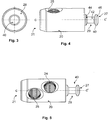
- Figure 1 shows a perspective view of a connector 1, in a decoupled state.
- the connector 1 comprises a first connecting part 10 and a second connecting part 20 that are configured to be mechanically coupled together.
- the connector 1 is a split connector whose body is formed by connecting two halves that correspond to the first and second connecting parts 10, 20. This has the advantage that the connector 1 has a compact design and is easy to install.
- the principles of the present invention may also be applied to other types of mechanical connectors with bodies formed by more than two connecting parts.
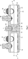
- the first and second connecting parts 10, 20 are preferably provided with an outer shape that is approximately cylindrical with respective central axes CC'. As shown in Fig. 2 , the respective central axes CC' become aligned when the first and second connecting parts 10, 20 are joined together in the coupling state, resulting in a connector body with an approximate cylindrical shape along the longitudinal axis AA'.
- a rear end 11 of the first connecting part 10 is provided with a blind hole 12 for receiving the extremity of a first electrical cable (not shown).
- the electrical cable can be fixed in the blind hole 12 by means of one or more clamping bolts 30, 32 that are tightened in threaded though-holes 14, 15 provided on an upper side of the first connecting part 10.
- the bolts 30, 32 clamp the electrical cable to the first connecting part 10 by pressing the cable against an inner side of the blind hole 12.
- the inner side of blind hole 12 may be provided with a structured surface 16 against which the electrical cable is pressed when the threaded bolts 30, 32 are tightened. As shown in Fig.
- the structured surface 16 extends over a strip area along the length of the blind hole 12, on a side opposed to the side where the threaded through-holes 14, 15 are located.
- the structured surface 16 increases the friction between the electrical cable and the inner side of the blind hole 12, so that the electrical cable can be efficiently secured by applying less tightening torque to the bolts 30, 32. This helps to reduce or avoid damage to the threads of the through-holes 14, 15 by using less tightening torque.
- the second connecting part 20 may also be provided, at its rear end 21, with a blind hole 22 for receiving the extremity of a second electrical cable (not shown).
- the second connecting part 20 may also be provided with threaded through-holes 24, 25 located in an upper side for receiving respective clamping bolts 36, 38.
- the clamping bolts 36, 38 are tightened in the through-holes 24, 25 against the cable inside the blind hole 22 to secure it into place.
- the blind hole 22 may also be provided with a structured surface 26 for improving the fixation of the second electrical cable.
- the structured surface 26 is preferably provided along the longitudinal length of the blind hole 22 and on an area of the blind hole opposed to the threaded through-holes 24, 25.
- the structured surfaces 16 and 26 may extend over different areas or over the whole surface of the inner side of the blind holes 12, 22, depending on the application.
- the structured surfaces 16, 26 may also be divided into more than one structured areas.
- the second connecting part 20 is provided with a coupling element 40 that is inserted in a coupling cavity 50 provided on the first connecting part 10.
- the coupling element 40 and the cavity 50 are respectively provided at respective front-ends 17, 27 of the first and second connecting parts 10, 20, opposite to the respective rear ends 11, 21.
- the coupling element 40 may be provided with a circular profile that allows a free rotation between the first and second connecting parts 10, 20 so that the first and second connecting parts 10, 20 can be clamped in any rotation position.
- the coupling element 40 is preferably provided as a protrusion 40 formed on the front-end 27 of the second connecting part 20 and which protrudes outwards along the central axis CC'.
- the protrusion 40 is preferably provided at the center of the front-end side 27, aligned with the central axis CC'.
- the protrusion 40 has preferably a shape with cylindrical symmetry about the central axis CC' so that it can be inserted inside the coupling cavity 50 with any orientation and be freely rotated by 360° about the longitudinal axis AA'.
- the coupling cavity 50 is also provided with an inner profile that allows the free rotation of the coupling element 40.
- the coupling cavity 50 is provided at the front side 17 of the first connecting part 10 with a frontal opening 52 adapted to receive the coupling element 40 when the second coupling part 20 abuts with the first connecting part 10 along a front-end to front-end direction, i.e. along the axis direction CC'.
- the cavity 50 is provided with an additional, lateral opening 54 located on a lateral side of the first connecting part 10 and that allows insertion of the coupling element 40 into the coupling cavity 50 by approaching the first and second connecting parts 10, 20 laterally, i.e.
- the lateral opening 54 preferably runs from the frontal opening 52 to the bottom of the cavity 50 for facilitating insertion of the coupling element 40 from the lateral side of the first connecting part 10.
- the cavity 50 is provided with a single lateral opening, so that the coupling element 40 may be inserted from only one lateral side of the connector body.
- the cavity 50 is provided with more than one lateral opening for allowing lateral insertion of the coupling element 40 from several lateral sides of the connector 1.
- the first and second coupling parts 10, 20 are fixed together in the coupling state shown in Fig. 2 by means of a coupling bolt 34 that is tightened through a threaded through-hole located on above the coupling cavity 50 by a tightening torque T so as to clamp the coupling element 40 against a opposed side of the cavity 50.
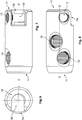
- the through-hole 13 can be provided on the upper side of the first connecting part 10 with an angular displacement with respect to the nearest through-hole 15.
- an angular displacement of 30° can be used.
- the other threaded through-holes provided on the upper side of the first and second connecting parts 10, 20 may also be provided with a non-zero angular displacement with respect to each other, instead of being aligned in a same direction, so as to facilitate tightening of the respective bolts. Consequently, since the use of an angular displacement among the threaded through-holes allows locating the bolts closer to each other, and therefore, the size of the connector 1 can be further reduced even if large bolts have to be used.
- Fig. 9 shows the angular displacement between the bolts arranged on the respective through holes located on the upper sides of the first and second connecting parts 10, 20.
- an electrical contact element 28 may be provided on the front-end 27 of the second connecting part 20.
- the electrical contact element 28 may be provided as a flat surface, such as a disc, located on the front side 27 of the second connecting part 10 so as to touch a border 18 of the front side 17 of the first connecting part 10 when the two connecting parts 10, 20 are joined together.
- the electrical contact element 28 may be provided by the contact surface of the front-side 27 of the second connecting part 20 or may be provided as an additional material having good electrical properties.
- the electrical coupling may be further improved by providing a corresponding electrical contact element (not shown) on the border 18 of the first connecting part 10.
- the connector 1 By establishing the electrical coupling between the first and second connecting parts 10, 20 via electrical contact element(s) as described above, the electrical contact is no longer done by the mechanical coupling element 40 but by the larger flat surface of the electrical contact element itself. Thus, the connector 1 exhibits a good electrical contact behavior.
- the stability of the mechanical and/or electrical coupling of the connector 1 can be further improved by providing the coupling cavity 50 and the coupling bolt 34 with profiles that match, at least partially, with the outer profile of the coupling element 40.
- the protrusion 40 may be shaped with a circular, dove tail profile that can be generally described as being formed by an inner region 42 of a cylindrical shape topped by two conical shapes 44, 46 at opposed sides.
- the circular, dove tail profile results in an annular groove 29 of inclined edges that runs around the perimeter of the protrusion 40.
- the annular groove 29 allows contact with the coupling bolt 34, irrespectively from the orientation of the coupling element 40 inside the cavity 50.
- the coupling bolt 34 may be provided with a tip 36 having a conical shape with a flat base and inclined edges that closely match the inclined edges profile of the annular groove 29 at the area of contact between the tip 36 and the coupling element 40.
- the coupling bolt 34 when the coupling bolt 34 is tightened against the coupling element 40 located inside the cavity 50, the force applied by the inclined edges of the tip 36 conical shape against the inclined edges of the groove 29 forces the coupling element 40 to move towards the bottom of the cavity 50, thereby bringing the first and second connecting parts 10, 20 together and efficiently securing the protrusion 40 inside the cavity 50.
- the electrical contact element 27 is also forced against the border 18 at the front edge of the first connecting part 10 when the coupling bolt 34 is tightened, a good and stable electrical coupling between the first and second connecting parts 10, 20 can be ensured.
- the slopes of the conical shapes defining the dove tail profile of the coupling element 40 and the conical shape of the tip 36 are preferably selected to match each other. For instance, an inclination of the dove tail of 30° with respect to a direction orthogonal to the central axis CC' may be used. However, a dovetail profile in which the overture angle of the conical shape(s) 44, 46, i.e. the angle between the inclined surface of the conical shapes 44, 46 with respect to the horizontal direction CC', is within a range from 20° to 85° may be advantageously used.
- the mechanical alignment between the coupling element 40 and the cavity 50 can be further improved by providing one or more recesses 56 in a bottom side of the cavity 50 for receiving the edges of the dove tail profile.
- the tightening of the coupling bolt 34 forces the edges of the dove tail profile to enter into the recesses 56, thereby, locking the coupling element 40 into the coupling position.
- the recesses 56 are not provided along the entire inner perimeter of the cavity 50 so as to permit that the coupling element 40 be inserted into the cavity 50 from the front end 17 as well as to facilitate the insertion from the lateral side of the first connecting part 10.
- the coupling element 40 is then pressed against the recesses 56 under the contact pressure exerted by the coupling bolt 34. Accordingly, a connector 1 of increased mechanical and electrical stability can be provided.
- the principles of the present invention can also be advantageously applied to any mechanical connector and/or for other applications.
- the concept described above of a coupling bolt with a tip having a conical shape profile that substantially matches the shape profile of the coupling element of the second connecting part may be advantageously applied to a connector in which the coupling cavity that receives the coupling element is not provided with a lateral opening for receiving the coupling element from a side-to-side direction, for e.g. to connectors designed for coupling the two halves of the connector body along a front-end to front-end direction or with a given angle.
- connector 10 first connecting part 11 rear end 12 blind hole 13, 14, 15 threaded through-holes 16 structured surface of blind hole 17 front-end 18 border 20 second connecting part 21 rear end 22 blind hole 24, 25 threaded through-holes 26 structured surface 27 front-end 29 annular groove 28 electrical contact element 30, 32, 36, 38 bolts 34 coupling bolt 36 tip of coupling bolt 40 coupling element, protrusion 42 inner region of protrusion 44, 46 conical shapes AA' longitudinal axis CC' central axis of connecting parts 50 cavity 52 frontal opening of cavity 54 lateral opening of cavity 56 recess T torque direction
Landscapes
- Details Of Connecting Devices For Male And Female Coupling (AREA)
- Connections By Means Of Piercing Elements, Nuts, Or Screws (AREA)
Priority Applications (5)
| Application Number | Priority Date | Filing Date | Title |
|---|---|---|---|
| EP15306691.5A EP3159977B1 (fr) | 2015-10-21 | 2015-10-21 | Connecteur partagé avec queue d'aronde circulaire |
| AU2016247049A AU2016247049B2 (en) | 2015-10-21 | 2016-10-18 | Split connector with circular dove tail |
| CN202111060071.7A CN113922107A (zh) | 2015-10-21 | 2016-10-21 | 具有圆楔榫的分立式连接器 |
| US15/331,122 US10135158B2 (en) | 2015-10-21 | 2016-10-21 | Split connector with circular dove tail |
| CN201610920576.9A CN107017473A (zh) | 2015-10-21 | 2016-10-21 | 具有圆楔榫的分立式连接器 |
Applications Claiming Priority (1)
| Application Number | Priority Date | Filing Date | Title |
|---|---|---|---|
| EP15306691.5A EP3159977B1 (fr) | 2015-10-21 | 2015-10-21 | Connecteur partagé avec queue d'aronde circulaire |
Publications (2)
| Publication Number | Publication Date |
|---|---|
| EP3159977A1 true EP3159977A1 (fr) | 2017-04-26 |
| EP3159977B1 EP3159977B1 (fr) | 2019-08-28 |
Family
ID=54360396
Family Applications (1)
| Application Number | Title | Priority Date | Filing Date |
|---|---|---|---|
| EP15306691.5A Active EP3159977B1 (fr) | 2015-10-21 | 2015-10-21 | Connecteur partagé avec queue d'aronde circulaire |
Country Status (4)
| Country | Link |
|---|---|
| US (1) | US10135158B2 (fr) |
| EP (1) | EP3159977B1 (fr) |
| CN (2) | CN107017473A (fr) |
| AU (1) | AU2016247049B2 (fr) |
Cited By (1)
| Publication number | Priority date | Publication date | Assignee | Title |
|---|---|---|---|---|
| EP3457496A1 (fr) * | 2017-09-15 | 2019-03-20 | Tyco Electronics-Simel | Connecteur électrique |
Families Citing this family (9)
| Publication number | Priority date | Publication date | Assignee | Title |
|---|---|---|---|---|
| USD847091S1 (en) * | 2016-11-11 | 2019-04-30 | Afl Ig Llc | Housing for cable transition assembly |
| CN107732520A (zh) * | 2017-11-23 | 2018-02-23 | 国网上海市电力公司 | 一种配置电缆端子型快速接头 |
| JP7064605B2 (ja) | 2018-03-29 | 2022-05-10 | モレックス エルエルシー | ケーブルハーネスを保護及び支持するためのスパイン |
| USD865692S1 (en) * | 2018-03-29 | 2019-11-05 | Molex, Llc | Cable harness with protective casing |
| DE102018003443B4 (de) * | 2018-04-27 | 2019-12-05 | Gentherm Gmbh | Vorrichtung zum Herstellen einer elektrisch leitfähigen Verbindung |
| CN108963699A (zh) * | 2018-07-02 | 2018-12-07 | 太仓市友达电气技术有限公司 | 一种万向接线头 |
| US11183782B2 (en) * | 2019-03-13 | 2021-11-23 | Hubbell Incorporated | Adjustable neutral bars and adjustable neutral bar assemblies |
| US11069990B2 (en) * | 2019-03-15 | 2021-07-20 | Hubbell Incorporated | Pin adapter type cable connectors |
| CN110635263A (zh) * | 2019-08-23 | 2019-12-31 | 东莞市鼎通精密五金股份有限公司 | 一种连接器组件及其防误脱插头 |
Citations (5)
| Publication number | Priority date | Publication date | Assignee | Title |
|---|---|---|---|---|
| GB2319402A (en) * | 1996-11-08 | 1998-05-20 | B & H Ltd | Two-part connector to join conductors |
| EP1280239A2 (fr) * | 2001-07-25 | 2003-01-29 | Sicame Electrical Developments Ltd | Connecteur |
| EP1914837A2 (fr) * | 2006-10-20 | 2008-04-23 | Tyco Electronics UK Ltd. | Connecteur électrique |
| US20130295790A1 (en) * | 2012-05-02 | 2013-11-07 | Tyco Electronics Corporation | Connector assemblies and systems and methods for forming disconnectable joint assemblies |
| WO2014079558A1 (fr) | 2012-11-21 | 2014-05-30 | Pfisterer Kontaktsysteme Gmbh | Dispositif pour le raccordement ou l'assemblage électrique d'au moins un conducteur d'un câble d'alimentation en énergie |
Family Cites Families (36)
| Publication number | Priority date | Publication date | Assignee | Title |
|---|---|---|---|---|
| US2713154A (en) * | 1954-06-18 | 1955-07-12 | Patton Macguyer Co | Electrical connector |
| US3727171A (en) * | 1971-07-23 | 1973-04-10 | Westinghouse Canada Ltd | Bus connector assembly |
| US4053202A (en) * | 1976-04-27 | 1977-10-11 | Norden Alexander | Lay-in connectors |
| US4458976A (en) * | 1982-10-14 | 1984-07-10 | The United States Of America As Represented By The Secretary Of The Navy | Terminal and connector assembly for electrical cables |
| US4568138A (en) * | 1984-11-08 | 1986-02-04 | Mckenzie Thomas J | Electrical wire connector |
| US5000705A (en) * | 1990-03-08 | 1991-03-19 | Amp Incorporated | Electrical cable connection device |
| US5199905A (en) * | 1992-03-09 | 1993-04-06 | Connector Manufacturing Co. | Lay-in pedestal connector bar and method |
| DE4430406A1 (de) * | 1994-08-26 | 1996-02-29 | Arcus Elektrotech | Schraubverbinder für Kabel, insbesondere für Mittelspannungs-Verbindungsmuffen |
| US5727314A (en) * | 1996-02-15 | 1998-03-17 | Erico International Corporation | Method of making an insulated set screw electrical connector |
| US5912433A (en) * | 1997-01-17 | 1999-06-15 | Minnesota Mining And Manufacturing Company | Cable closure injection sealed with low surface energy adhesive |
| US5876224A (en) * | 1997-04-24 | 1999-03-02 | Framatome Connectors Usa Inc. | Bus bar adaptor |
| US6338658B1 (en) * | 2000-02-14 | 2002-01-15 | Ilsco Corporation | Slotted electrical connector |
| GB0202710D0 (en) * | 2002-02-06 | 2002-03-20 | Tyco Electronics Ltd Uk | Fastener |
| US6909049B2 (en) * | 2002-05-03 | 2005-06-21 | Fci Americas Technologies, Inc. | Electrical connector for angled conductors |
| GB0227901D0 (en) * | 2002-11-29 | 2003-01-08 | Tyco Electronics Ltd Uk | Electrical one-piece double-ended receptacle contact and electrical connector comprising such a contact |
| US7044776B2 (en) * | 2003-12-02 | 2006-05-16 | King Jr Lloyd Herbert | Wire connector |
| US7320626B2 (en) * | 2004-06-29 | 2008-01-22 | Thomas & Betts International, Inc. | Transformer stud connector with improved conductivity using a special thread profile |
| US7056163B2 (en) * | 2004-09-20 | 2006-06-06 | Connector Manufacturing Company | Neutral bar with slide-on saddle lug |
| FR2876755B1 (fr) * | 2004-10-20 | 2007-01-26 | Pcm Pompes Sa | Dispositif de pompage a pompe a cavites progressives |
| FR2907859B1 (fr) * | 2006-10-30 | 2008-12-19 | Tyco Electronics Simel Soc Par | Ensemble a vis a rupture programmee |
| DE202007009351U1 (de) * | 2007-07-04 | 2007-09-06 | Lapp Engineering & Co. | Steckverbinder mit Schraubanschluss |
| US7896714B2 (en) * | 2008-06-13 | 2011-03-01 | Hubbell Incorporated | Submersible electrical set-screw connector |
| US7537467B1 (en) * | 2008-10-07 | 2009-05-26 | Arlington Industries, Inc. | Grounding terminal block assembly for multiple services |
| US7931508B1 (en) * | 2009-02-19 | 2011-04-26 | Carr James E | Multi-fit transformer stud mounting and methods of making the same |
| EP2226899B1 (fr) * | 2009-02-25 | 2011-05-18 | Nexans | Dispositif de liaison de deux conducteurs électriques |
| IT1398147B1 (it) * | 2009-07-08 | 2013-02-14 | Pini | Morsetto per connessioni elettriche |
| US8425264B2 (en) * | 2010-09-16 | 2013-04-23 | Pan Electric Corporation | Electrical connector |
| JP5758178B2 (ja) * | 2011-04-12 | 2015-08-05 | 富士機械製造株式会社 | 撮像装置 |
| US8277263B1 (en) * | 2011-06-09 | 2012-10-02 | Bridgeport Fittings, Inc. | Intersystem grounding bridge |
| CN202344315U (zh) * | 2011-11-22 | 2012-07-25 | 财团法人精密机械研究发展中心 | 具电力传输的刀轴与刀把结构 |
| WO2013078169A2 (fr) * | 2011-11-23 | 2013-05-30 | 3M Innovative Properties Company | Connecteur électrique |
| DE102012013176A1 (de) * | 2012-06-29 | 2014-01-02 | Pfisterer Kontaktsysteme Gmbh | Abreißschraube, zugehöriges System sowie Vorrichtung zum Schraubklemmen elektrischer Leiter mit einer solchen Abreißschraube |
| CN202811084U (zh) * | 2012-09-11 | 2013-03-20 | 安徽全柴动力股份有限公司 | 一种拉线销调速机构 |
| CN203119106U (zh) * | 2013-03-07 | 2013-08-07 | 宁夏电力公司吴忠供电局 | 接线盒线路连接器 |
| CN103682697A (zh) * | 2013-04-22 | 2014-03-26 | 上海永固电力器材有限公司 | 螺栓型铝端子 |
| DE202013010921U1 (de) * | 2013-11-27 | 2015-03-02 | Scherdel Innotec Forschungs- Und Entwicklungs-Gmbh | Batteriepolklemmen-Spannvorrichtung sowie Batteriepolklemme damit |
-
2015
- 2015-10-21 EP EP15306691.5A patent/EP3159977B1/fr active Active
-
2016
- 2016-10-18 AU AU2016247049A patent/AU2016247049B2/en active Active
- 2016-10-21 CN CN201610920576.9A patent/CN107017473A/zh active Pending
- 2016-10-21 CN CN202111060071.7A patent/CN113922107A/zh active Pending
- 2016-10-21 US US15/331,122 patent/US10135158B2/en active Active
Patent Citations (5)
| Publication number | Priority date | Publication date | Assignee | Title |
|---|---|---|---|---|
| GB2319402A (en) * | 1996-11-08 | 1998-05-20 | B & H Ltd | Two-part connector to join conductors |
| EP1280239A2 (fr) * | 2001-07-25 | 2003-01-29 | Sicame Electrical Developments Ltd | Connecteur |
| EP1914837A2 (fr) * | 2006-10-20 | 2008-04-23 | Tyco Electronics UK Ltd. | Connecteur électrique |
| US20130295790A1 (en) * | 2012-05-02 | 2013-11-07 | Tyco Electronics Corporation | Connector assemblies and systems and methods for forming disconnectable joint assemblies |
| WO2014079558A1 (fr) | 2012-11-21 | 2014-05-30 | Pfisterer Kontaktsysteme Gmbh | Dispositif pour le raccordement ou l'assemblage électrique d'au moins un conducteur d'un câble d'alimentation en énergie |
Cited By (1)
| Publication number | Priority date | Publication date | Assignee | Title |
|---|---|---|---|---|
| EP3457496A1 (fr) * | 2017-09-15 | 2019-03-20 | Tyco Electronics-Simel | Connecteur électrique |
Also Published As
| Publication number | Publication date |
|---|---|
| EP3159977B1 (fr) | 2019-08-28 |
| US20170117644A1 (en) | 2017-04-27 |
| CN107017473A (zh) | 2017-08-04 |
| AU2016247049B2 (en) | 2021-08-12 |
| US10135158B2 (en) | 2018-11-20 |
| CN113922107A (zh) | 2022-01-11 |
| AU2016247049A1 (en) | 2017-05-04 |
Similar Documents
| Publication | Publication Date | Title |
|---|---|---|
| EP3159977A1 (fr) | Connecteur partagé avec queue d'aronde circulaire | |
| AU2008254918B2 (en) | Power utility connector with a plurality of conductor receiving channels | |
| KR101059295B1 (ko) | 동축 케이블 커넥터 및 너트 부재 | |
| CN111864473A (zh) | 电插接连接部的插接连接器以及由其形成的电插接连接部 | |
| US10218131B2 (en) | Right angle coaxial cable and connector assembly | |
| BR102013030899A2 (pt) | Conjunto de alinhamento elástico | |
| BRPI0814030B1 (pt) | Conjunto conector elétrico de derivação tipo cunha e sistema conector elétrico | |
| EP1157447B1 (fr) | Connecteur electrique a piece deformable | |
| HUE030262T2 (en) | Swaged connectors for a grounding grid | |
| BRPI0617038A2 (pt) | conjunto conector elétrico | |
| GB2262396A (en) | Connector for elongate objects | |
| AU671173B2 (en) | Electrical connector | |
| US20170125781A1 (en) | Battery terminal and method of assembling it | |
| GB2319402A (en) | Two-part connector to join conductors | |
| JP3234720U (ja) | 手工具の枢着構造 | |
| CA2334187C (fr) | Connecteur mecanique plat avec vis interieure | |
| CN210739046U (zh) | 外直接组件 | |
| JP4167947B2 (ja) | ローパーテーションの連結装置 | |
| CN222614169U (zh) | 一种组合式销钉连接接头 | |
| US3803536A (en) | Clamp connector | |
| CN220281138U (zh) | 线缆夹紧结构及充电枪 | |
| US20250158325A1 (en) | Split Parallel Connector | |
| US20260094982A1 (en) | Rotating Wedge Connectors | |
| BR102024012221A2 (pt) | Conector mecânico para conectar um cabo elétrico | |
| EP3457496B1 (fr) | Connecteur électrique |
Legal Events
| Date | Code | Title | Description |
|---|---|---|---|
| PUAI | Public reference made under article 153(3) epc to a published international application that has entered the european phase |
Free format text: ORIGINAL CODE: 0009012 |
|
| STAA | Information on the status of an ep patent application or granted ep patent |
Free format text: STATUS: THE APPLICATION HAS BEEN PUBLISHED |
|
| AK | Designated contracting states |
Kind code of ref document: A1 Designated state(s): AL AT BE BG CH CY CZ DE DK EE ES FI FR GB GR HR HU IE IS IT LI LT LU LV MC MK MT NL NO PL PT RO RS SE SI SK SM TR |
|
| AX | Request for extension of the european patent |
Extension state: BA ME |
|
| STAA | Information on the status of an ep patent application or granted ep patent |
Free format text: STATUS: REQUEST FOR EXAMINATION WAS MADE |
|
| STAA | Information on the status of an ep patent application or granted ep patent |
Free format text: STATUS: EXAMINATION IS IN PROGRESS |
|
| 17P | Request for examination filed |
Effective date: 20171024 |
|
| RBV | Designated contracting states (corrected) |
Designated state(s): AL AT BE BG CH CY CZ DE DK EE ES FI FR GB GR HR HU IE IS IT LI LT LU LV MC MK MT NL NO PL PT RO RS SE SI SK SM TR |
|
| 17Q | First examination report despatched |
Effective date: 20171204 |
|
| RAP1 | Party data changed (applicant data changed or rights of an application transferred) |
Owner name: TYCO ELECTRONICS SIMEL Owner name: TYCO ELECTRONICS UK LTD. |
|
| GRAP | Despatch of communication of intention to grant a patent |
Free format text: ORIGINAL CODE: EPIDOSNIGR1 |
|
| STAA | Information on the status of an ep patent application or granted ep patent |
Free format text: STATUS: GRANT OF PATENT IS INTENDED |
|
| RIC1 | Information provided on ipc code assigned before grant |
Ipc: H01R 4/00 20060101ALN20190301BHEP Ipc: H01R 4/36 20060101ALI20190301BHEP Ipc: H01R 13/621 20060101ALN20190301BHEP Ipc: H01R 13/631 20060101ALI20190301BHEP Ipc: H01R 11/11 20060101ALI20190301BHEP Ipc: H01R 11/26 20060101AFI20190301BHEP Ipc: H01R 13/213 20060101ALN20190301BHEP |
|
| INTG | Intention to grant announced |
Effective date: 20190325 |
|
| GRAS | Grant fee paid |
Free format text: ORIGINAL CODE: EPIDOSNIGR3 |
|
| GRAA | (expected) grant |
Free format text: ORIGINAL CODE: 0009210 |
|
| STAA | Information on the status of an ep patent application or granted ep patent |
Free format text: STATUS: THE PATENT HAS BEEN GRANTED |
|
| AK | Designated contracting states |
Kind code of ref document: B1 Designated state(s): AL AT BE BG CH CY CZ DE DK EE ES FI FR GB GR HR HU IE IS IT LI LT LU LV MC MK MT NL NO PL PT RO RS SE SI SK SM TR |
|
| REG | Reference to a national code |
Ref country code: GB Ref legal event code: FG4D |
|
| REG | Reference to a national code |
Ref country code: CH Ref legal event code: EP |
|
| REG | Reference to a national code |
Ref country code: AT Ref legal event code: REF Ref document number: 1173564 Country of ref document: AT Kind code of ref document: T Effective date: 20190915 |
|
| REG | Reference to a national code |
Ref country code: IE Ref legal event code: FG4D |
|
| REG | Reference to a national code |
Ref country code: DE Ref legal event code: R096 Ref document number: 602015036633 Country of ref document: DE |
|
| REG | Reference to a national code |
Ref country code: NL Ref legal event code: MP Effective date: 20190828 |
|
| REG | Reference to a national code |
Ref country code: LT Ref legal event code: MG4D |
|
| PG25 | Lapsed in a contracting state [announced via postgrant information from national office to epo] |
Ref country code: NL Free format text: LAPSE BECAUSE OF FAILURE TO SUBMIT A TRANSLATION OF THE DESCRIPTION OR TO PAY THE FEE WITHIN THE PRESCRIBED TIME-LIMIT Effective date: 20190828 Ref country code: SE Free format text: LAPSE BECAUSE OF FAILURE TO SUBMIT A TRANSLATION OF THE DESCRIPTION OR TO PAY THE FEE WITHIN THE PRESCRIBED TIME-LIMIT Effective date: 20190828 Ref country code: BG Free format text: LAPSE BECAUSE OF FAILURE TO SUBMIT A TRANSLATION OF THE DESCRIPTION OR TO PAY THE FEE WITHIN THE PRESCRIBED TIME-LIMIT Effective date: 20191128 Ref country code: NO Free format text: LAPSE BECAUSE OF FAILURE TO SUBMIT A TRANSLATION OF THE DESCRIPTION OR TO PAY THE FEE WITHIN THE PRESCRIBED TIME-LIMIT Effective date: 20191128 Ref country code: LT Free format text: LAPSE BECAUSE OF FAILURE TO SUBMIT A TRANSLATION OF THE DESCRIPTION OR TO PAY THE FEE WITHIN THE PRESCRIBED TIME-LIMIT Effective date: 20190828 Ref country code: PT Free format text: LAPSE BECAUSE OF FAILURE TO SUBMIT A TRANSLATION OF THE DESCRIPTION OR TO PAY THE FEE WITHIN THE PRESCRIBED TIME-LIMIT Effective date: 20191230 Ref country code: FI Free format text: LAPSE BECAUSE OF FAILURE TO SUBMIT A TRANSLATION OF THE DESCRIPTION OR TO PAY THE FEE WITHIN THE PRESCRIBED TIME-LIMIT Effective date: 20190828 Ref country code: HR Free format text: LAPSE BECAUSE OF FAILURE TO SUBMIT A TRANSLATION OF THE DESCRIPTION OR TO PAY THE FEE WITHIN THE PRESCRIBED TIME-LIMIT Effective date: 20190828 |
|
| PG25 | Lapsed in a contracting state [announced via postgrant information from national office to epo] |
Ref country code: LV Free format text: LAPSE BECAUSE OF FAILURE TO SUBMIT A TRANSLATION OF THE DESCRIPTION OR TO PAY THE FEE WITHIN THE PRESCRIBED TIME-LIMIT Effective date: 20190828 Ref country code: AL Free format text: LAPSE BECAUSE OF FAILURE TO SUBMIT A TRANSLATION OF THE DESCRIPTION OR TO PAY THE FEE WITHIN THE PRESCRIBED TIME-LIMIT Effective date: 20190828 Ref country code: IS Free format text: LAPSE BECAUSE OF FAILURE TO SUBMIT A TRANSLATION OF THE DESCRIPTION OR TO PAY THE FEE WITHIN THE PRESCRIBED TIME-LIMIT Effective date: 20191228 Ref country code: RS Free format text: LAPSE BECAUSE OF FAILURE TO SUBMIT A TRANSLATION OF THE DESCRIPTION OR TO PAY THE FEE WITHIN THE PRESCRIBED TIME-LIMIT Effective date: 20190828 Ref country code: GR Free format text: LAPSE BECAUSE OF FAILURE TO SUBMIT A TRANSLATION OF THE DESCRIPTION OR TO PAY THE FEE WITHIN THE PRESCRIBED TIME-LIMIT Effective date: 20191129 Ref country code: ES Free format text: LAPSE BECAUSE OF FAILURE TO SUBMIT A TRANSLATION OF THE DESCRIPTION OR TO PAY THE FEE WITHIN THE PRESCRIBED TIME-LIMIT Effective date: 20190828 |
|
| REG | Reference to a national code |
Ref country code: AT Ref legal event code: MK05 Ref document number: 1173564 Country of ref document: AT Kind code of ref document: T Effective date: 20190828 |
|
| PG25 | Lapsed in a contracting state [announced via postgrant information from national office to epo] |
Ref country code: TR Free format text: LAPSE BECAUSE OF FAILURE TO SUBMIT A TRANSLATION OF THE DESCRIPTION OR TO PAY THE FEE WITHIN THE PRESCRIBED TIME-LIMIT Effective date: 20190828 |
|
| PG25 | Lapsed in a contracting state [announced via postgrant information from national office to epo] |
Ref country code: AT Free format text: LAPSE BECAUSE OF FAILURE TO SUBMIT A TRANSLATION OF THE DESCRIPTION OR TO PAY THE FEE WITHIN THE PRESCRIBED TIME-LIMIT Effective date: 20190828 Ref country code: DK Free format text: LAPSE BECAUSE OF FAILURE TO SUBMIT A TRANSLATION OF THE DESCRIPTION OR TO PAY THE FEE WITHIN THE PRESCRIBED TIME-LIMIT Effective date: 20190828 Ref country code: IT Free format text: LAPSE BECAUSE OF FAILURE TO SUBMIT A TRANSLATION OF THE DESCRIPTION OR TO PAY THE FEE WITHIN THE PRESCRIBED TIME-LIMIT Effective date: 20190828 Ref country code: EE Free format text: LAPSE BECAUSE OF FAILURE TO SUBMIT A TRANSLATION OF THE DESCRIPTION OR TO PAY THE FEE WITHIN THE PRESCRIBED TIME-LIMIT Effective date: 20190828 Ref country code: PL Free format text: LAPSE BECAUSE OF FAILURE TO SUBMIT A TRANSLATION OF THE DESCRIPTION OR TO PAY THE FEE WITHIN THE PRESCRIBED TIME-LIMIT Effective date: 20190828 Ref country code: RO Free format text: LAPSE BECAUSE OF FAILURE TO SUBMIT A TRANSLATION OF THE DESCRIPTION OR TO PAY THE FEE WITHIN THE PRESCRIBED TIME-LIMIT Effective date: 20190828 |
|
| PG25 | Lapsed in a contracting state [announced via postgrant information from national office to epo] |
Ref country code: IS Free format text: LAPSE BECAUSE OF FAILURE TO SUBMIT A TRANSLATION OF THE DESCRIPTION OR TO PAY THE FEE WITHIN THE PRESCRIBED TIME-LIMIT Effective date: 20200224 Ref country code: MC Free format text: LAPSE BECAUSE OF FAILURE TO SUBMIT A TRANSLATION OF THE DESCRIPTION OR TO PAY THE FEE WITHIN THE PRESCRIBED TIME-LIMIT Effective date: 20190828 Ref country code: CZ Free format text: LAPSE BECAUSE OF FAILURE TO SUBMIT A TRANSLATION OF THE DESCRIPTION OR TO PAY THE FEE WITHIN THE PRESCRIBED TIME-LIMIT Effective date: 20190828 Ref country code: SK Free format text: LAPSE BECAUSE OF FAILURE TO SUBMIT A TRANSLATION OF THE DESCRIPTION OR TO PAY THE FEE WITHIN THE PRESCRIBED TIME-LIMIT Effective date: 20190828 Ref country code: SM Free format text: LAPSE BECAUSE OF FAILURE TO SUBMIT A TRANSLATION OF THE DESCRIPTION OR TO PAY THE FEE WITHIN THE PRESCRIBED TIME-LIMIT Effective date: 20190828 |
|
| REG | Reference to a national code |
Ref country code: CH Ref legal event code: PL |
|
| REG | Reference to a national code |
Ref country code: DE Ref legal event code: R097 Ref document number: 602015036633 Country of ref document: DE |
|
| PLBE | No opposition filed within time limit |
Free format text: ORIGINAL CODE: 0009261 |
|
| STAA | Information on the status of an ep patent application or granted ep patent |
Free format text: STATUS: NO OPPOSITION FILED WITHIN TIME LIMIT |
|
| PG2D | Information on lapse in contracting state deleted |
Ref country code: IS |
|
| PG25 | Lapsed in a contracting state [announced via postgrant information from national office to epo] |
Ref country code: LU Free format text: LAPSE BECAUSE OF NON-PAYMENT OF DUE FEES Effective date: 20191021 Ref country code: CH Free format text: LAPSE BECAUSE OF NON-PAYMENT OF DUE FEES Effective date: 20191031 Ref country code: LI Free format text: LAPSE BECAUSE OF NON-PAYMENT OF DUE FEES Effective date: 20191031 |
|
| 26N | No opposition filed |
Effective date: 20200603 |
|
| REG | Reference to a national code |
Ref country code: BE Ref legal event code: MM Effective date: 20191031 |
|
| PG25 | Lapsed in a contracting state [announced via postgrant information from national office to epo] |
Ref country code: BE Free format text: LAPSE BECAUSE OF NON-PAYMENT OF DUE FEES Effective date: 20191031 Ref country code: SI Free format text: LAPSE BECAUSE OF FAILURE TO SUBMIT A TRANSLATION OF THE DESCRIPTION OR TO PAY THE FEE WITHIN THE PRESCRIBED TIME-LIMIT Effective date: 20190828 |
|
| PG25 | Lapsed in a contracting state [announced via postgrant information from national office to epo] |
Ref country code: IE Free format text: LAPSE BECAUSE OF NON-PAYMENT OF DUE FEES Effective date: 20191021 |
|
| PG25 | Lapsed in a contracting state [announced via postgrant information from national office to epo] |
Ref country code: CY Free format text: LAPSE BECAUSE OF FAILURE TO SUBMIT A TRANSLATION OF THE DESCRIPTION OR TO PAY THE FEE WITHIN THE PRESCRIBED TIME-LIMIT Effective date: 20190828 |
|
| PG25 | Lapsed in a contracting state [announced via postgrant information from national office to epo] |
Ref country code: MT Free format text: LAPSE BECAUSE OF FAILURE TO SUBMIT A TRANSLATION OF THE DESCRIPTION OR TO PAY THE FEE WITHIN THE PRESCRIBED TIME-LIMIT Effective date: 20190828 Ref country code: HU Free format text: LAPSE BECAUSE OF FAILURE TO SUBMIT A TRANSLATION OF THE DESCRIPTION OR TO PAY THE FEE WITHIN THE PRESCRIBED TIME-LIMIT; INVALID AB INITIO Effective date: 20151021 |
|
| PG25 | Lapsed in a contracting state [announced via postgrant information from national office to epo] |
Ref country code: MK Free format text: LAPSE BECAUSE OF FAILURE TO SUBMIT A TRANSLATION OF THE DESCRIPTION OR TO PAY THE FEE WITHIN THE PRESCRIBED TIME-LIMIT Effective date: 20190828 |
|
| PGFP | Annual fee paid to national office [announced via postgrant information from national office to epo] |
Ref country code: GB Payment date: 20250904 Year of fee payment: 11 |
|
| PGFP | Annual fee paid to national office [announced via postgrant information from national office to epo] |
Ref country code: FR Payment date: 20250908 Year of fee payment: 11 |
|
| PGFP | Annual fee paid to national office [announced via postgrant information from national office to epo] |
Ref country code: DE Payment date: 20250902 Year of fee payment: 11 |