EP3162973A1 - Anschlussvorrichtung für eine decke, die an einer bodenplatte abgehängt ist - Google Patents
Anschlussvorrichtung für eine decke, die an einer bodenplatte abgehängt ist Download PDFInfo
- Publication number
- EP3162973A1 EP3162973A1 EP16193373.4A EP16193373A EP3162973A1 EP 3162973 A1 EP3162973 A1 EP 3162973A1 EP 16193373 A EP16193373 A EP 16193373A EP 3162973 A1 EP3162973 A1 EP 3162973A1
- Authority
- EP
- European Patent Office
- Prior art keywords
- rod
- bracing
- slab
- elements
- edge
- Prior art date
- Legal status (The legal status is an assumption and is not a legal conclusion. Google has not performed a legal analysis and makes no representation as to the accuracy of the status listed.)
- Granted
Links
Images

Classifications
-
- E—FIXED CONSTRUCTIONS
- E04—BUILDING
- E04B—GENERAL BUILDING CONSTRUCTIONS; WALLS, e.g. PARTITIONS; ROOFS; FLOORS; CEILINGS; INSULATION OR OTHER PROTECTION OF BUILDINGS
- E04B9/00—Ceilings; Construction of ceilings, e.g. false ceilings; Ceiling construction with regard to insulation
- E04B9/18—Means for suspending the supporting construction
Definitions
- the present invention relates to a connecting device between a ceiling of a construction, generally consisting of a concrete slab, and a suspended structure, located in a plane parallel to the ceiling and at a distance from it.
- the device of the invention is intended for the field of construction, for making structures of the suspended ceiling or false ceiling type, comprising suspension lines which connect the ceiling slab, to a suspended structure, which may be composed for example of series of profiles. straight sections of various shapes: C, Omega, I, L, etc., on which are attached plates of insulation or plaster. This so-called false ceiling structure is suspended from the slab.
- the invention relates more particularly to the connecting device between the fixed slab and the suspended structure, called device hanger.
- suspension lines consist of metal rods, usually threaded rods, one end of which is fixed in the slab by means of an anchor, and the other end is fixed to the sections of the suspended structure thanks to a piece generally of complementary shape to the profile on which the hanger is fixed.
- the space between the ceiling tile and the suspended structure also called plenum, has a variable height.
- the rigidity of the suspension rods located in this space to connect the fixed ceiling tile to the suspended ceiling must be adapted to the dimensions of the false ceiling and especially to the distance separating it from the slab.
- Some known types of installation such as suspended medical devices, require the use of specific lines whose rigidity allows the suspended ceiling to support the weight of said devices.
- the lines then consist of profiles whose cross section is of the same order of magnitude as the sections constituting the suspended structure. In this way, the lines are extremely rigid, which makes it possible to suspend heavy medical devices.
- the invention proposes a lightweight hanger device, easy to manufacture, inexpensive, removable, having improved rigidity to prevent it from being deformed and for that its fixing to the slab is reliable, their rigidity also allowing to support relatively heavy equipment.
- bracing ensures the stability of the rod and prevent its deformation, opposing the reaction forces acting on the rod in a direction substantially parallel to the slab.
- the term "removably attached” means that the bracing means are adapted to be disassembled from the rod.
- the hanger is thus stiffened by the bracing means, which can be removed or added during the installation of the suspended ceiling, as desired.
- the bracing elements are in particular in the form of flanges or plates extending longitudinally and parallel to the rod of the hanger, one of the longitudinal edges is provided with a portion folded.
- the plates are diametrically opposed to each other.
- the bracing elements each comprise two free longitudinal edges (or ends), called the proximal edge and the distal edge with respect to the stem.
- the interlocking is such that the rotation around the rod of an element is blocked. This is called a self-locking system.
- each proximal edge of each brace member cooperates with the proximal edge of each of the other bracing members.
- the sleeve thus formed has a length (along the longitudinal axis of the rod) of at least 5 cm, preferably greater than 10 cm and even more preferably is greater than 15 cm. This length corresponds to the length of the bracing elements.
- each bracing element capable of being fitted with the edge of another bracing member comprises at least three folded folds successive fold lines, so as to form an angle of at least 30 ° (preferably 90 °) from one pan to the next, the three sections of a first element being complementary to the three sides of a second element to provide the sleeve.
- the width of a bracing member corresponds to the width of the last fold line away from the rod. This width corresponds the radius of the total surface in which the device is inscribed and on which the slab is intended to rest.
- Patents means planar portions of variable width constituting the different sides of the complementary ends of the planar elements.
- the bracing elements are identical to each other and comprise a terminal pan extending in a transverse dimension to the sleeve (or the rod) by their free end, preferably by forming a panel or a plate, of generally square or rectangular shape. .
- the bracing elements have the shape of a U and even more preferably, a branch is substantially longer than the others to result in a form of J.
- the complementary proximal edges of the bracing elements are able to fit freely between themselves and around the rod.
- the creases of the flanks of the complementary proximal edges of each bracing member, at a given angle, leaves a space of greater width than the diameter of the rod, allowing said ends to fit on the rod.
- the hanger device advantageously comprises four bracing elements whose complementary proximal edges, orthogonal sides, have a U-shape, seen in cross-section, and preferably, one of the branches of each U (pan terminal) forms the panel or plate mentioned above.
- the bracing elements are a metal part made of sheet steel, preferably protected against corrosion, advantageously by galvanizing.
- the bracing elements have a thickness greater than or equal to 15/10 mm, and a height of 20 cm, and fit on rods with a diameter of 6 mm.
- the device of the invention is composed of a threaded metal rod, over at least a part of its length, capable of being fixed by its upper end to the fixed slab, and by its lower end to the suspended structure, the rigid bracing elements, which form the bracing system of the rod, being arranged near its upper end, and being intended to be in contact with the slab and bear against the latter, said elements being by elsewhere immobilized on the rod by at least one nut engaged on the rod.
- the contact lines of the bracing elements with the slab form a bracing system, thus defining a surface capable of bearing against the ceiling tile, which makes it possible to stabilize the fixing of the rod in the slab and furthermore to stiffen the rod. .
- a bracing element thus forms, by the upper edge, a bearing surface, comprising a secondary portion associated with the sleeve and a main portion associated with the flange.
- the invention solves the problem of the propagation of air currents in the plenum between the slab and the suspended ceiling.
- the device comprising at least two hanger devices (each including a rod and its associated bracing elements), further includes at least one haze capable of being fixed to a respective bracing member of each hanger device, said veil then being in a plane orthogonal to the slab and parallel to the stem.
- this veil has a lower or preferably equal height, at the height of the plenum, and a length equal to the distance between two adjacent suspension lines, and is adapted to be fixed by one of its ends to a bracing element d a first hanger, and its opposite end to a bracing element of a second hanger.
- the veil recuts the volume of the plenum, which limits the flow of air, and therefore limits the spread of fire.
- the device comprises a web for each bracing member of a device of the invention.
- the sails are able to be arranged in the plenum orthogonal to the suspended ceiling, according to either parallel planes or diagonal planes.
- the overlapping sails of the volume of the plenum are plasterboard, cement or wood, preferably still plasterboard.
- FIG. 1 partially in perspective, is shown a concrete slab 5 to which is suspended a false ceiling structure 11, with the aid of suspension devices 1 and 1 'according to the invention, themselves attached to the slab 5 and the suspended ceiling structure 11.
- the false ceiling frame comprises parallel main beams called "primary" 7 and 7 'and smaller sized profiles fixed on the primary orthogonal.
- the hanger devices 1 and 1 ' are arranged at a distance from each other, being fixed respectively on the primary 7 and 7'.
- a panel or web 10, preferably plaster, is attached to the two hanger devices 1 and 1 'by two of its opposite ends 10A and 10B.
- the hanger device 1 is fixed to the slab 5 by means of an anchor 6 of known type, and to the primary 7 via a junction piece 9 of known type, of shape complementary to said profile.
- the hanger 1 device comprises a rod 2, preferably threaded over its entire length, four substantially planar and rigid elements 3A to 3D (only 3A, 3C and 3D appear on the figure 1 ), preferably sheet steel, removably attached to said rod, and at least one nut 8 for retaining the planar elements 3A to 3D in a given position on rod 2.
- the hanger 1 also has a second set of four planar members 3E to 3H, called lower set, located below the first set of flat elements 3A to 3D, then called upper set, to the suspended ceiling.
- the notions of "inferior” and “superior” are understood in installed position of the suspended ceiling, the stem being vertical.
- This lower set of elements 3E to 3H is retained in a given longitudinal position on the rod 2, by at least one upper nut 80A and at least one lower nut 80B.
- the lower set 3E to 3H is retained in a given longitudinal position on the rod, being in abutment against the base of the upper set 3A to 3D and against at least one lower nut 80B.
- the upper edges 30E to 30H of the flat elements 3E to 3H of the lower set are in contact with the lower edges 33A to 33D of the flat elements 3A to 3D of the upper set (only 33A and 33D being visible on the figure 9 ).
- the web 10 is of generally rectangular shape, the long sides being parallel to the slab 5, and is arranged in a plane orthogonal to the slab 5 and the profiles 7 and 7 '. It advantageously has a height (small sides) equal to or less than the height H of the plenum and a length "d" equal to the distance separating the two rods 2 and 2 'of the devices of the invention 1 and 1' (the rod 2 'not being visible on the figure 1 ).
- the plane elements 3A and 3C of the hanger device 1 are arranged in planes perpendicular to the profile 7, while the planar elements 3B and 3D are in planes parallel to the profile 7.
- the same plane elements 3'A and 3'C, and 3'B and 3'D of the same hanger device 1 ' are in planes respectively perpendicular and parallel to the profile 7 '(only 3'C and 3'D are visible on the figure 1 ).
- the hanger devices 1 and 1 ' are fixed such that the planar elements 3A to 3D and 3'A to 3'D are in planes diagonally with respect to the profiles 7 and 7'.
- the web 10 then intersects the plenum in a plane orthogonal to the slab 5 but diagonally with respect to the sections 7 and 7 '.
- suspension devices 1 and 1 ' comprise a web 10 by plane element 3A to 3D and 3'A to 3'D.
- the rod 2 is fitted into the pin 6 by its threaded upper end 21, and fixed to the connecting piece 9 by its threaded lower end 22.
- the rod preferably has a length of 30 cm and a diameter of 6 mm. It extends longitudinally along the vertical axis Z ( figure 3 ), while the associated planar elements 3A to 3D extend transversely to the rod, along axes parallel to the orthogonal axes X and Y.
- the figure 2 shows that the flat elements 3A to 3D are nested on the rod 2, near its upper end 21, to the slab 5, so that the upper edges or edges 30A to 30D (only 30A and 30D are visible on the figure 2 ) of said elements are in contact with and bear against the slab 5.
- the elements 3A to 3D are immobilized on the rod by the nut 8 engaged on the thread of the rod 2.
- the upper edges 30A to 30D define a surface or bearing zone capable of bearing against the slab 5, which makes it possible to stabilize the fixing of the rod 2 in the slab, by opposing the reaction forces which are exerted on the rod in a direction substantially parallel to the slab 5, and further to stiffen the rod 2.
- planar elements 3A to 3D are identical to each other. They have a thickness preferably of 15/10 mm, and each comprise an edge (or end) 31A to 31D, called edge proximal to the rod, an edge (or end) 32A to 32D, called the distal edge by compared to the stem.
- the edges 31A to 31D are complementary, so that they are able to fit into each other to form a sleeve 4 (in this case substantially square section) for receiving the rod 2.
- the proximal and distal edges 31A-31D and 32A-32D are preferably of length "l" of 20 cm.
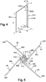
- the figure 4 illustrates an isolated element 3A of the hanger device 1.
- the proximal edge 31A has three lugs 310A, 311A and 312A. These flanges are flat rectangular portions of length "l" of 20 cm formed by the successive folding of the steel sheet, with an angle ⁇ of 90 ° from one pan to the next, leaving a space 300A of width L greater than the diameter of the rod 2 which makes it possible to fit the element 3A on the rod 2 (not shown).
- each panel 310A, 311A and 312A in a horizontal plane transverse to the rod, is such that the diameter of the sleeve 4 formed by the complementarity of the edges 31A to 31D ( figure 5 ), is slightly greater than the diameter of the stem.
- This width of each pan is different from one pan to another, so that they are suitable for fitting ( figure 5 ) with the panels 310B, 311B, 312B; 310C, 311C, 312C; 310D, 311D, 312D respectively, other planar elements 3B, 3C and 3D.
- the pan 312A has a width of preferably 0.7 cm, the pan 311 A has a width preferably of 1.2 cm, while the end pan 310A extends in a direction transverse to the sleeve 4 (or the rod 2 ), by its free end 32A, to form the rectangular planar element 3A, preferably of a width of 5.5 cm.
- the figure 5 shows from above the rod 2 and the four bracing elements 3A to 3D, from the figure 3 , said elements 3A to 3D being nested in each other, each at their three 90 ° faces, on the rod 2 by their ends 31A to 31D, to form an orthogonal side brace.
- the sleeve 4 is thus delimited by four orthogonal 40A to 40D sides, each consisting of three parallel faces 310, 311 and 312, belonging to a different bracing element 3A to 3D.
- the panels 310, 311 and 312 of each bracing element 3A to 3D are not represented on the figure 5 for readability issues.
- the side 40A consists, from the outside towards the inside, of the panels 310A, 311D and 312C; the side 40B consists of the panels 310B, 311A and 312D; the 40C side consists of the 310C, 311 B, 312A; the 40D side consists of the 310D, 311C, 312B.
- bracing elements 3A to 3D are able to slide longitudinally relative to each other along the longitudinal axis of the rod 2. They are nested between them freely, without friction.
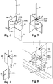
- the figure 7 shows that the rod 2 is also able to slide freely, without friction, longitudinally in the sleeve 4 (substantially square section), the four inner faces are constituted by proximal faces 312A, 312B, 312C and 312D.
- the element 3A is fitted into the element 3B by sliding them longitudinally relative to each other, the pan 312A being parallel to the pan 311B, and the pan 311 A being parallel to the pan 310B.
- the element 3C is fitted on the element 3B, the pan 310C being parallel to the panels 311 B and 312A and the pan 311C being parallel to the pan 312B.
- the 3D element is nested on the element 3C in the same way as previously, the pan 310D being parallel to the panels 311C and 312B, and the pan 311 D being parallel to the panels 312C and 310A.
- the sleeve 4 is delimited by the panels 312A to 312D near the rod 2 and the panels 310A to 310D away from the rod 2, the panels 311A to 311D being located between the two.
- the figure 8 illustrates the disassembly of the bracing system of a rod 2 whose length is at least twice the length "l" of the proximal edges 31 A to 31 D bracing elements 3A to 3D.
- the elements 3A to 3D are slid one after the other along the rod 2, downwards (towards the false ceiling 11, not shown), after unscrewing the lower nut. 8 of the stem 2.
Landscapes
- Engineering & Computer Science (AREA)
- Architecture (AREA)
- Physics & Mathematics (AREA)
- Electromagnetism (AREA)
- Civil Engineering (AREA)
- Structural Engineering (AREA)
- Joining Of Building Structures In Genera (AREA)
Priority Applications (1)
| Application Number | Priority Date | Filing Date | Title |
|---|---|---|---|
| SM20180252T SMT201800252T1 (it) | 2015-10-28 | 2016-10-11 | Dispositivo di collegamento di un soffitto sospeso ad una soletta |
Applications Claiming Priority (1)
| Application Number | Priority Date | Filing Date | Title |
|---|---|---|---|
| FR1560302A FR3043106B1 (fr) | 2015-10-28 | 2015-10-28 | Dispositif de liaison d’un plafond suspendu a une dalle |
Publications (2)
| Publication Number | Publication Date |
|---|---|
| EP3162973A1 true EP3162973A1 (de) | 2017-05-03 |
| EP3162973B1 EP3162973B1 (de) | 2018-04-11 |
Family
ID=55022577
Family Applications (1)
| Application Number | Title | Priority Date | Filing Date |
|---|---|---|---|
| EP16193373.4A Active EP3162973B1 (de) | 2015-10-28 | 2016-10-11 | Anschlussvorrichtung für eine decke, die an einer bodenplatte abgehängt ist |
Country Status (5)
| Country | Link |
|---|---|
| EP (1) | EP3162973B1 (de) |
| ES (1) | ES2670708T3 (de) |
| FR (1) | FR3043106B1 (de) |
| PT (1) | PT3162973T (de) |
| SM (1) | SMT201800252T1 (de) |
Citations (3)
| Publication number | Priority date | Publication date | Assignee | Title |
|---|---|---|---|---|
| DE2343713B1 (de) * | 1973-08-30 | 1975-01-02 | Artur Fischer | Aufhaengevorrichtung,insbesondere fuer eine Unterdecke |
| JP2015031081A (ja) * | 2013-08-05 | 2015-02-16 | 株式会社桐井製作所 | ブレース取付金具 |
| JP2015151762A (ja) * | 2014-02-14 | 2015-08-24 | 株式会社サワタ | 筋交いの取付装置 |
-
2015
- 2015-10-28 FR FR1560302A patent/FR3043106B1/fr active Active
-
2016
- 2016-10-11 ES ES16193373.4T patent/ES2670708T3/es active Active
- 2016-10-11 SM SM20180252T patent/SMT201800252T1/it unknown
- 2016-10-11 PT PT161933734T patent/PT3162973T/pt unknown
- 2016-10-11 EP EP16193373.4A patent/EP3162973B1/de active Active
Patent Citations (3)
| Publication number | Priority date | Publication date | Assignee | Title |
|---|---|---|---|---|
| DE2343713B1 (de) * | 1973-08-30 | 1975-01-02 | Artur Fischer | Aufhaengevorrichtung,insbesondere fuer eine Unterdecke |
| JP2015031081A (ja) * | 2013-08-05 | 2015-02-16 | 株式会社桐井製作所 | ブレース取付金具 |
| JP2015151762A (ja) * | 2014-02-14 | 2015-08-24 | 株式会社サワタ | 筋交いの取付装置 |
Also Published As
| Publication number | Publication date |
|---|---|
| ES2670708T3 (es) | 2018-05-31 |
| FR3043106B1 (fr) | 2019-08-16 |
| PT3162973T (pt) | 2018-05-24 |
| EP3162973B1 (de) | 2018-04-11 |
| FR3043106A1 (fr) | 2017-05-05 |
| SMT201800252T1 (it) | 2018-07-17 |
Similar Documents
| Publication | Publication Date | Title |
|---|---|---|
| FR2546953A1 (fr) | Construction demontable, notamment pour exposition temporaire | |
| WO1996002716A1 (fr) | Escalier a configuration variable | |
| FR2971535A1 (fr) | Cloture du genre comprenant des panneaux associes a des poteaux porteurs | |
| EP3162973B1 (de) | Anschlussvorrichtung für eine decke, die an einer bodenplatte abgehängt ist | |
| WO2018073534A1 (fr) | Montant telescopique pour un systeme d'obturation d'une ouverture, systeme d'obturation et procédé de mise en oeuvre | |
| FR2458640A1 (fr) | Faux-plafond metallique | |
| EP0651112A1 (de) | Modulaires Geländer mit horizontalen oder geneigten Holmen | |
| EP3017121B1 (de) | Abschnitt mit lippe und zungen und zugehöriger abstandshalter | |
| FR3025503A1 (fr) | Ensemble de construction pour pylone d’ascenseur et pylone d’ascenseur associe | |
| FR3034823A1 (fr) | Dispositif de liaison de profiles, notamment pour la realisation de structures et plus particulierement de pergolas, structures obtenues | |
| FR3057886A1 (fr) | Systeme de parement, ensemble de parement d'au moins deux systemes de parement superposes, et cloison, parement et cloture comprenant au moins un ensemble de parement | |
| FR3076874A1 (fr) | Cale d’assemblage d’une structure a base de profiles metalliques | |
| BE1006773A5 (fr) | Armature, construction contenant une telle armature, habillage et noeud pour une telle armature. | |
| FR2688016A1 (fr) | Agencement pour l'amenagement d'une cloison. | |
| FR2664633A1 (fr) | Plafond suspendu. | |
| EP3550089B1 (de) | Kit für entfernbare trennwand | |
| FR2820769A1 (fr) | Panneau garde-corps de securite | |
| EP3748097B1 (de) | Metallrahmen für vorgefertigte trockenbau-platten | |
| FR2970017A1 (fr) | Dispositif pour l'assemblage d'une marche sur un support | |
| EP3240934A1 (de) | Verfahren zum isolieren und entsprechendes aufhängungselement und anordnung | |
| FR2963041A1 (fr) | Passerelle de securite | |
| FR2932874A1 (fr) | Chaise pour foyer de cheminee | |
| FR3013800A1 (fr) | Montant telescopique pour la realisation d'une paroi murale, profile et procede de montage | |
| FR3001748A1 (fr) | Dispositif pour realiser un doublage le long d'un mur existant, en matiere legere coulee par paliers ou en lits successifs, dans un coffrage | |
| FR2991696A1 (fr) | Ossature de plancher pour construction de preference modulaire |
Legal Events
| Date | Code | Title | Description |
|---|---|---|---|
| PUAI | Public reference made under article 153(3) epc to a published international application that has entered the european phase |
Free format text: ORIGINAL CODE: 0009012 |
|
| AK | Designated contracting states |
Kind code of ref document: A1 Designated state(s): AL AT BE BG CH CY CZ DE DK EE ES FI FR GB GR HR HU IE IS IT LI LT LU LV MC MK MT NL NO PL PT RO RS SE SI SK SM TR |
|
| AX | Request for extension of the european patent |
Extension state: BA ME |
|
| 17P | Request for examination filed |
Effective date: 20170718 |
|
| RBV | Designated contracting states (corrected) |
Designated state(s): AL AT BE BG CH CY CZ DE DK EE ES FI FR GB GR HR HU IE IS IT LI LT LU LV MC MK MT NL NO PL PT RO RS SE SI SK SM TR |
|
| GRAP | Despatch of communication of intention to grant a patent |
Free format text: ORIGINAL CODE: EPIDOSNIGR1 |
|
| INTG | Intention to grant announced |
Effective date: 20171102 |
|
| GRAS | Grant fee paid |
Free format text: ORIGINAL CODE: EPIDOSNIGR3 |
|
| GRAA | (expected) grant |
Free format text: ORIGINAL CODE: 0009210 |
|
| AK | Designated contracting states |
Kind code of ref document: B1 Designated state(s): AL AT BE BG CH CY CZ DE DK EE ES FI FR GB GR HR HU IE IS IT LI LT LU LV MC MK MT NL NO PL PT RO RS SE SI SK SM TR |
|
| REG | Reference to a national code |
Ref country code: GB Ref legal event code: FG4D Free format text: NOT ENGLISH |
|
| REG | Reference to a national code |
Ref country code: CH Ref legal event code: EP |
|
| REG | Reference to a national code |
Ref country code: AT Ref legal event code: REF Ref document number: 988181 Country of ref document: AT Kind code of ref document: T Effective date: 20180415 |
|
| REG | Reference to a national code |
Ref country code: IE Ref legal event code: FG4D Free format text: LANGUAGE OF EP DOCUMENT: FRENCH |
|
| REG | Reference to a national code |
Ref country code: DE Ref legal event code: R096 Ref document number: 602016002376 Country of ref document: DE |
|
| REG | Reference to a national code |
Ref country code: PT Ref legal event code: SC4A Ref document number: 3162973 Country of ref document: PT Date of ref document: 20180524 Kind code of ref document: T Free format text: AVAILABILITY OF NATIONAL TRANSLATION Effective date: 20180518 |
|
| REG | Reference to a national code |
Ref country code: ES Ref legal event code: FG2A Ref document number: 2670708 Country of ref document: ES Kind code of ref document: T3 Effective date: 20180531 |
|
| REG | Reference to a national code |
Ref country code: NL Ref legal event code: FP |
|
| REG | Reference to a national code |
Ref country code: LT Ref legal event code: MG4D |
|
| PG25 | Lapsed in a contracting state [announced via postgrant information from national office to epo] |
Ref country code: BG Free format text: LAPSE BECAUSE OF FAILURE TO SUBMIT A TRANSLATION OF THE DESCRIPTION OR TO PAY THE FEE WITHIN THE PRESCRIBED TIME-LIMIT Effective date: 20180711 Ref country code: FI Free format text: LAPSE BECAUSE OF FAILURE TO SUBMIT A TRANSLATION OF THE DESCRIPTION OR TO PAY THE FEE WITHIN THE PRESCRIBED TIME-LIMIT Effective date: 20180411 Ref country code: NO Free format text: LAPSE BECAUSE OF FAILURE TO SUBMIT A TRANSLATION OF THE DESCRIPTION OR TO PAY THE FEE WITHIN THE PRESCRIBED TIME-LIMIT Effective date: 20180711 Ref country code: SE Free format text: LAPSE BECAUSE OF FAILURE TO SUBMIT A TRANSLATION OF THE DESCRIPTION OR TO PAY THE FEE WITHIN THE PRESCRIBED TIME-LIMIT Effective date: 20180411 Ref country code: AL Free format text: LAPSE BECAUSE OF FAILURE TO SUBMIT A TRANSLATION OF THE DESCRIPTION OR TO PAY THE FEE WITHIN THE PRESCRIBED TIME-LIMIT Effective date: 20180411 Ref country code: LT Free format text: LAPSE BECAUSE OF FAILURE TO SUBMIT A TRANSLATION OF THE DESCRIPTION OR TO PAY THE FEE WITHIN THE PRESCRIBED TIME-LIMIT Effective date: 20180411 Ref country code: PL Free format text: LAPSE BECAUSE OF FAILURE TO SUBMIT A TRANSLATION OF THE DESCRIPTION OR TO PAY THE FEE WITHIN THE PRESCRIBED TIME-LIMIT Effective date: 20180411 |
|
| REG | Reference to a national code |
Ref country code: FR Ref legal event code: PLFP Year of fee payment: 3 |
|
| PG25 | Lapsed in a contracting state [announced via postgrant information from national office to epo] |
Ref country code: LV Free format text: LAPSE BECAUSE OF FAILURE TO SUBMIT A TRANSLATION OF THE DESCRIPTION OR TO PAY THE FEE WITHIN THE PRESCRIBED TIME-LIMIT Effective date: 20180411 Ref country code: RS Free format text: LAPSE BECAUSE OF FAILURE TO SUBMIT A TRANSLATION OF THE DESCRIPTION OR TO PAY THE FEE WITHIN THE PRESCRIBED TIME-LIMIT Effective date: 20180411 Ref country code: GR Free format text: LAPSE BECAUSE OF FAILURE TO SUBMIT A TRANSLATION OF THE DESCRIPTION OR TO PAY THE FEE WITHIN THE PRESCRIBED TIME-LIMIT Effective date: 20180712 Ref country code: HR Free format text: LAPSE BECAUSE OF FAILURE TO SUBMIT A TRANSLATION OF THE DESCRIPTION OR TO PAY THE FEE WITHIN THE PRESCRIBED TIME-LIMIT Effective date: 20180411 |
|
| REG | Reference to a national code |
Ref country code: AT Ref legal event code: MK05 Ref document number: 988181 Country of ref document: AT Kind code of ref document: T Effective date: 20180411 |
|
| REG | Reference to a national code |
Ref country code: DE Ref legal event code: R097 Ref document number: 602016002376 Country of ref document: DE |
|
| PG25 | Lapsed in a contracting state [announced via postgrant information from national office to epo] |
Ref country code: AT Free format text: LAPSE BECAUSE OF FAILURE TO SUBMIT A TRANSLATION OF THE DESCRIPTION OR TO PAY THE FEE WITHIN THE PRESCRIBED TIME-LIMIT Effective date: 20180411 Ref country code: EE Free format text: LAPSE BECAUSE OF FAILURE TO SUBMIT A TRANSLATION OF THE DESCRIPTION OR TO PAY THE FEE WITHIN THE PRESCRIBED TIME-LIMIT Effective date: 20180411 Ref country code: RO Free format text: LAPSE BECAUSE OF FAILURE TO SUBMIT A TRANSLATION OF THE DESCRIPTION OR TO PAY THE FEE WITHIN THE PRESCRIBED TIME-LIMIT Effective date: 20180411 Ref country code: SK Free format text: LAPSE BECAUSE OF FAILURE TO SUBMIT A TRANSLATION OF THE DESCRIPTION OR TO PAY THE FEE WITHIN THE PRESCRIBED TIME-LIMIT Effective date: 20180411 Ref country code: DK Free format text: LAPSE BECAUSE OF FAILURE TO SUBMIT A TRANSLATION OF THE DESCRIPTION OR TO PAY THE FEE WITHIN THE PRESCRIBED TIME-LIMIT Effective date: 20180411 |
|
| PLBE | No opposition filed within time limit |
Free format text: ORIGINAL CODE: 0009261 |
|
| STAA | Information on the status of an ep patent application or granted ep patent |
Free format text: STATUS: NO OPPOSITION FILED WITHIN TIME LIMIT |
|
| 26N | No opposition filed |
Effective date: 20190114 |
|
| PG25 | Lapsed in a contracting state [announced via postgrant information from national office to epo] |
Ref country code: SI Free format text: LAPSE BECAUSE OF FAILURE TO SUBMIT A TRANSLATION OF THE DESCRIPTION OR TO PAY THE FEE WITHIN THE PRESCRIBED TIME-LIMIT Effective date: 20180411 |
|
| REG | Reference to a national code |
Ref country code: IE Ref legal event code: MM4A |
|
| PG25 | Lapsed in a contracting state [announced via postgrant information from national office to epo] |
Ref country code: IE Free format text: LAPSE BECAUSE OF NON-PAYMENT OF DUE FEES Effective date: 20181011 |
|
| PG25 | Lapsed in a contracting state [announced via postgrant information from national office to epo] |
Ref country code: MT Free format text: LAPSE BECAUSE OF FAILURE TO SUBMIT A TRANSLATION OF THE DESCRIPTION OR TO PAY THE FEE WITHIN THE PRESCRIBED TIME-LIMIT Effective date: 20180411 |
|
| PG25 | Lapsed in a contracting state [announced via postgrant information from national office to epo] |
Ref country code: TR Free format text: LAPSE BECAUSE OF FAILURE TO SUBMIT A TRANSLATION OF THE DESCRIPTION OR TO PAY THE FEE WITHIN THE PRESCRIBED TIME-LIMIT Effective date: 20180411 |
|
| REG | Reference to a national code |
Ref country code: CH Ref legal event code: PL |
|
| PG25 | Lapsed in a contracting state [announced via postgrant information from national office to epo] |
Ref country code: MK Free format text: LAPSE BECAUSE OF NON-PAYMENT OF DUE FEES Effective date: 20180411 Ref country code: HU Free format text: LAPSE BECAUSE OF FAILURE TO SUBMIT A TRANSLATION OF THE DESCRIPTION OR TO PAY THE FEE WITHIN THE PRESCRIBED TIME-LIMIT; INVALID AB INITIO Effective date: 20161011 Ref country code: CY Free format text: LAPSE BECAUSE OF FAILURE TO SUBMIT A TRANSLATION OF THE DESCRIPTION OR TO PAY THE FEE WITHIN THE PRESCRIBED TIME-LIMIT Effective date: 20180411 |
|
| PG25 | Lapsed in a contracting state [announced via postgrant information from national office to epo] |
Ref country code: CH Free format text: LAPSE BECAUSE OF NON-PAYMENT OF DUE FEES Effective date: 20191031 Ref country code: LI Free format text: LAPSE BECAUSE OF NON-PAYMENT OF DUE FEES Effective date: 20191031 Ref country code: IS Free format text: LAPSE BECAUSE OF FAILURE TO SUBMIT A TRANSLATION OF THE DESCRIPTION OR TO PAY THE FEE WITHIN THE PRESCRIBED TIME-LIMIT Effective date: 20180811 |
|
| P01 | Opt-out of the competence of the unified patent court (upc) registered |
Effective date: 20230420 |
|
| PGFP | Annual fee paid to national office [announced via postgrant information from national office to epo] |
Ref country code: LU Payment date: 20251028 Year of fee payment: 10 Ref country code: NL Payment date: 20251029 Year of fee payment: 10 |
|
| PGFP | Annual fee paid to national office [announced via postgrant information from national office to epo] |
Ref country code: PT Payment date: 20251008 Year of fee payment: 10 |
|
| PGFP | Annual fee paid to national office [announced via postgrant information from national office to epo] |
Ref country code: DE Payment date: 20251029 Year of fee payment: 10 |
|
| PGFP | Annual fee paid to national office [announced via postgrant information from national office to epo] |
Ref country code: GB Payment date: 20251028 Year of fee payment: 10 |
|
| PGFP | Annual fee paid to national office [announced via postgrant information from national office to epo] |
Ref country code: MC Payment date: 20251030 Year of fee payment: 10 |
|
| PGFP | Annual fee paid to national office [announced via postgrant information from national office to epo] |
Ref country code: SM Payment date: 20251027 Year of fee payment: 10 |
|
| PGFP | Annual fee paid to national office [announced via postgrant information from national office to epo] |
Ref country code: IT Payment date: 20251029 Year of fee payment: 10 |
|
| PGFP | Annual fee paid to national office [announced via postgrant information from national office to epo] |
Ref country code: FR Payment date: 20251028 Year of fee payment: 10 |
|
| PGFP | Annual fee paid to national office [announced via postgrant information from national office to epo] |
Ref country code: BE Payment date: 20251029 Year of fee payment: 10 |
|
| PGFP | Annual fee paid to national office [announced via postgrant information from national office to epo] |
Ref country code: CZ Payment date: 20251009 Year of fee payment: 10 |
|
| PGFP | Annual fee paid to national office [announced via postgrant information from national office to epo] |
Ref country code: ES Payment date: 20251103 Year of fee payment: 10 |