EP3163232A1 - Appareil frigorifique comprenant une partie d'intégration arrière et procédé de fabrication d'un appareil frigorifique comprenant une partie d'intégration arrière - Google Patents
Appareil frigorifique comprenant une partie d'intégration arrière et procédé de fabrication d'un appareil frigorifique comprenant une partie d'intégration arrière Download PDFInfo
- Publication number
- EP3163232A1 EP3163232A1 EP16192505.2A EP16192505A EP3163232A1 EP 3163232 A1 EP3163232 A1 EP 3163232A1 EP 16192505 A EP16192505 A EP 16192505A EP 3163232 A1 EP3163232 A1 EP 3163232A1
- Authority
- EP
- European Patent Office
- Prior art keywords
- wall
- opening
- holding means
- refrigerating appliance
- spring arm
- Prior art date
- Legal status (The legal status is an assumption and is not a legal conclusion. Google has not performed a legal analysis and makes no representation as to the accuracy of the status listed.)
- Granted
Links
Images
Classifications
-
- F—MECHANICAL ENGINEERING; LIGHTING; HEATING; WEAPONS; BLASTING
- F25—REFRIGERATION OR COOLING; COMBINED HEATING AND REFRIGERATION SYSTEMS; HEAT PUMP SYSTEMS; MANUFACTURE OR STORAGE OF ICE; LIQUEFACTION SOLIDIFICATION OF GASES
- F25D—REFRIGERATORS; COLD ROOMS; ICE-BOXES; COOLING OR FREEZING APPARATUS NOT OTHERWISE PROVIDED FOR
- F25D23/00—General constructional features
- F25D23/06—Walls
- F25D23/062—Walls defining a cabinet
- F25D23/063—Walls defining a cabinet formed by an assembly of panels
-
- F—MECHANICAL ENGINEERING; LIGHTING; HEATING; WEAPONS; BLASTING
- F25—REFRIGERATION OR COOLING; COMBINED HEATING AND REFRIGERATION SYSTEMS; HEAT PUMP SYSTEMS; MANUFACTURE OR STORAGE OF ICE; LIQUEFACTION SOLIDIFICATION OF GASES
- F25D—REFRIGERATORS; COLD ROOMS; ICE-BOXES; COOLING OR FREEZING APPARATUS NOT OTHERWISE PROVIDED FOR
- F25D23/00—General constructional features
- F25D23/06—Walls
- F25D23/065—Details
-
- F—MECHANICAL ENGINEERING; LIGHTING; HEATING; WEAPONS; BLASTING
- F25—REFRIGERATION OR COOLING; COMBINED HEATING AND REFRIGERATION SYSTEMS; HEAT PUMP SYSTEMS; MANUFACTURE OR STORAGE OF ICE; LIQUEFACTION SOLIDIFICATION OF GASES
- F25D—REFRIGERATORS; COLD ROOMS; ICE-BOXES; COOLING OR FREEZING APPARATUS NOT OTHERWISE PROVIDED FOR
- F25D11/00—Self-contained movable devices, e.g. domestic refrigerators
- F25D11/02—Self-contained movable devices, e.g. domestic refrigerators with cooling compartments at different temperatures
-
- F—MECHANICAL ENGINEERING; LIGHTING; HEATING; WEAPONS; BLASTING
- F25—REFRIGERATION OR COOLING; COMBINED HEATING AND REFRIGERATION SYSTEMS; HEAT PUMP SYSTEMS; MANUFACTURE OR STORAGE OF ICE; LIQUEFACTION SOLIDIFICATION OF GASES
- F25D—REFRIGERATORS; COLD ROOMS; ICE-BOXES; COOLING OR FREEZING APPARATUS NOT OTHERWISE PROVIDED FOR
- F25D23/00—General constructional features
- F25D23/02—Doors; Covers
-
- F—MECHANICAL ENGINEERING; LIGHTING; HEATING; WEAPONS; BLASTING
- F25—REFRIGERATION OR COOLING; COMBINED HEATING AND REFRIGERATION SYSTEMS; HEAT PUMP SYSTEMS; MANUFACTURE OR STORAGE OF ICE; LIQUEFACTION SOLIDIFICATION OF GASES
- F25D—REFRIGERATORS; COLD ROOMS; ICE-BOXES; COOLING OR FREEZING APPARATUS NOT OTHERWISE PROVIDED FOR
- F25D23/00—General constructional features
- F25D23/02—Doors; Covers
- F25D23/028—Details
-
- F—MECHANICAL ENGINEERING; LIGHTING; HEATING; WEAPONS; BLASTING
- F25—REFRIGERATION OR COOLING; COMBINED HEATING AND REFRIGERATION SYSTEMS; HEAT PUMP SYSTEMS; MANUFACTURE OR STORAGE OF ICE; LIQUEFACTION SOLIDIFICATION OF GASES
- F25D—REFRIGERATORS; COLD ROOMS; ICE-BOXES; COOLING OR FREEZING APPARATUS NOT OTHERWISE PROVIDED FOR
- F25D23/00—General constructional features
- F25D23/08—Parts formed wholly or mainly of plastics materials
-
- F—MECHANICAL ENGINEERING; LIGHTING; HEATING; WEAPONS; BLASTING
- F25—REFRIGERATION OR COOLING; COMBINED HEATING AND REFRIGERATION SYSTEMS; HEAT PUMP SYSTEMS; MANUFACTURE OR STORAGE OF ICE; LIQUEFACTION SOLIDIFICATION OF GASES
- F25D—REFRIGERATORS; COLD ROOMS; ICE-BOXES; COOLING OR FREEZING APPARATUS NOT OTHERWISE PROVIDED FOR
- F25D23/00—General constructional features
- F25D23/10—Arrangements for mounting in particular locations, e.g. for built-in type, for corner type
-
- F—MECHANICAL ENGINEERING; LIGHTING; HEATING; WEAPONS; BLASTING
- F25—REFRIGERATION OR COOLING; COMBINED HEATING AND REFRIGERATION SYSTEMS; HEAT PUMP SYSTEMS; MANUFACTURE OR STORAGE OF ICE; LIQUEFACTION SOLIDIFICATION OF GASES
- F25D—REFRIGERATORS; COLD ROOMS; ICE-BOXES; COOLING OR FREEZING APPARATUS NOT OTHERWISE PROVIDED FOR
- F25D2201/00—Insulation
-
- F—MECHANICAL ENGINEERING; LIGHTING; HEATING; WEAPONS; BLASTING
- F25—REFRIGERATION OR COOLING; COMBINED HEATING AND REFRIGERATION SYSTEMS; HEAT PUMP SYSTEMS; MANUFACTURE OR STORAGE OF ICE; LIQUEFACTION SOLIDIFICATION OF GASES
- F25D—REFRIGERATORS; COLD ROOMS; ICE-BOXES; COOLING OR FREEZING APPARATUS NOT OTHERWISE PROVIDED FOR
- F25D2201/00—Insulation
- F25D2201/10—Insulation with respect to heat
Definitions
- the invention relates to a refrigeration appliance, in particular domestic refrigeration appliance, with a body and a door, each defining a cavity at least partially filled with insulation material by a wall, further with a backing part, which rests on the insulation side on a back of the wall and an opening of the wall opposite to a Sealing outlet of insulating material seals.
- the invention further relates to a method for producing a refrigeration device.
- the wall of the body bounding the cavity filled with insulation material comprises a thin-walled plastic inner wall produced by thermoforming. This inner wall forms the inner container of the refrigerator.
- the wall of the body further comprises an outer wall, which are formed for example by thin-walled sheets as side walls, multi-layer cardboard boxes as rear walls or plastic injection molded as floor walls.
- the cured insulation material Although sufficient stability of the refrigerator is made possible by the cured insulation material. However, in order to attach more components to a portion of the wall, it may be necessary to place at this point a backing part within the cavity. If the other component is screwed to the wall, the screw passing through the wall can be screwed into the backing part. The other component can thus be stably mounted on the wall.
- a simple way to position the backing part within the cavity before the introduction of the insulating material is to attach the backing part by means of adhesive tape to a rear side of the wall.
- the object of the present invention is to provide a generic refrigeration device and to provide a method for producing a refrigeration device, wherein the assembly of the backing part should be simple and accurate.
- the object is achieved by a refrigeration device described in the introduction, characterized in that the backing part is anchored to an opening of a disposed within the cavity portion of a wall element of the wall with a arranged on a spring arm holding means.
- the wall element is a component which forms the wall at least in regions.
- the arranged within the cavity portion is preferably in one piece, and more preferably also einmaterialig, formed on the wall element, more preferably, the entire wall element is preferably formed in one piece and einstoffig. The arranged in the cavity portion of the wall element does not contribute to the formation of the wall.
- This section is preferably partially or completely in contact with the insulating material.
- the invention is based on the recognition that on the one hand in the manufacture of the wall element the breakthrough be introduced in a simple manner.
- the spring arm according to the invention now allows that production-related Tolerances in the insertion of the breakthrough to no influence on the secure anchoring of the backing part on the wall element lead. Rather, the backing part is securely pressed by means of the spring force generated by the spring arm in the unexpanded state of the cavity against the rear wall. Undesirable gaps between the backing piece and the outer wall through which insulation material could escape are avoided. The position of the backing part is moreover securely held during the introduction and curing of the insulating material.
- the holding means on the spring arm that the mounting of the backing part is simple and safe to carry out.
- This can be anchored by hand to the breakthrough and by means of the spring force generated by the spring arm, it is securely and reliably held in position.
- Reworking in the anchoring of the backing part e.g. Due to production-related position and / or shape deviations of the breakthrough, are not necessary.
- the backing part remains in position until the isolation material is introduced and stabilized by the cured insulation material.
- the wall element is a sheet metal and the portion disposed within the cavity is a folded edge of the sheet metal.
- the aperture is preferably punched.
- the wall element at least partially forms an outer wall of the body and that the portion constitutes a boundary wall of a groove for receiving an inner container.
- the wall element forms a side wall of the body.
- the groove preferably extends substantially completely along an extent, e.g. Height extension or width extension, a storage room of the refrigerator.
- the holding means is used to hold the backing part in the unexpanded state of the cavity, that is, during production, captive on the wall portion.
- the holding means is a headband, which engages behind a wall portion surrounding the breakthrough.
- the holding means is especially hacked into the breakthrough.
- the headband on an elongated shape, ie its longitudinal extent is greater than its width or height extent.
- the retaining bracket is fastened by means of a transverse web to the spring arm and protrudes from the transverse web substantially at right angles.
- the crosspiece penetrates the opening and further preferably, the crosspiece is located at an edge of the opening.
- the transverse web can be pressed by means of the spring force generated by the spring arm against an edge of the opening.
- the headband itself may contact a wall portion surrounding the aperture of the wall element.
- the headband does not contact this wall section or contacted only in sections and only by its engagement behind represents a positive connection to prevent accidental displacement of the backing part before foaming the cavity.
- Both the headband and the crosspiece can be formed by flat components (wall thickness is less than the other two extensions) and can in particular have a same wall thickness and lie in one plane. The flat shape favors the manufacture and easy threading in the breakthrough.
- the retaining clip engages behind the wall section by an extent whose amount amounts to at least 10%, preferably at least 20% and more preferably at least 30%, of the opening width of the aperture measured in the longitudinal direction of the retaining clip.
- the retaining bracket is an elongate component, the longitudinal extent of which engages behind the wall portion accordingly.
- a secure mounting can be realized despite the overall small footprint of the backing part. It is particularly advantageous in this embodiment - but also in principle in the other embodiments with respect to the headband - when the breakthrough at a first end portion has an extension region. The extension area increases a clear distance between two opposite edges of the aperture.
- a further simplification of the assembly can be achieved if it is provided according to an embodiment that a free end portion of the retaining clip has an insertion bevel.
- the holding means is a latching lug which is latched to an edge bordering the breakthrough.
- the locking lug can in particular serve to fix a already elsewhere positioned backing part in its position. By locking the detent on the edge of the corresponding spring arm is tensioned, i. generates the force that presses the backing part against the back wall.
- the locking lug is preferably latched to an edge of the opening, which is the most remote from the opening of the outer wall in order to maximally clamp the spring arm.
- the portion of the wall element, which has the aperture, is disposed within the cavity, for example formed by a groove for receiving an inner container, this portion may be in contact on both sides or on one side (only one of its two main surfaces) with insulating material. In any case, however, none of its surfaces forms the wall of the refrigerator, even in sections, from. However, it may be advantageous to prevent or at least complicate a passage of insulation material through the introduced only for the purpose of anchoring the Schulegmaschines breakthrough.
- the backing part has a cover body, in particular formed by a cover wall, which shields the breakthrough against passage of insulating material, at least as far as possible.
- the cover body or the cover wall can either, at least as far as possible, bear against a section of the wall element delimiting the opening. It is also conceivable that the cover body or the cover wall form a gap with this section, the sufficient to prevent excessive passage of insulation material.
- the cover body or the cover wall on the one hand and the holding means on the other hand are arranged on two different sides of the portion of the wall element.
- the holding means is arranged on the cover body.
- the holding means may protrude from the cover body or the cover wall, preferably protrude perpendicularly from it, and / or be surrounded by it on all sides.
- the cover body or the cover wall has a raised portion directed towards the portion of the wall element, e.g. a protruding rib.
- the survey is formed separately from the holding means. It contacts the section of the wall element and improves the contact pressure of the backing part on the rear wall in the unexpanded state of the cavity.
- both the headband and an edge region of the cover body or the cover wall can have an insertion bevel.
- the backing part has a contact section, preferably in the form of a sealing screen, which bears against the rear side of the wall.
- the backing part has a first spring arm with a first holding means and a second spring arm with a second holding means, and that the backing part is anchored by the holding means to a first opening and a separate second opening.
- the first and second apertures are disposed on a portion of a wall member of the wall disposed within the cavity.
- these are one and the same wall element.
- the two spring arms are arranged on opposite end portions of the backing part and more preferably the backing piece is in contact with a contact portion, eg a sealing screen, on the rear wall, which is substantially between the two end portions located.
- the two spring arms are identical or substantially identical; the two holding means may also be identical or substantially identical.
- the two holding means may also be identical or substantially identical.
- the assembly is further simplified by the first holding means for positioning and anchoring the backing part is used at the first opening and the second holding means thereafter serves for final anchoring of the backing part to the second opening.
- the two openings are preferably formed differently.
- the first breakthrough may have an extension region.
- the wall has two separately formed openings for attachment of the additional component, by one and the same Schulegteil against a passage of insulation material are covered.
- the wall has a first opening and a second opening and the backing part rests with a first sealing screen and a second sealing screen on the rear side of the wall and seals the openings with respect to an outlet of insulating material.
- a central portion of the backing part which is located between the sealing screens, has a reinforcing rib.
- the first spring arm and the second spring arm are arranged outside the center section at opposite end sections of the center section, so that the contact pressure in the region of the two sealing screens is made uniform.
- a simple assembly in particular a one-hand assembly, is achieved by providing according to an embodiment that the first holding means in a first joining direction, in particular a parallel to a main extension direction of the wall element, is inserted into the first opening and that the second holding means in a second Joining direction, which is substantially perpendicular to the first joining direction, which is in particular substantially perpendicular to the main extension direction of the wall element, is insertable into the second opening.
- the wall element is, for example, a side wall of the refrigeration device (outer wall)
- the main extension plane corresponds to the plane in which the side wall lies.
- Under joining direction here is preferably to understand the direction of movement in the last moment before the respective anchoring.
- the second holding means can undergo a pivoting movement during the complete working step of anchoring, the last movement sequence of which runs essentially perpendicular to the first joining direction.
- the first joining direction can be a linear movement (displacement), in particular during the complete step of anchoring.
- the backing part has a fastening portion for fastening an additional component which can be fastened to the outer wall.
- the attachment portion may be formed for example by a blind hole or a threaded hole.
- the soirbauteill example a connecting element for connecting the outer wall of the refrigerator with a wall of a furniture niche in which the refrigerator is installed. In the simplest case, this is the connection element to a metal plate, which is attached on the one hand to the refrigerator by means of the mounting portion, and on the other hand attached to the wall of the furniture niche, for. screwed on.
- the backing member is preferably located entirely within the cavity. In particular, the backing part does not protrude through the opening.
- the backing part is preferably formed in one piece and einstoffig.
- the backing part is a plastic component, more preferably an injection-molded component.
- the breakthrough is in particular an edge-closed opening of the section.
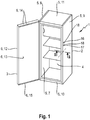
- Fig. 1 shows a schematic representation of a refrigerator according to the invention, in the form of a refrigerator 1, namely a built-in refrigerator.
- the refrigerator 1 has a body 2 and a hinged door 3, which together define a storage space 4 for refrigerated goods.
- Both the body 2 and the door 3 each have a wall 5, 6, each defining a cavity.
- the cavities of body 2 and door 3 are foamed with polyurethane foam as insulation material.
- the wall 5 of the body comprises as a boundary of the storage space 4, an inner wall which is formed by an inner container 7.
- This wall 5 further comprises as outer wall two side walls 8, 9, a bottom wall 10, a top wall 11 and a non-visible rear wall.
- the wall 6 of the door 3 comprises a door outer wall 12, a door inner wall 13 and an upper door closure strip 14 and a lower door closure strip 15.
- the inner container 7 and inner door wall 13 are plastic components, which are made by thermoforming of a thin-walled plastic blank.
- the side walls 8, 9 of the body are made of sheet metal.
- openings 16, 17 can be seen behind which a backing piece 18 is arranged.
- the openings 16, 17 were punched out.
- the backing part 18 abuts a rear side of the side wall 9 and thus prevents leakage of the insulating material through the openings 16, 17.
- These openings 16, 17 are used to attach the refrigerator 1 by means of an additional component to a wall of a furniture niche.
- the additional component such as a sheet metal element, with screws that penetrate the openings 16, 17 are screwed to the Schulegteil 18.
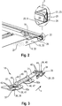
- Fig. 2 shows a section of a sectional view Fig. 1 along the cutting plane II-II.
- the backing piece 18 rests against the back side 19 of the side wall 9, it is not anchored to the side wall 9.
- the side wall 9 has a planar main surface 20, which forms a main plane of extension. Of this runs substantially perpendicular to a first folded edge 21 which abuts the inner container 7.
- the wall element 22, which forms, among other things, the side wall 9, has, in addition to the main surface 20 and the folded edge 21, a portion 23 which is located exclusively within the cavity 24.
- This section 23 forms a groove 25, in which an edge portion 26 of the inner container 7 is clamped.
- the groove 25 is substantially no insulation material 27th
- the backing part 18 has for anchoring two retaining means 29, 30 which are each arranged on a spring arm 31, 32.
- the first retaining means 29 is formed by a retaining clip 33.
- This retaining clip 33 has an elongated shape and is fastened by means of a transverse web 34 on the spring arm 31 and stands thereby from the transverse web 34 substantially at right angles.
- the headband 33 has at its free end an insertion bevel 35 in order to facilitate insertion into the corresponding opening.
- the second holding means 30 is formed by a latching nose 36. This stands by means of a Anlenkungsfußes 37 from the spring arm 32 and is turned in a direction opposite to the sealing screens described below.
- the spring arms 31, 32 each have a covering body 38, 39 in the form of a cover wall 40, 41.
- the cover walls 40, 41 are each formed on a lateral edge portion of the spring arms 31, 32 and oriented perpendicular thereto.
- the holding means 29, 30, in particular the Transverse web 34 and the Anlenkungsfuß 37 substantially perpendicular.
- the backing part 18 has in the region of the connection between the spring arms 31, 32 and the cover walls 40, 41 reinforcing ribs 42, 43 in order to avoid unwanted deformation of the cover walls 40, 41 when anchoring the backing part 18 in the openings.
- On both cover walls 40, 41 further surveys in the form of abutment ribs 44, 45 are formed, by means of which the backing part 18 can rest against the portion 23.
- the spring arms 31, 32 are disposed at opposite end portions of a center portion 46 of the backing member 18.
- the spring arms 31, 32 are formed by flat bracket with a rectangular cross-section.
- the central portion 46 is also substantially formed by a flat bracket 47 of rectangular cross-section, but additionally has a reinforcing rib 48 extending in the longitudinal direction X of the backing member.
- two screw domes 49 are attached, which serve as fastening sections for fastening an additional component.
- sealing screens 50 are arranged at that end of the screw mandrel 49, to which a screw can be screwed.
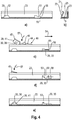
- Fig. 4 shows a schematic representation of the insertion of the backing part Fig. 3 What a mechanic can do with one hand.
- FIG. 4a Shown is Fig. 4a ) a section according to Fig. 4b ) by a section of the side wall 9.
- the engaging in the groove 25 edge portion 26 of the inner container 7 is not shown.
- the arranged within the cavity 24 section 23 of the side wall 9 has two openings 28, 51.
- the breakthrough 28 is designed to anchor the locking lug 36 formed as a holding means 30. It has substantially Reckeckige shape and is bordered by an edge 52.
- the opening 51 is designed to anchor the holding means 29, which is designed in the form of a retaining clip 33. This opening 51 has an extension area 53 for threading in the retaining clip 33 at one of its end sections.
- Fig. 4c Threading or insertion of the retaining clip 33 is shown in the opening 51.
- the backing part 18 can initially be slightly inclined for this purpose, so that the retaining clip 33 can be threaded smoothly. An excessive deformation of the spring arm 31 is not necessary.
- the headband 33 in Fig. 4c has taken position shown, so in particular already extends through the opening 51 in the groove 25, the Schulegteil 18 along the first joining direction 54 is linearly displaced. This shift takes place until the transverse web 34 contacts the edge 55 of the opening 51. In this position, the headband 33 engages behind a wall portion 56 surrounding the aperture 51 (see also Fig. 4d )).
- the retaining clip 33 engages behind the wall section 56 by an extension 58 whose amount is more than 30% of the opening width 59 of the opening 51 measured in the longitudinal direction of the retaining clip 33.
- the middle portion 46 and the spring arm 32 of the backing part 18 are pressed in the direction of the back 19, as in an intermediate position in Fig. 4d ) is recognizable.
- Both spring arms 31, 32 are tensioned.
- the spring arm 32 and with it the locking lug 36 are thereby moved along a second joining direction 57, namely pivoted.
- the second joining direction 57 extends substantially perpendicular to the first joining direction 54 and to the main extension plane of the side wall 9, as shown Fig. 4e ) is recognizable, which shows the anchored to the wall portion 26 backing 18.
Landscapes
- Engineering & Computer Science (AREA)
- Chemical & Material Sciences (AREA)
- Combustion & Propulsion (AREA)
- Physics & Mathematics (AREA)
- Mechanical Engineering (AREA)
- Thermal Sciences (AREA)
- General Engineering & Computer Science (AREA)
- Refrigerator Housings (AREA)
Applications Claiming Priority (1)
| Application Number | Priority Date | Filing Date | Title |
|---|---|---|---|
| DE102015221431.1A DE102015221431A1 (de) | 2015-11-02 | 2015-11-02 | Kältegerät mit Hinterlegteil und Verfahren zum Herstellen eines Kältegerätes mit Hinterlegteil |
Publications (2)
| Publication Number | Publication Date |
|---|---|
| EP3163232A1 true EP3163232A1 (fr) | 2017-05-03 |
| EP3163232B1 EP3163232B1 (fr) | 2021-01-13 |
Family
ID=57103891
Family Applications (1)
| Application Number | Title | Priority Date | Filing Date |
|---|---|---|---|
| EP16192505.2A Active EP3163232B1 (fr) | 2015-11-02 | 2016-10-06 | Appareil frigorifique comprenant une partie d'intégration arrière et procédé de fabrication d'un appareil frigorifique comprenant une partie d'intégration arrière |
Country Status (3)
| Country | Link |
|---|---|
| EP (1) | EP3163232B1 (fr) |
| CN (1) | CN106969585B (fr) |
| DE (1) | DE102015221431A1 (fr) |
Families Citing this family (1)
| Publication number | Priority date | Publication date | Assignee | Title |
|---|---|---|---|---|
| DE102021202364A1 (de) * | 2021-03-11 | 2022-09-15 | BSH Hausgeräte GmbH | Hinterlegteil für ein Haushaltskältegerätbauteil, Anordnung mit einem Haushaltskältegerätbauteil und einem Hinterlegteil, sowie Montageverfahren |
Citations (5)
| Publication number | Priority date | Publication date | Assignee | Title |
|---|---|---|---|---|
| DE19730357A1 (de) | 1997-07-15 | 1999-01-21 | Bosch Siemens Hausgeraete | Kühlgerät |
| JPH1151546A (ja) * | 1997-08-06 | 1999-02-26 | Matsushita Refrig Co Ltd | 冷凍冷蔵庫 |
| US6193455B1 (en) * | 1999-09-28 | 2001-02-27 | Illinois Tool Works Inc. | Blind screw anchor and system |
| DE102005057133A1 (de) * | 2005-11-30 | 2007-06-06 | BSH Bosch und Siemens Hausgeräte GmbH | Haushaltsgerät mit klemmgeschützter Tür |
| EP1950513A2 (fr) * | 2007-01-26 | 2008-07-30 | Samsung Gwangju Electronics Co., Ltd. | Réfrigérateur |
Family Cites Families (9)
| Publication number | Priority date | Publication date | Assignee | Title |
|---|---|---|---|---|
| US4474017A (en) * | 1982-09-07 | 1984-10-02 | General Electric Company | Method of assembling an anti-sweat heater in a refrigerator cabinet |
| JP2003336963A (ja) * | 2002-05-15 | 2003-11-28 | Toshiba Corp | 冷蔵庫 |
| DE102004012539A1 (de) * | 2004-03-15 | 2005-10-06 | BSH Bosch und Siemens Hausgeräte GmbH | Wärmeisolierende Wand |
| DE102004045475A1 (de) * | 2004-09-20 | 2006-03-30 | BSH Bosch und Siemens Hausgeräte GmbH | Bauteil zur Montage an einer hinterschäumten Wand und damit ausgestattetes Kältegerät |
| US8881466B2 (en) * | 2009-11-20 | 2014-11-11 | Ab Electrolux | Insulated door and method of assembling an insulated door |
| DE102010027918A1 (de) * | 2010-04-19 | 2011-10-20 | BSH Bosch und Siemens Hausgeräte GmbH | Türblatt, Verfahren zum Herstellen eines Türblatts und Kältegerät mit einem Türblatt |
| DE102010028414A1 (de) * | 2010-04-30 | 2011-11-03 | BSH Bosch und Siemens Hausgeräte GmbH | Kältegerät aufweisend ein Türblatt mit Griffschale |
| CN103105032B (zh) * | 2011-11-11 | 2019-09-20 | 博西华电器(江苏)有限公司 | 制冷器具 |
| CN104879980B (zh) * | 2015-05-29 | 2018-05-11 | 合肥华凌股份有限公司 | 冰箱 |
-
2015
- 2015-11-02 DE DE102015221431.1A patent/DE102015221431A1/de not_active Withdrawn
-
2016
- 2016-10-06 EP EP16192505.2A patent/EP3163232B1/fr active Active
- 2016-11-01 CN CN201610935383.0A patent/CN106969585B/zh active Active
Patent Citations (5)
| Publication number | Priority date | Publication date | Assignee | Title |
|---|---|---|---|---|
| DE19730357A1 (de) | 1997-07-15 | 1999-01-21 | Bosch Siemens Hausgeraete | Kühlgerät |
| JPH1151546A (ja) * | 1997-08-06 | 1999-02-26 | Matsushita Refrig Co Ltd | 冷凍冷蔵庫 |
| US6193455B1 (en) * | 1999-09-28 | 2001-02-27 | Illinois Tool Works Inc. | Blind screw anchor and system |
| DE102005057133A1 (de) * | 2005-11-30 | 2007-06-06 | BSH Bosch und Siemens Hausgeräte GmbH | Haushaltsgerät mit klemmgeschützter Tür |
| EP1950513A2 (fr) * | 2007-01-26 | 2008-07-30 | Samsung Gwangju Electronics Co., Ltd. | Réfrigérateur |
Also Published As
| Publication number | Publication date |
|---|---|
| DE102015221431A1 (de) | 2017-05-04 |
| CN106969585B (zh) | 2021-02-09 |
| CN106969585A (zh) | 2017-07-21 |
| EP3163232B1 (fr) | 2021-01-13 |
Similar Documents
| Publication | Publication Date | Title |
|---|---|---|
| WO2007122072A2 (fr) | Appareil ménager en plusieurs parties | |
| WO2008141995A2 (fr) | Appareil ménager | |
| EP2771953A1 (fr) | Insert de renfort d'angle | |
| EP2906888B1 (fr) | Réfrigérateur avec pièce intégrée | |
| EP3775727B1 (fr) | Appareil ménager avec une paroi ayant un element saillant d'accouplement pour l'accouplement avec une pièce intermédiaire disposée là-dessus, ainsi qu'une methode pour le montage de la pièce intermédiare sur la paroi | |
| WO2016165919A1 (fr) | Porte pour appareil ménager frigorifique comprenant une baguette de bord encliquetée, appareil ménager frigorifique et procédé de fabrication d'une porte | |
| EP3163232B1 (fr) | Appareil frigorifique comprenant une partie d'intégration arrière et procédé de fabrication d'un appareil frigorifique comprenant une partie d'intégration arrière | |
| EP3822562B1 (fr) | Armoire de climatisation | |
| WO2017036779A1 (fr) | Porte d'appareil électroménager et appareil électroménager pourvu d'une porte d'appareil électroménager | |
| DE102011084908A1 (de) | Kältegerät, insbesondere Haushaltskältegerät | |
| DE102014206948A1 (de) | Haushaltskältegerät | |
| DE102014203619A1 (de) | Haushaltsgerät | |
| DE102013220304A1 (de) | Haushaltsgerät mit einem eine Elektroniktasche und einen Deckel dazu aufweisenden Gehäuse | |
| DE102019216193A1 (de) | Haushaltsgerät mit einem Scharnier und Scharnier für ein Haushaltsgerät | |
| DE102005012714A1 (de) | Clipsystem zur Befestigung eines Anbauteils an einem Trägerteil | |
| EP0834656B1 (fr) | Dispositif de fixation d'un appareil contre une paroie, en particulier la paroie d'une carrosserie de véhicule automobile | |
| EP4056935A1 (fr) | Partie arrière de support pour un composant d'appareil de réfrigération électroménager, agencement doté d'un composant d'appareil de réfrigération électroménager et d'une partie arrière de support, ainsi que procédé de montage | |
| EP2116800B1 (fr) | Appareil de refroidissement et élément de montage correspondant pour la plaque de recouvrement de celui-ci | |
| DE10140004A1 (de) | Gehäuse für ein Kältegerät | |
| EP2053327A1 (fr) | Appareil ménager | |
| DE102016224004A1 (de) | Haushaltskältegerät mit einem in eine Seitenwand eines Innenbehälters eingehängten Hinterlegteil sowie Verfahren zur Montage eines Hinterlegteils | |
| EP4248157A1 (fr) | Appareil de réfrigération ayant un élément vanne pour fermer une ouverture de remplissage pour matériau isolant | |
| EP2667127A2 (fr) | Appareil frigorifique, en particulier appareil ménager | |
| EP3974751A1 (fr) | Porte pour un appareil électroménager frigorifique pourvu d'un accouplement spécifique entre une paroi extérieure et une latte d'extrémité, ainsi qu'appareil électroménager frigorifique avec une telle porte | |
| DE102010030440A1 (de) | Kältegerät, insbesondere Haushaltskältegerät |
Legal Events
| Date | Code | Title | Description |
|---|---|---|---|
| PUAI | Public reference made under article 153(3) epc to a published international application that has entered the european phase |
Free format text: ORIGINAL CODE: 0009012 |
|
| STAA | Information on the status of an ep patent application or granted ep patent |
Free format text: STATUS: THE APPLICATION HAS BEEN PUBLISHED |
|
| AK | Designated contracting states |
Kind code of ref document: A1 Designated state(s): AL AT BE BG CH CY CZ DE DK EE ES FI FR GB GR HR HU IE IS IT LI LT LU LV MC MK MT NL NO PL PT RO RS SE SI SK SM TR |
|
| AX | Request for extension of the european patent |
Extension state: BA ME |
|
| STAA | Information on the status of an ep patent application or granted ep patent |
Free format text: STATUS: REQUEST FOR EXAMINATION WAS MADE |
|
| 17P | Request for examination filed |
Effective date: 20171103 |
|
| RBV | Designated contracting states (corrected) |
Designated state(s): AL AT BE BG CH CY CZ DE DK EE ES FI FR GB GR HR HU IE IS IT LI LT LU LV MC MK MT NL NO PL PT RO RS SE SI SK SM TR |
|
| STAA | Information on the status of an ep patent application or granted ep patent |
Free format text: STATUS: EXAMINATION IS IN PROGRESS |
|
| 17Q | First examination report despatched |
Effective date: 20190517 |
|
| GRAP | Despatch of communication of intention to grant a patent |
Free format text: ORIGINAL CODE: EPIDOSNIGR1 |
|
| STAA | Information on the status of an ep patent application or granted ep patent |
Free format text: STATUS: GRANT OF PATENT IS INTENDED |
|
| INTG | Intention to grant announced |
Effective date: 20200903 |
|
| GRAS | Grant fee paid |
Free format text: ORIGINAL CODE: EPIDOSNIGR3 |
|
| GRAA | (expected) grant |
Free format text: ORIGINAL CODE: 0009210 |
|
| STAA | Information on the status of an ep patent application or granted ep patent |
Free format text: STATUS: THE PATENT HAS BEEN GRANTED |
|
| AK | Designated contracting states |
Kind code of ref document: B1 Designated state(s): AL AT BE BG CH CY CZ DE DK EE ES FI FR GB GR HR HU IE IS IT LI LT LU LV MC MK MT NL NO PL PT RO RS SE SI SK SM TR |
|
| REG | Reference to a national code |
Ref country code: GB Ref legal event code: FG4D Free format text: NOT ENGLISH |
|
| REG | Reference to a national code |
Ref country code: CH Ref legal event code: EP |
|
| REG | Reference to a national code |
Ref country code: DE Ref legal event code: R096 Ref document number: 502016012176 Country of ref document: DE |
|
| REG | Reference to a national code |
Ref country code: IE Ref legal event code: FG4D Free format text: LANGUAGE OF EP DOCUMENT: GERMAN |
|
| REG | Reference to a national code |
Ref country code: AT Ref legal event code: REF Ref document number: 1354880 Country of ref document: AT Kind code of ref document: T Effective date: 20210215 |
|
| REG | Reference to a national code |
Ref country code: NL Ref legal event code: MP Effective date: 20210113 |
|
| REG | Reference to a national code |
Ref country code: LT Ref legal event code: MG9D |
|
| PG25 | Lapsed in a contracting state [announced via postgrant information from national office to epo] |
Ref country code: GR Free format text: LAPSE BECAUSE OF FAILURE TO SUBMIT A TRANSLATION OF THE DESCRIPTION OR TO PAY THE FEE WITHIN THE PRESCRIBED TIME-LIMIT Effective date: 20210414 Ref country code: FI Free format text: LAPSE BECAUSE OF FAILURE TO SUBMIT A TRANSLATION OF THE DESCRIPTION OR TO PAY THE FEE WITHIN THE PRESCRIBED TIME-LIMIT Effective date: 20210113 Ref country code: HR Free format text: LAPSE BECAUSE OF FAILURE TO SUBMIT A TRANSLATION OF THE DESCRIPTION OR TO PAY THE FEE WITHIN THE PRESCRIBED TIME-LIMIT Effective date: 20210113 Ref country code: NO Free format text: LAPSE BECAUSE OF FAILURE TO SUBMIT A TRANSLATION OF THE DESCRIPTION OR TO PAY THE FEE WITHIN THE PRESCRIBED TIME-LIMIT Effective date: 20210413 Ref country code: PT Free format text: LAPSE BECAUSE OF FAILURE TO SUBMIT A TRANSLATION OF THE DESCRIPTION OR TO PAY THE FEE WITHIN THE PRESCRIBED TIME-LIMIT Effective date: 20210513 Ref country code: LT Free format text: LAPSE BECAUSE OF FAILURE TO SUBMIT A TRANSLATION OF THE DESCRIPTION OR TO PAY THE FEE WITHIN THE PRESCRIBED TIME-LIMIT Effective date: 20210113 Ref country code: BG Free format text: LAPSE BECAUSE OF FAILURE TO SUBMIT A TRANSLATION OF THE DESCRIPTION OR TO PAY THE FEE WITHIN THE PRESCRIBED TIME-LIMIT Effective date: 20210413 Ref country code: NL Free format text: LAPSE BECAUSE OF FAILURE TO SUBMIT A TRANSLATION OF THE DESCRIPTION OR TO PAY THE FEE WITHIN THE PRESCRIBED TIME-LIMIT Effective date: 20210113 |
|
| PG25 | Lapsed in a contracting state [announced via postgrant information from national office to epo] |
Ref country code: SE Free format text: LAPSE BECAUSE OF FAILURE TO SUBMIT A TRANSLATION OF THE DESCRIPTION OR TO PAY THE FEE WITHIN THE PRESCRIBED TIME-LIMIT Effective date: 20210113 Ref country code: RS Free format text: LAPSE BECAUSE OF FAILURE TO SUBMIT A TRANSLATION OF THE DESCRIPTION OR TO PAY THE FEE WITHIN THE PRESCRIBED TIME-LIMIT Effective date: 20210113 Ref country code: PL Free format text: LAPSE BECAUSE OF FAILURE TO SUBMIT A TRANSLATION OF THE DESCRIPTION OR TO PAY THE FEE WITHIN THE PRESCRIBED TIME-LIMIT Effective date: 20210113 Ref country code: LV Free format text: LAPSE BECAUSE OF FAILURE TO SUBMIT A TRANSLATION OF THE DESCRIPTION OR TO PAY THE FEE WITHIN THE PRESCRIBED TIME-LIMIT Effective date: 20210113 |
|
| PG25 | Lapsed in a contracting state [announced via postgrant information from national office to epo] |
Ref country code: IS Free format text: LAPSE BECAUSE OF FAILURE TO SUBMIT A TRANSLATION OF THE DESCRIPTION OR TO PAY THE FEE WITHIN THE PRESCRIBED TIME-LIMIT Effective date: 20210513 |
|
| REG | Reference to a national code |
Ref country code: DE Ref legal event code: R097 Ref document number: 502016012176 Country of ref document: DE |
|
| PG25 | Lapsed in a contracting state [announced via postgrant information from national office to epo] |
Ref country code: CZ Free format text: LAPSE BECAUSE OF FAILURE TO SUBMIT A TRANSLATION OF THE DESCRIPTION OR TO PAY THE FEE WITHIN THE PRESCRIBED TIME-LIMIT Effective date: 20210113 Ref country code: EE Free format text: LAPSE BECAUSE OF FAILURE TO SUBMIT A TRANSLATION OF THE DESCRIPTION OR TO PAY THE FEE WITHIN THE PRESCRIBED TIME-LIMIT Effective date: 20210113 Ref country code: SM Free format text: LAPSE BECAUSE OF FAILURE TO SUBMIT A TRANSLATION OF THE DESCRIPTION OR TO PAY THE FEE WITHIN THE PRESCRIBED TIME-LIMIT Effective date: 20210113 |
|
| PLBE | No opposition filed within time limit |
Free format text: ORIGINAL CODE: 0009261 |
|
| STAA | Information on the status of an ep patent application or granted ep patent |
Free format text: STATUS: NO OPPOSITION FILED WITHIN TIME LIMIT |
|
| PG25 | Lapsed in a contracting state [announced via postgrant information from national office to epo] |
Ref country code: ES Free format text: LAPSE BECAUSE OF FAILURE TO SUBMIT A TRANSLATION OF THE DESCRIPTION OR TO PAY THE FEE WITHIN THE PRESCRIBED TIME-LIMIT Effective date: 20210113 Ref country code: DK Free format text: LAPSE BECAUSE OF FAILURE TO SUBMIT A TRANSLATION OF THE DESCRIPTION OR TO PAY THE FEE WITHIN THE PRESCRIBED TIME-LIMIT Effective date: 20210113 Ref country code: SK Free format text: LAPSE BECAUSE OF FAILURE TO SUBMIT A TRANSLATION OF THE DESCRIPTION OR TO PAY THE FEE WITHIN THE PRESCRIBED TIME-LIMIT Effective date: 20210113 Ref country code: RO Free format text: LAPSE BECAUSE OF FAILURE TO SUBMIT A TRANSLATION OF THE DESCRIPTION OR TO PAY THE FEE WITHIN THE PRESCRIBED TIME-LIMIT Effective date: 20210113 |
|
| 26N | No opposition filed |
Effective date: 20211014 |
|
| PG25 | Lapsed in a contracting state [announced via postgrant information from national office to epo] |
Ref country code: AL Free format text: LAPSE BECAUSE OF FAILURE TO SUBMIT A TRANSLATION OF THE DESCRIPTION OR TO PAY THE FEE WITHIN THE PRESCRIBED TIME-LIMIT Effective date: 20210113 |
|
| PG25 | Lapsed in a contracting state [announced via postgrant information from national office to epo] |
Ref country code: SI Free format text: LAPSE BECAUSE OF FAILURE TO SUBMIT A TRANSLATION OF THE DESCRIPTION OR TO PAY THE FEE WITHIN THE PRESCRIBED TIME-LIMIT Effective date: 20210113 |
|
| PG25 | Lapsed in a contracting state [announced via postgrant information from national office to epo] |
Ref country code: IT Free format text: LAPSE BECAUSE OF FAILURE TO SUBMIT A TRANSLATION OF THE DESCRIPTION OR TO PAY THE FEE WITHIN THE PRESCRIBED TIME-LIMIT Effective date: 20210113 |
|
| REG | Reference to a national code |
Ref country code: CH Ref legal event code: PL |
|
| PG25 | Lapsed in a contracting state [announced via postgrant information from national office to epo] |
Ref country code: IS Free format text: LAPSE BECAUSE OF FAILURE TO SUBMIT A TRANSLATION OF THE DESCRIPTION OR TO PAY THE FEE WITHIN THE PRESCRIBED TIME-LIMIT Effective date: 20210513 |
|
| REG | Reference to a national code |
Ref country code: BE Ref legal event code: MM Effective date: 20211031 |
|
| GBPC | Gb: european patent ceased through non-payment of renewal fee |
Effective date: 20211006 |
|
| PG25 | Lapsed in a contracting state [announced via postgrant information from national office to epo] |
Ref country code: MC Free format text: LAPSE BECAUSE OF FAILURE TO SUBMIT A TRANSLATION OF THE DESCRIPTION OR TO PAY THE FEE WITHIN THE PRESCRIBED TIME-LIMIT Effective date: 20210113 |
|
| PG25 | Lapsed in a contracting state [announced via postgrant information from national office to epo] |
Ref country code: LU Free format text: LAPSE BECAUSE OF NON-PAYMENT OF DUE FEES Effective date: 20211006 Ref country code: GB Free format text: LAPSE BECAUSE OF NON-PAYMENT OF DUE FEES Effective date: 20211006 Ref country code: BE Free format text: LAPSE BECAUSE OF NON-PAYMENT OF DUE FEES Effective date: 20211031 |
|
| PG25 | Lapsed in a contracting state [announced via postgrant information from national office to epo] |
Ref country code: LI Free format text: LAPSE BECAUSE OF NON-PAYMENT OF DUE FEES Effective date: 20211031 Ref country code: CH Free format text: LAPSE BECAUSE OF NON-PAYMENT OF DUE FEES Effective date: 20211031 |
|
| PG25 | Lapsed in a contracting state [announced via postgrant information from national office to epo] |
Ref country code: FR Free format text: LAPSE BECAUSE OF NON-PAYMENT OF DUE FEES Effective date: 20211031 |
|
| PG25 | Lapsed in a contracting state [announced via postgrant information from national office to epo] |
Ref country code: IE Free format text: LAPSE BECAUSE OF NON-PAYMENT OF DUE FEES Effective date: 20211006 |
|
| REG | Reference to a national code |
Ref country code: AT Ref legal event code: MM01 Ref document number: 1354880 Country of ref document: AT Kind code of ref document: T Effective date: 20211006 |
|
| PG25 | Lapsed in a contracting state [announced via postgrant information from national office to epo] |
Ref country code: AT Free format text: LAPSE BECAUSE OF NON-PAYMENT OF DUE FEES Effective date: 20211006 |
|
| PG25 | Lapsed in a contracting state [announced via postgrant information from national office to epo] |
Ref country code: HU Free format text: LAPSE BECAUSE OF FAILURE TO SUBMIT A TRANSLATION OF THE DESCRIPTION OR TO PAY THE FEE WITHIN THE PRESCRIBED TIME-LIMIT; INVALID AB INITIO Effective date: 20161006 |
|
| PG25 | Lapsed in a contracting state [announced via postgrant information from national office to epo] |
Ref country code: CY Free format text: LAPSE BECAUSE OF FAILURE TO SUBMIT A TRANSLATION OF THE DESCRIPTION OR TO PAY THE FEE WITHIN THE PRESCRIBED TIME-LIMIT Effective date: 20210113 |
|
| PG25 | Lapsed in a contracting state [announced via postgrant information from national office to epo] |
Ref country code: MK Free format text: LAPSE BECAUSE OF FAILURE TO SUBMIT A TRANSLATION OF THE DESCRIPTION OR TO PAY THE FEE WITHIN THE PRESCRIBED TIME-LIMIT Effective date: 20210113 |
|
| PG25 | Lapsed in a contracting state [announced via postgrant information from national office to epo] |
Ref country code: MT Free format text: LAPSE BECAUSE OF FAILURE TO SUBMIT A TRANSLATION OF THE DESCRIPTION OR TO PAY THE FEE WITHIN THE PRESCRIBED TIME-LIMIT Effective date: 20210113 |
|
| PG25 | Lapsed in a contracting state [announced via postgrant information from national office to epo] |
Ref country code: TR Free format text: LAPSE BECAUSE OF FAILURE TO SUBMIT A TRANSLATION OF THE DESCRIPTION OR TO PAY THE FEE WITHIN THE PRESCRIBED TIME-LIMIT Effective date: 20210113 |
|
| PGFP | Annual fee paid to national office [announced via postgrant information from national office to epo] |
Ref country code: DE Payment date: 20251031 Year of fee payment: 10 |