EP3164287B1 - Dispositif anti-siphonage, en particulier pour empêcher l'extraction de carburant à partir de réservoirs - Google Patents
Dispositif anti-siphonage, en particulier pour empêcher l'extraction de carburant à partir de réservoirs Download PDFInfo
- Publication number
- EP3164287B1 EP3164287B1 EP15733732.0A EP15733732A EP3164287B1 EP 3164287 B1 EP3164287 B1 EP 3164287B1 EP 15733732 A EP15733732 A EP 15733732A EP 3164287 B1 EP3164287 B1 EP 3164287B1
- Authority
- EP
- European Patent Office
- Prior art keywords
- duct
- ring
- fuel
- tank
- axial tube
- Prior art date
- Legal status (The legal status is an assumption and is not a legal conclusion. Google has not performed a legal analysis and makes no representation as to the accuracy of the status listed.)
- Active
Links
Images



Classifications
-
- B—PERFORMING OPERATIONS; TRANSPORTING
- B60—VEHICLES IN GENERAL
- B60K—ARRANGEMENT OR MOUNTING OF PROPULSION UNITS OR OF TRANSMISSIONS IN VEHICLES; ARRANGEMENT OR MOUNTING OF PLURAL DIVERSE PRIME-MOVERS IN VEHICLES; AUXILIARY DRIVES FOR VEHICLES; INSTRUMENTATION OR DASHBOARDS FOR VEHICLES; ARRANGEMENTS IN CONNECTION WITH COOLING, AIR INTAKE, GAS EXHAUST OR FUEL SUPPLY OF PROPULSION UNITS IN VEHICLES
- B60K15/00—Arrangement in connection with fuel supply of combustion engines or other fuel consuming energy converters, e.g. fuel cells; Mounting or construction of fuel tanks
- B60K15/03—Fuel tanks
- B60K15/077—Fuel tanks with means modifying or controlling distribution or motion of fuel, e.g. to prevent noise, surge, splash or fuel starvation
-
- B—PERFORMING OPERATIONS; TRANSPORTING
- B60—VEHICLES IN GENERAL
- B60K—ARRANGEMENT OR MOUNTING OF PROPULSION UNITS OR OF TRANSMISSIONS IN VEHICLES; ARRANGEMENT OR MOUNTING OF PLURAL DIVERSE PRIME-MOVERS IN VEHICLES; AUXILIARY DRIVES FOR VEHICLES; INSTRUMENTATION OR DASHBOARDS FOR VEHICLES; ARRANGEMENTS IN CONNECTION WITH COOLING, AIR INTAKE, GAS EXHAUST OR FUEL SUPPLY OF PROPULSION UNITS IN VEHICLES
- B60K15/00—Arrangement in connection with fuel supply of combustion engines or other fuel consuming energy converters, e.g. fuel cells; Mounting or construction of fuel tanks
- B60K15/03—Fuel tanks
- B60K15/04—Tank inlets
- B60K15/0403—Anti-siphoning devices
-
- B—PERFORMING OPERATIONS; TRANSPORTING
- B60—VEHICLES IN GENERAL
- B60R—VEHICLES, VEHICLE FITTINGS, OR VEHICLE PARTS, NOT OTHERWISE PROVIDED FOR
- B60R25/00—Fittings or systems for preventing or indicating unauthorised use or theft of vehicles
- B60R25/01—Fittings or systems for preventing or indicating unauthorised use or theft of vehicles operating on vehicle systems or fittings, e.g. on doors, seats or windscreens
-
- B—PERFORMING OPERATIONS; TRANSPORTING
- B60—VEHICLES IN GENERAL
- B60K—ARRANGEMENT OR MOUNTING OF PROPULSION UNITS OR OF TRANSMISSIONS IN VEHICLES; ARRANGEMENT OR MOUNTING OF PLURAL DIVERSE PRIME-MOVERS IN VEHICLES; AUXILIARY DRIVES FOR VEHICLES; INSTRUMENTATION OR DASHBOARDS FOR VEHICLES; ARRANGEMENTS IN CONNECTION WITH COOLING, AIR INTAKE, GAS EXHAUST OR FUEL SUPPLY OF PROPULSION UNITS IN VEHICLES
- B60K15/00—Arrangement in connection with fuel supply of combustion engines or other fuel consuming energy converters, e.g. fuel cells; Mounting or construction of fuel tanks
- B60K15/03—Fuel tanks
- B60K15/04—Tank inlets
- B60K2015/0458—Details of the tank inlet
Definitions
- the present invention relates to an anti-siphoning device, particularly for preventing the extraction of fuel from tanks.
- tanks for motor vehicles which are substantially constituted by very capacious containers into which the insertion of the fuel is done by way of an adapted inlet.
- Such tanks are usually arranged below the loading surface of the vehicle, at preset heights both from the ground and from the chassis, in a sheltered area, usually in the space between the axles of two wheels.
- Such nozzles have standardized dimensions for the dispensing duct, which must be placed with the end tip in abutment in the inlet, and must then dispense the fuel at high speed; this entails the necessity that the dispensing duct must be positioned correctly in the inlet, usually at right angles to it in order to prevent one or more drawbacks from occurring, which include: splashing and backing-up owing to cross-sections which are of insufficient capacity for the flow-rate of the dispensing nozzle, or arrest of the flow of fuel from the nozzle owing to the automatic shut-off thereof.
- barrier system against extracting Diesel fuel is arranged on the bottom of the tube of the anti-siphoning device fitted on the tank, such tube will be submerged completely once the tank has been filled with fuel.
- a further problem is constituted by the necessity to connect the anti-siphoning device fitted with the obstruction to the mouth of the tank;
- the conventional coupling systems involve either the use of metallic elements to be deformed, such as for example metallic tongues, or perforation and riveting of an anti-theft ring onto the tank body.
- Generic WO 2014/028500 discloses a guiding device for a fuel filler nozzle designed to be inserted into a filler neck of a vehicle tank, the guiding device comprising fastening means for fastening on an insertion opening of the filler neck provided for insertion of the fuel filler nozzle, and at least two tubular sections connected with one another, which are moveable relative to each other for adaption to a curvature or an angled shape of the filler neck.
- GB 2 376 954 discloses an anti siphon device, comprising a generally tubular body having a longitudinal axis; an outlet; an inlet having an opening adapted to receive a fuel dispensing nozzle the end of which has an outside diameter, and a constriction spaced from the opening along the axis and having a diameter less than the outside diameter; and an obstruction, at least a major portion of which is located between the constriction and the outlet.
- the obstruction tapers outwardly relative to the axis in a direction from the constriction to the outlet.
- a flow passageway extends from the constriction to the outlet and is defined between the obstruction and a wall surface at least substantially surrounding the obstruction, the flow passageway having a minimum width less than the diameter of the constriction. At wall surface portion of the inlet tapers inwardly in the direction of the axis to the constriction to support the end of the nozzle.
- EP 2 165 873 discloses an antitheft device for preventing the drawing of fuel from tanks, which comprises a tube, which has a first ring that can be associated with an adapter for accessing a tank, and has internally a guiding funnel for an underlying axial cone that is adapted to guide and direct the flow of the fuel along a fluid stream.
- the cone has, at its base, an outside diameter that is slightly smaller than the inside diameter of the tube, so as to form an output section for the passage of the fuel.
- a guide for a float is associated slidably coaxially to the tube and the float is adapted to move between a closed condition and an open condition of the output section, and means being provided in order to allow the filling of the tank even beyond the level of arrangement of the float in the inactive condition,
- WO 2007/110640 discloses a fluid tank inlet assembly comprising an inlet pipe extending from a mounting structure located at its proximal end.
- a float valve assembly is disposed beyond the distal end of the inlet pipe and includes a float member.
- An obstruction is located within a housing between the inlet pipe and the float member. The obstruction blocks line of sight from the inlet pipe to the float member, but a flow path is defined between the obstruction and the housing wall to allow fluid flow to the float valve assembly around the obstruction.
- FR 2 877 277 discloses a fuel anti-siphoning device having a body allowing the interlocking of a chute, having a bayonet, the interlocking of a strainer and the positioning of two dipsticks to block the strainer.
- the strainer is a tube perforated with holes such that one hole out of two are of larger diameter.
- a flat joint pierced with two holes is placed between a fuel tank and the body, and an oval plate forms the bottom of the stringer.
- the oval plate is pierced with holes and is formed in V-cut in the tube,
- FR 2 852 893 discloses a fuel anti-siphoning device having a tubular oil strainer that is bent to be installed on an oil tank including an angular filling tube.
- the oil strainer includes an oval plate at one end and a bayonet channel at another end.
- the oval plate has holes, and is folded at 90 degrees, introduced in the interior of the strainer and soldered to an edge of the tube, The bayonet channel is soldered on a rimmed plate receiving the oil strainer.
- the principal aim of the present invention is therefore to resolve the above mentioned technical problems, while eliminating the drawbacks in the cited known art, by providing a device for tanks which makes it possible to prevent the theft of fuel from the tanks and at the same time to achieve an optimal and rapid dispensing of fuel and which at the same time defends the fuel contained in the tank from the sights of ill-intended individuals provided with means adapted to siphon off the contents of the tank.
- an object of the invention is to also prevent the drawing-off of fuel from the tank in the condition where the tank is full.
- a further object of the invention is to provide a device that makes it possible to prevent the theft of fuel while at the same time enabling an optimal and rapid dispensing of fuel when inserting the nozzle of the pump of the filling station.
- Another object is to provide a device that is structurally simple and is low cost.
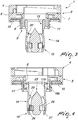
- the reference numeral 1 generally designates a anti-siphoning device, particularly for preventing the extraction of fuel from tanks 2 of vehicles of the type with a vertical or oblique connector.
- tanks 2 are positioned below the loading surface 3 of the vehicle at a preset distance H from the device 1 which is further positioned inward with respect to the overlying loading surface 3, for its better protection.
- the device 1 comprises a first ring 4, which is usually used as an interconnection element with a cap.
- this is annular and is perforated axially; it is associated, or rendered integral so as to constitute a single element, with an underlying second ring 5, which is substantially T-shaped, perforated axially and provided with a first head 6 from the perimetric rim of which a wall 7 and an axial tube 8 protrude, on the opposite side with respect to the first ring 4.
- the first ring 4 may be substituted by a cap or by a valve or by any other means adapted to close the entry port of the device 1.
- a T-shaped third ring 9 is associated with the second ring 5 and comprises thus a second head 10 which can be associated, for example by screwing or by fixing in a bayonet-like manner, internally with the wall 7, and a stem 11 which is provided externally with means for fixing to the inlet of a tank, such as for example a threading or a bayonet, and which is arranged concentrically and externally to the axial tube 8.
- the stem 11 can be externally shaped according to the desired type of tank inlet for which it will be designed.
- the third ring 9 is kept associated with the second ring 5 by way of a retaining ring or "C-clip" 12 in elastic steel.
- the set of the first ring 4, second ring 5 and third ring 9 can thus be coupled to the tank 2.
- the first end 13 of a duct 14, which protrudes with its second end 15 within the tank 2, can be arranged and associated rotatably.
- the duct 14 is substantially cylindrical and a plurality of axial slots 16, which are adapted to allow the venting of the air from the tank 2, are provided at the outer lateral surface of the first end 13.
- the pair of first and second holes 7a, 17b, 18a, 18b are mutually axially aligned so as to allow the placement of a pair of pivots 19a, 19b which allow the rotatable connection of the duct 14 to the axial tube 8.
- the duct 14 can thus oscillate with respect to the axial tube 8, as illustrated in Figure 6 , by a desired angle.
- a step 20 which constitutes an abutment for the end of the dispensing duct 21 of a nozzle 22 once it is arranged inside the device 1.
- the maximum angle of inclination entails the possibility, once the dispensing duct 21 of the nozzle 22 has been inserted in the device 1, that the dispensing duct 21 be arranged in abutment on the step 20, the duct 14 and the dispensing duct 21 remaining substantially mutually axially aligned.
- An ogive 23 is associated inside the second end 15 of the duct 14 and is adapted to guide and direct the flow of the fuel according to a fluid stream.
- the ogive 23 is provided in a downward region with means which are adapted to space the ogive 23 apart from the inner lateral surface 24 of the duct 14 and which are adapted to prevent the insertion of tubes to draw fuel; the means are constituted by a flat spring 25 which is folded in a zigzag arrangement and is then wound at an annular slot 26 which is provided in a downward region with respect to the ogive 23 and abuts against the inner lateral surface 24.
- the second end 15 of the duct 14 is detachably associable with a dome 27 for supporting and containing the spring 25.
- a gasket 28 can be associated coaxially with the stem 11 of the third ring 9.
- the invention fully achieves the intended aim and objects, a device being provided which makes it possible both to achieve an optimal and rapid dispensing of fuel and at the same time to prevent the drawing-off of fuel from the tank even in the condition where the tank is full.
Landscapes
- Engineering & Computer Science (AREA)
- Mechanical Engineering (AREA)
- Life Sciences & Earth Sciences (AREA)
- Sustainable Development (AREA)
- Sustainable Energy (AREA)
- Chemical & Material Sciences (AREA)
- Combustion & Propulsion (AREA)
- Transportation (AREA)
- Cooling, Air Intake And Gas Exhaust, And Fuel Tank Arrangements In Propulsion Units (AREA)
Claims (9)
- Dispositif anti-siphonnement (1) servant en particulier à empêcher l'extraction de carburant de réservoirs (2), le dispositif comprenant une seconde bague (5) qui est pourvue d'un tube axial (8) et à laquelle peut être associée une troisième bague (9) qui peut être couplée audit réservoir (2), la première extrémité (13) d'un conduit (14) qui fait saillie à l'intérieur du réservoir (2), lorsque qu'il est monté sur celui-ci, étant associée de façon tournante audit tube axial (8), caractérisé en ce que ledit conduit (14) est doté, axialement et à la seconde extrémité (15), d'une ogive (23) qui est adaptée à guider et diriger l'écoulement du carburant conformément à un courant de fluide, des moyens étant prévus pour espacer ladite ogive (23) de la surface latérale interne dudit conduit (14).
- Dispositif (1) suivant la revendication 1, le dispositif comprenant une première bague (4) qui est de forme annulaire, perforée axialement et associée à une seconde bague sous-jacente (5) ou rendue solidaire de celle-ci, de manière à former une seule pièce avec elle, ladite bague sous-jacente (4) étant essentiellement en forme de T, perforée axialement et pourvue d'une première tête (6), depuis le bord périmétrique de laquelle font saillie, sur le côté opposé par rapport à la première bague (4), une paroi (7) et ledit tube axial (8), une troisième bague en forme de T (9) étant associée à ladite seconde bague (5), troisième bague (9) qui comprend une seconde tête (10) qui peut être associée, à l'intérieur, à ladite paroi (7) et à une tige à filetage externe (11) qui est disposée concentriquement et à l'extérieur par rapport audit tube axial (8), caractérisé en ce que ladite première extrémité (13) d'un conduit (14), qui fait saillie avec sa seconde extrémité (15) à l'intérieur du réservoir (2), peut être disposée à l'intérieur dudit tube axial (8) et est associée de façon rotative à celui-ci.
- Dispositif (1) suivant les revendications 1 et 2, caractérisé en ce que ledit conduit (14) est essentiellement cylindrique et en ce qu'il y a, au niveau de la surface latérale extérieure de ladite première extrémité (13), une pluralité de fentes axiales (16) qui sont adaptées à permettre l'éventage de l'air du réservoir (2), qu'il y a, au niveau de la première extrémité (13), le long du même axe transversal, une paire de premiers trous (17a, 17b), et, à l'extrémité dudit tube axial (8), situées le long du même axe transversal, une paire de seconds trous (18a, 18b).
- Dispositif (1) suivant les revendications 1 et 2, caractérisé en ce qu'une fois que ledit conduit (14) a été positionné par rapport audit tube axial (8), ladite paire de premiers et seconds trous (17a, 17b, 18a, 18b) sont alignés de façon axialement les uns par rapport aux autres de sorte à permettre le placement d'une paire de pivots (19a, 19b) qui permettent le raccordement libre et tournant dudit conduit (14) audit tube axial (8).
- Dispositif (1) suivant les revendications 1 et 4, caractérisé en ce qu'à l'intérieur dudit conduit (14), il y a, entre les premières et secondes extrémités (13, 15) un épaulement (20) qui est destiné à l'appui de l'extrémité du conduit distributeur (21) d'une buse (22) une fois que celle-ci est disposée à l'intérieur dudit dispositif (1).
- Dispositif (1) suivant les revendications 1 et 5, caractérisé en ce que l'angle d'inclinaison maximal dudit conduit (14) permet, une fois que le conduit distributeur (21) de ladite buse (22) est inséré dans ledit dispositif (1), de disposer ledit conduit distributeur (21) en appui contre ledit épaulement (20), ledit conduit (14) et ledit conduit distributeur (21) restant essentiellement alignés axialement l'un par rapport à l'autre.
- Dispositif (1) suivant les revendications 1 et 2, caractérisé en ce qu'une ogive (23) est associée à l'intérieur de ladite seconde extrémité (15) dudit conduit (14) et adaptée à guider et diriger l'écoulement du carburant conformément à un courant de fluide, la section transversale de ladite surface latérale interne de ladite seconde extrémité (15) étant légèrement courbée.
- Dispositif (1) suivant les revendications 1 à 7, caractérisé en ce que ladite ogive (23) est prévue dans une zone inférieure avec des moyens qui sont adaptés à l'espacer de la surface latérale interne (24) dudit conduit (14) et à empêcher l'insertion de tubes pour aspirer du carburant, lesdits moyens étant constitués par un ressort plat (25) qui est plié en zigzag, puis enroulé au niveau d'une fente annulaire (26) qui est prévue dans une zone inférieure par rapport à ladite ogive (23) et qui s'appuie contre ladite surface latérale interne (24).
- Dispositif (1) suivant les revendications 1 et 8, caractérisé en ce qu'un dôme porteur et de confinement (27) pour ledit ressort (25) peut être associé de façon amovible à ladite seconde extrémité (15) dudit conduit (14) et en ce qu'un joint (28) peut être associé coaxialement à ladite tige (11) de ladite troisième bague (9).
Priority Applications (1)
| Application Number | Priority Date | Filing Date | Title |
|---|---|---|---|
| PL15733732T PL3164287T3 (pl) | 2014-07-04 | 2015-07-01 | Urządzenie zapobiegające syfonowaniu, zwłaszcza zapobiegające ekstrakcji paliwa ze zbiorników |
Applications Claiming Priority (2)
| Application Number | Priority Date | Filing Date | Title |
|---|---|---|---|
| ITTV20140097 | 2014-07-04 | ||
| PCT/EP2015/065039 WO2016001330A1 (fr) | 2014-07-04 | 2015-07-01 | Dispositif anti-siphonage, en particulier pour empêcher l'extraction de carburant à partir de réservoirs |
Publications (2)
| Publication Number | Publication Date |
|---|---|
| EP3164287A1 EP3164287A1 (fr) | 2017-05-10 |
| EP3164287B1 true EP3164287B1 (fr) | 2018-08-01 |
Family
ID=51655928
Family Applications (1)
| Application Number | Title | Priority Date | Filing Date |
|---|---|---|---|
| EP15733732.0A Active EP3164287B1 (fr) | 2014-07-04 | 2015-07-01 | Dispositif anti-siphonage, en particulier pour empêcher l'extraction de carburant à partir de réservoirs |
Country Status (8)
| Country | Link |
|---|---|
| US (1) | US10266049B2 (fr) |
| EP (1) | EP3164287B1 (fr) |
| CN (1) | CN106687324B (fr) |
| BR (1) | BR112016029962A2 (fr) |
| CA (1) | CA2951988C (fr) |
| ES (1) | ES2695123T3 (fr) |
| PL (1) | PL3164287T3 (fr) |
| WO (1) | WO2016001330A1 (fr) |
Families Citing this family (1)
| Publication number | Priority date | Publication date | Assignee | Title |
|---|---|---|---|---|
| WO2020000113A1 (fr) * | 2018-06-27 | 2020-01-02 | DAVANZO CARAM, Juan Sebastián | Dispositif destiné à empêcher le siphonnage de carburant à partir des réservoirs présents sur tous les types de véhicules |
Family Cites Families (11)
| Publication number | Priority date | Publication date | Assignee | Title |
|---|---|---|---|---|
| US3951297A (en) * | 1974-05-06 | 1976-04-20 | Carlos A. Riquelme | Anti-siphon gas tank adaptor |
| FR2852893B3 (fr) * | 2003-03-24 | 2005-03-18 | Michel Czurylo | Dispositif anti-siphonnage gasoil poids lourds et utilaires pour tube de remplissage coude de reservoir |
| FR2877277B1 (fr) * | 2004-10-29 | 2008-07-04 | Thierry Fourment | Dispositif anti-siphonnage pour reservoir de carburant emboutie par sa forme |
| AU2006226744B2 (en) * | 2005-03-23 | 2012-02-23 | Velocys, Inc. | Surface features in microprocess technology |
| PL2004441T3 (pl) * | 2006-03-28 | 2012-06-29 | Tiss Ltd | Wlot do zbiornika zapobiegający efektowi syfonowymi |
| GB0606126D0 (en) * | 2006-03-28 | 2006-05-03 | Tiss Ltd | Anti siphon tank inlet |
| US7721902B2 (en) * | 2006-06-27 | 2010-05-25 | Neffco Tech, Llc | Fuel anti-siphon device |
| GB0806811D0 (en) * | 2008-04-15 | 2008-05-14 | Tiss Ltd | Anti siphon tank inlet |
| IT1391204B1 (it) | 2008-09-22 | 2011-11-18 | Lago Accessori S R L | Dispositivo antifurto, particolarmente per impedire la estrazione di carburante da serbatoi |
| GB2476954A (en) * | 2010-01-14 | 2011-07-20 | Tiss Ltd | Anti siphon device |
| DE102012016084A1 (de) * | 2012-08-14 | 2014-05-15 | Illinois Tool Works Inc. | Führungseinrichtung für eine Kraftstoffzapfpistole |
-
2015
- 2015-07-01 CA CA2951988A patent/CA2951988C/fr active Active
- 2015-07-01 PL PL15733732T patent/PL3164287T3/pl unknown
- 2015-07-01 CN CN201580036353.XA patent/CN106687324B/zh active Active
- 2015-07-01 WO PCT/EP2015/065039 patent/WO2016001330A1/fr not_active Ceased
- 2015-07-01 US US15/323,909 patent/US10266049B2/en active Active
- 2015-07-01 EP EP15733732.0A patent/EP3164287B1/fr active Active
- 2015-07-01 BR BR112016029962A patent/BR112016029962A2/pt not_active Application Discontinuation
- 2015-07-01 ES ES15733732T patent/ES2695123T3/es active Active
Also Published As
| Publication number | Publication date |
|---|---|
| US20170151868A1 (en) | 2017-06-01 |
| US10266049B2 (en) | 2019-04-23 |
| EP3164287A1 (fr) | 2017-05-10 |
| CN106687324A (zh) | 2017-05-17 |
| BR112016029962A2 (pt) | 2017-08-22 |
| WO2016001330A1 (fr) | 2016-01-07 |
| PL3164287T3 (pl) | 2019-02-28 |
| CN106687324B (zh) | 2019-01-18 |
| ES2695123T3 (es) | 2019-01-02 |
| CA2951988C (fr) | 2022-06-21 |
| CA2951988A1 (fr) | 2016-01-07 |
Similar Documents
| Publication | Publication Date | Title |
|---|---|---|
| EP2004441B1 (fr) | Orifice d'entrée de réservoir antisiphon | |
| EP2523818B1 (fr) | Dispositif antisiphon | |
| EP2429849B1 (fr) | Dispositif anti-siphonage | |
| EP2165873B1 (fr) | Dispositif antivol, en particulier pour prévenir le soutirage de carburant de réservoirs | |
| EP3164287B1 (fr) | Dispositif anti-siphonage, en particulier pour empêcher l'extraction de carburant à partir de réservoirs | |
| EP3164288B1 (fr) | Dispositif de prévention d'enlèvement pour dispositifs anti-siphons pour réservoirs | |
| GB2382568A (en) | Fill tube for fuel storage tanks | |
| EP3590884B1 (fr) | Pistolet de ravitaillement en carburant | |
| GB2406333A (en) | Anti-siphon tank inlet | |
| EP1852297B1 (fr) | Goulotte de remplissage d'essence pour véhicule automobile | |
| EP3823858B1 (fr) | Dispositif de remplissage de réservoir | |
| US11938808B2 (en) | Obstruction design | |
| US5799710A (en) | Arrangement in connection with an anaesthetic liquid container | |
| WO2001007322A1 (fr) | Adaptateur pour ouverture de recipient | |
| WO2020000113A1 (fr) | Dispositif destiné à empêcher le siphonnage de carburant à partir des réservoirs présents sur tous les types de véhicules |
Legal Events
| Date | Code | Title | Description |
|---|---|---|---|
| STAA | Information on the status of an ep patent application or granted ep patent |
Free format text: STATUS: THE INTERNATIONAL PUBLICATION HAS BEEN MADE |
|
| PUAI | Public reference made under article 153(3) epc to a published international application that has entered the european phase |
Free format text: ORIGINAL CODE: 0009012 |
|
| STAA | Information on the status of an ep patent application or granted ep patent |
Free format text: STATUS: REQUEST FOR EXAMINATION WAS MADE |
|
| 17P | Request for examination filed |
Effective date: 20170202 |
|
| AK | Designated contracting states |
Kind code of ref document: A1 Designated state(s): AL AT BE BG CH CY CZ DE DK EE ES FI FR GB GR HR HU IE IS IT LI LT LU LV MC MK MT NL NO PL PT RO RS SE SI SK SM TR |
|
| AX | Request for extension of the european patent |
Extension state: BA ME |
|
| DAV | Request for validation of the european patent (deleted) | ||
| DAX | Request for extension of the european patent (deleted) | ||
| GRAP | Despatch of communication of intention to grant a patent |
Free format text: ORIGINAL CODE: EPIDOSNIGR1 |
|
| STAA | Information on the status of an ep patent application or granted ep patent |
Free format text: STATUS: GRANT OF PATENT IS INTENDED |
|
| INTG | Intention to grant announced |
Effective date: 20180215 |
|
| GRAS | Grant fee paid |
Free format text: ORIGINAL CODE: EPIDOSNIGR3 |
|
| GRAA | (expected) grant |
Free format text: ORIGINAL CODE: 0009210 |
|
| STAA | Information on the status of an ep patent application or granted ep patent |
Free format text: STATUS: THE PATENT HAS BEEN GRANTED |
|
| AK | Designated contracting states |
Kind code of ref document: B1 Designated state(s): AL AT BE BG CH CY CZ DE DK EE ES FI FR GB GR HR HU IE IS IT LI LT LU LV MC MK MT NL NO PL PT RO RS SE SI SK SM TR |
|
| REG | Reference to a national code |
Ref country code: GB Ref legal event code: FG4D |
|
| REG | Reference to a national code |
Ref country code: CH Ref legal event code: EP Ref country code: AT Ref legal event code: REF Ref document number: 1023886 Country of ref document: AT Kind code of ref document: T Effective date: 20180815 |
|
| REG | Reference to a national code |
Ref country code: IE Ref legal event code: FG4D |
|
| REG | Reference to a national code |
Ref country code: DE Ref legal event code: R096 Ref document number: 602015014343 Country of ref document: DE |
|
| REG | Reference to a national code |
Ref country code: NL Ref legal event code: FP |
|
| REG | Reference to a national code |
Ref country code: LT Ref legal event code: MG4D |
|
| REG | Reference to a national code |
Ref country code: ES Ref legal event code: FG2A Ref document number: 2695123 Country of ref document: ES Kind code of ref document: T3 Effective date: 20190102 |
|
| REG | Reference to a national code |
Ref country code: AT Ref legal event code: MK05 Ref document number: 1023886 Country of ref document: AT Kind code of ref document: T Effective date: 20180801 |
|
| PG25 | Lapsed in a contracting state [announced via postgrant information from national office to epo] |
Ref country code: FI Free format text: LAPSE BECAUSE OF FAILURE TO SUBMIT A TRANSLATION OF THE DESCRIPTION OR TO PAY THE FEE WITHIN THE PRESCRIBED TIME-LIMIT Effective date: 20180801 Ref country code: RS Free format text: LAPSE BECAUSE OF FAILURE TO SUBMIT A TRANSLATION OF THE DESCRIPTION OR TO PAY THE FEE WITHIN THE PRESCRIBED TIME-LIMIT Effective date: 20180801 Ref country code: SE Free format text: LAPSE BECAUSE OF FAILURE TO SUBMIT A TRANSLATION OF THE DESCRIPTION OR TO PAY THE FEE WITHIN THE PRESCRIBED TIME-LIMIT Effective date: 20180801 Ref country code: GR Free format text: LAPSE BECAUSE OF FAILURE TO SUBMIT A TRANSLATION OF THE DESCRIPTION OR TO PAY THE FEE WITHIN THE PRESCRIBED TIME-LIMIT Effective date: 20181102 Ref country code: AT Free format text: LAPSE BECAUSE OF FAILURE TO SUBMIT A TRANSLATION OF THE DESCRIPTION OR TO PAY THE FEE WITHIN THE PRESCRIBED TIME-LIMIT Effective date: 20180801 Ref country code: NO Free format text: LAPSE BECAUSE OF FAILURE TO SUBMIT A TRANSLATION OF THE DESCRIPTION OR TO PAY THE FEE WITHIN THE PRESCRIBED TIME-LIMIT Effective date: 20181101 Ref country code: LT Free format text: LAPSE BECAUSE OF FAILURE TO SUBMIT A TRANSLATION OF THE DESCRIPTION OR TO PAY THE FEE WITHIN THE PRESCRIBED TIME-LIMIT Effective date: 20180801 Ref country code: IS Free format text: LAPSE BECAUSE OF FAILURE TO SUBMIT A TRANSLATION OF THE DESCRIPTION OR TO PAY THE FEE WITHIN THE PRESCRIBED TIME-LIMIT Effective date: 20181201 Ref country code: BG Free format text: LAPSE BECAUSE OF FAILURE TO SUBMIT A TRANSLATION OF THE DESCRIPTION OR TO PAY THE FEE WITHIN THE PRESCRIBED TIME-LIMIT Effective date: 20181101 |
|
| PG25 | Lapsed in a contracting state [announced via postgrant information from national office to epo] |
Ref country code: HR Free format text: LAPSE BECAUSE OF FAILURE TO SUBMIT A TRANSLATION OF THE DESCRIPTION OR TO PAY THE FEE WITHIN THE PRESCRIBED TIME-LIMIT Effective date: 20180801 Ref country code: LV Free format text: LAPSE BECAUSE OF FAILURE TO SUBMIT A TRANSLATION OF THE DESCRIPTION OR TO PAY THE FEE WITHIN THE PRESCRIBED TIME-LIMIT Effective date: 20180801 Ref country code: AL Free format text: LAPSE BECAUSE OF FAILURE TO SUBMIT A TRANSLATION OF THE DESCRIPTION OR TO PAY THE FEE WITHIN THE PRESCRIBED TIME-LIMIT Effective date: 20180801 |
|
| PG25 | Lapsed in a contracting state [announced via postgrant information from national office to epo] |
Ref country code: RO Free format text: LAPSE BECAUSE OF FAILURE TO SUBMIT A TRANSLATION OF THE DESCRIPTION OR TO PAY THE FEE WITHIN THE PRESCRIBED TIME-LIMIT Effective date: 20180801 Ref country code: CZ Free format text: LAPSE BECAUSE OF FAILURE TO SUBMIT A TRANSLATION OF THE DESCRIPTION OR TO PAY THE FEE WITHIN THE PRESCRIBED TIME-LIMIT Effective date: 20180801 Ref country code: EE Free format text: LAPSE BECAUSE OF FAILURE TO SUBMIT A TRANSLATION OF THE DESCRIPTION OR TO PAY THE FEE WITHIN THE PRESCRIBED TIME-LIMIT Effective date: 20180801 |
|
| REG | Reference to a national code |
Ref country code: DE Ref legal event code: R097 Ref document number: 602015014343 Country of ref document: DE |
|
| PG25 | Lapsed in a contracting state [announced via postgrant information from national office to epo] |
Ref country code: DK Free format text: LAPSE BECAUSE OF FAILURE TO SUBMIT A TRANSLATION OF THE DESCRIPTION OR TO PAY THE FEE WITHIN THE PRESCRIBED TIME-LIMIT Effective date: 20180801 Ref country code: SK Free format text: LAPSE BECAUSE OF FAILURE TO SUBMIT A TRANSLATION OF THE DESCRIPTION OR TO PAY THE FEE WITHIN THE PRESCRIBED TIME-LIMIT Effective date: 20180801 Ref country code: SM Free format text: LAPSE BECAUSE OF FAILURE TO SUBMIT A TRANSLATION OF THE DESCRIPTION OR TO PAY THE FEE WITHIN THE PRESCRIBED TIME-LIMIT Effective date: 20180801 |
|
| PLBE | No opposition filed within time limit |
Free format text: ORIGINAL CODE: 0009261 |
|
| STAA | Information on the status of an ep patent application or granted ep patent |
Free format text: STATUS: NO OPPOSITION FILED WITHIN TIME LIMIT |
|
| 26N | No opposition filed |
Effective date: 20190503 |
|
| PG25 | Lapsed in a contracting state [announced via postgrant information from national office to epo] |
Ref country code: SI Free format text: LAPSE BECAUSE OF FAILURE TO SUBMIT A TRANSLATION OF THE DESCRIPTION OR TO PAY THE FEE WITHIN THE PRESCRIBED TIME-LIMIT Effective date: 20180801 |
|
| PG25 | Lapsed in a contracting state [announced via postgrant information from national office to epo] |
Ref country code: MC Free format text: LAPSE BECAUSE OF FAILURE TO SUBMIT A TRANSLATION OF THE DESCRIPTION OR TO PAY THE FEE WITHIN THE PRESCRIBED TIME-LIMIT Effective date: 20180801 |
|
| REG | Reference to a national code |
Ref country code: CH Ref legal event code: PL |
|
| PG25 | Lapsed in a contracting state [announced via postgrant information from national office to epo] |
Ref country code: TR Free format text: LAPSE BECAUSE OF FAILURE TO SUBMIT A TRANSLATION OF THE DESCRIPTION OR TO PAY THE FEE WITHIN THE PRESCRIBED TIME-LIMIT Effective date: 20180801 |
|
| REG | Reference to a national code |
Ref country code: BE Ref legal event code: MM Effective date: 20190731 |
|
| PG25 | Lapsed in a contracting state [announced via postgrant information from national office to epo] |
Ref country code: LU Free format text: LAPSE BECAUSE OF NON-PAYMENT OF DUE FEES Effective date: 20190701 Ref country code: LI Free format text: LAPSE BECAUSE OF NON-PAYMENT OF DUE FEES Effective date: 20190731 Ref country code: CH Free format text: LAPSE BECAUSE OF NON-PAYMENT OF DUE FEES Effective date: 20190731 Ref country code: BE Free format text: LAPSE BECAUSE OF NON-PAYMENT OF DUE FEES Effective date: 20190731 |
|
| PG25 | Lapsed in a contracting state [announced via postgrant information from national office to epo] |
Ref country code: PT Free format text: LAPSE BECAUSE OF FAILURE TO SUBMIT A TRANSLATION OF THE DESCRIPTION OR TO PAY THE FEE WITHIN THE PRESCRIBED TIME-LIMIT Effective date: 20181201 |
|
| PG25 | Lapsed in a contracting state [announced via postgrant information from national office to epo] |
Ref country code: IE Free format text: LAPSE BECAUSE OF NON-PAYMENT OF DUE FEES Effective date: 20190701 |
|
| PG25 | Lapsed in a contracting state [announced via postgrant information from national office to epo] |
Ref country code: CY Free format text: LAPSE BECAUSE OF FAILURE TO SUBMIT A TRANSLATION OF THE DESCRIPTION OR TO PAY THE FEE WITHIN THE PRESCRIBED TIME-LIMIT Effective date: 20180801 |
|
| PG25 | Lapsed in a contracting state [announced via postgrant information from national office to epo] |
Ref country code: HU Free format text: LAPSE BECAUSE OF FAILURE TO SUBMIT A TRANSLATION OF THE DESCRIPTION OR TO PAY THE FEE WITHIN THE PRESCRIBED TIME-LIMIT; INVALID AB INITIO Effective date: 20150701 Ref country code: MT Free format text: LAPSE BECAUSE OF FAILURE TO SUBMIT A TRANSLATION OF THE DESCRIPTION OR TO PAY THE FEE WITHIN THE PRESCRIBED TIME-LIMIT Effective date: 20180801 |
|
| PG25 | Lapsed in a contracting state [announced via postgrant information from national office to epo] |
Ref country code: MK Free format text: LAPSE BECAUSE OF FAILURE TO SUBMIT A TRANSLATION OF THE DESCRIPTION OR TO PAY THE FEE WITHIN THE PRESCRIBED TIME-LIMIT Effective date: 20180801 |
|
| REG | Reference to a national code |
Ref country code: DE Ref legal event code: R082 Ref document number: 602015014343 Country of ref document: DE Representative=s name: SCHIEBER - FARAGO PATENTANWAELTE, DE Ref country code: DE Ref legal event code: R082 Ref document number: 602015014343 Country of ref document: DE Representative=s name: FARAGO PATENTANWALTSGESELLSCHAFT MBH, DE |
|
| REG | Reference to a national code |
Ref country code: DE Ref legal event code: R082 Ref document number: 602015014343 Country of ref document: DE Representative=s name: SCHIEBER - FARAGO PATENTANWAELTE, DE |
|
| P01 | Opt-out of the competence of the unified patent court (upc) registered |
Effective date: 20230528 |
|
| PGFP | Annual fee paid to national office [announced via postgrant information from national office to epo] |
Ref country code: DE Payment date: 20240617 Year of fee payment: 10 |
|
| PGFP | Annual fee paid to national office [announced via postgrant information from national office to epo] |
Ref country code: GB Payment date: 20240719 Year of fee payment: 10 |
|
| PGFP | Annual fee paid to national office [announced via postgrant information from national office to epo] |
Ref country code: FR Payment date: 20240711 Year of fee payment: 10 |
|
| PGFP | Annual fee paid to national office [announced via postgrant information from national office to epo] |
Ref country code: PL Payment date: 20250623 Year of fee payment: 11 |
|
| PGFP | Annual fee paid to national office [announced via postgrant information from national office to epo] |
Ref country code: NL Payment date: 20250714 Year of fee payment: 11 |
|
| PGFP | Annual fee paid to national office [announced via postgrant information from national office to epo] |
Ref country code: ES Payment date: 20250805 Year of fee payment: 11 |
|
| PGFP | Annual fee paid to national office [announced via postgrant information from national office to epo] |
Ref country code: IT Payment date: 20250620 Year of fee payment: 11 |
|
| REG | Reference to a national code |
Ref country code: DE Ref legal event code: R119 Ref document number: 602015014343 Country of ref document: DE |
|
| GBPC | Gb: european patent ceased through non-payment of renewal fee |
Effective date: 20250701 |
|
| PG25 | Lapsed in a contracting state [announced via postgrant information from national office to epo] |
Ref country code: GB Free format text: LAPSE BECAUSE OF NON-PAYMENT OF DUE FEES Effective date: 20250701 |
|
| PG25 | Lapsed in a contracting state [announced via postgrant information from national office to epo] |
Ref country code: DE Free format text: LAPSE BECAUSE OF NON-PAYMENT OF DUE FEES Effective date: 20260203 |
|
| PG25 | Lapsed in a contracting state [announced via postgrant information from national office to epo] |
Ref country code: FR Free format text: LAPSE BECAUSE OF NON-PAYMENT OF DUE FEES Effective date: 20250731 |