EP3164657B1 - Energiespeichereinrichtung zur zwischenspeicherung von thermischer energie, kraftwerk mit einer energiespeichereinrichtung sowie verfahren zum betreiben einer energiespeichereinrichtung - Google Patents
Energiespeichereinrichtung zur zwischenspeicherung von thermischer energie, kraftwerk mit einer energiespeichereinrichtung sowie verfahren zum betreiben einer energiespeichereinrichtung Download PDFInfo
- Publication number
- EP3164657B1 EP3164657B1 EP15730467.6A EP15730467A EP3164657B1 EP 3164657 B1 EP3164657 B1 EP 3164657B1 EP 15730467 A EP15730467 A EP 15730467A EP 3164657 B1 EP3164657 B1 EP 3164657B1
- Authority
- EP
- European Patent Office
- Prior art keywords
- fluid
- storage chamber
- storage device
- heat
- storage
- Prior art date
- Legal status (The legal status is an assumption and is not a legal conclusion. Google has not performed a legal analysis and makes no representation as to the accuracy of the status listed.)
- Active
Links
Images

Classifications
-
- F—MECHANICAL ENGINEERING; LIGHTING; HEATING; WEAPONS; BLASTING
- F28—HEAT EXCHANGE IN GENERAL
- F28D—HEAT-EXCHANGE APPARATUS, NOT PROVIDED FOR IN ANOTHER SUBCLASS, IN WHICH THE HEAT-EXCHANGE MEDIA DO NOT COME INTO DIRECT CONTACT
- F28D20/00—Heat storage plants or apparatus in general; Regenerative heat-exchange apparatus not covered by groups F28D17/00 or F28D19/00
- F28D20/0034—Heat storage plants or apparatus in general; Regenerative heat-exchange apparatus not covered by groups F28D17/00 or F28D19/00 using liquid heat storage material
- F28D20/0039—Heat storage plants or apparatus in general; Regenerative heat-exchange apparatus not covered by groups F28D17/00 or F28D19/00 using liquid heat storage material with stratification of the heat storage material
-
- F—MECHANICAL ENGINEERING; LIGHTING; HEATING; WEAPONS; BLASTING
- F28—HEAT EXCHANGE IN GENERAL
- F28D—HEAT-EXCHANGE APPARATUS, NOT PROVIDED FOR IN ANOTHER SUBCLASS, IN WHICH THE HEAT-EXCHANGE MEDIA DO NOT COME INTO DIRECT CONTACT
- F28D20/00—Heat storage plants or apparatus in general; Regenerative heat-exchange apparatus not covered by groups F28D17/00 or F28D19/00
- F28D2020/0065—Details, e.g. particular heat storage tanks, auxiliary members within tanks
- F28D2020/0086—Partitions
- F28D2020/0095—Partitions movable or floating
-
- Y—GENERAL TAGGING OF NEW TECHNOLOGICAL DEVELOPMENTS; GENERAL TAGGING OF CROSS-SECTIONAL TECHNOLOGIES SPANNING OVER SEVERAL SECTIONS OF THE IPC; TECHNICAL SUBJECTS COVERED BY FORMER USPC CROSS-REFERENCE ART COLLECTIONS [XRACs] AND DIGESTS
- Y02—TECHNOLOGIES OR APPLICATIONS FOR MITIGATION OR ADAPTATION AGAINST CLIMATE CHANGE
- Y02E—REDUCTION OF GREENHOUSE GAS [GHG] EMISSIONS, RELATED TO ENERGY GENERATION, TRANSMISSION OR DISTRIBUTION
- Y02E60/00—Enabling technologies; Technologies with a potential or indirect contribution to GHG emissions mitigation
- Y02E60/14—Thermal energy storage
Definitions
- the invention relates to an energy storage device for temporary storage of thermal energy. Furthermore, it relates to a power plant, in particular a solar power plant, wind power plant or solar thermal wind power plant, with at least one energy storage device and a method for operating an energy storage device.
- the input called energy storage device can be used in a variety of applications application to cache thermal energy, so for example to load during a first period of thermal energy and to discharge during a second period following this first period. With the aid of the energy storage device, energy is thus absorbed during the first period which is made available by a heat source. During the second period, the cached thermal energy is removed again, for example, to supply it to a heat consumer.
- the energy storage device is provided to temporarily store only periodically available thermal energy to be released again when the thermal energy is currently not available.
- the energy storage device is part of a power plant, preferably a power plant for generating electricity from renewable energy.
- the power plant may thus be, for example, a solar power plant, a wind power plant or a combined power plant.
- the latter is to be understood in particular a solar thermal wind power plant.
- This has means for generating electrical energy and / or thermal energy from a plurality of regenerative energy sources, preferably both from solar power and from wind power. In this case, preferably that regenerative energy source is used, from which momentarily energy can be provided.
- a closed storage circuit is provided to which heat can be supplied by means of a heat source, and by means of a heat consumer and in which a fluid container is present, which is divided by means of a displaceable separating element into a first fluid storage chamber for colder fluid and a second fluid storage chamber for warmer fluid in which at least one pump is provided in the storage circuit, by means of which fluid from the first fluid storage chamber in the second fluid storage chamber and / or vice versa is conveyed, and that the fluid container is present as a pipeline with horizontally arranged and at least partially curved longitudinal central axis and a ratio between length and Width of at least 5 has.
- the fluid is present, which can be promoted by means of the pump and also referred to as storage fluid.
- the fluid container is provided. This preferably has a volume which is designed for temporary storage of the desired amount of energy or amount of heat.
- the storage circuit is preferably associated with the heat source and the heat consumer. With the help of the heat source, thermal energy, ie heat, can be introduced into the storage circuit. In contrast, the heat consumer serves to remove thermal energy or heat from the storage circuit.
- the heat source and the heat consumer may be separate devices. However, it can also be provided that the heat source and the heat consumer of one and the same device, such as a heat exchanger or the like, are formed.
- the separating element is arranged, which divides the fluid container into the first fluid storage chamber and the second fluid storage chamber.
- the separating element is displaceable such that both the first fluid storage chamber and the second fluid storage chamber each have a variable volume.
- the fluid container per se has a total volume, which results from the sum of the volume of the first fluid storage chamber and the volume of the second fluid storage chamber.
- the first fluid storage chamber is provided for colder fluid, the second fluid storage chamber for warmer fluid, or vice versa.
- fluid is discharged from the second fluid storage chamber.
- This fluid is then cooled using the heat consumer, so brought to a lower temperature level.
- the cooled and thus colder fluid is supplied to the first fluid storage chamber.
- the separating element is displaced in such a way that the first fluid storage chamber becomes larger, but the second fluid storage chamber is smaller. The enlargement of the first fluid storage chamber or the reduction of the second fluid storage chamber takes place in each case by the volume of the removed warmer fluid or the supplied cooled fluid.
- the at least one pump is provided. This is present in the closed storage circuit, preferably outside the fluid container. Alternatively, it may of course also be integrated in these.
- the fluid container can basically have any shape. Particularly preferably, it has a circular cross-section along its longitudinal central axis.
- the longitudinal central axis runs straight, so that the fluid container is so far in the form of a cylinder, in particular a circular cylinder present.
- the longitudinal central axis is curved at least in regions, so that the fluid container has, for example, a U-shape or an O-shape. In the latter case, the fluid container is thus annular or oval.
- end faces of the fluid container can be arranged directly adjacent to one another or at a distance from one another.
- a double U-shape of the fluid container or a stadium shape of the fluid container can also be realized.
- two U-shaped sections of the fluid container are arranged opposite each other, so that the free legs of the sections protrude toward each other or opposite each other, in particular aligned with each other.
- At least one pair of opposing legs can be fluidly connected to each other, this is preferably the case for each opposite leg.
- the fluid container is stadium-shaped and has two sections with mutually parallel and straight longitudinal central axes. These straight sections are connected at their ends nearest to each other via sections of the fluid container, which have curved longitudinal central axes, in particular part-circular, for example, are semicircular. Preferably, the straight sections are the same length. This may additionally or alternatively also be the case for the curved sections.
- the double U-shape it may be provided that only two of the legs of the sections are in fluid communication with each other stand while the other two legs are flow separated.
- end faces of the flow-separated legs may be arranged directly adjacent or spaced from each other.
- one of the straight sections may be interrupted so that the two end faces are also present here.
- the fluid container is present as an annular chamber, in particular as a circular ring chamber.
- a plurality of separating elements in particular at least two separating elements, are preferably arranged in the fluid container in order to completely separate the first fluid storage chamber from the second fluid storage chamber in terms of fluid technology.
- the fluid container on a continuous, so not interrupted longitudinal central axis.
- at least one of the separating elements arranged in the fluid container can be displaced, in particular several or all of the several separating elements are arranged displaceably in the fluid container.
- at least one of the separating elements is arranged stationarily in the fluid container or at least temporarily fixed by means of a suitable device in the fluid container.
- a separating element is arranged, for example, in each of the U-shaped sections, wherein at least one of the separating elements, in particular all separating elements are displaced.
- the separating elements are arranged such that they are displaced only in that subsection to which they are assigned. It is so far at least an end stop is provided, which prevents the crossing of the separating elements from the portion to which they are assigned, in the respective other portion.
- the separating elements are displaceable only in the straight sections and a crossing into the curved sections is respectively prevented, for example by means of at least one end stop.
- the arrangement of the longitudinal center axis is basically arbitrary. According to the invention, it is arranged horizontally, ie in particular parallel or at least partially parallel to a substrate, on or below which the energy storage device is arranged.
- the longitudinal center axis of the fluid container can be arranged at any angle with respect to the ground, in particular an angle of at least 0 ° and at most 90 °. This means that the fluid container or its longitudinal central axis can be arranged or aligned vertically. In this case, the longitudinal central axis is perpendicular to the ground.
- the vertical arrangement of the fluid container or the corresponding alignment of its longitudinal center axis allows a particularly reliable guidance and / or storage of the separating element.
- the fluid can be chosen arbitrarily. However, it preferably has a high heat capacity.
- water is used as the fluid.
- At least one additive can be added to the water be, for example, ethylene glycol or the like.
- the fluid is present in the fluid container at a pressure which is less than the critical pressure. Additionally or alternatively, the temperature of the fluid in the storage circuit is always less than the critical temperature of the fluid.
- the pressure of the fluid is preferably greater than an ambient pressure and may for example be at least 10 bar, at least 25 bar, at least 50 bar, at least 75 bar or at least 100 bar. For example, based on the critical pressure of the fluid, the pressure of the fluid may be at least 25%, at least 50%, at least 75%, or at least 90%.
- the fluid container is insofar as a fluid pressure vessel before.
- the maximum temperature of the fluid in the second fluid storage chamber can be at least 100 ° C., at least 150 ° C., at least 200 ° C., at least 250 ° C. or at least 300 ° C., in particular when the heat storage device is charged.
- the temperature of the fluid in the second fluid storage chamber is adjusted, in particular controlled and / or regulated so that it does not exceed the maximum temperature.
- the maximum temperature is particularly preferably chosen such that it is liquid at the pressure under which it is present in the storage cycle, even at the maximum temperature, so not evaporated. For example, based on the critical temperature of the fluid, the maximum temperature is at least 50%, at least 75%, at least 80%, at least 85%, at least 90%, or at least 95%.
- the proposed energy storage device has the advantage that it has an extremely low space requirement, but at the same time a strict separation between colder fluid and warmer fluid allows. It is therefore not, as is often the case, taken from a storage container fluid, which is subsequently warmed up and fed again to the storage container. Although the thermal energy can also be stored in such a procedure, the temperature of the fluid present in the storage container increases only comparatively slowly during heating by means of the heat source.
- the fluid in the storage container can not be brought to its maximum temperature.
- this also means that even the heat consumer only fluid can be supplied with a relatively low temperature.
- typical heat consumers for example a heat exchanger or even a steam turbine, work all the more efficiently, the higher the temperature of the fluid supplied to it or a temperature difference to a lower temperature level.
- the energy storage device by removing the colder fluid from the first fluid storage chamber, heating it and then supplying it to the second fluid storage chamber so that the latter always has fluid at almost the temperature to which it was previously applied by means of the heat source. So there is no mixing with the colder fluid instead. Consequently, the heat consumer is always fluid with the higher temperature available. It is therefore particularly preferably additionally provided that the fluid container is thermally insulated from its external environment, So has a heat insulation, which preferably surrounds him completely.
- the energy storage device described enables extremely efficient and cost-effective buffering of thermal energy. Due to the substantially constant temperature of the fluid in the second fluid storage chamber, the available enthalpy also remains substantially constant. Thus, a high specific storage capacity - based on the volume of the fluid container - achieved, which in turn leads to low cost of the energy storage device, based on the capacity in kWh.
- the power storage device need not be supplied with external heat to ensure reliable operation. In that regard, it works completely climate-neutral, especially without release of carbon dioxide.
- the energy storage device is assigned to the power station, which is designed as a wind power plant or as a combined power plant, means may be provided for converting the electrical energy generated by wind power into heat, which is subsequently stored temporarily in the energy storage device.
- the fluid container is present as a pipeline and the separating element as a pig or as a cutting disc.
- the pipeline preferably has the circular cross-section already described above with respect to its longitudinal central axis, although the latter may have an arbitrary course.
- the longitudinal central axis is straight or at least partially curved, so that the pipeline has the likewise already explained U-shape or O-shape.
- the fluid container has a volume of at least 10%, at least 20%, at least 30%, at least 40%, at least 50%, at least 60%, at least 70%, at least 75%, at least 80%, at least 90% or at least 95% of the total volume of the closed storage circuit corresponds. It is therefore particularly preferable for a larger volume of fluid to be present in the fluid container than in other areas of the storage circuit.
- the fluid container so both the first fluid storage chamber and the second fluid storage chamber is always at least mostly, ie at least 50%, at least 60%, at least 70%, at least 80%, at least 90% or at least 95%, or completely filled with fluid.
- the fluid container as a pipe, it is preferably also provided that a certain ratio between length and width of the fluid container is present.
- the length of the fluid container is to be understood to mean its extent in the direction of the longitudinal center axis, while the width describes the dimensions of the fluid container perpendicular to the longitudinal central axis.
- the fluid container is round in cross section with respect to the longitudinal central axis.
- the width corresponds to the diameter of the fluid container.
- the width or the diameter along the longitudinal central axis, in particular over the entire length of the fluid container is preferably constant or at least almost constant.
- the fluid container is significantly longer than it is wide.
- the ratio between length and width or between length and diameter is at least 5, at least 10, at least 15, at least 20 or at least 25.
- the fluid container can also be significantly longer than results from the above conditions.
- the fluid container is in the manner of a pipeline, ie as a long pipeline, which has a ratio between length and width or diameter of at least 50, at least 75 or at least 100.
- the length of each of the straight sections is preferably greater than the length of each of the curved sections.
- the ratio between the length of the straight sections and the length of the curved sections is at least 2, at least 2.5, at least 5, at least 7.5 or at least 10.
- the separating element can be designed as a pig. Newts are commonly used as cleaning or inspection equipment for pipelines, especially gas or petroleum pipelines.
- the pig in particular fills the entire cross section of the fluid container, and thus separates the first fluid storage chamber from the second fluid storage chamber.
- the pig is designed for a complete or at least almost complete seal between the two fluid storage chambers. The newt is so far as separating pig.
- the separating element can also be designed as a separating disk.
- the cutting disk has two mutually parallel surfaces, wherein one of the surfaces of the first fluid storage chamber and a second of the surfaces of the second fluid storage chamber faces.
- the cutting disk is designed in such a way the first surface seals the first fluid storage chamber and the second surface substantially seals the second fluid storage chamber.
- the fluid storage chambers facing sides or end faces of the pig may be curved or rounded, ie the surfaces which may be present as end faces of the cutting disc, arranged parallel to each other.
- the cutting disk is so far preferably in the form of a cylinder, in particular a circular cylinder before.
- the displacement of the separating element or the pig in the fluid container is preferably effected by means of fluid pressure, which is generated by the pump.
- the separating element has a drive device or the like, by means of which a displacement is effected.
- the separating element is used as a pump or as part of a pump, which in this respect replaces the above-mentioned pump.
- the separating element has a drive device which displaces it for conveying the fluid or for generating fluid pressure.
- the drive device may be present on the separating element itself and designed, for example, as an electric motor. This is, for example, wired, but preferably wirelessly, supplied with energy.
- the drive device may comprise at least one magnet, in particular an electromagnet, inside or outside the fluid container is arranged and causes a directed on the displacement of the separating element magnetic force on the separating element.
- the volume of one of the fluid storage chambers decreases as the volume of the other increases. Accordingly, the pressure in the first-mentioned fluid storage chamber increases, while it decreases in the last-mentioned fluid storage chamber. This causes a flow of the fluid from that fluid storage chamber in which the higher pressure is present, into that fluid storage chamber with the lower pressure.
- a preferred embodiment of the invention provides that the separating element is designed for thermal insulation of the first fluid storage chamber of the second fluid storage chamber as filled with an insulating gas hollow body. There is a large temperature difference across the separator, because on one side of the separator the colder fluid and on the opposite side the warmer fluid adjacent. In order to avoid heat losses by heat transfer, starting from the warmer fluid to the colder fluid, the separator is provided with a thermal insulation.
- This thermal insulation is particularly preferably in the form of a cavity, which is filled with the insulating gas.
- the separator is so far as a hollow body.
- the cavity extends - as seen in cross section - preferably over most of the separating element, in particular it has - again in cross section - an area which at least 50%, at least 60%, at least 70%, at least 80%, at least 90% or at least 95% of the cross-sectional area of the separating element or the fluid container corresponds.
- any gas can be used as the insulating gas.
- nitrogen in particular gaseous nitrogen
- the cavity may also be evacuated to be present as a vacuum cavity in the separator. It can also be provided that a plurality of fluidly separated, adjacent cavities are provided, which are each either evacuated or filled with the insulating gas.
- the separating element has at least one sealing lip for fluidically sealing the first fluid storage chamber from the second fluid storage chamber.
- the separating element has the sealing lip, which bears sealingly against the inner contour of the fluid container.
- the sealing lip extends, for example, starting from a separating body of the separating element, wherein in the separating body particularly preferably the above-described hollow chamber is formed, in which the insulating gas may be present.
- the sealing lip surrounds the separating body particularly preferably in the circumferential direction completely, so it is formed continuously in this direction. Thus, it lies in the circumferential direction continuously on the inner contour of the fluid container. It can be provided that only a single sealing lip is present. However, in a particularly preferred manner, sealing lips spaced apart from one another in the axial direction are provided, in particular at least two sealing lips, at least three sealing lips or at least four sealing lips. Each of these sealing lips is preferably formed in the manner described above in the circumferential direction continuously. With such an embodiment of the separating element, the two fluid storage chambers are fluidly reliably separated from each other. This also improves the thermal insulation because no mixing of the colder fluid present in the first fluid storage chamber with the warmer fluid present in the second fluid chamber can occur.
- a particularly preferred embodiment of the invention provides that the first fluid storage chamber has a first fluid connection and the second fluid storage chamber has a second fluid connection, wherein the heat consumer is connected to the fluid connections and fluidly connected in series with the pump designed as a storage discharge pump.
- the fluid connections serve to remove or supply fluid to the fluid container.
- the heat source and / or the heat consumer are connected to the fluid connections.
- the pump described above is designed as a storage discharge pump, which is connected in series with the heat consumer.
- the storage discharge pump therefore serves to convey fluid out of the fluid container through the second fluid connection, then through the heat consumer and subsequently through the first fluid connection into the fluid container.
- the storage discharge pump and the heat consumer are provided fluidly between the fluid connections.
- the fluid connections are fluidly connected to one another via the storage discharge pump and the heat consumer.
- the fluid connections preferably each have a smaller cross section or throughflow cross section than the fluid container.
- a fluid line which has a smaller cross section than the fluid container or the pipeline, is connected to the fluid connections, in each case on its side facing away from the fluid container.
- the heat source in a further embodiment of the invention, provision is made for the heat source to be connected to the fluid connections and to be connected in series with a storage charge pump in a fluidic manner.
- the heat source may be provided additionally or alternatively to the embodiment described above.
- the heat source is in series with the storage loading pump.
- the storage loading pump is designed accordingly to remove fluid through the first fluid connection from the fluid container, to convey it through the heat source and then to feed it back into the fluid container through the second fluid connection.
- both the storage charge pump and the storage discharge pump are present, wherein these can be arranged fluidically parallel to each other.
- the heat consumer and the storage discharge pump are arranged in a first fluid strand and the heat source and the storage loading pump are arranged in a second fluid strand arranged fluidically parallel to the first fluid strand.
- the two fluid connections of the fluid container are in each case fluidically connected to one another via the first fluid line as well as via the second fluid line. Fluid flowing between the fluid ports may accordingly flow through either the first fluid strand or the second fluid strand. This depends on which of the pumps is operated or on whether the storage circuit heat to be supplied or removed.
- the heat consumer and / or the heat source are / is designed as a heat exchanger.
- the fluid present in the storage circuit is not used exclusively for temporarily storing the thermal energy but also, for example, as a working fluid in a working cycle and / or as a solar fluid in a solar circuit.
- the storage circuit is fluidically separated from the working cycle, the solar circuit or both completely.
- the heat consumer is designed as a heat exchanger, via which the storage circuit is thermally coupled to the working cycle.
- the working fluid is present in the working cycle.
- the fluid present in the storage circuit can also be referred to as storage fluid for clearer delimitation from it.
- the heat source can be present as a heat exchanger, through which the storage circuit thermal coupled with, for example, the solar circuit.
- the solar fluid is present in the solar circuit.
- the invention further relates to a power plant, in particular a solar power plant, wind power plant or solar thermal wind power plant, with at least one energy storage device for temporary storage of thermal energy, in particular according to the above statements.
- the energy storage device has a closed storage circuit to which heat can be supplied by means of a heat source and heat can be removed by means of a heat consumer and in which there is a fluid container by means of a movable separating element in a first fluid storage chamber for colder fluid and a second fluid storage chamber for warmer Fluid is divided, wherein in the storage circuit at least one pump is provided, by means of which fluid from the first fluid storage chamber in the second fluid storage chamber and / or vice versa is conveyed, wherein the fluid container is present as a pipeline with horizontally arranged and at least partially curved longitudinal central axis and a ratio between Length and width of at least 5 has.
- the first fluid storage chamber has a first fluid port and the second fluid storage chamber has a second fluid port, at least one fluid port to the fluid ports connected as a storage discharge pump pump connected in series heat consumer, wherein the heat consumer is present as a heat exchanger between the storage circuit and a at least one turbine having working cycle.
- the heat consumer serves to remove heat from the fluid of the storage circuit.
- the storage discharge pump is operated, which conveys the warmer fluid from the second fluid storage chamber via the heat consumer into the first fluid storage chamber.
- the heat consumer is designed as a heat exchanger, which serves to thermally couple the storage circuit with the working cycle, in particular in the manner explained above. Consequently, with the aid of the heat exchanger and the thermal energy present in the storage circuit, the working fluid present in the working cycle can be heated, in particular vaporized and / or superheated. Subsequently, the working fluid may flow through the turbine and drive it to generate mechanical energy and ultimately electrical energy.
- the storage circuit is not fluidically separated from the working circuit or the working circuit is a part of the closed storage circuit.
- the turbine can be directly supplied to the present in the storage circuit fluid or storage fluid using the storage discharge pump.
- the turbine is preferably present in the above-explained first fluid strand.
- the invention relates to a method for operating an energy storage device for temporarily storing thermal energy, in particular an energy storage device according to the above statements.
- the energy storage device may for example be part of a power plant, in particular of the already described power plant. It is envisaged that the energy storage device has a closed storage circuit to which heat can be supplied by means of a heat source and heat can be removed by means of a heat consumer and is present in the fluid container, by means of a displaceable separating element into a first fluid storage chamber for colder fluid and a second fluid storage chamber for warmer fluid wherein at least one pump is provided in the storage circuit, by means of which fluid is conveyed from the first fluid storage chamber into the second fluid storage chamber and / or vice versa, wherein the fluid container is present as a pipeline with horizontally arranged and at least partially curved longitudinal central axis and a ratio between length and width of at least 5.
- the energy storage device that serves to implement the method for example, is part of a power plant. With regard to the method, the energy storage device and
- FIG. 1 shows a first embodiment according to the invention of an energy storage device 1, which serves for the intermediate storage of thermal energy or heat.
- the energy storage device has a closed storage circuit 2.
- a fluid container 3 is provided, which is designed here in the form of a pipeline.
- the fluid container 3 has a first fluid port 4 and a second fluid port 5.
- the fluid container 3 or the pipeline which forms the fluid container 3 can in principle be configured as desired. Preferably, it has a circular cross section with respect to its longitudinal central axis, wherein the longitudinal center axis may be arbitrarily shaped. In the embodiment shown here, the longitudinal central axis and thus also the fluid container 3 have a C-shape.
- the not specifically marked longitudinal central axis of the fluid container 3 is preferably arranged horizontally in the embodiment shown here, in particular parallel to a substrate on which or below which the energy storage device 1 at least partially, in particular completely, is arranged.
- the longitudinal central axis is perpendicular to a gravitational influence or a gravity vector.
- the fluid connections 4 and 5 are preferably recesses in a wall of the fluid container 3, which have significantly smaller dimensions than the fluid container 3 in cross section.
- the fluid connections 4 and 5 are present on front sides of the fluid container 3 or the pipeline, in particular on opposite end sides.
- a separating element 6 is displaceably arranged in the fluid container 3. Further possible arrangements of the separating element 6 are identified by the reference numerals 6 'and 6 ".
- the separating element 6 separates the fluid container 3 into a first fluid storage chamber 7 and a second fluid storage chamber 8.
- first fluid line 9 and a second fluid line 10 are connected fluidically therebetween.
- first fluid strand 9 there is a pump 11, which is designed as a storage discharge pump, and a heat consumer 12, which is designed as a heat exchanger.
- the second fluid line 10 in contrast, has a pump 13, which is designed as a storage charge pump, and a heat source 14.
- Each of the fluid strands 9 and 10 can also be assigned a valve 15 or 16.
- the heat consumer 12 is used for thermal coupling of the storage circuit 2 to a working circuit 17, which is shown here only rudimentary.
- a working fluid which flows through or can flow through both the heat consumer 12 or the heat exchanger and a steam turbine.
- the heat consumer 12 is not as Heat exchanger, but, for example, as a turbine before to generate mechanical energy or electrical energy directly with the present in the storage circuit 2 fluid or storage fluid.
- the heat source 14 is for example also designed as a heat exchanger and serves in particular the thermal coupling of the storage circuit 2 to a solar circuit, in which preferably at least one solar collector is present.
- the heat source 14 is the at least one solar collector itself and insofar as the fluid present in the storage circuit 2, which can also be referred to as storage fluid, flows through the at least one solar collector when flowing through the second fluid strand 10.
- the storage circuit 2 has at least one compensation tank 18, which is fluidly connected, for example, to the fluid container 3.
- the separating element 6 is arranged displaceably in the fluid container 3, so that the volume of the first fluid storage chamber 7 and the volume of the second fluid storage chamber 8 are variable. In particular, however, the sum of the volumes of the two fluid storage chambers 7 and 8, regardless of the position of the separating element 6, always yields a total volume of the fluid container 3 which is available for receiving the fluid or storage fluid.
- the energy storage device 1 When operating the energy storage device 1 can now either a loading, so the supply of thermal energy, or a discharge, so the removal of thermal energy, be provided.
- the storage loading pump 13 For loading the energy storage device 1 with thermal energy, the storage loading pump 13 is operated, so that fluid is conveyed along the second fluid strand 10.
- the valve 16 is opened.
- the valve 15 is closed at the same time.
- the separating element 6 is initially in the position indicated by the reference numeral 6.
- the fluid is taken out of the first fluid storage chamber 7 and pumped through the heat source 14 into the second fluid storage chamber 8. Due to the resulting in the fluid storage chambers 7 and 8 pressure difference, the separating element 6 is displaced. Accordingly, the volume of the second fluid storage chamber 8 increases while the volume of the first fluid storage chamber 7 decreases. The separating element 6 is thus displaced in the direction indicated by the reference numerals 6 'and 6 "positions.
- the storage charge pump 13 is preferably operated as long as heat or thermal energy can be provided by means of the heat source 14 or until the energy storage device 1 is loaded with maximum thermal energy, ie the entire fluid present in the fluid container 3 has reached the maximum temperature. In the latter case, the separating element 6 is in the position indicated by the reference numeral 6 ", and now the storage charging pump 13 is put out of action and preferably the valve 16 is closed.
- the storage discharge pump 11 is operated and the valve 15 is opened.
- the valve 16 is closed at the same time, this should not yet the case.
- the fluid withdrawn from the second fluid storage chamber 8 is cooled.
- the heat taken from the fluid serves for heating, in particular for vaporizing and / or overheating, the working fluid present in the working cycle 7.
- the heated working fluid may subsequently be used to generate mechanical energy and ultimately electrical energy.
- the discharging of the energy storage device 1 takes place, for example, as long as the heat consumer 12 requires thermal energy or until the second fluid storage chamber 8 is completely emptied, ie the separating element 6 is in the position indicated by the reference numeral 6.
- Such a configuration of the energy storage device 1 has the advantage that the space of the fluid container 3 is comparatively low. In particular, no empty storage container needs to be provided to receive the heated or cooled fluid.
- the partition member 6 allows complete or at least almost complete separation of the colder fluid present in the first fluid storage chamber 7 from the warmer fluid present in the second fluid storage chamber 8. A mixing of the warmer fluid with the colder fluid and a concomitant cooling is thus avoided. Accordingly, the warmer fluid is always available at a high temperature, allowing operation of the working cycle 17 with high efficiency.
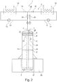
- FIG. 2 shows a non-inventive second embodiment of the energy storage device 1.
- the differences to this will be discussed below.
- An essential difference is that the longitudinal central axis 19 of the fluid container 3 is arranged vertically, that is, in particular, is perpendicular to the above-mentioned substrate.
- the longitudinal central axis 19 extends parallel to the influence of gravity or the gravity vector.
- the fluid container 3 has in this respect, for example, a height which is greater than its width and / or its depth, in particular as its diameter.
- the longitudinal central axis 19 is preferably straight, so that the fluid container 3 or its longitudinal central axis is preferably designed without curvature.
- the fluid container 3 can be fastened, for example, by means of a foundation 20. It may be above ground, in particular completely above ground, but alternatively also underground, in particular completely underground.
- the separating element 6 is formed for example by a cutting disc, which is preferably circular. It has, for example, a first surface 21 and a second surface 22 opposite thereto.
- the first surface 21 is the first fluid storage chamber 7, the second surface 22 of the second fluid storage chamber 8 facing.
- the surfaces 21 and 22 preferably run parallel to each other, in particular over the entire cross section of the fluid container. 3
- a bearing 23 is provided.
- the bearing 23 is associated with a recess, in particular a central recess, of the separating element 6 and a guide element 24.
- the guide element 24 is arranged, for example, centrally in the fluid container 3 and engages it in the longitudinal direction preferably largely or even completely.
- the former is to be understood as meaning a longitudinal extension of the guide element 24 which preferably corresponds to at least 80%, at least 85%, at least 90% or at least 95% of the longitudinal extent of the fluid container 3 or the height of the fluid container 3.
- the guide element 24 is formed in the present embodiment of a tube 25 through which a fluid connection between the fluid storage chamber 7 and the fluid port 4 is realized.
- the fluid connection 4 opens directly or directly into the fluid storage chamber 7 via the tube 25.
- the fluid connection 5 opens directly into the fluid storage chamber 8.
- valves 16 and 27 may be provided.
- loading of the energy storage device is intended to convey fluid from the first fluid storage chamber 7 in the direction of the heat source 14 or through it by means of the pump 13 and then to supply it to the second fluid storage chamber 8 via the fluid connection 5.
- the valves 16 and 26 are opened, while the valves 15 and 27 are closed.
- fluid is conveyed by means of the pump 11 out of the second fluid storage chamber 8 in the direction of the heat consumer 12 or through the latter and subsequently supplied via the fluid connection 4 to the first fluid storage chamber 7.
- the valves 15 and 27 are opened, while preferably the valves 16 and 26 are closed.
- the fluid strands 9 and 10 meet at an intersection 28.
- the valve is fluidically between the intersection 28 and the heat consumer 12, while the valve 16 is fluidically disposed between the intersection 28 and the heat source 14.
- the valve 26 fluidly between the intersection 28 and the fluid port 5 and the valve 27 fluidly between the intersection 28 and the fluid port 4 before.
- a baffle plate 29 or a surge cage may be provided, via which flows the introduced into the fluid storage chamber 8 fluid.
- the baffle or the Schwallhanfig is formed for example by a partition, which is broken through and insofar flow openings for the fluid has.
- the energy storage device 1 With the second embodiment of the energy storage device 1 presented here, basically the same advantages can be achieved as with the use of the first embodiment. Due to the vertical arrangement of the fluid container 3, the energy storage device 1 can be realized with a particularly small footprint. In addition, during the loading and / or unloading of the energy storage device 1, density differences between the colder fluid in the first fluid storage chamber 7 and the warmer fluid in the second fluid storage chamber 8 can be utilized.
Landscapes
- Engineering & Computer Science (AREA)
- Physics & Mathematics (AREA)
- Thermal Sciences (AREA)
- Mechanical Engineering (AREA)
- General Engineering & Computer Science (AREA)
- Filling Or Discharging Of Gas Storage Vessels (AREA)
- Engine Equipment That Uses Special Cycles (AREA)
Applications Claiming Priority (2)
| Application Number | Priority Date | Filing Date | Title |
|---|---|---|---|
| DE102014212676.2A DE102014212676B4 (de) | 2014-07-01 | 2014-07-01 | Energiespeichereinrichtung zur Zwischenspeicherung von thermischer Energie, Kraftwerk mit einer Energiespeichereinrichtung sowie Verfahren zum Betreiben einer Energiespeichereinrichtung |
| PCT/EP2015/063426 WO2016000951A1 (de) | 2014-07-01 | 2015-06-16 | Energiespeichereinrichtung zur zwischenspeicherung von thermischer energie, kraftwerk mit einer energiespeichereinrichtung sowie verfahren zum betreiben einer energiespeichereinrichtung |
Publications (2)
| Publication Number | Publication Date |
|---|---|
| EP3164657A1 EP3164657A1 (de) | 2017-05-10 |
| EP3164657B1 true EP3164657B1 (de) | 2018-05-02 |
Family
ID=53442770
Family Applications (1)
| Application Number | Title | Priority Date | Filing Date |
|---|---|---|---|
| EP15730467.6A Active EP3164657B1 (de) | 2014-07-01 | 2015-06-16 | Energiespeichereinrichtung zur zwischenspeicherung von thermischer energie, kraftwerk mit einer energiespeichereinrichtung sowie verfahren zum betreiben einer energiespeichereinrichtung |
Country Status (9)
| Country | Link |
|---|---|
| US (1) | US10378830B2 (pt) |
| EP (1) | EP3164657B1 (pt) |
| CN (1) | CN107003079B (pt) |
| AU (1) | AU2015283164B2 (pt) |
| DE (1) | DE102014212676B4 (pt) |
| ES (1) | ES2677249T3 (pt) |
| PT (1) | PT3164657T (pt) |
| TR (1) | TR201809845T4 (pt) |
| WO (1) | WO2016000951A1 (pt) |
Families Citing this family (15)
| Publication number | Priority date | Publication date | Assignee | Title |
|---|---|---|---|---|
| DE102016215387A1 (de) * | 2016-08-17 | 2018-02-22 | Mahle International Gmbh | Behältnis zur Ausbildung eines Wärmezwischenspeichers |
| US11796229B2 (en) | 2019-03-22 | 2023-10-24 | Solvcor Technologies. Llc | Systems and methods for high energy density heat transfer |
| US11788798B2 (en) * | 2019-03-22 | 2023-10-17 | Solvcor Technologies, Llc | Systems and adjustable and high energy density thermal storage |
| US12235022B2 (en) * | 2018-02-06 | 2025-02-25 | John Saavedra | Heat transfer device |
| US11359823B2 (en) * | 2018-03-20 | 2022-06-14 | Yanda Zhang | Intelligent hot water heating system with stratified temperature-heating control storage tank |
| DE102018211800A1 (de) | 2018-07-16 | 2020-01-16 | Horst Schierack | Fluidspeichervorrichtung für eine Fluid- und/oder Energiebereitstellungseinrichtung sowie entsprechende Fluid- und/oder Energiebereitstellungseinrichtung |
| DE102019209532A1 (de) * | 2019-06-28 | 2020-12-31 | Horst Schierack | Verfahren zum Betreiben einer Energiebereitstellungseinrichtung für zumindest ein Kraftfahrzeug sowie entsprechende Energiebereitstellungseinrichtung |
| DE102020205593A1 (de) | 2020-05-04 | 2021-11-04 | Horst Schierack | Fluid- und/oder Energiebereitstellungseinrichtung |
| EP4164011B1 (en) * | 2021-10-05 | 2024-04-24 | Volvo Truck Corporation | Heat transfer fluid system for a vehicle |
| US11519504B1 (en) | 2021-12-14 | 2022-12-06 | Norwich Technologies, Inc. | Piston ring for floating piston in a thermal energy storage system |
| US11543191B1 (en) * | 2021-12-14 | 2023-01-03 | Norwich Technologies, Inc. | Thermal energy storage system with parallel connected vessels |
| US11578693B1 (en) | 2021-12-14 | 2023-02-14 | Norwich Technologies, Inc. | Thermal energy storage system including a vessel having hot and cold liquid portions separated by floating piston |
| WO2023113937A1 (en) * | 2021-12-14 | 2023-06-22 | Norwich Technologies, Inc. | Thermal energy storage system with parallel connected vessels |
| US11493281B1 (en) | 2021-12-14 | 2022-11-08 | Norwich Technologies, Inc. | Floating separator piston for a thermal energy storage system |
| DE102023200124A1 (de) | 2023-01-10 | 2024-07-11 | HSI Brainovation GmbH | Verfahren zum Betreiben einer Energiebereitstellungseinrichtung zur Bereitstellung von thermischer Energie sowie entsprechende Energiebereitstellungseinrichtung |
Family Cites Families (24)
| Publication number | Priority date | Publication date | Assignee | Title |
|---|---|---|---|---|
| US2486833A (en) * | 1944-11-17 | 1949-11-01 | Walter J Kelly | Heat storage and supply means |
| DE2724416A1 (de) * | 1977-05-28 | 1978-12-07 | Battelle Institut E V | Speicherelement fuer fluessige waermetraeger in heizanlagen |
| US4501262A (en) * | 1980-04-14 | 1985-02-26 | Halm Instrument Co. Inc. | Solar hot water system without heat exchanger |
| US4390008A (en) * | 1980-06-26 | 1983-06-28 | The United Stated Of America As Represented By The Department Of Energy | Hot water tank for use with a combination of solar energy and heat-pump desuperheating |
| DE3115988A1 (de) * | 1981-04-15 | 1983-01-05 | Engelhardt, Klaus | "warmwasser-speicher" |
| JPS5815702A (ja) * | 1981-07-21 | 1983-01-29 | Mitsui Eng & Shipbuild Co Ltd | 熱水貯蔵発電装置 |
| US4523629A (en) * | 1982-09-30 | 1985-06-18 | The United States Of America As Represented By The United States Department Of Energy | Method and apparatus for operating an improved thermocline storage unit |
| DE19825677A1 (de) | 1998-06-09 | 1999-12-16 | Erdmann Horst | Neuer Typ "Geschlossener Durchlaufspeicher" mit korrespondierendem Kalt- und Heißwasserbereich in getrennten, variablen Volumen |
| US6907923B2 (en) * | 2003-01-13 | 2005-06-21 | Carrier Corporation | Storage tank for hot water systems |
| MX2007011656A (es) * | 2005-03-23 | 2008-10-06 | David M Baker | Metodo y aparato utilitaria para convertir energia termica de baja temperatura a electricidad. |
| DE202006014881U1 (de) * | 2006-09-26 | 2006-12-28 | Vincenz, Manuela | Schichtisolierung |
| US20090090109A1 (en) * | 2007-06-06 | 2009-04-09 | Mills David R | Granular thermal energy storage mediums and devices for thermal energy storage systems |
| WO2009079791A1 (en) * | 2007-12-20 | 2009-07-02 | Boulay Andre | Multi-chamber water heater |
| DE602008005008D1 (de) * | 2008-07-01 | 2011-03-31 | Ingenieria Y Sist S S A | Dualwärmeenergiespeichertank |
| WO2011035213A2 (en) * | 2009-09-17 | 2011-03-24 | Xiaodong Xiang | Systems and methods of thermal transfer and/or storage |
| US9671171B2 (en) * | 2009-09-17 | 2017-06-06 | Bluelagoon Technologies Ltd. | Systems and methods of thermal transfer and/or storage |
| US20110289924A1 (en) * | 2010-05-28 | 2011-12-01 | Anton Pietsch | High-density energy storage and retrieval |
| DE102010034294A1 (de) * | 2010-08-13 | 2012-02-16 | Linde Aktiengesellschaft | Wärmespeicher |
| WO2012040110A2 (en) * | 2010-09-20 | 2012-03-29 | State Of Oregon Acting By And Through The State Board Of Higher Education On Behalf Of Oregon State University | A system and method for storing energy and purifying fluid |
| US8997511B2 (en) * | 2010-09-21 | 2015-04-07 | Denering Berrio | Heating or cooling system featuring a split buffer tank |
| CN103512186A (zh) * | 2012-06-21 | 2014-01-15 | 赵旭阳 | 具有卧式热水隔离器的热水器及其热胆 |
| US10837716B2 (en) * | 2015-09-30 | 2020-11-17 | Siemens Gamesa Renewable Energy A/S | Heat exchange system with a heat exchange chamber in with a thermal insulation layer, method for manufacturing the heat exchange system and method for exchanging heat by using the heat exchange system |
| US10982909B2 (en) * | 2015-09-30 | 2021-04-20 | Siemens Gamesa Renewable Energy A/S | Heat exchange system with compensation of dimension change of heat storage material and method for exchanging heat by using the heat exchange system |
| ES2735673T3 (es) * | 2015-09-30 | 2019-12-19 | Siemens Gamesa Renewable Energy As | Sistema de intercambio de calor con dispositivo de movimiento de fluido activo conjunto para el modo de carga y el modo de descarga y método para el intercambio de calor mediante el uso del sistema de intercambio de calor |
-
2014
- 2014-07-01 DE DE102014212676.2A patent/DE102014212676B4/de not_active Expired - Fee Related
-
2015
- 2015-06-16 AU AU2015283164A patent/AU2015283164B2/en not_active Ceased
- 2015-06-16 PT PT157304676T patent/PT3164657T/pt unknown
- 2015-06-16 CN CN201580046822.6A patent/CN107003079B/zh not_active Expired - Fee Related
- 2015-06-16 EP EP15730467.6A patent/EP3164657B1/de active Active
- 2015-06-16 TR TR2018/09845T patent/TR201809845T4/tr unknown
- 2015-06-16 WO PCT/EP2015/063426 patent/WO2016000951A1/de not_active Ceased
- 2015-06-16 US US15/323,555 patent/US10378830B2/en not_active Expired - Fee Related
- 2015-06-16 ES ES15730467.6T patent/ES2677249T3/es active Active
Non-Patent Citations (1)
| Title |
|---|
| None * |
Also Published As
| Publication number | Publication date |
|---|---|
| US20170234626A1 (en) | 2017-08-17 |
| ES2677249T3 (es) | 2018-07-31 |
| EP3164657A1 (de) | 2017-05-10 |
| WO2016000951A1 (de) | 2016-01-07 |
| US10378830B2 (en) | 2019-08-13 |
| DE102014212676B4 (de) | 2019-03-14 |
| CN107003079A (zh) | 2017-08-01 |
| CN107003079B (zh) | 2019-07-26 |
| TR201809845T4 (tr) | 2018-07-23 |
| AU2015283164B2 (en) | 2020-02-06 |
| PT3164657T (pt) | 2018-07-25 |
| DE102014212676A1 (de) | 2016-01-07 |
| AU2015283164A1 (en) | 2017-02-23 |
Similar Documents
| Publication | Publication Date | Title |
|---|---|---|
| EP3164657B1 (de) | Energiespeichereinrichtung zur zwischenspeicherung von thermischer energie, kraftwerk mit einer energiespeichereinrichtung sowie verfahren zum betreiben einer energiespeichereinrichtung | |
| EP3186506B1 (de) | Vorrichtung und verfahren zum speichern von energie | |
| EP3002528B1 (de) | Wärmespeicher und Verfahren zum Betreiben eines Wärmespeichers | |
| EP2450549A2 (de) | Druckstufen-Wärme-Speicherkraftwerk bzw. Energiespeicherverfahren zum zeitweiligen Speichern von Energie in Form von Druckenergie in einem kompressiblen Medium in Form von Wärmeenergie | |
| DE102012015732B4 (de) | Verfahren und Anordnungen zur Aufnahme und Abgabe elektrischer Energie in Gasdruckspeicherwerken | |
| WO2014057014A1 (de) | Speichereinrichtung zur zwischenspeicherung von thermischer energie sowie verfahren zum betreiben einer speichereinrichtung | |
| EP3633303B1 (de) | Energiespeicher zum speichern von elektrischer energie als wärme und verfahren hierzu | |
| WO2015180997A1 (de) | Elektrischer energiespeicher | |
| EP2825737A1 (de) | Anlage zur speicherung und abgabe von thermischer energie mit einem wärmespeicher und einem kältespeicher und verfahren zu deren betrieb | |
| DE102013213317A1 (de) | Verfahren und System zur Wärmeübertragung für ein Fahrzeug | |
| EP2713130B1 (de) | Thermischer Speicher für Kälteanlagen | |
| EP3036790B1 (de) | Thermisches speichersystem mit hochtemperaturbatterie | |
| DE102011051305B4 (de) | Pumpspeicherkraftwerk | |
| DE102011118106A1 (de) | Wärmespeichermodul und modularer Wärmespeicher | |
| DE102021102231A1 (de) | Elektrisches Energiespeichersystem und Verfahren zur Ein- und Ausspeicherung elektrischer Energie sowie Computerprogramm | |
| EP2965023B1 (de) | Solarfeld für ein linear knozentrierendes solarkraftwerk | |
| WO2018114012A1 (de) | Einrichtung und verfahren zum speichern von energie sowie verwendung einer kaverne | |
| WO2015027988A2 (de) | Drainagesystem für ein solarthermisches kollektorfeld | |
| EP3756934A1 (de) | Verfahren zum betreiben einer energiebereitstellungseinrichtung für zumindest ein kraftfahrzeug sowie entsprechende energiebereitstellungeinrichtung | |
| DE102013200212A1 (de) | Stromkollektoren für Batteriezellen | |
| DE102018201619B4 (de) | Wärmespeichervorrichtung, Arbeitsvorrichtung, Verfahren zum Betreiben einer Wärmespeichervorrichtung und Verfahren zum Betreiben einer Arbeitsvorrichtung | |
| DE2744970C3 (de) | Gasturbinenanlage | |
| WO2021037348A1 (de) | Geothermische vorrichtung und verfahren | |
| DE102020105211A1 (de) | Vorrichtung und Verfahren zur Speicherung von elektrischer Energie in Druckenergie | |
| DE102014226406A1 (de) | Hybridfahrzeug |
Legal Events
| Date | Code | Title | Description |
|---|---|---|---|
| PUAI | Public reference made under article 153(3) epc to a published international application that has entered the european phase |
Free format text: ORIGINAL CODE: 0009012 |
|
| 17P | Request for examination filed |
Effective date: 20170201 |
|
| AK | Designated contracting states |
Kind code of ref document: A1 Designated state(s): AL AT BE BG CH CY CZ DE DK EE ES FI FR GB GR HR HU IE IS IT LI LT LU LV MC MK MT NL NO PL PT RO RS SE SI SK SM TR |
|
| AX | Request for extension of the european patent |
Extension state: BA ME |
|
| RAP1 | Party data changed (applicant data changed or rights of an application transferred) |
Owner name: SCHIERACK GREEN TECHNOLOGY GMBH |
|
| DAV | Request for validation of the european patent (deleted) | ||
| DAX | Request for extension of the european patent (deleted) | ||
| GRAP | Despatch of communication of intention to grant a patent |
Free format text: ORIGINAL CODE: EPIDOSNIGR1 |
|
| GRAJ | Information related to disapproval of communication of intention to grant by the applicant or resumption of examination proceedings by the epo deleted |
Free format text: ORIGINAL CODE: EPIDOSDIGR1 |
|
| INTG | Intention to grant announced |
Effective date: 20180130 |
|
| GRAP | Despatch of communication of intention to grant a patent |
Free format text: ORIGINAL CODE: EPIDOSNIGR1 |
|
| INTC | Intention to grant announced (deleted) | ||
| GRAS | Grant fee paid |
Free format text: ORIGINAL CODE: EPIDOSNIGR3 |
|
| GRAA | (expected) grant |
Free format text: ORIGINAL CODE: 0009210 |
|
| INTG | Intention to grant announced |
Effective date: 20180313 |
|
| AK | Designated contracting states |
Kind code of ref document: B1 Designated state(s): AL AT BE BG CH CY CZ DE DK EE ES FI FR GB GR HR HU IE IS IT LI LT LU LV MC MK MT NL NO PL PT RO RS SE SI SK SM TR |
|
| REG | Reference to a national code |
Ref country code: GB Ref legal event code: FG4D Free format text: NOT ENGLISH |
|
| REG | Reference to a national code |
Ref country code: CH Ref legal event code: EP Ref country code: AT Ref legal event code: REF Ref document number: 995725 Country of ref document: AT Kind code of ref document: T Effective date: 20180515 |
|
| REG | Reference to a national code |
Ref country code: DE Ref legal event code: R096 Ref document number: 502015004145 Country of ref document: DE Ref country code: IE Ref legal event code: FG4D Free format text: LANGUAGE OF EP DOCUMENT: GERMAN |
|
| REG | Reference to a national code |
Ref country code: FR Ref legal event code: PLFP Year of fee payment: 4 |
|
| REG | Reference to a national code |
Ref country code: PT Ref legal event code: SC4A Ref document number: 3164657 Country of ref document: PT Date of ref document: 20180725 Kind code of ref document: T Free format text: AVAILABILITY OF NATIONAL TRANSLATION Effective date: 20180718 |
|
| REG | Reference to a national code |
Ref country code: ES Ref legal event code: FG2A Ref document number: 2677249 Country of ref document: ES Kind code of ref document: T3 Effective date: 20180731 |
|
| REG | Reference to a national code |
Ref country code: NL Ref legal event code: MP Effective date: 20180502 |
|
| REG | Reference to a national code |
Ref country code: LT Ref legal event code: MG4D |
|
| PG25 | Lapsed in a contracting state [announced via postgrant information from national office to epo] |
Ref country code: LT Free format text: LAPSE BECAUSE OF FAILURE TO SUBMIT A TRANSLATION OF THE DESCRIPTION OR TO PAY THE FEE WITHIN THE PRESCRIBED TIME-LIMIT Effective date: 20180502 Ref country code: SE Free format text: LAPSE BECAUSE OF FAILURE TO SUBMIT A TRANSLATION OF THE DESCRIPTION OR TO PAY THE FEE WITHIN THE PRESCRIBED TIME-LIMIT Effective date: 20180502 Ref country code: NO Free format text: LAPSE BECAUSE OF FAILURE TO SUBMIT A TRANSLATION OF THE DESCRIPTION OR TO PAY THE FEE WITHIN THE PRESCRIBED TIME-LIMIT Effective date: 20180802 Ref country code: FI Free format text: LAPSE BECAUSE OF FAILURE TO SUBMIT A TRANSLATION OF THE DESCRIPTION OR TO PAY THE FEE WITHIN THE PRESCRIBED TIME-LIMIT Effective date: 20180502 Ref country code: BG Free format text: LAPSE BECAUSE OF FAILURE TO SUBMIT A TRANSLATION OF THE DESCRIPTION OR TO PAY THE FEE WITHIN THE PRESCRIBED TIME-LIMIT Effective date: 20180802 |
|
| PG25 | Lapsed in a contracting state [announced via postgrant information from national office to epo] |
Ref country code: HR Free format text: LAPSE BECAUSE OF FAILURE TO SUBMIT A TRANSLATION OF THE DESCRIPTION OR TO PAY THE FEE WITHIN THE PRESCRIBED TIME-LIMIT Effective date: 20180502 Ref country code: RS Free format text: LAPSE BECAUSE OF FAILURE TO SUBMIT A TRANSLATION OF THE DESCRIPTION OR TO PAY THE FEE WITHIN THE PRESCRIBED TIME-LIMIT Effective date: 20180502 Ref country code: NL Free format text: LAPSE BECAUSE OF FAILURE TO SUBMIT A TRANSLATION OF THE DESCRIPTION OR TO PAY THE FEE WITHIN THE PRESCRIBED TIME-LIMIT Effective date: 20180502 Ref country code: LV Free format text: LAPSE BECAUSE OF FAILURE TO SUBMIT A TRANSLATION OF THE DESCRIPTION OR TO PAY THE FEE WITHIN THE PRESCRIBED TIME-LIMIT Effective date: 20180502 Ref country code: GR Free format text: LAPSE BECAUSE OF FAILURE TO SUBMIT A TRANSLATION OF THE DESCRIPTION OR TO PAY THE FEE WITHIN THE PRESCRIBED TIME-LIMIT Effective date: 20180803 |
|
| PG25 | Lapsed in a contracting state [announced via postgrant information from national office to epo] |
Ref country code: DK Free format text: LAPSE BECAUSE OF FAILURE TO SUBMIT A TRANSLATION OF THE DESCRIPTION OR TO PAY THE FEE WITHIN THE PRESCRIBED TIME-LIMIT Effective date: 20180502 Ref country code: SK Free format text: LAPSE BECAUSE OF FAILURE TO SUBMIT A TRANSLATION OF THE DESCRIPTION OR TO PAY THE FEE WITHIN THE PRESCRIBED TIME-LIMIT Effective date: 20180502 Ref country code: EE Free format text: LAPSE BECAUSE OF FAILURE TO SUBMIT A TRANSLATION OF THE DESCRIPTION OR TO PAY THE FEE WITHIN THE PRESCRIBED TIME-LIMIT Effective date: 20180502 Ref country code: PL Free format text: LAPSE BECAUSE OF FAILURE TO SUBMIT A TRANSLATION OF THE DESCRIPTION OR TO PAY THE FEE WITHIN THE PRESCRIBED TIME-LIMIT Effective date: 20180502 Ref country code: RO Free format text: LAPSE BECAUSE OF FAILURE TO SUBMIT A TRANSLATION OF THE DESCRIPTION OR TO PAY THE FEE WITHIN THE PRESCRIBED TIME-LIMIT Effective date: 20180502 Ref country code: CZ Free format text: LAPSE BECAUSE OF FAILURE TO SUBMIT A TRANSLATION OF THE DESCRIPTION OR TO PAY THE FEE WITHIN THE PRESCRIBED TIME-LIMIT Effective date: 20180502 |
|
| REG | Reference to a national code |
Ref country code: CH Ref legal event code: PL |
|
| REG | Reference to a national code |
Ref country code: DE Ref legal event code: R097 Ref document number: 502015004145 Country of ref document: DE |
|
| PG25 | Lapsed in a contracting state [announced via postgrant information from national office to epo] |
Ref country code: SM Free format text: LAPSE BECAUSE OF FAILURE TO SUBMIT A TRANSLATION OF THE DESCRIPTION OR TO PAY THE FEE WITHIN THE PRESCRIBED TIME-LIMIT Effective date: 20180502 |
|
| REG | Reference to a national code |
Ref country code: BE Ref legal event code: MM Effective date: 20180630 |
|
| PLBE | No opposition filed within time limit |
Free format text: ORIGINAL CODE: 0009261 |
|
| STAA | Information on the status of an ep patent application or granted ep patent |
Free format text: STATUS: NO OPPOSITION FILED WITHIN TIME LIMIT |
|
| REG | Reference to a national code |
Ref country code: IE Ref legal event code: MM4A |
|
| PG25 | Lapsed in a contracting state [announced via postgrant information from national office to epo] |
Ref country code: LU Free format text: LAPSE BECAUSE OF NON-PAYMENT OF DUE FEES Effective date: 20180616 Ref country code: MC Free format text: LAPSE BECAUSE OF FAILURE TO SUBMIT A TRANSLATION OF THE DESCRIPTION OR TO PAY THE FEE WITHIN THE PRESCRIBED TIME-LIMIT Effective date: 20180502 |
|
| 26N | No opposition filed |
Effective date: 20190205 |
|
| PG25 | Lapsed in a contracting state [announced via postgrant information from national office to epo] |
Ref country code: CH Free format text: LAPSE BECAUSE OF NON-PAYMENT OF DUE FEES Effective date: 20180630 Ref country code: IE Free format text: LAPSE BECAUSE OF NON-PAYMENT OF DUE FEES Effective date: 20180616 Ref country code: LI Free format text: LAPSE BECAUSE OF NON-PAYMENT OF DUE FEES Effective date: 20180630 |
|
| PG25 | Lapsed in a contracting state [announced via postgrant information from national office to epo] |
Ref country code: BE Free format text: LAPSE BECAUSE OF NON-PAYMENT OF DUE FEES Effective date: 20180630 Ref country code: SI Free format text: LAPSE BECAUSE OF FAILURE TO SUBMIT A TRANSLATION OF THE DESCRIPTION OR TO PAY THE FEE WITHIN THE PRESCRIBED TIME-LIMIT Effective date: 20180502 |
|
| PG25 | Lapsed in a contracting state [announced via postgrant information from national office to epo] |
Ref country code: AL Free format text: LAPSE BECAUSE OF FAILURE TO SUBMIT A TRANSLATION OF THE DESCRIPTION OR TO PAY THE FEE WITHIN THE PRESCRIBED TIME-LIMIT Effective date: 20180502 |
|
| PG25 | Lapsed in a contracting state [announced via postgrant information from national office to epo] |
Ref country code: MT Free format text: LAPSE BECAUSE OF FAILURE TO SUBMIT A TRANSLATION OF THE DESCRIPTION OR TO PAY THE FEE WITHIN THE PRESCRIBED TIME-LIMIT Effective date: 20180502 |
|
| PG25 | Lapsed in a contracting state [announced via postgrant information from national office to epo] |
Ref country code: CY Free format text: LAPSE BECAUSE OF FAILURE TO SUBMIT A TRANSLATION OF THE DESCRIPTION OR TO PAY THE FEE WITHIN THE PRESCRIBED TIME-LIMIT Effective date: 20180502 Ref country code: MK Free format text: LAPSE BECAUSE OF NON-PAYMENT OF DUE FEES Effective date: 20180502 Ref country code: HU Free format text: LAPSE BECAUSE OF FAILURE TO SUBMIT A TRANSLATION OF THE DESCRIPTION OR TO PAY THE FEE WITHIN THE PRESCRIBED TIME-LIMIT; INVALID AB INITIO Effective date: 20150616 |
|
| PG25 | Lapsed in a contracting state [announced via postgrant information from national office to epo] |
Ref country code: IS Free format text: LAPSE BECAUSE OF FAILURE TO SUBMIT A TRANSLATION OF THE DESCRIPTION OR TO PAY THE FEE WITHIN THE PRESCRIBED TIME-LIMIT Effective date: 20180902 |
|
| PGFP | Annual fee paid to national office [announced via postgrant information from national office to epo] |
Ref country code: PT Payment date: 20220609 Year of fee payment: 8 Ref country code: GB Payment date: 20220627 Year of fee payment: 8 |
|
| PGFP | Annual fee paid to national office [announced via postgrant information from national office to epo] |
Ref country code: FR Payment date: 20230630 Year of fee payment: 9 Ref country code: DE Payment date: 20230626 Year of fee payment: 9 |
|
| P01 | Opt-out of the competence of the unified patent court (upc) registered |
Effective date: 20230712 |
|
| PGFP | Annual fee paid to national office [announced via postgrant information from national office to epo] |
Ref country code: TR Payment date: 20230615 Year of fee payment: 9 Ref country code: AT Payment date: 20230621 Year of fee payment: 9 |
|
| PGFP | Annual fee paid to national office [announced via postgrant information from national office to epo] |
Ref country code: IT Payment date: 20230621 Year of fee payment: 9 Ref country code: ES Payment date: 20230830 Year of fee payment: 9 |
|
| PGFP | Annual fee paid to national office [announced via postgrant information from national office to epo] |
Ref country code: FR Payment date: 20230721 Year of fee payment: 9 |
|
| PG25 | Lapsed in a contracting state [announced via postgrant information from national office to epo] |
Ref country code: PT Free format text: LAPSE BECAUSE OF NON-PAYMENT OF DUE FEES Effective date: 20231218 |
|
| GBPC | Gb: european patent ceased through non-payment of renewal fee |
Effective date: 20230616 |
|
| PG25 | Lapsed in a contracting state [announced via postgrant information from national office to epo] |
Ref country code: GB Free format text: LAPSE BECAUSE OF NON-PAYMENT OF DUE FEES Effective date: 20230616 |
|
| REG | Reference to a national code |
Ref country code: DE Ref legal event code: R119 Ref document number: 502015004145 Country of ref document: DE |
|
| REG | Reference to a national code |
Ref country code: AT Ref legal event code: MM01 Ref document number: 995725 Country of ref document: AT Kind code of ref document: T Effective date: 20240616 |
|
| PG25 | Lapsed in a contracting state [announced via postgrant information from national office to epo] |
Ref country code: DE Free format text: LAPSE BECAUSE OF NON-PAYMENT OF DUE FEES Effective date: 20250101 |
|
| PG25 | Lapsed in a contracting state [announced via postgrant information from national office to epo] |
Ref country code: AT Free format text: LAPSE BECAUSE OF NON-PAYMENT OF DUE FEES Effective date: 20240616 |
|
| PG25 | Lapsed in a contracting state [announced via postgrant information from national office to epo] |
Ref country code: FR Free format text: LAPSE BECAUSE OF NON-PAYMENT OF DUE FEES Effective date: 20240630 |
|
| PG25 | Lapsed in a contracting state [announced via postgrant information from national office to epo] |
Ref country code: IT Free format text: LAPSE BECAUSE OF NON-PAYMENT OF DUE FEES Effective date: 20240616 |
|
| REG | Reference to a national code |
Ref country code: ES Ref legal event code: FD2A Effective date: 20250731 |
|
| PG25 | Lapsed in a contracting state [announced via postgrant information from national office to epo] |
Ref country code: ES Free format text: LAPSE BECAUSE OF NON-PAYMENT OF DUE FEES Effective date: 20240617 |