EP3165200B1 - Lendenorthese - Google Patents
Lendenorthese Download PDFInfo
- Publication number
- EP3165200B1 EP3165200B1 EP15814697.7A EP15814697A EP3165200B1 EP 3165200 B1 EP3165200 B1 EP 3165200B1 EP 15814697 A EP15814697 A EP 15814697A EP 3165200 B1 EP3165200 B1 EP 3165200B1
- Authority
- EP
- European Patent Office
- Prior art keywords
- section
- band
- band section
- supporter
- contact
- Prior art date
- Legal status (The legal status is an assumption and is not a legal conclusion. Google has not performed a legal analysis and makes no representation as to the accuracy of the status listed.)
- Active
Links
Images



Classifications
-
- A—HUMAN NECESSITIES
- A61—MEDICAL OR VETERINARY SCIENCE; HYGIENE
- A61F—FILTERS IMPLANTABLE INTO BLOOD VESSELS; PROSTHESES; DEVICES PROVIDING PATENCY TO, OR PREVENTING COLLAPSING OF, TUBULAR STRUCTURES OF THE BODY, e.g. STENTS; ORTHOPAEDIC, NURSING OR CONTRACEPTIVE DEVICES; FOMENTATION; TREATMENT OR PROTECTION OF EYES OR EARS; BANDAGES, DRESSINGS OR ABSORBENT PADS; FIRST-AID KITS
- A61F5/00—Orthopaedic methods or devices for non-surgical treatment of bones or joints; Nursing devices ; Anti-rape devices
- A61F5/01—Orthopaedic devices, e.g. long-term immobilising or pressure directing devices for treating broken or deformed bones such as splints, casts or braces
- A61F5/02—Orthopaedic corsets
- A61F5/028—Braces for providing support to the lower back, e.g. lumbo sacral supports
-
- A—HUMAN NECESSITIES
- A61—MEDICAL OR VETERINARY SCIENCE; HYGIENE
- A61F—FILTERS IMPLANTABLE INTO BLOOD VESSELS; PROSTHESES; DEVICES PROVIDING PATENCY TO, OR PREVENTING COLLAPSING OF, TUBULAR STRUCTURES OF THE BODY, e.g. STENTS; ORTHOPAEDIC, NURSING OR CONTRACEPTIVE DEVICES; FOMENTATION; TREATMENT OR PROTECTION OF EYES OR EARS; BANDAGES, DRESSINGS OR ABSORBENT PADS; FIRST-AID KITS
- A61F5/00—Orthopaedic methods or devices for non-surgical treatment of bones or joints; Nursing devices ; Anti-rape devices
- A61F5/01—Orthopaedic devices, e.g. long-term immobilising or pressure directing devices for treating broken or deformed bones such as splints, casts or braces
- A61F5/02—Orthopaedic corsets
-
- A—HUMAN NECESSITIES
- A61—MEDICAL OR VETERINARY SCIENCE; HYGIENE
- A61F—FILTERS IMPLANTABLE INTO BLOOD VESSELS; PROSTHESES; DEVICES PROVIDING PATENCY TO, OR PREVENTING COLLAPSING OF, TUBULAR STRUCTURES OF THE BODY, e.g. STENTS; ORTHOPAEDIC, NURSING OR CONTRACEPTIVE DEVICES; FOMENTATION; TREATMENT OR PROTECTION OF EYES OR EARS; BANDAGES, DRESSINGS OR ABSORBENT PADS; FIRST-AID KITS
- A61F5/00—Orthopaedic methods or devices for non-surgical treatment of bones or joints; Nursing devices ; Anti-rape devices
- A61F5/01—Orthopaedic devices, e.g. long-term immobilising or pressure directing devices for treating broken or deformed bones such as splints, casts or braces
- A61F5/03—Corsets or bandages for abdomen, teat or breast support, with or without pads
Definitions
- the present invention relates to a supporter capable of supporting a wearer's daily motion, and particularly, to a supporter capable of supporting the entire waist portion of a wearer including the pelvis of the wearer.
- a belt which supports the waist portion and the pelvis in a main body belt having a width which covers the waist portion and the pelvis portion, hook-and-loop fasteners for mounting and dismounting are provided at both right and left end portions of the main body belt, and the belt can be wound and mounted by adjusting tightening on the abdomen side of a wearer, and a belt for the waist portion and a belt for the pelvis, the tightening forces of which can be individually adjusted, are provided in parallel on the inner surface side of the main body belt, whereby the waist portion and the pelvis are supported at the same time by the belt for the waist portion and the belt for the pelvis provided in the main body belt (refer to, for example, JP 3 146 163 U ).
- a fixed plate formed by curing a forming material with a flexible base fabric impregnated with water-curable resin so as to correspond to the shape of the waist portion is joined to an abdominal bandage by belts (refer to, for example, JP-A-6-142126 ).
- JP-A-2013-138823 which represents the closest prior art.
- This known supporter is provided with: a body section having a back-contact section; loops disposed on the front surfaces of both ends of the body section; a first auxiliary band section which is fixed, at one end thereof, to an upper end of a left side of the back-contact section and, at the other end thereof, to a lower end of a right side of the back-contact section; a second auxiliary band section which is paired with the first auxiliary band section; a first ring which is disposed so as to be slidable between one end and the other end of the first auxiliary band section; a second ring which is paired with the first ring; a first adjustment band section having one end fixed to the loops on the right end side of the body section, and the other end capable of being engaged with the loops on the right end side of the body section; and a second adjustment band section which is paired with the first adjustment band section.
- the support has a waistband of substantially unstretchable construction for providing abdominal and lumbosacral support.
- An elastic band is operatively connected to the outer surface of the waistband, which has a generally V shape, wherein the waistband resists riding up on a wearer.
- the belt for the waist portion (an upper belt) and the belt for the pelvis (a lower belt) are provided in parallel on a back part (the fixed plate), whereby the belt for the waist portion (the upper belt) presses the slightly upper side of the center of the back part (the fixed plate) and the belt for the pelvis (the lower belt) presses the slightly lower side of the center of the back part (the fixed plate).
- the back portion of a wearer is curved, and therefore, in a structure in which the belt for the waist portion (the upper belt) and the belt for the pelvis (the lower belt) equally press upper and lower portions closer to the center of the back part (the fixed plate), like the belt (the lumbago band) which supports the waist portion and the pelvis, of the related art, floating of the back part (the fixed plate) from the back portion of the wearer occurs on the side of an upper side of the back part (the fixed plate), and thus there is a problem in which it is not possible to sufficiently support the waist portion of the wearer.
- the present invention has been made to solve the problems as described above and has an object to provide a supporter in which even in a back-contact section having a wide width, it is possible to prevent floating of the supporter from the back portion of a wearer in an upper side and reliably support the waist portion of the wearer.
- the supporter according to the present invention is characterized by a band-shaped support band section which includes a band-shaped member having stretchability in a longitudinal direction and is fixed to the back-contact section, and in which hooks of a hook-and-loop fastener is disposed at each of both end portions.
- the supporters according to the present invention even in a back-contact section having a wide width, floating of the supporter from the back portion of a wearer in an upper side and a lower side is prevented, and by applying relative importance to the pressing force from each band section in the upper side and the lower side of the back-contact section, it is possible to provide an optimal supporter according to the type of a lumbago.
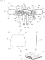
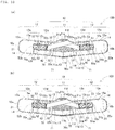
- a supporter 100 is used as a supporter (a corset) for the waist (in particular, for the pelvis) and roughly comprises a body section 10, a pair of right and left first and second auxiliary band sections 31 and 32, a pair of right and left first and second rings 41 and 42, a pair of right and left first and second adjustment band sections 51 and 52, and a support band section 70, as shown in Figs. 1 and 2 .
- the body section 10 is composed of a band-shaped member and is provided with a back-contact section 11 which is disposed at a central portion of the approximately center of the band-shaped member and brought into contact with the back portion of a wearer, and protruding sections 12 which are disposed at both end portions on both sides of the back-contact section 11 and protrude upward with an upper side 12a and a lower side 12b of each of both end portions of the body section 10 being substantially parallel to each other and with an angle (on the acute angle side) between a horizontal portion of a lower side 11b of the back-contact section 11 and each of the upper side 12a and the lower side 12b being ⁇ 1 (for example, ⁇ 1 is in a range of 12° to 14°).
- the body section 10 has a planar shape which is line-symmetric with a line segment connecting the midpoint of an upper side 11a and the midpoint of the lower side 11b of the back-contact section 11 as the axis of symmetry, and is circled around the waist portion of a wearer with the lining surface (refer to Fig. 1(b) ) brought into contact with the waist portion.
- inner layers which are sandwiched between the grosgrain tapes 13 from the front surface and the lining surface of the body section 10 are flattened without overlapping of a material of the back-contact section 11 and a material of the protruding section 12, whereby the thinning of the supporter 100 is attained and a neat feeling of wearing is realized, and even if a layering is performed on the supporter 100, it hardly affects an outerwear.
- the back-contact section 11 has a substantially isosceles trapezoidal planar shape in which corner portions of both ends of the upper side 11a are curved so as to make the upper side 11a and the upper side 12a of the protruding section 12 continuous in an approximately S-shape, and an angle (on the acute angle side) ⁇ 2 between each of the opposite sides (a left side 11c and a right side 11d) which are not parallel to each other and the horizontal portion of the lower side 11b of the back-contact section 11 is 90°- ⁇ 1 (for example, in a case where ⁇ 1 is in a range of 12° to 14°, ⁇ 2 is in a range of 76° to 78°).
- the back-contact section 11 has a wide width (for example, in a range of 19 cm to 25 cm), thereby being able to reliably support the pelvis of a wearer to correspond to the size of the pelvis.
- the back-contact section 11 may have a planar shape having a wide width with respect to the protruding section 12 by curving corner portions of both ends of the lower side 11b so as to make the lower side 11b and the lower side 12b of the protruding section 12 continuous in an approximately S-shape.
- the back-contact section 11 is a bag-like body having an opening 11e in the lining surface and has a configuration in which a pressing section 60 made of a hard plate-like body which has high rigidity and does not have stretchability can be inserted into the bag-like body as a sock liner.
- a pressing section 60 made of a hard plate-like body which has high rigidity and does not have stretchability
- the back-contact section 11 being made to be a bag-like body is preferable, because it is possible to accommodate an accessory according to the needs of a wearer therein and it is possible to improve the convenience of the supporter 100, such as increasing the warmth of the supporter 100 by accommodating, for example, a pocket heater therein.
- a crochet knitted material (a crochet-knitted fabric 11g) which is knitted using a polyurethane yarn and a heat-resistant polyester yarn by a crochet warp knitting machine is used for a back fabric, whereby the sense of touch is soft and a feeling against the back portion of a wearer is good, and by overlapping two crochet-knitted fabrics 11g at the opening 11e, it is possible to prevent an accessory such as a pocket heater accommodated in the bag-like body from coming out from the opening 11e.
- a crochet knitted material (a crochet-knitted fabric 11g) which is knitted using a polyurethane yarn and a heat-resistant polyester yarn by a crochet warp knitting machine is used for a back fabric, whereby the sense of touch is soft and a feeling against the back portion of a wearer is good, and by overlapping two crochet-knitted fabrics 11g at the opening 11e, it is possible to prevent an accessory such as a pocket heater accommodated in the bag-like body from coming out from the
- a warp knitted fabric to which resin processing is not applied is used as the back fabric, whereby even if the knitted fabric is cut, the knitting yarn does not become loose from the cut-off edge, and thus it is possible to process the knitted fabric into a free shape, and it is possible to provide desired stretchability to enable the insertion of an accessory into the bag-like body.
- the warp knitting machine is classified roughly into a raschel warp knitting machine which forms a knitted fabric (a raschel knitted fabric) having a specialized pattern by using needles in various ways, and a tricot warp knitting machine which forms a knitted fabric (a tricot knitted fabric) specialized in high production rather than a pattern. Further, the raschel warp knitting machine is subdivided into a double raschel warp knitting machine, a Rasserina warp knitting machine, a lace warp knitting machine or a crochet warp knitting machine (a crochet knitting machine), and the like.
- the warp knitting creates a knitted fabric by creating knitted stitches in a longitudinal direction (a knitting direction) and combining the knitted stitches by using a large number of warps (warping yarns) arranged in parallel one by one.
- a method of creating a knitted fabric as a whole while mutually entangling warps adjacent to each other or a method of forming a knitted fabric as a whole by creating a large number of independent chain stitches by each of warps and inserting another set of warps prepared separately into the chain stitches, thereby connecting the chain stitches in a transverse direction while collecting several chain stitches, can be given.
- the warp knitting has the features such as high productivity and a large knitted width, in addition to fray being difficult and elongation in the transverse direction (the direction perpendicular to the knitting direction) being small.
- a resin panel made of polypropylene (PP) having a melting point in a range of 150°C to 160°C and having more excellent heat resistance than a polyethylene material having a melting point in a range of 105°C to 120°C is used, whereby in a case where a pocket heater is accommodated in the back-contact section 11, it is possible to suppress the deformation of the pressing section 60 due to heat generation of the pocket heater.
- PP polypropylene
- the pressing section 60 has a substantially isosceles trapezoidal planar shape conforming to the planar shape of the back-contact section 11, and has a shape in which four corner portions are rounded and a concave portion 63 is formed at the center of each of an upper bottom 61 and a lower bottom 62, whereby the pressing section 60 is easily twisted with a line segment connecting the midpoint of the upper bottom 61 and the midpoint of the lower bottom 62 as a basis, a repulsive force is generated against the twist, and an axopodium is assisted with respect to the movement of a wearer, thereby facilitating the walking of the wearer.
- the concave portion 63 is not formed in the pressing section 60
- the center of the upper bottom 61 protrudes most highly, and a protruding portion of the pressing section 60 comes into contact with the back portion of a wearer, thereby causing pain, and therefore, it is preferable to form the concave portion 63 at the center of the upper bottom 61.
- the protruding section 12 is composed of an area having stretchability (hereinafter referred to as a stretchable portion 12d), which is disposed on each of both sides of the back-contact section 11, and an area having no stretchability (hereinafter referred to as a non-stretchable portion 12e), which is disposed adjacent to the stretchable portion 12d.
- a stretchable portion 12d an area having stretchability
- a non-stretchable portion 12e an area having no stretchability
- the stretchable portion 12d of the protruding section 12 is composed of a power net fabric 12c which is woven by a needle loom and in which in addition to a polyurethane yarn and a polyester yarn, a monofilament (single fiber) yarn made of nylon is woven in order to prevent folding of the fabric, and is a fabric in which stretchability in the longitudinal direction L is provided and stretchability in a short side direction S is suppressed.
- the stretchable portion 12d of the protruding section 12 has stretchability higher than the stretchability of the first auxiliary band section 31 and the second auxiliary band section 32 (described later).
- gathered yarns for example, 10 pieces
- monofilament yarns for example, 50 deniers per piece
- the tip of the monofilament yarn is suppressed from protruding from the cut edge while a desired hardness and air permeability are maintained, and even if the monofilament yarn protrudes, since the thickness of a single monofilament is thin, the tip of the monofilament yarn does not pierce a wearer, and thus it is possible to reduce irritation to the skin of a wearer.
- Hook-and-loop fasteners are disposed at the front surfaces of both ends (a left end 10a and a right end 10b) of the body section 10 and the lining surface of the left end 10a or the right end 10b of the body section 10, and thus the different faces of the body section 10 are engaged with each other.
- a base material of the non-stretchable portion 12e of the protruding section 12 is composed of a double raschel knitted fabric 15 which is knitted by a double raschel knitting machine and configured of a front knitted surface 15a having a loop structure, a back knitted surface 15b having a mesh structure, and a connection portion 15c having a double raschel structure, as shown in Fig. 2(d) , and is a knitted fabric in which stretchability in the longitudinal direction L and the short side direction S is suppressed.
- the non-stretchable portion 12e (the double raschel knitted fabric 15) according to this embodiment has a loop structure (the front knitted surface 15a), and therefore, the non-stretchable portion 12e corresponds to the loops 21 of the hook-and-loop fastener which is disposed on each of the sides of both ends (the left end 10a and the right end 10b) in the front surface of the supporter 100 shown in Fig. 1(a) .
- the non-stretchable portion 12e (the double raschel knitted fabric 15) according to this embodiment has a double raschel mesh structure (the back knitted surface 15b and the connection portion 15c), and therefore, the non-stretchable portion 12e has the most excellent air permeability, compared to the back-contact section 11 (the raschel mesh 11f and the crochet-knitted fabric 11g) and the stretchable portion 12d (the power net fabric 12c), and by disposing the non-stretchable portions 12e at overlapping areas of both ends of the body section 10 in the worn state of the supporter 100, it is possible to increase a feeling of wearing by securing the air permeability of the supporter 100.
- the power net fabric 12c and the double raschel knitted fabric 15 are partially overlapped and sewn at a boundary portion, and the edges (the cut-off edges) of the power net fabric 12c and the loops 21 (the double raschel knitted fabric 15) of the hook-and-loop fastener are gripped by the binder tape 14 and sewn to each other.
- the pair of right and left auxiliary band sections is composed of two band-shaped members (the first auxiliary band section 31 and the second auxiliary band section 32) having stretchability in the longitudinal direction and is fixed such that the two band-shaped members intersect one another in the vicinity of the upper side 11a of the back-contact section 11.
- the first auxiliary band section 31 is composed of a band-shaped member having stretchability in the longitudinal direction of the first auxiliary band section 31, one end 31a of the band-shaped member is fixed to one end of the upper side 11a of the back-contact section 11 and/or an upper end of one side (for example, the left side 11c) of the lateral sides of the back-contact section 11 in the front surface of the body section 10, the band-shaped member is folded back on the outside (the right side) of the back-contact section 11 when viewed in a planar view (refer to Fig.
- the other end 31b of the band-shaped member is fixed to the approximately center in the vicinity of the other side (for example, the right side 11d) of the lateral sides being in contact with the back-contact section 11 in the stretchable portion 12d of the protruding section 12 in the front surface of the body section 10.
- the other end 31b of the first auxiliary band section 31 does not need to be fixed to the approximately center in the vicinity of the other side (for example, the right side 11d) of the lateral sides and may be fixed in contact with the lower end in the vicinity of the other side (for example, the right side 11d) of the lateral sides.
- a portion of one end 31a of the first auxiliary band section 31 according to this embodiment is sewn with it sandwiched between the back-contact section 11 (the raschel mesh 11f) and the grosgrain tape 13 at one end of the upper side 11a (the upper end of the left side 11c) of the back-contact section 11, as shown in Fig. 1(a) , and the remaining portion of one end 31a is sewn with it sandwiched between the back-contact section 11 (the raschel mesh 11f) and the binder tape 14.
- the other end 31b of the first auxiliary band section 31 is sewn with it sandwiched between the protruding section 12 (the power net fabric 12c) and the grosgrain tape 13 at the approximately center in the vicinity of the other side (the right side 11d) of the lateral sides of the back-contact section 11, as shown in Figs. 1(a) and 2(a) .
- One end 31a of the first auxiliary band section 31 is fixed to extend over one end of the upper side 11a of the back-contact section 11 and the upper end of one side (for example, the left side 11c) of the lateral sides of the back-contact section 11 in the front surface of the body section 10, as shown in Fig. 1(a) .
- one end 31a may be fixed only to the upper side 11a of the back-contact section 11 in the front surface of the body section 10 and may be fixed only to one side (for example, the left side 11c) of the lateral sides of the back-contact section 11.
- the second auxiliary band section 32 is composed of a band-shaped member having stretchability in the longitudinal direction of the second auxiliary band section 32, one end 32a of the band-shaped member is fixed to the other end of the upper side 11a of the back-contact section 11 and/or an upper end of the other side (for example, the right side 11d) of the lateral sides of the back-contact section 11 in the front surface of the body section 10, the band-shaped member is folded back on the outside (the left side) of the back-contact section 11 when viewed in a planar view (refer to Fig.
- the other end 32b of the band-shaped member is fixed to the approximately center in the vicinity of one side (for example, the left side 11c) of the lateral sides being in contact with the back-contact section 11 in the stretchable portion 12d of the protruding section 12 in the front surface of the body section 10, and the second auxiliary band section 32 is paired with the first auxiliary band section 31.
- the other end 32b of the second auxiliary band section 32 does not need to be fixed to the approximately center in the vicinity of one side (for example, the left side 11c) of the lateral sides and may be fixed in contact with the lower end in the vicinity of one side (for example, the left side 11c) of the lateral sides.
- a configuration in which the second auxiliary band section 32 straddles the first auxiliary band section 31 is shown in Figs. 1(a), 1(c), 1(d) , 2(a) , 3(b), 3(c), 3(d) , 4(b), 4(c), 4(d) , 5(b), 5(c), and 5(d) .
- a configuration in which the first auxiliary band section 31 straddles the second auxiliary band section 32 is also acceptable.
- a portion of one end 32a of the second auxiliary band section 32 according to this embodiment is sewn with it sandwiched between the back-contact section 11 (the raschel mesh 11f) and the grosgrain tape 13 at the other end of the upper side 11a (the upper end of the right side 11d) of the back-contact section 11, as shown in Fig. 1(a) , and the remaining portion of one end 32a is sewn with it sandwiched between the back-contact section 11 (the raschel mesh 11f) and the binder tape 14.
- the other end 32b of the second auxiliary band section 32 is sewn with it sandwiched between the protruding section 12 (the power net fabric 12c) and the grosgrain tape 13 at the approximately center in the vicinity of one side (the left side 11c) of the lateral sides of the back-contact section 11, as shown in Figs. 1(a) and 2(a) .
- a rubber weave which is woven using a polyurethane yarn and a polyester yarn by a needle loom is used as a base material, and polyurethane is used as a material of an elastic fiber, and thereby, durability (heat resistance) is excellent, and an allergic reaction (a hypersensitivity reaction) that occurs in a case where raw rubber is used as a material of an elastic fiber is suppressed, and thus it is gentle to the skin of a wearer.
- the first ring 41 has an annular shape and is disposed so as to be slidable between one end 31a and the other end 32b of the first auxiliary band section 31.
- the first ring 41 has two through-holes (a first long hole 41a and a second long hole 41b) which are provided in parallel to correspond to the widths and the thicknesses of the first auxiliary band section 31 and the first adjustment band section 51, as shown in Figs. 6(a) to 6(c) .
- the through-hole corresponding to the width and the thickness of each of the first auxiliary band section 31 and the first adjustment band section 51 means a hole having a size in which there is no influence on the sliding of the first ring 41 and the band section (the first auxiliary band section 31 or the first adjustment band section 51) itself is not twisted in the through-hole (the first long hole 41a or the second long hole 41b).
- the second ring 42 has an annular shape, is disposed so as to be slidable between one end 32a and the other end 32b of the second auxiliary band section 32, and is paired with the first ring 41.
- the second ring 42 has two through-holes (a first long hole 42a and a second long hole 42b) which are provided in parallel to correspond to the widths and the thicknesses of the second auxiliary band section 32 and the second adjustment band section 52, as shown in Figs. 6(a) to 6(c) .
- the through-hole corresponding to the width and the thickness of each of the second auxiliary band section 32 and the second adjustment band section 52 means a hole having a size in which there is no influence on the sliding of the second ring 42 and the band section (the second auxiliary band section 32 or the second adjustment band section 52) itself is not twisted in the through-hole (the first long hole 42a or the second long hole 42b).
- Each of the first ring 41 and the second ring 42 according to this embodiment is a flat can which is formed by a die forming machine, and has all of high hardness, flexibility, and heat resistance due to using polyacetal as a material.
- each of the first ring 41 and the second ring 42 has a configuration having two through-holes (the first long hole 42a and the second long hole 42b).
- a configuration is also acceptable in which each of the first ring 41 and the second ring 42 has a single through-hole and the first auxiliary band section 31 (the second auxiliary band section 32) and the first adjustment band section 51 (the second adjustment band section 52) are inserted into the single through-hole.
- the pair of right and left adjustment band sections according to this embodiment is composed of two band-shaped members (the first adjustment band section 51 and the second adjustment band section 52) having stretchability in the longitudinal direction.
- the first adjustment band section 51 is loosely inserted into the first ring 41 and is composed of a band-shaped member having stretchability lower than the stretchability of the first auxiliary band section 31.
- One end 51a of the band-shaped member is fixed to the non-stretchable portion 12e of the protruding section 12 on the right end 10b side of the body section 10 in the front surface of the body section 10, the band-shaped member is inserted into the first ring 41 and folded back in the direction opposite to a folded portion (a bent portion 31c) of the first auxiliary band section 31 when viewed in a planar view (refer to Fig.
- one end 51a of the first adjustment band section 51 is obliquely fixed to the approximately center of the non-stretchable portion 12e of the protruding section 12 on the right end 10b side of the body section 10 in the front surface of the body section 10 in a state where the other end 51b side faces toward the intersection portion of the first auxiliary band section 31 and the second auxiliary band section 32 with the approximately center of the non-stretchable portion 12e of the protruding section 12 on the right end 10b side of the body section 10 in the front surface of the body section 10 as a supporting point, in a flatly-laid state (refer to Fig. 2(a) ) in which the engagement of the other end 51b of the first adjustment band section 51 is released.
- the fixed position of one end 51a and the engagement position of the other end 51b side of the first adjustment band section 51 are on the right end 10b side of the body section 10 with respect to the position (the bent portion 31c) farthest from one end 31a and the other end 31b of the first auxiliary band section 31, in the range of motion of the first ring 41 which is bound to the first auxiliary band section 31 having the natural length in the flatly-laid state (refer to Fig. 1(a) ) of the supporter 100.
- the first adjustment band section 51 a PP tape which is woven using a polypropylene yarn and a polyester yarn by a needle loom is used as a base material, and one end 51a of the first adjustment band section 51 (the base material) is sandwiched between the stretchable portion 12d (the power net fabric 12c) and the non-stretchable portion 12e (the double raschel knitted fabric 15) of the protruding section 12 at the approximately center in the short side direction S of the protruding section 12 and one end 51a is sewn at the same time as the sewing of the stretchable portion 12d (the power net fabric 12c) and the non-stretchable portion 12e (the double raschel knitted fabric 15) of the protruding section 12.
- hooks 22b (refer to Fig. 2(a) ) of a hook-and-loop fastener, which is engaged with the loops 21 of the hook-and-loop fastener on the right end 10b side of the body section 10, is disposed to be sewn to the surface facing the loops 21 of the hook-and-loop fastener on the right end 10b side of the body section 10, in the other end 51b of the first adjustment band section 51 (the base material).
- an end portion of the base material, which becomes the other end 51b, is folded back (a folded structure), and the hooks 22b of the hook-and-loop fastener is sewn to be superimposed on the folded-back portion (the folded structure), whereby the thickness of the other end 51b becomes thicker, and thus falling-off of the first adjustment band section 51 from the first ring 41 is prevented and a wearer can easily grip the other end 51b. Therefore, it is possible to obtain an easy-to-use supporters 100.
- the second adjustment band section 52 is loosely inserted into the second ring 42 and is composed of a band-shaped member having stretchability lower than the stretchability of the second auxiliary band section 32.
- One end 52a of the band-shaped member is fixed to the non-stretchable portion 12e of the protruding section 12 on the left end 10a side of the body section 10 in the front surface of the body section 10, the band-shaped member is inserted into the second ring 42 and folded back in the direction opposite to a folded portion (a bent portion 32c) of the second auxiliary band section 32 when viewed in a planar view (refer to Fig.
- the other end 52b of the band-shaped member can be engaged with a portion except for the stretchable portion 12d of the protruding section 12 on the left end 10a side of the body section 10 in the front surface of the body section 10, and the second adjustment band section 52 is paired with the first adjustment band section 51.
- one end 52a of the second adjustment band section 52 is obliquely fixed to the approximately center of the non-stretchable portion 12e of the protruding section 12 on the left end 10a side of the body section 10 in the front surface of the body section 10 in a state where the other end 52b side faces toward the intersection portion of the first auxiliary band section 31 and the second auxiliary band section 32 with the approximately center of the non-stretchable portion 12e of the protruding section 12 on the left end 10a side of the body section 10 in the front surface of the body section 10 as a supporting point, in the flatly-laid state (refer to Fig. 2(a) ) in which the engagement of the other end 52b of the second adjustment band section 52 is released.
- one ends 31a and 32a and the other ends 31b and 32b are fixed such that the two band-shaped members intersect one another in the vicinity of the lower side 11b of the back-contact section 11.
- one end 31a is fixed to one end of the lower side 11b of the back-contact section 11 and/or a lower end of one side (for example, the left side 11c) of the lateral sides of the back-contact section 11 in the front surface of the body section 10, the first auxiliary band section 31 is folded back on the outside (the right side) of the back-contact section 11 when viewed in a planar view (refer to Fig.
- Fig. 10(a) is a diagram showing the front surface of a supporter according to a third embodiment
- Fig. 10(b) is a diagram showing the front surface of another supporter according to the third embodiment.
- the same reference numerals as those in Fig. 1 denote identical or corresponding portions, and the description thereof is omitted.
- the supporter 100 is provided with the second guide part 53, whereby it is possible to position each of the first adjustment band section 51 and the second adjustment band section 52, thereby suppressing the traction thereof in an unnecessary direction, and prevent the twist of the first auxiliary band section 31 and the second auxiliary band section 32.
- the width of the other end 51b (the other end 52b) is made wider than the width between upper and lower sewn portions of the second guide part 53, it is possible to prevent falling-out of the first adjustment band section 51 (the second adjustment band section 52) from the second guide part 53.
Landscapes
- Health & Medical Sciences (AREA)
- Vascular Medicine (AREA)
- Animal Behavior & Ethology (AREA)
- Engineering & Computer Science (AREA)
- Biomedical Technology (AREA)
- Heart & Thoracic Surgery (AREA)
- Nursing (AREA)
- Life Sciences & Earth Sciences (AREA)
- Orthopedic Medicine & Surgery (AREA)
- General Health & Medical Sciences (AREA)
- Public Health (AREA)
- Veterinary Medicine (AREA)
- Orthopedics, Nursing, And Contraception (AREA)
- Professional, Industrial, Or Sporting Protective Garments (AREA)
- Bipolar Transistors (AREA)
Claims (5)
- Eine bandförmige Stütze (100), umfassend:einen Rückenkontaktabschnitt (11), der eingerichtet ist, mit dem Rücken eines Trägers in Kontakt gebracht zu werden;vorstehende Abschnitte (12), die jeweils an beiden Seiten des Rückenkontaktabschnitts (11) angeordnet sind und von denen jeweils ein dehnbares Stück (12d) mit Dehnbarkeit in einer Längsrichtung in Kontakt mit dem Rückenkontaktabschnitt (11) angeordnet ist;ein Paar von Hilfsbandabschnitten (31, 32), das aufweist:zwei bandförmige Glieder (31, 32) mit Dehnbarkeit in einer Längsrichtung und in dem beide Enden so befestigt sind, dass die zwei bandförmigen Glieder auf dem Rückenkontaktabschnitt (11) einander kreuzen, undeinen an jedem der bandförmigen Glieder verschiebbar angeordneten ringförmigen Ring (41, 42); undein Paar von Einstellungsbandabschnitten (51, 52), das zwei bandförmige Glieder (51, 52) mit Dehnbarkeit kleiner als die Dehnbarkeit der Hilfsbandabschnitte (31, 32) aufweist und von denen jedes lose in den jeweiligen, an jedem der Hilfsbandabschnitte (31, 32) angeordneten, ringförmigen Ring (41, 42) eingefügt ist und von denen jeweils ein Ende (51a, 52a) an einem Stück, abgesehen von dem dehnbaren Stück (12d) von jedem der rechten und linken vorstehenden Abschnitte (12), befestigt ist, und Haken (22b, 22c) von einem Klettverschluss an dem anderen Ende (51b, 52b) angeordnet sind;gekennzeichnet durch einen bandförmigen Stützbandabschnitt (70), der ein bandförmiges Glied (70) mit Dehnbarkeit in einer Längsrichtung aufweist und der an dem Rückenkontaktabschnitt (11) befestigt ist und an dem Haken (22d) eines Klettverschlusses an jedem der beiden Endstücke angeordnet sind.
- Die Stütze nach Anspruch 1, wobei beide Enden des Paars von Hilfsbandabschnitten (31, 32) so befestigt sind, dass die Hilfsbandabschnitte (31, 32) in der Nähe einer Oberseite (11a) des Rückenkontaktabschnitts (11) einander kreuzen und der Stützbandabschnitt (70) an dem Rückenkontaktabschnitt (11) in der Nähe einer Unterseite (11b) des Rückenkontaktabschnitts (11) befestigt ist.
- Die Stütze nach Anspruch 1, wobei beide Enden des Paars von Hilfsbandabschnitten (31, 32) so befestigt sind, dass die Hilfsbandabschnitte (31, 32) in der Nähe einer Unterseite (11b) des Rückenkontaktabschnitts (11) einander kreuzen und der Stützbandabschnitt (70) an dem Rückenkontaktabschnitt (11) in der Nähe einer Oberseite (11a) des Rückenkontaktabschnitts (11) befestigt ist.
- Die Stütze nach einem der Ansprüche 1 bis 3, weiter umfassend:
ringförmige Führungsteile (71), die jeweils an beiden seitlichen Seiten des Rückenkontaktabschnitts (11) angeordnet sind und in welche der Stützbandabschnitt (70) eingefügt ist. - Die Stütze nach einem der Ansprüche 1 bis 4, weiter umfassend:
Schlaufen (21) von Klettverschlüssen aus doppelraschel-gewirkten Stoffen (15), die jeweils an beiden Endstücken der vorstehenden Abschnitte (12) angeordnet sind und mit denen die Haken (22b, 22c, 22d) der Klettverschlüsse der Einstellungsbandabschnitte und der Stützbandabschnitte eingerichtet sind einzugreifen.
Applications Claiming Priority (2)
| Application Number | Priority Date | Filing Date | Title |
|---|---|---|---|
| JP2014136072 | 2014-07-01 | ||
| PCT/JP2015/069012 WO2016002843A1 (ja) | 2014-07-01 | 2015-07-01 | サポーター |
Publications (3)
| Publication Number | Publication Date |
|---|---|
| EP3165200A1 EP3165200A1 (de) | 2017-05-10 |
| EP3165200A4 EP3165200A4 (de) | 2018-03-14 |
| EP3165200B1 true EP3165200B1 (de) | 2019-03-20 |
Family
ID=55019373
Family Applications (1)
| Application Number | Title | Priority Date | Filing Date |
|---|---|---|---|
| EP15814697.7A Active EP3165200B1 (de) | 2014-07-01 | 2015-07-01 | Lendenorthese |
Country Status (11)
| Country | Link |
|---|---|
| US (1) | US10888448B2 (de) |
| EP (1) | EP3165200B1 (de) |
| JP (1) | JP6544774B2 (de) |
| KR (1) | KR102424534B1 (de) |
| CN (1) | CN106659578B (de) |
| AU (1) | AU2015285187B2 (de) |
| CA (1) | CA2954038C (de) |
| ES (1) | ES2725466T3 (de) |
| SG (1) | SG11201610619UA (de) |
| TW (1) | TWI677328B (de) |
| WO (1) | WO2016002843A1 (de) |
Families Citing this family (11)
| Publication number | Priority date | Publication date | Assignee | Title |
|---|---|---|---|---|
| US11135082B2 (en) | 2015-01-12 | 2021-10-05 | Amazing Brace, Llc | Methods and devices for reducing pregnancy-related and post-natal lower back pain |
| MX2017009085A (es) * | 2015-01-12 | 2018-04-20 | Vmh Bracing Llc | Dispositivo de soporte lumbar. |
| JP1541684S (de) * | 2015-06-26 | 2016-01-18 | ||
| JP6899261B2 (ja) * | 2017-05-29 | 2021-07-07 | 美津濃株式会社 | 腰ベルト及びこれを含む下衣 |
| JP6660509B1 (ja) * | 2019-07-11 | 2020-03-11 | 株式会社カドリールニシダ | 腹帯 |
| USD937427S1 (en) * | 2019-07-17 | 2021-11-30 | Xiaojing Li | Back support belt |
| USD947389S1 (en) * | 2019-10-29 | 2022-03-29 | The New Genius (Sz) Technology Co., Limited | Belt |
| USD937428S1 (en) * | 2019-12-12 | 2021-11-30 | Hoi Ming Michael HO | Multi-functional back relief belt |
| USD973212S1 (en) * | 2021-03-09 | 2022-12-20 | Keaworld Pte Ltd. | Pelvis belt |
| US11350681B1 (en) * | 2021-04-23 | 2022-06-07 | Phoenix Apparel LLC | Tights presenting an adjustable compression effect for cinching around the waist and providing support |
| JP7509435B2 (ja) | 2021-12-17 | 2024-07-02 | モリト株式会社 | 腰部又は骨盤用ベルト |
Family Cites Families (33)
| Publication number | Priority date | Publication date | Assignee | Title |
|---|---|---|---|---|
| US1604076A (en) * | 1925-04-09 | 1926-10-19 | Josephine M Risselt | Abdominal support |
| US2104699A (en) * | 1936-08-03 | 1938-01-04 | Avery Jenkins N | Surgical appliance |
| US2117309A (en) * | 1936-10-20 | 1938-05-17 | Lewis A Fritsch | Belt support |
| US2476029A (en) * | 1946-09-28 | 1949-07-12 | S H Camp & Company | Adjustment strap for surgical garments and the like |
| US3096760A (en) * | 1960-10-31 | 1963-07-09 | H G Entpr | Sacroiliac support |
| JPS527115Y2 (de) * | 1973-08-30 | 1977-02-15 | ||
| US3927665A (en) * | 1974-06-21 | 1975-12-23 | Jerome R Wax | Lumbo-sacral support |
| US4135503A (en) * | 1977-01-05 | 1979-01-23 | Romano Nicholas A | Orthopedic device |
| US4833730A (en) * | 1987-11-19 | 1989-05-30 | Nelson Ronald E | Back brace |
| US5176131A (en) * | 1990-04-30 | 1993-01-05 | Ergodyne Corporation | Back support |
| US5188586A (en) * | 1991-10-04 | 1993-02-23 | The Smith Truss Company | Back support belt |
| US5195948A (en) * | 1992-03-05 | 1993-03-23 | Hill Dennis M | Adjustable back support device |
| JP3370709B2 (ja) | 1992-11-04 | 2003-01-27 | アルケア株式会社 | 腰痛帯 |
| US5591122A (en) * | 1994-07-11 | 1997-01-07 | Yewer, Jr.; Edward H. | Convertible support belt |
| US5820575A (en) * | 1995-06-07 | 1998-10-13 | Rooster Products International Inc. | Abdominal support belt |
| US5833638A (en) * | 1996-06-10 | 1998-11-10 | Nelson; Ronald E. | Back brace |
| US5722940A (en) * | 1996-07-16 | 1998-03-03 | Medical Specialties, Inc. | Industrial back support |
| US5776087A (en) * | 1996-08-07 | 1998-07-07 | Tamarack International, Inc. | Back brace |
| JP3793778B2 (ja) * | 1997-10-03 | 2006-07-05 | ダイヤ工業株式会社 | 腰椎帯 |
| KR200249266Y1 (ko) | 2001-05-04 | 2001-11-16 | 아쿠아몰드(주) | 허리보호대 |
| JP3094642U (ja) * | 2002-12-13 | 2003-07-04 | 株式会社新和 | 腰バンド |
| FR2851459B1 (fr) * | 2003-02-21 | 2005-04-22 | Philippe Nicolas | Disposition de contention elastique permettant d'assurer un mouvement d'adduction des cuisses d'un etre humain |
| CN100466924C (zh) * | 2003-11-28 | 2009-03-11 | 华哥尔株式会社 | 带裆部的矫正衣 |
| JP3105014U (ja) * | 2004-04-09 | 2004-10-21 | 株式会社京都繊維工業 | コルセット |
| JP2006334255A (ja) * | 2005-06-06 | 2006-12-14 | Shunji Ninomiya | 身着具 |
| KR101006758B1 (ko) * | 2008-06-20 | 2011-01-10 | 유실근 | 복합식 척추보호대 |
| JP3146163U (ja) | 2008-08-26 | 2008-11-06 | 株式会社デサント | 腰部と骨盤をサポートするベルト |
| CN201691121U (zh) * | 2010-02-01 | 2011-01-05 | 王冰 | 一种护腰带 |
| FR2970865B1 (fr) * | 2011-01-31 | 2013-02-08 | Gibaud | Ceinture de soutien lombaire |
| DE102011000953B4 (de) * | 2011-02-25 | 2012-09-13 | Bauerfeind Ag | Rücken- oder Beckenbandage |
| CN202235803U (zh) * | 2011-08-02 | 2012-05-30 | 启东凤兵服装有限公司 | 一种美背支撑衣 |
| JP5777557B2 (ja) * | 2011-12-09 | 2015-09-09 | 興和株式会社 | サポーター |
| CN202873853U (zh) * | 2012-10-19 | 2013-04-17 | 吴盈庆 | 可调式的腰部护具 |
-
2015
- 2015-07-01 EP EP15814697.7A patent/EP3165200B1/de active Active
- 2015-07-01 TW TW104121447A patent/TWI677328B/zh not_active IP Right Cessation
- 2015-07-01 WO PCT/JP2015/069012 patent/WO2016002843A1/ja not_active Ceased
- 2015-07-01 CN CN201580036180.1A patent/CN106659578B/zh active Active
- 2015-07-01 AU AU2015285187A patent/AU2015285187B2/en not_active Ceased
- 2015-07-01 JP JP2016531420A patent/JP6544774B2/ja active Active
- 2015-07-01 ES ES15814697T patent/ES2725466T3/es active Active
- 2015-07-01 US US15/322,927 patent/US10888448B2/en not_active Expired - Fee Related
- 2015-07-01 SG SG11201610619UA patent/SG11201610619UA/en unknown
- 2015-07-01 CA CA2954038A patent/CA2954038C/en active Active
- 2015-07-01 KR KR1020167036426A patent/KR102424534B1/ko active Active
Non-Patent Citations (1)
| Title |
|---|
| None * |
Also Published As
| Publication number | Publication date |
|---|---|
| AU2015285187A1 (en) | 2017-01-12 |
| JPWO2016002843A1 (ja) | 2017-04-27 |
| CN106659578B (zh) | 2019-06-28 |
| KR102424534B1 (ko) | 2022-07-22 |
| US10888448B2 (en) | 2021-01-12 |
| EP3165200A4 (de) | 2018-03-14 |
| EP3165200A1 (de) | 2017-05-10 |
| KR20170028898A (ko) | 2017-03-14 |
| CA2954038A1 (en) | 2016-01-07 |
| TW201611792A (en) | 2016-04-01 |
| AU2015285187B2 (en) | 2019-03-28 |
| TWI677328B (zh) | 2019-11-21 |
| WO2016002843A1 (ja) | 2016-01-07 |
| CN106659578A (zh) | 2017-05-10 |
| JP6544774B2 (ja) | 2019-07-17 |
| CA2954038C (en) | 2023-08-15 |
| ES2725466T3 (es) | 2019-09-24 |
| US20170135842A1 (en) | 2017-05-18 |
| SG11201610619UA (en) | 2017-01-27 |
Similar Documents
| Publication | Publication Date | Title |
|---|---|---|
| AU2015285187B2 (en) | Supporter | |
| CN105361987B (zh) | 护具 | |
| EP2596711B1 (de) | Stütze | |
| AU2018217006B2 (en) | Hernia belt | |
| JP6489470B2 (ja) | 腰用サポーター | |
| JP6092549B2 (ja) | 下半身用補整衣類 | |
| JP6018673B2 (ja) | サポーター | |
| HK1216138B (en) | Support |
Legal Events
| Date | Code | Title | Description |
|---|---|---|---|
| STAA | Information on the status of an ep patent application or granted ep patent |
Free format text: STATUS: THE INTERNATIONAL PUBLICATION HAS BEEN MADE |
|
| PUAI | Public reference made under article 153(3) epc to a published international application that has entered the european phase |
Free format text: ORIGINAL CODE: 0009012 |
|
| STAA | Information on the status of an ep patent application or granted ep patent |
Free format text: STATUS: REQUEST FOR EXAMINATION WAS MADE |
|
| 17P | Request for examination filed |
Effective date: 20170112 |
|
| AK | Designated contracting states |
Kind code of ref document: A1 Designated state(s): AL AT BE BG CH CY CZ DE DK EE ES FI FR GB GR HR HU IE IS IT LI LT LU LV MC MK MT NL NO PL PT RO RS SE SI SK SM TR |
|
| AX | Request for extension of the european patent |
Extension state: BA ME |
|
| DAV | Request for validation of the european patent (deleted) | ||
| DAX | Request for extension of the european patent (deleted) | ||
| A4 | Supplementary search report drawn up and despatched |
Effective date: 20180212 |
|
| RIC1 | Information provided on ipc code assigned before grant |
Ipc: A61F 5/02 20060101AFI20180206BHEP |
|
| GRAP | Despatch of communication of intention to grant a patent |
Free format text: ORIGINAL CODE: EPIDOSNIGR1 |
|
| STAA | Information on the status of an ep patent application or granted ep patent |
Free format text: STATUS: GRANT OF PATENT IS INTENDED |
|
| INTG | Intention to grant announced |
Effective date: 20181004 |
|
| GRAS | Grant fee paid |
Free format text: ORIGINAL CODE: EPIDOSNIGR3 |
|
| GRAA | (expected) grant |
Free format text: ORIGINAL CODE: 0009210 |
|
| STAA | Information on the status of an ep patent application or granted ep patent |
Free format text: STATUS: THE PATENT HAS BEEN GRANTED |
|
| RAP1 | Party data changed (applicant data changed or rights of an application transferred) |
Owner name: DMCHAIN COOPERATIVE Owner name: KOWA CO., LTD. Owner name: ADVANCING INC. |
|
| AK | Designated contracting states |
Kind code of ref document: B1 Designated state(s): AL AT BE BG CH CY CZ DE DK EE ES FI FR GB GR HR HU IE IS IT LI LT LU LV MC MK MT NL NO PL PT RO RS SE SI SK SM TR |
|
| REG | Reference to a national code |
Ref country code: GB Ref legal event code: FG4D |
|
| REG | Reference to a national code |
Ref country code: CH Ref legal event code: EP |
|
| REG | Reference to a national code |
Ref country code: DE Ref legal event code: R096 Ref document number: 602015026884 Country of ref document: DE |
|
| REG | Reference to a national code |
Ref country code: AT Ref legal event code: REF Ref document number: 1109732 Country of ref document: AT Kind code of ref document: T Effective date: 20190415 |
|
| REG | Reference to a national code |
Ref country code: IE Ref legal event code: FG4D |
|
| REG | Reference to a national code |
Ref country code: CH Ref legal event code: NV Representative=s name: PATENTANWAELTE SCHAAD, BALASS, MENZL AND PARTN, CH |
|
| REG | Reference to a national code |
Ref country code: NL Ref legal event code: MP Effective date: 20190320 |
|
| PG25 | Lapsed in a contracting state [announced via postgrant information from national office to epo] |
Ref country code: NO Free format text: LAPSE BECAUSE OF FAILURE TO SUBMIT A TRANSLATION OF THE DESCRIPTION OR TO PAY THE FEE WITHIN THE PRESCRIBED TIME-LIMIT Effective date: 20190620 Ref country code: LT Free format text: LAPSE BECAUSE OF FAILURE TO SUBMIT A TRANSLATION OF THE DESCRIPTION OR TO PAY THE FEE WITHIN THE PRESCRIBED TIME-LIMIT Effective date: 20190320 Ref country code: FI Free format text: LAPSE BECAUSE OF FAILURE TO SUBMIT A TRANSLATION OF THE DESCRIPTION OR TO PAY THE FEE WITHIN THE PRESCRIBED TIME-LIMIT Effective date: 20190320 Ref country code: SE Free format text: LAPSE BECAUSE OF FAILURE TO SUBMIT A TRANSLATION OF THE DESCRIPTION OR TO PAY THE FEE WITHIN THE PRESCRIBED TIME-LIMIT Effective date: 20190320 |
|
| REG | Reference to a national code |
Ref country code: LT Ref legal event code: MG4D |
|
| PG25 | Lapsed in a contracting state [announced via postgrant information from national office to epo] |
Ref country code: BG Free format text: LAPSE BECAUSE OF FAILURE TO SUBMIT A TRANSLATION OF THE DESCRIPTION OR TO PAY THE FEE WITHIN THE PRESCRIBED TIME-LIMIT Effective date: 20190620 Ref country code: HR Free format text: LAPSE BECAUSE OF FAILURE TO SUBMIT A TRANSLATION OF THE DESCRIPTION OR TO PAY THE FEE WITHIN THE PRESCRIBED TIME-LIMIT Effective date: 20190320 Ref country code: GR Free format text: LAPSE BECAUSE OF FAILURE TO SUBMIT A TRANSLATION OF THE DESCRIPTION OR TO PAY THE FEE WITHIN THE PRESCRIBED TIME-LIMIT Effective date: 20190621 Ref country code: LV Free format text: LAPSE BECAUSE OF FAILURE TO SUBMIT A TRANSLATION OF THE DESCRIPTION OR TO PAY THE FEE WITHIN THE PRESCRIBED TIME-LIMIT Effective date: 20190320 Ref country code: NL Free format text: LAPSE BECAUSE OF FAILURE TO SUBMIT A TRANSLATION OF THE DESCRIPTION OR TO PAY THE FEE WITHIN THE PRESCRIBED TIME-LIMIT Effective date: 20190320 Ref country code: RS Free format text: LAPSE BECAUSE OF FAILURE TO SUBMIT A TRANSLATION OF THE DESCRIPTION OR TO PAY THE FEE WITHIN THE PRESCRIBED TIME-LIMIT Effective date: 20190320 |
|
| REG | Reference to a national code |
Ref country code: AT Ref legal event code: MK05 Ref document number: 1109732 Country of ref document: AT Kind code of ref document: T Effective date: 20190320 |
|
| REG | Reference to a national code |
Ref country code: ES Ref legal event code: FG2A Ref document number: 2725466 Country of ref document: ES Kind code of ref document: T3 Effective date: 20190924 |
|
| PG25 | Lapsed in a contracting state [announced via postgrant information from national office to epo] |
Ref country code: CZ Free format text: LAPSE BECAUSE OF FAILURE TO SUBMIT A TRANSLATION OF THE DESCRIPTION OR TO PAY THE FEE WITHIN THE PRESCRIBED TIME-LIMIT Effective date: 20190320 Ref country code: RO Free format text: LAPSE BECAUSE OF FAILURE TO SUBMIT A TRANSLATION OF THE DESCRIPTION OR TO PAY THE FEE WITHIN THE PRESCRIBED TIME-LIMIT Effective date: 20190320 Ref country code: SK Free format text: LAPSE BECAUSE OF FAILURE TO SUBMIT A TRANSLATION OF THE DESCRIPTION OR TO PAY THE FEE WITHIN THE PRESCRIBED TIME-LIMIT Effective date: 20190320 Ref country code: EE Free format text: LAPSE BECAUSE OF FAILURE TO SUBMIT A TRANSLATION OF THE DESCRIPTION OR TO PAY THE FEE WITHIN THE PRESCRIBED TIME-LIMIT Effective date: 20190320 Ref country code: PT Free format text: LAPSE BECAUSE OF FAILURE TO SUBMIT A TRANSLATION OF THE DESCRIPTION OR TO PAY THE FEE WITHIN THE PRESCRIBED TIME-LIMIT Effective date: 20190720 Ref country code: AL Free format text: LAPSE BECAUSE OF FAILURE TO SUBMIT A TRANSLATION OF THE DESCRIPTION OR TO PAY THE FEE WITHIN THE PRESCRIBED TIME-LIMIT Effective date: 20190320 |
|
| PG25 | Lapsed in a contracting state [announced via postgrant information from national office to epo] |
Ref country code: PL Free format text: LAPSE BECAUSE OF FAILURE TO SUBMIT A TRANSLATION OF THE DESCRIPTION OR TO PAY THE FEE WITHIN THE PRESCRIBED TIME-LIMIT Effective date: 20190320 Ref country code: SM Free format text: LAPSE BECAUSE OF FAILURE TO SUBMIT A TRANSLATION OF THE DESCRIPTION OR TO PAY THE FEE WITHIN THE PRESCRIBED TIME-LIMIT Effective date: 20190320 |
|
| PG25 | Lapsed in a contracting state [announced via postgrant information from national office to epo] |
Ref country code: AT Free format text: LAPSE BECAUSE OF FAILURE TO SUBMIT A TRANSLATION OF THE DESCRIPTION OR TO PAY THE FEE WITHIN THE PRESCRIBED TIME-LIMIT Effective date: 20190320 Ref country code: IS Free format text: LAPSE BECAUSE OF FAILURE TO SUBMIT A TRANSLATION OF THE DESCRIPTION OR TO PAY THE FEE WITHIN THE PRESCRIBED TIME-LIMIT Effective date: 20190720 |
|
| REG | Reference to a national code |
Ref country code: DE Ref legal event code: R097 Ref document number: 602015026884 Country of ref document: DE |
|
| PLBE | No opposition filed within time limit |
Free format text: ORIGINAL CODE: 0009261 |
|
| STAA | Information on the status of an ep patent application or granted ep patent |
Free format text: STATUS: NO OPPOSITION FILED WITHIN TIME LIMIT |
|
| PG25 | Lapsed in a contracting state [announced via postgrant information from national office to epo] |
Ref country code: DK Free format text: LAPSE BECAUSE OF FAILURE TO SUBMIT A TRANSLATION OF THE DESCRIPTION OR TO PAY THE FEE WITHIN THE PRESCRIBED TIME-LIMIT Effective date: 20190320 |
|
| 26N | No opposition filed |
Effective date: 20200102 |
|
| PG25 | Lapsed in a contracting state [announced via postgrant information from national office to epo] |
Ref country code: SI Free format text: LAPSE BECAUSE OF FAILURE TO SUBMIT A TRANSLATION OF THE DESCRIPTION OR TO PAY THE FEE WITHIN THE PRESCRIBED TIME-LIMIT Effective date: 20190320 Ref country code: MC Free format text: LAPSE BECAUSE OF FAILURE TO SUBMIT A TRANSLATION OF THE DESCRIPTION OR TO PAY THE FEE WITHIN THE PRESCRIBED TIME-LIMIT Effective date: 20190320 |
|
| PG25 | Lapsed in a contracting state [announced via postgrant information from national office to epo] |
Ref country code: TR Free format text: LAPSE BECAUSE OF FAILURE TO SUBMIT A TRANSLATION OF THE DESCRIPTION OR TO PAY THE FEE WITHIN THE PRESCRIBED TIME-LIMIT Effective date: 20190320 |
|
| REG | Reference to a national code |
Ref country code: BE Ref legal event code: MM Effective date: 20190731 |
|
| PG25 | Lapsed in a contracting state [announced via postgrant information from national office to epo] |
Ref country code: BE Free format text: LAPSE BECAUSE OF NON-PAYMENT OF DUE FEES Effective date: 20190731 Ref country code: LU Free format text: LAPSE BECAUSE OF NON-PAYMENT OF DUE FEES Effective date: 20190701 |
|
| PG25 | Lapsed in a contracting state [announced via postgrant information from national office to epo] |
Ref country code: IE Free format text: LAPSE BECAUSE OF NON-PAYMENT OF DUE FEES Effective date: 20190701 |
|
| PG25 | Lapsed in a contracting state [announced via postgrant information from national office to epo] |
Ref country code: CY Free format text: LAPSE BECAUSE OF FAILURE TO SUBMIT A TRANSLATION OF THE DESCRIPTION OR TO PAY THE FEE WITHIN THE PRESCRIBED TIME-LIMIT Effective date: 20190320 |
|
| PG25 | Lapsed in a contracting state [announced via postgrant information from national office to epo] |
Ref country code: HU Free format text: LAPSE BECAUSE OF FAILURE TO SUBMIT A TRANSLATION OF THE DESCRIPTION OR TO PAY THE FEE WITHIN THE PRESCRIBED TIME-LIMIT; INVALID AB INITIO Effective date: 20150701 Ref country code: MT Free format text: LAPSE BECAUSE OF FAILURE TO SUBMIT A TRANSLATION OF THE DESCRIPTION OR TO PAY THE FEE WITHIN THE PRESCRIBED TIME-LIMIT Effective date: 20190320 |
|
| PG25 | Lapsed in a contracting state [announced via postgrant information from national office to epo] |
Ref country code: MK Free format text: LAPSE BECAUSE OF FAILURE TO SUBMIT A TRANSLATION OF THE DESCRIPTION OR TO PAY THE FEE WITHIN THE PRESCRIBED TIME-LIMIT Effective date: 20190320 |
|
| PGFP | Annual fee paid to national office [announced via postgrant information from national office to epo] |
Ref country code: IT Payment date: 20230612 Year of fee payment: 9 Ref country code: FR Payment date: 20230620 Year of fee payment: 9 |
|
| P01 | Opt-out of the competence of the unified patent court (upc) registered |
Effective date: 20230907 |
|
| PGFP | Annual fee paid to national office [announced via postgrant information from national office to epo] |
Ref country code: GB Payment date: 20230601 Year of fee payment: 9 Ref country code: ES Payment date: 20230801 Year of fee payment: 9 Ref country code: CH Payment date: 20230801 Year of fee payment: 9 |
|
| PGFP | Annual fee paid to national office [announced via postgrant information from national office to epo] |
Ref country code: DE Payment date: 20230531 Year of fee payment: 9 |
|
| REG | Reference to a national code |
Ref country code: DE Ref legal event code: R119 Ref document number: 602015026884 Country of ref document: DE |
|
| REG | Reference to a national code |
Ref country code: CH Ref legal event code: PL |
|
| GBPC | Gb: european patent ceased through non-payment of renewal fee |
Effective date: 20240701 |
|
| PG25 | Lapsed in a contracting state [announced via postgrant information from national office to epo] |
Ref country code: DE Free format text: LAPSE BECAUSE OF NON-PAYMENT OF DUE FEES Effective date: 20250201 |
|
| PG25 | Lapsed in a contracting state [announced via postgrant information from national office to epo] |
Ref country code: CH Free format text: LAPSE BECAUSE OF NON-PAYMENT OF DUE FEES Effective date: 20240731 |
|
| PG25 | Lapsed in a contracting state [announced via postgrant information from national office to epo] |
Ref country code: FR Free format text: LAPSE BECAUSE OF NON-PAYMENT OF DUE FEES Effective date: 20240731 |
|
| PG25 | Lapsed in a contracting state [announced via postgrant information from national office to epo] |
Ref country code: GB Free format text: LAPSE BECAUSE OF NON-PAYMENT OF DUE FEES Effective date: 20240701 |
|
| PG25 | Lapsed in a contracting state [announced via postgrant information from national office to epo] |
Ref country code: IT Free format text: LAPSE BECAUSE OF NON-PAYMENT OF DUE FEES Effective date: 20240701 |
|
| REG | Reference to a national code |
Ref country code: ES Ref legal event code: FD2A Effective date: 20250826 |
|
| PG25 | Lapsed in a contracting state [announced via postgrant information from national office to epo] |
Ref country code: ES Free format text: LAPSE BECAUSE OF NON-PAYMENT OF DUE FEES Effective date: 20240702 |