EP3165242A1 - Flüssigkeitspumpe mit spiralförmigem gehäuse - Google Patents
Flüssigkeitspumpe mit spiralförmigem gehäuse Download PDFInfo
- Publication number
- EP3165242A1 EP3165242A1 EP15193212.6A EP15193212A EP3165242A1 EP 3165242 A1 EP3165242 A1 EP 3165242A1 EP 15193212 A EP15193212 A EP 15193212A EP 3165242 A1 EP3165242 A1 EP 3165242A1
- Authority
- EP
- European Patent Office
- Prior art keywords
- fluid
- turn angle
- impeller
- turn
- pump
- Prior art date
- Legal status (The legal status is an assumption and is not a legal conclusion. Google has not performed a legal analysis and makes no representation as to the accuracy of the status listed.)
- Granted
Links
- 239000012530 fluid Substances 0.000 title claims abstract description 245
- 238000000034 method Methods 0.000 claims abstract description 21
- 238000007599 discharging Methods 0.000 claims abstract description 8
- 238000004519 manufacturing process Methods 0.000 claims abstract description 7
- 239000008280 blood Substances 0.000 claims description 92
- 210000004369 blood Anatomy 0.000 claims description 92
- 230000036961 partial effect Effects 0.000 claims description 21
- 241000282414 Homo sapiens Species 0.000 claims description 11
- 230000002829 reductive effect Effects 0.000 claims description 9
- 230000007423 decrease Effects 0.000 description 5
- 238000013461 design Methods 0.000 description 5
- 230000003247 decreasing effect Effects 0.000 description 4
- 230000009467 reduction Effects 0.000 description 4
- 238000005086 pumping Methods 0.000 description 3
- 229920000297 Rayon Polymers 0.000 description 2
- 230000008901 benefit Effects 0.000 description 2
- 230000001419 dependent effect Effects 0.000 description 2
- 238000009795 derivation Methods 0.000 description 2
- 230000007774 longterm Effects 0.000 description 2
- 238000012986 modification Methods 0.000 description 2
- 230000004048 modification Effects 0.000 description 2
- 230000002861 ventricular Effects 0.000 description 2
- 230000002730 additional effect Effects 0.000 description 1
- 238000013459 approach Methods 0.000 description 1
- 238000000418 atomic force spectrum Methods 0.000 description 1
- 230000006399 behavior Effects 0.000 description 1
- 230000017531 blood circulation Effects 0.000 description 1
- 230000008859 change Effects 0.000 description 1
- 230000004087 circulation Effects 0.000 description 1
- 238000011161 development Methods 0.000 description 1
- 230000000694 effects Effects 0.000 description 1
- 230000007613 environmental effect Effects 0.000 description 1
- 238000002513 implantation Methods 0.000 description 1
- 230000000670 limiting effect Effects 0.000 description 1
- 230000034958 pharyngeal pumping Effects 0.000 description 1
- 230000000541 pulsatile effect Effects 0.000 description 1
- 230000003068 static effect Effects 0.000 description 1
- 230000001839 systemic circulation Effects 0.000 description 1
- 230000007704 transition Effects 0.000 description 1
Images


Classifications
-
- F—MECHANICAL ENGINEERING; LIGHTING; HEATING; WEAPONS; BLASTING
- F04—POSITIVE - DISPLACEMENT MACHINES FOR LIQUIDS; PUMPS FOR LIQUIDS OR ELASTIC FLUIDS
- F04D—NON-POSITIVE-DISPLACEMENT PUMPS
- F04D29/00—Details, component parts, or accessories
- F04D29/40—Casings; Connections of working fluid
- F04D29/42—Casings; Connections of working fluid for radial or helico-centrifugal pumps
- F04D29/44—Fluid-guiding means, e.g. diffusers
- F04D29/445—Fluid-guiding means, e.g. diffusers especially adapted for liquid pumps
-
- A—HUMAN NECESSITIES
- A61—MEDICAL OR VETERINARY SCIENCE; HYGIENE
- A61M—DEVICES FOR INTRODUCING MEDIA INTO, OR ONTO, THE BODY; DEVICES FOR TRANSDUCING BODY MEDIA OR FOR TAKING MEDIA FROM THE BODY; DEVICES FOR PRODUCING OR ENDING SLEEP OR STUPOR
- A61M60/00—Blood pumps; Devices for mechanical circulatory actuation; Balloon pumps for circulatory assistance
- A61M60/10—Location thereof with respect to the patient's body
- A61M60/122—Implantable pumps or pumping devices, i.e. the blood being pumped inside the patient's body
- A61M60/165—Implantable pumps or pumping devices, i.e. the blood being pumped inside the patient's body implantable in, on, or around the heart
- A61M60/178—Implantable pumps or pumping devices, i.e. the blood being pumped inside the patient's body implantable in, on, or around the heart drawing blood from a ventricle and returning the blood to the arterial system via a cannula external to the ventricle, e.g. left or right ventricular assist devices
-
- A—HUMAN NECESSITIES
- A61—MEDICAL OR VETERINARY SCIENCE; HYGIENE
- A61M—DEVICES FOR INTRODUCING MEDIA INTO, OR ONTO, THE BODY; DEVICES FOR TRANSDUCING BODY MEDIA OR FOR TAKING MEDIA FROM THE BODY; DEVICES FOR PRODUCING OR ENDING SLEEP OR STUPOR
- A61M60/00—Blood pumps; Devices for mechanical circulatory actuation; Balloon pumps for circulatory assistance
- A61M60/20—Type thereof
- A61M60/205—Non-positive displacement blood pumps
- A61M60/216—Non-positive displacement blood pumps including a rotating member acting on the blood, e.g. impeller
- A61M60/226—Non-positive displacement blood pumps including a rotating member acting on the blood, e.g. impeller the blood flow through the rotating member having mainly radial components
-
- A—HUMAN NECESSITIES
- A61—MEDICAL OR VETERINARY SCIENCE; HYGIENE
- A61M—DEVICES FOR INTRODUCING MEDIA INTO, OR ONTO, THE BODY; DEVICES FOR TRANSDUCING BODY MEDIA OR FOR TAKING MEDIA FROM THE BODY; DEVICES FOR PRODUCING OR ENDING SLEEP OR STUPOR
- A61M60/00—Blood pumps; Devices for mechanical circulatory actuation; Balloon pumps for circulatory assistance
- A61M60/80—Constructional details other than related to driving
- A61M60/802—Constructional details other than related to driving of non-positive displacement blood pumps
- A61M60/81—Pump housings
- A61M60/814—Volutes
-
- A—HUMAN NECESSITIES
- A61—MEDICAL OR VETERINARY SCIENCE; HYGIENE
- A61M—DEVICES FOR INTRODUCING MEDIA INTO, OR ONTO, THE BODY; DEVICES FOR TRANSDUCING BODY MEDIA OR FOR TAKING MEDIA FROM THE BODY; DEVICES FOR PRODUCING OR ENDING SLEEP OR STUPOR
- A61M60/00—Blood pumps; Devices for mechanical circulatory actuation; Balloon pumps for circulatory assistance
- A61M60/80—Constructional details other than related to driving
- A61M60/802—Constructional details other than related to driving of non-positive displacement blood pumps
- A61M60/818—Bearings
- A61M60/824—Hydrodynamic or fluid film bearings
-
- F—MECHANICAL ENGINEERING; LIGHTING; HEATING; WEAPONS; BLASTING
- F04—POSITIVE - DISPLACEMENT MACHINES FOR LIQUIDS; PUMPS FOR LIQUIDS OR ELASTIC FLUIDS
- F04D—NON-POSITIVE-DISPLACEMENT PUMPS
- F04D29/00—Details, component parts, or accessories
- F04D29/40—Casings; Connections of working fluid
- F04D29/42—Casings; Connections of working fluid for radial or helico-centrifugal pumps
- F04D29/426—Casings; Connections of working fluid for radial or helico-centrifugal pumps especially adapted for liquid pumps
- F04D29/4293—Details of fluid inlet or outlet
-
- A—HUMAN NECESSITIES
- A61—MEDICAL OR VETERINARY SCIENCE; HYGIENE
- A61M—DEVICES FOR INTRODUCING MEDIA INTO, OR ONTO, THE BODY; DEVICES FOR TRANSDUCING BODY MEDIA OR FOR TAKING MEDIA FROM THE BODY; DEVICES FOR PRODUCING OR ENDING SLEEP OR STUPOR
- A61M60/00—Blood pumps; Devices for mechanical circulatory actuation; Balloon pumps for circulatory assistance
- A61M60/10—Location thereof with respect to the patient's body
- A61M60/122—Implantable pumps or pumping devices, i.e. the blood being pumped inside the patient's body
- A61M60/126—Implantable pumps or pumping devices, i.e. the blood being pumped inside the patient's body implantable via, into, inside, in line, branching on, or around a blood vessel
- A61M60/148—Implantable pumps or pumping devices, i.e. the blood being pumped inside the patient's body implantable via, into, inside, in line, branching on, or around a blood vessel in line with a blood vessel using resection or like techniques, e.g. permanent endovascular heart assist devices
-
- F—MECHANICAL ENGINEERING; LIGHTING; HEATING; WEAPONS; BLASTING
- F05—INDEXING SCHEMES RELATING TO ENGINES OR PUMPS IN VARIOUS SUBCLASSES OF CLASSES F01-F04
- F05D—INDEXING SCHEME FOR ASPECTS RELATING TO NON-POSITIVE-DISPLACEMENT MACHINES OR ENGINES, GAS-TURBINES OR JET-PROPULSION PLANTS
- F05D2250/00—Geometry
- F05D2250/70—Shape
Definitions
- the present invention relates to a fluid pump with volute shaped housing, a method to manufacture the fluid pump and another method to operate the fluid pump.
- Fluid pumps are widely used in different technical fields to pump fluids through a conveying system from one point to another point. Fluid pumps might also be used as rotary blood pumps used as ventricular assist devices (VADs) for long-term support comprising an impeller inside the blood pump pumping the blood from an inlet opening to an outlet opening. The main application remains as left ventricular assist device (LVAD) to support the systemic circulation.
- VAD ventricular assist device
- continuous flow devices have completely replaced pulsatile devices for the adult patient population. This is due to a number of reasons including high power density (increased hydraulic output with smaller devices), higher durability, and easier implantation including options for less invasive techniques.
- Blood pumps cannot be operated at a constant working point (layout point) representing a constant flow of blood over time since the blood flow in human beings strongly varies over time additionally being influenced by further contributing environmental circumstances.
- a major challenge during the development of a rotary blood pump as a long-term assist device is the bearing design for the impeller inside the blood pump for such operations.
- One approach is to completely levitate the rotor in the housing in order to avoid a mechanical contact between rotating and stationary parts.
- An example of a rotary blood pump is given in WO 2014/000753 A1 .
- a bearing has to be applied to compensate forces, e.g. hydrodynamic forces, acting on the impeller during operation.
- forces acting on the impeller especially the radially directed forces, during operation should be as small as possible.
- the principles valid for blood as a pumped fluid can also be applied on other fluids having similar properties.
- a fluid pump for conveying fluids comprising a housing having an inlet opening for receiving the fluid, an outlet opening for discharging the fluid and enclosing an impeller rotating inside the housing to pump the fluid from the inlet opening to the outlet opening and a motor assembly to drive the impeller, wherein the housing is shaped to establish a single turn volute of 360° turn angle providing a first conveying channel located peripherally around the impeller from a fluid entry point at 0° turn angle to a fluid exit point at 360° turn angle of the single turn volute being connected to the outlet opening, where the first conveying channel has a first cross section area in radial direction perpendicular to the rotational plane of the impeller, where a size of the first cross section area increases as a monotonic increasing function of the turn angle between entry point and exit point, where the monotonic increasing function has an average slope in a first turn angle interval from a first turn angle to the 360° turn angle at the exit point being smaller than the average slope in a second turn angel interval between 0
- fluid denotes any fluids suitable to be pumped with the fluid pump according to the present invention, especially viscose fluids with a viscosity of more than 2 mPa*s. In another embodiment, the viscosity is additionally smaller than 5 mPa*s. In a further embodiment the fluid is blood. Blood typically has a viscosity of 3.6 mPa*s.
- single turn volute denotes the inner shape of the housing facing towards the conveyed fluid
- the first conveying channel is arranged in one single turn around the impeller extending from a volute tongue as the start point of single turn also denotes as 0° turn angle of one full (single) turn to the end point also denotes as 360° turn angle of one full (single) turn, where the first conveying channel enters into the outlet opening or into a further channel connected with the outlet opening.
- the start point of the first conveying channel or volute tongue is also denoted as fluid entry point. Exactly at the 0° turn angle, which is the location of the edge of the volute tongue facing towards the conveyed fluid, the size of the cross section area is nearly zero.
- the term "size of nearly zero" denotes a size, which is either not present or which is too small to be passed by the fluid or represents a negligible pass rate for the fluid not influencing the flow conditions within the housing.
- the fluid may exit the impeller comprising blades to convey the fluid at any position between 0° turn angle and 360° turn angle, where the fluid entry point at 0° turn angle denotes the first point, where fluid may enter the conveying channel for flowing around the impeller and leaving the conveying channel within one single turn at the fluid exit point.
- the blades might be arranged on top of an impeller body carrying permanent magnets in order to be driven by the motor assembly comprising electromagnets in order to apply a drive force to the impeller.
- the rotational axis denotes the axis of rotation of the impeller, where the rotational plane of the impeller is perpendicular to the rotational axis.
- the inlet opening is arranged centrally to the impeller.
- the impeller is arranged to convey the fluid towards the conveying channel through the impeller comprising a top and a bottom plate with blades conveying the fluid arranged between the top and bottom plates.
- the top or the bottom plate may comprise permanent magnets in order to be driven by the motor assembly comprising electromagnets in order to apply a drive force to the impeller.
- the first cross section area of the first conveying channel denotes the area of the first conveying channel seen in radial direction of the impeller further arranged perpendicular to the rotational plane of the impeller.
- the cross section area may have any suitable shape providing a conveying channel with similar dimensions parallel and perpendicular to the rotational axis of the impeller.
- the cross section area may be a rectangular, oval or circular area depending on the particular application and fluid.
- the size of the first cross section area continuously (monotonically) increases from 0° turn angle to 360° turn angle.
- the increase of the size of the cross section area is described as a function of size depending on the turn angle ranging from 0° turn angle to 360° turn angle. This function of size is denoted as monotonic increasing function.
- the monotonic increasing function ranging from 0° turn angle to 360° turn angle is divided into two parts, the second turn angel interval between 0° turn angle and the first turn angle and followed by the first turn angle interval ranging from the first turn angle to the 360° turn angle corresponding with the exit point for the conveyed fluid out of the single turn volute.
- the monotonic increasing function may have any shape, where the average slope within the first turn angle interval from a first turn angle to the 360° turn angle at the exit point being smaller than the average slope in the second turn angel interval between 0° turn angle and the first turn angle.
- the monotonic increasing function may consist of two straight lines, where the slope of the first line connecting the first turn angle and the 360° turn angle is smaller than the slope of the second line connecting 0° turn angle and the first turn angle, where the average slope within the first turn angle interval is equal to the slope of the first line, the same also for the second line.
- the monotonic increasing function may have a convex shape within the second turn angle interval and another shape in the first turn angle interval, e.g. a straight line with a constant slope smaller than the average slope of the convex line of the second turn angle interval.
- convex shape denotes a function, which second derivate is positive.
- the monotonic increasing function may have other shapes than straight lines fulfilling the slope condition as specified above.
- the monotonic increasing function has a concave shape in the first turn angle interval between the first turn angle and 360° turn angle regardless of the shape of the monotonic increasing function within the second turn angle interval.
- concave shape denotes a function, which second derivate is negative.
- a concave shape is the opposite shape to a convex shape.
- the first turn angle denotes any suitable turn angle less than 360° to be able to define an interval between the first turn angle and the 360° turn angle of a length > 0.
- the cross section area of the first conveying channel has to increase at least linearly as a function of the turn angle to provide a fluid flowing with a constant velocity, where the slope of the linear increase depends on the design flow rate.
- the resulting fluid caused force acting on the impeller in a radial direction from the area assigned to the first turn angle interval towards the impeller will decrease resulting in a lower overall radial force acting on the impeller in partial load operation.
- the term "assigned to" denotes the correspondence between a certain position in the first conveying channels and a certain turn angle of the single turn volute at this certain position.
- the shape of the monotonic increasing function is adapted to obtain resulting radial forces acting on the impeller being below a predetermined first threshold under nominal operation conditions.
- the first threshold might be set by the acceptable power consumption of the fluid pump or on the properties of the bearing layout providing a sufficient bearing behavior within a certain range of forces acting on the impeller. Therefore in another embodiment the ratio between the sizes of the first cross section areas at the turn angles of 360° and 180° of the single turn volute is less than 1.33.
- the direction of the forces has an influence on the required layout of the bearings and the performance of the fluid pump.
- the radially directed force should have a direction, which is stable at least within a large range of flow rates provided by the fluid pump.
- Each pump has a certain layout point (or working point) at a certain flow rate, where the radially directed forces have its minimum.
- the fluid pump of the present invention provides a radially directed force, which additionally to its reduced magnitude has a stable direction at least for flow rates up to the layout point.
- the fluid pump according to the present invention provides a fluid pump with an impeller, where at least the hydrodynamic radially directed forces acting on the impeller during partial load are smaller compared to fluid pumps according to the state of the art enabling to operate the fluid pump with lower power consumption required for the bearings and/or enabling to simplify the bearing assembly of the fluid pump, e.g. requiring less bearing components.
- the first turn angle is located at a 270° turn angle of the single turn volute to provide a first turn angle interval having an extension large enough to significantly accelerate the fluid within the area of the first conveying channel assigned to the first turn angle interval to further reduce the resulting fluid caused force acting on the impeller in a radial direction from the area assigned to the first turn angle interval towards the impeller.
- the first turn angle is located at a 180° turn angle of the single turn volute. An enlarged first turn angle interval will further reduce the resulting fluid caused force acting on the impeller in a radial direction from the area assigned to the first turn angle interval towards the impeller.
- the first turn angle might be located at a 90° turn angle of the single turn volute or even less.
- the first derivation of the monotonic increasing function has a discontinuity at the first turn angle.
- the first turn angle of the monotonic increasing function represents an inflection point of the monotonic increasing function.
- the inflection point represents a change from a linear or convex shape of the monotonic increasing function for turn angles below the first turn angle to a concave shape for turn angles larger than the first turn angle.
- the second derivation of the monotonic increasing function is zero at the inflection point.
- the shape of the monotonic increasing function below the first turn angle being a non-concave shape reduces the flow resistance in this other turn angle interval.
- the monotonic increasing function increases at least linearly between the 0° turn angle (entry point) and the first turn angle.
- the linear increase provides a reasonable increase of the size of the first conveying channel within the first few degrees of the turn angle following after the fluid entry point at 0° turn angle further reducing the flow resistance induced by the volute tongue.
- the monotonic increasing function has a convex shape between the 0° turn angle and the first turn angle. This shape provides a fluid flow with a constant angular momentum within the in the interval between 0° turn angle and the first turn angle.
- the housing is further shaped to provide a second conveying channel around the impeller being arranged between the first conveying channel and the impeller, where the second conveying channel has a second cross section area in radial direction perpendicular to the rotation plane of the impeller, where a size of the second cross section area at the fluid entry point of the single turn volute is larger than a predetermined minimum size.
- the cross section of the second conveying channel together with the first cross section of the first conveying channel in the neighborhood of the volute tongue at 0° turn angle enlarges the effective cross section of the combined first and second conveying channels, which reduces the friction forces caused by the viscosity of the conveyed fluid in the neighborhood of the volute tongue at 0° turn angle.
- the overall cross section area (sum of the cross section areas of first and second conveying channel) at 0° turn angle is established by the size of the second cross section area having a certain size.
- the size of the overall cross section area at 0° turn angle is significantly larger than zero and the radial acting force at a volume flow in a part-load operational range (partial load) of the fluid pump is further reduced.
- the second conveying channel has a width in radial direction of the impeller of at least 5%, preferably at least 7%, more preferably at least 10%, of the radius of the impeller.
- a larger radial distance between volute tongue and impeller reduces the disturbance of the circulation of fluid at 0° turn angle caused by the volute tongue.
- the presence of the second conveying channel also enables to reduce the negative static pressure within the fluid pump. This is in particular advantageous for minimizing the magnitude of the radially directed forces when operating the fluid pump at partial load.
- the size of the second cross section area is constant from the fluid entry point at 0° turn angle to the fluid exit point at 360° turn angle of the single turn volute.
- the fluid is blood and the fluid pump is applied as a blood pump.
- Blood is a viscose fluid having an average viscosity of 3.6 mPa*s.
- the reduction of the hydrodynamic forces including the radially directed forces acting of the impeller are more important compared to other fluid pumps, because blood pumps are used for human beings and therefore are not easily accessible and have to be operated with minimum power consumption in order to guarantee a long lifetime and reliable operation of the blood pump and with minimized pump size enabled by simplifying the bearing assembly in order to improve the wearing comfort for the patient.
- the size of the second cross section area at the entry point is at least 10mm 2 .
- the size of the second cross section area at the entry point is additionally below 20mm 2 .
- the blood pump has a layout point being adjusted at flow rates above the average volume flow of blood for human beings, where the layout point denotes the flow rate where a function of radially directed hydrodynamic forces acting on the impeller over a flow rate of pumped blood has its minimum.
- the layout point denotes the flow rate where a function of radially directed hydrodynamic forces acting on the impeller over a flow rate of pumped blood has its minimum.
- An operation below the layout point is denoted as an operation at partial load.
- Such blood pumps being mainly operated at partial load are also denoted as oversized blood pumps. Average volume flow rates of blood for human beings are approximately at 5 l/min, where the value may be slightly different for males and females.
- the layout point can be shifted to higher flow rates by enlarging the inner dimensions of the housing, where the blood is conveyed through.
- a layout point larger than 5 l/min, for example at 7 l/min, will provide a blood pump with an improved efficiency due to the reduction of the flow resistance caused by the viscosity of blood due to the increased inner dimensions of the conveying housing.
- Blood pumps with a layout point of 5 l/min may have a cross section area at the exit point of approximately 30mm 2 , where such oversized blood pumps may have a cross section area at the exit point of approximately 60mm 2 .
- such oversized blood pumps are mainly operated at flow rates below the layout point (at least more than 50% of the operational time), since the average volume flow rates of blood for human beings of 5 l/min is below the layout point.
- the blood pump is operated nearly all the time (at least more than 90% of the operational time) at or below the layout point.
- the radially directed forces will steeply increase for decreasing flow rates within the operational range of partial load, which would be disadvantageous for the bearing layout to bear the impeller, for the required bearing control and for non-disturbed long-time use.
- an oversized blood pump according to the present invention provides an efficient fluid pump, where at least the hydrodynamic radially directed forces acting of the impeller during operation at partial load are smaller compared to fluid pumps according to the state of the art.
- the invention further relates to a method for manufacturing a fluid pump for conveying fluids according to the present invention comprising a housing having an inlet opening for receiving the fluid, an outlet opening for discharging the fluid and enclosing an impeller rotating inside the housing to pump the fluid from the inlet opening to the outlet opening and a motor assembly to drive the impeller, comprising the step of
- the method enables to manufacture a fluid pump with an impeller, where at least the hydrodynamic forces acting of the impeller are smaller compared to fluid pumps according to the state of the art enabling to operate the fluid pump with lower power consumption required for the bearings and/or enabling to simplify the bearing assembly of the fluid pump, e.g. requiring less bearing components.
- the method comprises the further step of providing a second conveying channel in the single turn volute arranged around the impeller and arranged between the first conveying channel and the impeller, where the second conveying channel has a second cross section area in radial direction perpendicular to the rotation plane of the impeller, where a size of the second cross section area at the fluid entry point of the single turn volute is larger than a predetermined minimum size.
- the friction forces caused by the viscosity of the conveyed fluid are decreased in order to improve the pumping efficiency.
- the cross section area of the second conveying channel is adapted to reduce the friction forces below a second threshold.
- the invention further relates to a method for operating a fluid pump for conveying fluids according to the present invention
- a housing having an inlet opening for receiving the fluid, an outlet opening for discharging the fluid and enclosing an impeller rotating inside the housing to pump the fluid from the inlet opening to the outlet opening and a motor assembly to drive the impeller with at least reduced radial force on the impeller at nominal conditions
- the housing is shaped to establish a single turn volute of 360° turn angle providing a first conveying channel located peripherally around the impeller from a fluid entry point at 0° turn angle to a fluid exit point at 360° turn angle of the single turn volute being connected to the outlet opening, where the first conveying channel has a first cross section area in radial direction perpendicular to the rotational plane of the impeller, where a size of the first cross section area increases as a monotonic function of the turn angle between entry point and exit point, comprising the step of increasing a velocity of the conveyed fluid at least in an area assigned to a
- the method enables to operate the fluid pump with an impeller, where at least the hydrodynamic forces acting of the impeller are smaller compared to fluid pumps according to the state of the art enabling to operate the fluid pump with lower the power consumption required for the bearings and/or enabling to simplify the bearing assembly of the fluid pump, e.g. requiring less bearing components.
- the method further comprises the steps of applying the fluid pump as a blood pump with blood as the fluid, where the blood pump has a layout point, at which a function of radially directed hydrodynamic forces acting on the impeller over a flow rate of pumped blood has a minimum and where the layout point is suitably adjusted to flow rates above the average volume flow of blood for human beings to be able to operate the blood pump mainly at partial load; and mainly operating the blood pump at partial load.
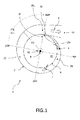
- Fig.1 shows an embodiment of a fluid pump 1 for conveying fluids F according to the present invention in a top view onto the rotation plane 41 of the impeller 4.
- the rotational axis R of the impeller 4 is aligned perpendicular to the rotational plane 41 of the impeller 4.
- the housing 2 further has a central inlet opening 31 (indicated by dashed circle in the middle of the impeller 4) for receiving the fluid F from the outside and an outlet opening 32 for discharging the fluid F.
- the housing 2 encloses an impeller 4, which rotates inside the housing 2 to pump the fluid F from the inlet opening 31 to the outlet opening 32.
- the fluid might be conveyed by blades (not shown here) arranged on top of the impeller 4 or might be conveyed through the impeller 4.
- the impeller 4 is driven by a motor assembly not shown here.
- the housing 2 provides a first conveying channel 21 located peripherally around the impeller 4 from a fluid entry point 21 a at 0° turn angle to a fluid exit point 21 c at 360° turn angle of the single turn volute being connected to the outlet opening 32, whereby the first conveying channel 21 has a first cross section area 21 F in radial direction RD perpendicular to the rotational plane 41 of the impeller 4.
- the edge of the tongue 23 facing towards the conveyed fluid F is located at the 0° turn angle.
- the fluid may exit the impeller 4 at any position between 0° turn angle and 360° turn angle, as indicated by the two bend arrows F extending from the inlet opening 31 towards the housing 2.
- a size of the first cross section area 21 F increases as a monotonic function of the turn angle between entry point 21 a and exit point 21 b, where the monotonic increasing function MIF (see Fig.5 ) has an average slope in a first turn angle interval 21 i from a first turn angle 21 b to the 360° turn angle at the exit point 21 b being smaller than the average slope in a second turn angel interval 21 s between 0° turn angle and the first turn angle 21 b to increase a velocity of the conveyed fluid F at least in an area 211 of the first conveying channel 21 assigned to the first turn angle interval 21 i.
- the monotonic increasing function MIF may have a concave shape in a first turn angle interval 21 i.
- the size of the cross section area might be zero or might be too small to be passed by the fluid or might provide a negligible pass rate for the fluid F not influencing the flow conditions within the housing 2.
- the fluid pump 1 shown in Fig.1 is a blood pump with blood as the pumped fluid F.
- Fig.2 shows an embodiment of a fluid pump 1 according to the present invention in a top view onto the rotation plane 41 of the impeller 4 with first and second conveying channels 21, 22.
- the rotational axis R of the impeller 4 is aligned perpendicular to the rotational plane 41 of the impeller 4.
- the fluid pump 1 shown here comprises the same components and areas as shown in Fig.1 , where the housing 2 is furthermore shaped to additionally provide a second conveying channel 22 around the impeller 4 (indicated as dashed circle around the impeller 4) being arranged between the first conveying channel 21 and the impeller 4.
- the second conveying channel 22 has a second cross section area 22F in radial direction perpendicular to the rotation plane 41 of the impeller 4 with a size at the fluid entry point 21 a of the single turn volute being large enough to significantly decrease friction forces between fluid F and housing 2 (wall of the first conveying channel 21). Therefore the size of the second cross section area 22F is larger than a predetermined minimum size required to achieve a significant decrease of the friction forces. Especially at the fluid entry point 21 a, where the volute tongue 23 is arranged, the size of the cross section area 21 F of the first conveying channel 21 is very small or zero causing the friction forces being larger than at other turn angles, where the first conveying channel 21 has larger cross section areas 21 F.
- the main contribution to the overall reduction of the friction force could be achieved by introducing the second conveying channel 22 with the second cross section area 22F.
- the size of the second cross section area 22F is constant from the fluid entry point 21 a at 0° turn angle to the fluid exit point 21 c at 360° turn angle of the single turn volute.
- the fluid pump 1 shown in Fig.2 is a blood pump with blood as the pumped fluid F.
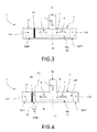
- Fig.3 shows a schematic view of the first cross section areas 21 F of the first conveying channel 21 at 180° turn angle and 360° turn angle in a side view of the fluid pump 1 of Fig.1 .
- the inlet opening 31 is arranged at a central position with respect to the impeller 4.
- the fluid F passes the inlet opening 31 parallel to the rotational axis R of the impeller 4 and is distributed through the impeller 4 (indicated by arrows F parallel to the radial direction RD) within the rotational plane 41 towards the first conveying channel 21.
- the volute tongue 23 is arranged in order to separate the fluid entry point 21 a from the fluid exit point 21 c connected to the outlet opening 32.
- the first cross section area 21 F of the first conveying channel 21 may have any suitable shape providing a conveying channel with similar dimensions parallel and perpendicular to the rotational axis R of the impeller 4.
- the first cross section area 21 F may be a rectangular, oval or circular area depending on the particular application and fluid.
- the first cross section area has a rectangular shape, in other embodiments the shape might be different, e.g. with rounded edges.
- the ratio between the sizes of the first cross section areas 21 at the turn angles of 360° (left hand side) and 180° (right hand side) might be less than 1.33.
- Fig.4 shows an schematic view of the first and second cross section areas 21 F, 22F of the first and second conveying channels 21, 22 at 180° turn angle (right hand side) and at 360° turn angle (left hand side) in a side view of the fluid pump 1 of Fig.2 .
- the second conveying channel 22 has a width 22W in radial direction RD of the impeller 4 of at least 5%, preferably at least 7%, more preferably at least 10%, of the radius 4r of the impeller 4 at least at the fluid entry point 21 a at 0° turn angle.
- the size of the second cross section area 22F at the entry point 21 a at 0° turn angle might be at least 10mm 2 .
- the size of the second cross section area at 22F the entry point 21 a is additionally below 20mm 2 .
- the second conveying channel 22 has a constant size and width 22W for the full turn of the single turn volute.
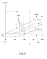
- Fig.5 shows different embodiments of the monotonic increasing function MIF according to the present invention ranging from 0° turn angle to 360° turn angle, which is divided into two parts, the second turn angel interval 21 s between 0° turn angle corresponding to the entry point 21 a and the first turn angle 21 b and followed by the first turn angle interval 21 i ranging from the first turn angle 21 b to the 360° turn angle corresponding with the exit point 21 c for the conveyed fluid out of the single turn volute.
- the size of the first cross section area 21 F continuously increases from 0° turn angle to 360° turn angle.
- the increase of the size of the first cross section area 21 F is described as a function of size depending on the turn angle ranging from 0° turn angle to 360° turn angle denotes here as monotonic increasing function MIF.
- the term "monotonic" denotes the fact that the size 21 F as a function of the turn angle will be constant or increases with the turn angle.
- a monotonic increasing function of the size 21 F over the turn angle does not comprise any intervals, where the size decreases when following the first conveying channel 21 from the fluid entry point 21 a at 0° turn angle to the fluid exit point 21 c at 360° turn angle.
- the monotonic increasing function MIF may be a straight line or has a concave shape between the first turn angle 21 b and 360° turn angle.
- the first turn angle 21 b is located between 180° and 270° turn angle to provide a turn angle interval 21 i of more than 90°.
- the term straight line denotes a line with a constant slope where a concave shape denotes a function, which second derivate is negative.
- a concave shape is the opposite shape to a convex shape.
- the first turn angle 21 b may be located at 180° turn angle or less.
- the first turn angle 21 b of the monotonic increasing function MIF represents an inflection point of the monotonic increasing function MIF, wherein the monotonic increasing function MIF may increases linearly between the 0° turn angle and the first turn angle 21 b or may have a convex shape between the 0° turn angle and the first turn angle 21 b.
- the monotonic increasing function MIF at 0° turn angle deviates from zero size by the size of the second conveying channel 22F at 0° turn angle (corresponds to the entry point 21 a).
- the size of the second conveying channel 22F is constant for all turn angles as indicated by the horizontal dashed line providing a constant positive offset 22F of the monotonic increasing function MIF.
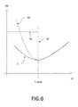
- Fig.6 shows the radially directed forces FR acting on the impeller 4 as a function of the flow rate Q of the conveyed fluid F for a fluid pump 1 according to the present invention in comparison to a corresponding curve PA for a fluid pump according to prior art, where the fluid pumps 1, PA are applied as a blood pumps with blood F as the fluid F.
- Both blood pumps 1, PA have layout points LP at 7 l/min, where the radially directed hydrodynamic forces FR acting on the impeller 4 have their minima.
- the radially directed hydrodynamic forces FR acting on the impeller 4 increase.
- Average volume flow-rates Q of blood for human beings are approximately at 5 l/min, where the value may be slightly different for males and females.
- the layout point LP shifted to higher flow rates Q corresponds to so-called oversized blood pumps providing an improved efficiency due to the reduction of the flow resistance caused by the viscosity of blood due to the increased inner dimensions of the conveying housing.
- blood pumps with a layout point of 5 l/min may have a cross section area at the exit point of approximately 30mm 2 , where such oversized blood pumps may have a cross section area at the exit point of approximately 60mm 2 .
- such oversized blood pumps 1, PA are mainly operated at flow rates Q below the layout point LP (at least more than 50% of the operational time), since the average volume flow rates of blood for human beings of 5 l/min is below the layout point LP.
- the blood pump 1 is operated nearly all the time (at least more than 90% of the operational time) at or below the layout point LP within the range of partial load PL.
- the radially directed forces FR will steeply increase especially for flow rates Q of the operational range of partial load PL, which would be disadvantageous for the bearing layout to bear the impeller, for the required bearing control and for non-disturbed long-time use.
- the slope of the increases of the radially directed forces FR acting on the impeller 4 depends on the shape of the housing 2 of the blood pump 1. Applying the design rules as specified for blood pumps 1 according to the present invention, the forces FR can be reduced significantly compared to common blood pumps PA in the flow rate Q for partial load PL. Therefore an oversized blood pump 1 according to the present invention provides an efficient fluid pump, where at least the hydrodynamic radially directed forces FR acting of the impeller 4 during operation at partial load PL are significantly smaller compared to fluid pumps PA according to the state of the art.
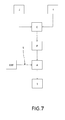
- Fig.7 shows an embodiment of the method to manufacture the fluid pump according to the present invention as shown in Fig.1 comprising the steps of establishing E a single turn volute of 360° turn angle within the housing 2 enclosing the impeller 4, providing P a first conveying channel 21 located peripherally around the impeller 4 from a fluid entry point 21 a at 0° turn angle to a fluid exit point 21 b at 360° turn angle of the single turn volute being connected to the outlet opening 32, where the first conveying channel 21 has a first cross section area 21 F in radial direction RD perpendicular to the rotational plane 41 of the impeller 4 and adapting A the first cross section area 21 F to have a size increasing as a monotonic function MIF of the turn angle between entry point 21 a and exit point 21 c, where the monotonic increasing function MIF has a concave shape in a first turn angle interval 21 i from a first turn angle 21 b to the 360° turn angle at the exit point 21 c to increase a velocity of the convey
- the method comprises the further step of providing a second conveying channel 22 in the single turn volute arranged around the impeller 4 and arranged between the first conveying channel 21 and the impeller 4, where the second conveying channel 22 has a second cross section area 22F in radial direction RD perpendicular to the rotation plane 41 of the impeller 4, where a size of the second cross section area 21 F at the fluid entry point 21 a of the single turn volute is larger than a predetermined minimum size.
- the friction forces caused by the viscosity of the conveyed fluid F are decreased in order to improve the pumping efficiency.
- the second cross section area 22F of the second conveying channel 22 is adapted to reduce the friction forces below a second threshold.
- Fig.8 shows an embodiment of the method to operate the fluid pump 1 according to the present invention.
- the fluid F enters the inlet opening 31 of the fluid pump 1, passes through the impeller 4 and enters at least the first conveying channel 21 and also the second conveying channel 22, if present.
- the fluid F is conveyed through the conveying channels 21, 22 into the area 211 of the first conveying channel 21 assigned to the first turn angle interval 21 i.
- the shape of the size of the first conveying channel 21 in accordance to the present invention leads to an increase S of the velocity of the conveyed fluid F from a first turn angle 21 b to the 360° turn angle at the exit point 21 c by a concave shape of the monotonic increasing function MIF within the first turn angle interval 21 i.
- the method enables to operate the fluid pump with an impeller, where at least the hydrodynamic forces acting of the impeller are smaller compared to fluid pumps according to the state of the art enabling to operate the fluid pump with lower the power consumption required for the bearings and/or enabling to simplify the bearing assembly of the fluid pump, e.g. requiring less bearing components.
- the fluid pump 1 is applied as a blood pump 1 with blood F as the fluid F and where the blood pump 1 has a layout point, at which a function of radially directed hydrodynamic forces acting on the impeller over a flow rate of pumped blood has a minimum and where the layout point is suitably adjusted to flow rates above the average volume flow of blood for human beings to be able to operate the blood pump mainly at partial load, the blood pump 1 is mainly operated at partial load.
Landscapes
- Health & Medical Sciences (AREA)
- Engineering & Computer Science (AREA)
- Heart & Thoracic Surgery (AREA)
- Mechanical Engineering (AREA)
- Cardiology (AREA)
- Hematology (AREA)
- Anesthesiology (AREA)
- Biomedical Technology (AREA)
- Life Sciences & Earth Sciences (AREA)
- Animal Behavior & Ethology (AREA)
- General Health & Medical Sciences (AREA)
- Public Health (AREA)
- Veterinary Medicine (AREA)
- General Engineering & Computer Science (AREA)
- Physics & Mathematics (AREA)
- Fluid Mechanics (AREA)
- Structures Of Non-Positive Displacement Pumps (AREA)
- External Artificial Organs (AREA)
Priority Applications (6)
| Application Number | Priority Date | Filing Date | Title |
|---|---|---|---|
| EP15193212.6A EP3165242B1 (de) | 2015-11-05 | 2015-11-05 | Flüssigkeitspumpe mit spiralförmigem gehäuse |
| CA3003205A CA3003205A1 (en) | 2015-11-05 | 2016-10-26 | Fluid pump with volute shaped housing |
| PCT/EP2016/075744 WO2017076708A1 (en) | 2015-11-05 | 2016-10-26 | Fluid pump with volute shaped housing |
| AU2016349649A AU2016349649B2 (en) | 2015-11-05 | 2016-10-26 | Fluid pump with volute shaped housing |
| CN201680064220.8A CN108289985B (zh) | 2015-11-05 | 2016-10-26 | 具有蜗形壳体的流体泵 |
| US15/771,166 US10668194B2 (en) | 2015-11-05 | 2016-10-26 | Fluid pump with volute shaped housing |
Applications Claiming Priority (1)
| Application Number | Priority Date | Filing Date | Title |
|---|---|---|---|
| EP15193212.6A EP3165242B1 (de) | 2015-11-05 | 2015-11-05 | Flüssigkeitspumpe mit spiralförmigem gehäuse |
Publications (2)
| Publication Number | Publication Date |
|---|---|
| EP3165242A1 true EP3165242A1 (de) | 2017-05-10 |
| EP3165242B1 EP3165242B1 (de) | 2019-05-15 |
Family
ID=54476804
Family Applications (1)
| Application Number | Title | Priority Date | Filing Date |
|---|---|---|---|
| EP15193212.6A Not-in-force EP3165242B1 (de) | 2015-11-05 | 2015-11-05 | Flüssigkeitspumpe mit spiralförmigem gehäuse |
Country Status (6)
| Country | Link |
|---|---|
| US (1) | US10668194B2 (de) |
| EP (1) | EP3165242B1 (de) |
| CN (1) | CN108289985B (de) |
| AU (1) | AU2016349649B2 (de) |
| CA (1) | CA3003205A1 (de) |
| WO (1) | WO2017076708A1 (de) |
Cited By (3)
| Publication number | Priority date | Publication date | Assignee | Title |
|---|---|---|---|---|
| US20220118243A1 (en) * | 2016-01-06 | 2022-04-21 | Bivacor Inc. | Heart pump |
| CN114483595A (zh) * | 2021-12-24 | 2022-05-13 | 江西耐普矿机股份有限公司 | 渣浆泵用准环形压水室水力设计方法和渣浆泵压水室 |
| CN115263810A (zh) * | 2022-08-10 | 2022-11-01 | 杭州老板电器股份有限公司 | 一种蜗壳、离心风机及厨房电器 |
Families Citing this family (3)
| Publication number | Priority date | Publication date | Assignee | Title |
|---|---|---|---|---|
| WO2021094145A1 (en) | 2019-11-12 | 2021-05-20 | Fresenius Medical Care Deutschland Gmbh | Blood treatment systems |
| CN114876830B (zh) * | 2022-04-26 | 2024-05-10 | 杭州老板电器股份有限公司 | 一种蜗壳、风机及油烟机 |
| KR20240068473A (ko) * | 2022-11-10 | 2024-05-17 | 한국생산기술연구원 | 단일유로 펌프의 설계 방법 |
Citations (6)
| Publication number | Priority date | Publication date | Assignee | Title |
|---|---|---|---|---|
| US4037984A (en) * | 1967-10-26 | 1977-07-26 | Bio-Medicus, Inc. | Pumping apparatus and process characterized by gentle operation |
| US20090234447A1 (en) * | 2007-04-30 | 2009-09-17 | Larose Jeffrey A | Centrifugal rotary blood pump |
| WO2014000753A1 (en) | 2012-06-28 | 2014-01-03 | Rheinisch-Westfälische Technische Hochschule Aachen | Centrifugal blood pump apparatus |
| US20140171727A1 (en) * | 2011-05-05 | 2014-06-19 | Berlin Heart GbmH | Blood pump |
| US20140205467A1 (en) * | 2013-01-24 | 2014-07-24 | Thoratec Corporation | Impeller position compensation using field oriented control |
| US20150005572A1 (en) * | 2011-10-13 | 2015-01-01 | Thoratec Corporation | Pump and Method For Mixed Flow Blood Pumping |
Family Cites Families (4)
| Publication number | Priority date | Publication date | Assignee | Title |
|---|---|---|---|---|
| US5928131A (en) * | 1997-11-26 | 1999-07-27 | Vascor, Inc. | Magnetically suspended fluid pump and control system |
| JP4759261B2 (ja) | 2004-12-16 | 2011-08-31 | テルモ株式会社 | 遠心式血液ポンプ装置 |
| US8517699B2 (en) * | 2008-12-16 | 2013-08-27 | Cleveland Clinic Foundation | Centrifugal pump with offset volute |
| US20140309481A1 (en) * | 2013-04-11 | 2014-10-16 | Thoratec Corporation | Rotary pump with levitated impeller having thrust bearing for improved startup |
-
2015
- 2015-11-05 EP EP15193212.6A patent/EP3165242B1/de not_active Not-in-force
-
2016
- 2016-10-26 CA CA3003205A patent/CA3003205A1/en not_active Abandoned
- 2016-10-26 WO PCT/EP2016/075744 patent/WO2017076708A1/en not_active Ceased
- 2016-10-26 US US15/771,166 patent/US10668194B2/en not_active Expired - Fee Related
- 2016-10-26 AU AU2016349649A patent/AU2016349649B2/en not_active Ceased
- 2016-10-26 CN CN201680064220.8A patent/CN108289985B/zh not_active Expired - Fee Related
Patent Citations (6)
| Publication number | Priority date | Publication date | Assignee | Title |
|---|---|---|---|---|
| US4037984A (en) * | 1967-10-26 | 1977-07-26 | Bio-Medicus, Inc. | Pumping apparatus and process characterized by gentle operation |
| US20090234447A1 (en) * | 2007-04-30 | 2009-09-17 | Larose Jeffrey A | Centrifugal rotary blood pump |
| US20140171727A1 (en) * | 2011-05-05 | 2014-06-19 | Berlin Heart GbmH | Blood pump |
| US20150005572A1 (en) * | 2011-10-13 | 2015-01-01 | Thoratec Corporation | Pump and Method For Mixed Flow Blood Pumping |
| WO2014000753A1 (en) | 2012-06-28 | 2014-01-03 | Rheinisch-Westfälische Technische Hochschule Aachen | Centrifugal blood pump apparatus |
| US20140205467A1 (en) * | 2013-01-24 | 2014-07-24 | Thoratec Corporation | Impeller position compensation using field oriented control |
Cited By (5)
| Publication number | Priority date | Publication date | Assignee | Title |
|---|---|---|---|---|
| US20220118243A1 (en) * | 2016-01-06 | 2022-04-21 | Bivacor Inc. | Heart pump |
| US11826558B2 (en) | 2016-01-06 | 2023-11-28 | Bivacor Inc. | Heart pump with impeller rotational speed control |
| US11833341B2 (en) * | 2016-01-06 | 2023-12-05 | Bivacor Inc. | Heart pump |
| CN114483595A (zh) * | 2021-12-24 | 2022-05-13 | 江西耐普矿机股份有限公司 | 渣浆泵用准环形压水室水力设计方法和渣浆泵压水室 |
| CN115263810A (zh) * | 2022-08-10 | 2022-11-01 | 杭州老板电器股份有限公司 | 一种蜗壳、离心风机及厨房电器 |
Also Published As
| Publication number | Publication date |
|---|---|
| CN108289985B (zh) | 2020-12-22 |
| US20180328382A1 (en) | 2018-11-15 |
| EP3165242B1 (de) | 2019-05-15 |
| AU2016349649B2 (en) | 2021-06-24 |
| CA3003205A1 (en) | 2017-05-11 |
| AU2016349649A1 (en) | 2018-05-17 |
| WO2017076708A1 (en) | 2017-05-11 |
| CN108289985A (zh) | 2018-07-17 |
| US10668194B2 (en) | 2020-06-02 |
Similar Documents
| Publication | Publication Date | Title |
|---|---|---|
| AU2016349649B2 (en) | Fluid pump with volute shaped housing | |
| EP3033120B1 (de) | Laufrad für axiale flusspumpe | |
| ES2975945T3 (es) | Microbomba encapsulada | |
| US10926012B2 (en) | Blood pump, preferably for assisting a heart | |
| EP3069740B1 (de) | Blutpumpe | |
| US9726195B2 (en) | Axial flow blood pump | |
| EP3636935B1 (de) | Zentrifugalblutpumpenlaufrad und -strömungsweg | |
| US10111994B2 (en) | Blood pump with separate mixed-flow and axial-flow impeller stages and multi-stage stators | |
| CN102935249B (zh) | 有多槽转子的轴流泵 | |
| EP4414020A2 (de) | Blutpumpe | |
| US20120134832A1 (en) | Blood pump with splitter impeller blades and splitter stator vanes and related methods | |
| EP3146987A1 (de) | Laufrad einer herzunterstützenden rotationsblutpumpe | |
| US11730946B2 (en) | Flow enhancement for circulatory support device | |
| HK40015801A (en) | Centrifugal blood pump impeller and flow path | |
| HK1236594B (en) | Centrifugal pump impeller |
Legal Events
| Date | Code | Title | Description |
|---|---|---|---|
| PUAI | Public reference made under article 153(3) epc to a published international application that has entered the european phase |
Free format text: ORIGINAL CODE: 0009012 |
|
| STAA | Information on the status of an ep patent application or granted ep patent |
Free format text: STATUS: THE APPLICATION HAS BEEN PUBLISHED |
|
| AK | Designated contracting states |
Kind code of ref document: A1 Designated state(s): AL AT BE BG CH CY CZ DE DK EE ES FI FR GB GR HR HU IE IS IT LI LT LU LV MC MK MT NL NO PL PT RO RS SE SI SK SM TR |
|
| AX | Request for extension of the european patent |
Extension state: BA ME |
|
| STAA | Information on the status of an ep patent application or granted ep patent |
Free format text: STATUS: REQUEST FOR EXAMINATION WAS MADE |
|
| 17P | Request for examination filed |
Effective date: 20171110 |
|
| RBV | Designated contracting states (corrected) |
Designated state(s): AL AT BE BG CH CY CZ DE DK EE ES FI FR GB GR HR HU IE IS IT LI LT LU LV MC MK MT NL NO PL PT RO RS SE SI SK SM TR |
|
| GRAP | Despatch of communication of intention to grant a patent |
Free format text: ORIGINAL CODE: EPIDOSNIGR1 |
|
| STAA | Information on the status of an ep patent application or granted ep patent |
Free format text: STATUS: GRANT OF PATENT IS INTENDED |
|
| RIC1 | Information provided on ipc code assigned before grant |
Ipc: F04D 29/44 20060101ALI20181025BHEP Ipc: A61M 1/12 20060101ALI20181025BHEP Ipc: A61M 1/10 20060101AFI20181025BHEP |
|
| INTG | Intention to grant announced |
Effective date: 20181122 |
|
| GRAS | Grant fee paid |
Free format text: ORIGINAL CODE: EPIDOSNIGR3 |
|
| GRAA | (expected) grant |
Free format text: ORIGINAL CODE: 0009210 |
|
| STAA | Information on the status of an ep patent application or granted ep patent |
Free format text: STATUS: THE PATENT HAS BEEN GRANTED |
|
| AK | Designated contracting states |
Kind code of ref document: B1 Designated state(s): AL AT BE BG CH CY CZ DE DK EE ES FI FR GB GR HR HU IE IS IT LI LT LU LV MC MK MT NL NO PL PT RO RS SE SI SK SM TR |
|
| REG | Reference to a national code |
Ref country code: CH Ref legal event code: EP |
|
| REG | Reference to a national code |
Ref country code: DE Ref legal event code: R096 Ref document number: 602015030268 Country of ref document: DE |
|
| REG | Reference to a national code |
Ref country code: IE Ref legal event code: FG4D |
|
| GRAL | Information related to payment of fee for publishing/printing deleted |
Free format text: ORIGINAL CODE: EPIDOSDIGR3 |
|
| GRAS | Grant fee paid |
Free format text: ORIGINAL CODE: EPIDOSNIGR3 |
|
| REG | Reference to a national code |
Ref country code: NL Ref legal event code: MP Effective date: 20190515 |
|
| REG | Reference to a national code |
Ref country code: LT Ref legal event code: MG4D |
|
| PG25 | Lapsed in a contracting state [announced via postgrant information from national office to epo] |
Ref country code: NO Free format text: LAPSE BECAUSE OF FAILURE TO SUBMIT A TRANSLATION OF THE DESCRIPTION OR TO PAY THE FEE WITHIN THE PRESCRIBED TIME-LIMIT Effective date: 20190815 Ref country code: AL Free format text: LAPSE BECAUSE OF FAILURE TO SUBMIT A TRANSLATION OF THE DESCRIPTION OR TO PAY THE FEE WITHIN THE PRESCRIBED TIME-LIMIT Effective date: 20190515 Ref country code: FI Free format text: LAPSE BECAUSE OF FAILURE TO SUBMIT A TRANSLATION OF THE DESCRIPTION OR TO PAY THE FEE WITHIN THE PRESCRIBED TIME-LIMIT Effective date: 20190515 Ref country code: SE Free format text: LAPSE BECAUSE OF FAILURE TO SUBMIT A TRANSLATION OF THE DESCRIPTION OR TO PAY THE FEE WITHIN THE PRESCRIBED TIME-LIMIT Effective date: 20190515 Ref country code: PT Free format text: LAPSE BECAUSE OF FAILURE TO SUBMIT A TRANSLATION OF THE DESCRIPTION OR TO PAY THE FEE WITHIN THE PRESCRIBED TIME-LIMIT Effective date: 20190915 Ref country code: HR Free format text: LAPSE BECAUSE OF FAILURE TO SUBMIT A TRANSLATION OF THE DESCRIPTION OR TO PAY THE FEE WITHIN THE PRESCRIBED TIME-LIMIT Effective date: 20190515 Ref country code: NL Free format text: LAPSE BECAUSE OF FAILURE TO SUBMIT A TRANSLATION OF THE DESCRIPTION OR TO PAY THE FEE WITHIN THE PRESCRIBED TIME-LIMIT Effective date: 20190515 Ref country code: ES Free format text: LAPSE BECAUSE OF FAILURE TO SUBMIT A TRANSLATION OF THE DESCRIPTION OR TO PAY THE FEE WITHIN THE PRESCRIBED TIME-LIMIT Effective date: 20190515 Ref country code: LT Free format text: LAPSE BECAUSE OF FAILURE TO SUBMIT A TRANSLATION OF THE DESCRIPTION OR TO PAY THE FEE WITHIN THE PRESCRIBED TIME-LIMIT Effective date: 20190515 |
|
| PG25 | Lapsed in a contracting state [announced via postgrant information from national office to epo] |
Ref country code: BG Free format text: LAPSE BECAUSE OF FAILURE TO SUBMIT A TRANSLATION OF THE DESCRIPTION OR TO PAY THE FEE WITHIN THE PRESCRIBED TIME-LIMIT Effective date: 20190815 Ref country code: RS Free format text: LAPSE BECAUSE OF FAILURE TO SUBMIT A TRANSLATION OF THE DESCRIPTION OR TO PAY THE FEE WITHIN THE PRESCRIBED TIME-LIMIT Effective date: 20190515 Ref country code: LV Free format text: LAPSE BECAUSE OF FAILURE TO SUBMIT A TRANSLATION OF THE DESCRIPTION OR TO PAY THE FEE WITHIN THE PRESCRIBED TIME-LIMIT Effective date: 20190515 Ref country code: GR Free format text: LAPSE BECAUSE OF FAILURE TO SUBMIT A TRANSLATION OF THE DESCRIPTION OR TO PAY THE FEE WITHIN THE PRESCRIBED TIME-LIMIT Effective date: 20190816 |
|
| REG | Reference to a national code |
Ref country code: AT Ref legal event code: MK05 Ref document number: 1132680 Country of ref document: AT Kind code of ref document: T Effective date: 20190515 |
|
| PG25 | Lapsed in a contracting state [announced via postgrant information from national office to epo] |
Ref country code: RO Free format text: LAPSE BECAUSE OF FAILURE TO SUBMIT A TRANSLATION OF THE DESCRIPTION OR TO PAY THE FEE WITHIN THE PRESCRIBED TIME-LIMIT Effective date: 20190515 Ref country code: SK Free format text: LAPSE BECAUSE OF FAILURE TO SUBMIT A TRANSLATION OF THE DESCRIPTION OR TO PAY THE FEE WITHIN THE PRESCRIBED TIME-LIMIT Effective date: 20190515 Ref country code: CZ Free format text: LAPSE BECAUSE OF FAILURE TO SUBMIT A TRANSLATION OF THE DESCRIPTION OR TO PAY THE FEE WITHIN THE PRESCRIBED TIME-LIMIT Effective date: 20190515 Ref country code: EE Free format text: LAPSE BECAUSE OF FAILURE TO SUBMIT A TRANSLATION OF THE DESCRIPTION OR TO PAY THE FEE WITHIN THE PRESCRIBED TIME-LIMIT Effective date: 20190515 Ref country code: AT Free format text: LAPSE BECAUSE OF FAILURE TO SUBMIT A TRANSLATION OF THE DESCRIPTION OR TO PAY THE FEE WITHIN THE PRESCRIBED TIME-LIMIT Effective date: 20190515 Ref country code: DK Free format text: LAPSE BECAUSE OF FAILURE TO SUBMIT A TRANSLATION OF THE DESCRIPTION OR TO PAY THE FEE WITHIN THE PRESCRIBED TIME-LIMIT Effective date: 20190515 |
|
| REG | Reference to a national code |
Ref country code: DE Ref legal event code: R097 Ref document number: 602015030268 Country of ref document: DE |
|
| PG25 | Lapsed in a contracting state [announced via postgrant information from national office to epo] |
Ref country code: IT Free format text: LAPSE BECAUSE OF FAILURE TO SUBMIT A TRANSLATION OF THE DESCRIPTION OR TO PAY THE FEE WITHIN THE PRESCRIBED TIME-LIMIT Effective date: 20190515 Ref country code: SM Free format text: LAPSE BECAUSE OF FAILURE TO SUBMIT A TRANSLATION OF THE DESCRIPTION OR TO PAY THE FEE WITHIN THE PRESCRIBED TIME-LIMIT Effective date: 20190515 |
|
| PLBE | No opposition filed within time limit |
Free format text: ORIGINAL CODE: 0009261 |
|
| STAA | Information on the status of an ep patent application or granted ep patent |
Free format text: STATUS: NO OPPOSITION FILED WITHIN TIME LIMIT |
|
| PG25 | Lapsed in a contracting state [announced via postgrant information from national office to epo] |
Ref country code: TR Free format text: LAPSE BECAUSE OF FAILURE TO SUBMIT A TRANSLATION OF THE DESCRIPTION OR TO PAY THE FEE WITHIN THE PRESCRIBED TIME-LIMIT Effective date: 20190515 |
|
| 26N | No opposition filed |
Effective date: 20200218 |
|
| PG25 | Lapsed in a contracting state [announced via postgrant information from national office to epo] |
Ref country code: PL Free format text: LAPSE BECAUSE OF FAILURE TO SUBMIT A TRANSLATION OF THE DESCRIPTION OR TO PAY THE FEE WITHIN THE PRESCRIBED TIME-LIMIT Effective date: 20190515 |
|
| PG25 | Lapsed in a contracting state [announced via postgrant information from national office to epo] |
Ref country code: SI Free format text: LAPSE BECAUSE OF FAILURE TO SUBMIT A TRANSLATION OF THE DESCRIPTION OR TO PAY THE FEE WITHIN THE PRESCRIBED TIME-LIMIT Effective date: 20190515 |
|
| REG | Reference to a national code |
Ref country code: CH Ref legal event code: PL |
|
| PG25 | Lapsed in a contracting state [announced via postgrant information from national office to epo] |
Ref country code: LU Free format text: LAPSE BECAUSE OF NON-PAYMENT OF DUE FEES Effective date: 20191105 Ref country code: CH Free format text: LAPSE BECAUSE OF NON-PAYMENT OF DUE FEES Effective date: 20191130 Ref country code: LI Free format text: LAPSE BECAUSE OF NON-PAYMENT OF DUE FEES Effective date: 20191130 Ref country code: MC Free format text: LAPSE BECAUSE OF FAILURE TO SUBMIT A TRANSLATION OF THE DESCRIPTION OR TO PAY THE FEE WITHIN THE PRESCRIBED TIME-LIMIT Effective date: 20190515 |
|
| REG | Reference to a national code |
Ref country code: BE Ref legal event code: MM Effective date: 20191130 |
|
| PG25 | Lapsed in a contracting state [announced via postgrant information from national office to epo] |
Ref country code: IE Free format text: LAPSE BECAUSE OF NON-PAYMENT OF DUE FEES Effective date: 20191105 |
|
| REG | Reference to a national code |
Ref country code: DE Ref legal event code: R079 Ref document number: 602015030268 Country of ref document: DE Free format text: PREVIOUS MAIN CLASS: A61M0001100000 Ipc: A61M0060000000 |
|
| PG25 | Lapsed in a contracting state [announced via postgrant information from national office to epo] |
Ref country code: BE Free format text: LAPSE BECAUSE OF NON-PAYMENT OF DUE FEES Effective date: 20191130 |
|
| PG25 | Lapsed in a contracting state [announced via postgrant information from national office to epo] |
Ref country code: CY Free format text: LAPSE BECAUSE OF FAILURE TO SUBMIT A TRANSLATION OF THE DESCRIPTION OR TO PAY THE FEE WITHIN THE PRESCRIBED TIME-LIMIT Effective date: 20190515 |
|
| PG25 | Lapsed in a contracting state [announced via postgrant information from national office to epo] |
Ref country code: IS Free format text: LAPSE BECAUSE OF FAILURE TO SUBMIT A TRANSLATION OF THE DESCRIPTION OR TO PAY THE FEE WITHIN THE PRESCRIBED TIME-LIMIT Effective date: 20190915 |
|
| PG25 | Lapsed in a contracting state [announced via postgrant information from national office to epo] |
Ref country code: HU Free format text: LAPSE BECAUSE OF FAILURE TO SUBMIT A TRANSLATION OF THE DESCRIPTION OR TO PAY THE FEE WITHIN THE PRESCRIBED TIME-LIMIT; INVALID AB INITIO Effective date: 20151105 Ref country code: MT Free format text: LAPSE BECAUSE OF FAILURE TO SUBMIT A TRANSLATION OF THE DESCRIPTION OR TO PAY THE FEE WITHIN THE PRESCRIBED TIME-LIMIT Effective date: 20190515 |
|
| REG | Reference to a national code |
Ref country code: DE Ref legal event code: R082 Ref document number: 602015030268 Country of ref document: DE Representative=s name: FARAGO PATENTANWAELTE GMBH, DE Ref country code: DE Ref legal event code: R082 Ref document number: 602015030268 Country of ref document: DE Representative=s name: FARAGO PATENTANWALTSGESELLSCHAFT MBH, DE |
|
| PG25 | Lapsed in a contracting state [announced via postgrant information from national office to epo] |
Ref country code: MK Free format text: LAPSE BECAUSE OF FAILURE TO SUBMIT A TRANSLATION OF THE DESCRIPTION OR TO PAY THE FEE WITHIN THE PRESCRIBED TIME-LIMIT Effective date: 20190515 |
|
| PGFP | Annual fee paid to national office [announced via postgrant information from national office to epo] |
Ref country code: GB Payment date: 20221125 Year of fee payment: 8 Ref country code: FR Payment date: 20221129 Year of fee payment: 8 Ref country code: DE Payment date: 20221128 Year of fee payment: 8 |
|
| REG | Reference to a national code |
Ref country code: DE Ref legal event code: R119 Ref document number: 602015030268 Country of ref document: DE |
|
| GBPC | Gb: european patent ceased through non-payment of renewal fee |
Effective date: 20231105 |
|
| PG25 | Lapsed in a contracting state [announced via postgrant information from national office to epo] |
Ref country code: DE Free format text: LAPSE BECAUSE OF NON-PAYMENT OF DUE FEES Effective date: 20240601 |
|
| PG25 | Lapsed in a contracting state [announced via postgrant information from national office to epo] |
Ref country code: GB Free format text: LAPSE BECAUSE OF NON-PAYMENT OF DUE FEES Effective date: 20231105 |
|
| PG25 | Lapsed in a contracting state [announced via postgrant information from national office to epo] |
Ref country code: FR Free format text: LAPSE BECAUSE OF NON-PAYMENT OF DUE FEES Effective date: 20231130 |
|
| PG25 | Lapsed in a contracting state [announced via postgrant information from national office to epo] |
Ref country code: GB Free format text: LAPSE BECAUSE OF NON-PAYMENT OF DUE FEES Effective date: 20231105 Ref country code: FR Free format text: LAPSE BECAUSE OF NON-PAYMENT OF DUE FEES Effective date: 20231130 Ref country code: DE Free format text: LAPSE BECAUSE OF NON-PAYMENT OF DUE FEES Effective date: 20240601 |