EP3165246B1 - Blutzirkulationssystem - Google Patents
Blutzirkulationssystem Download PDFInfo
- Publication number
- EP3165246B1 EP3165246B1 EP15832993.8A EP15832993A EP3165246B1 EP 3165246 B1 EP3165246 B1 EP 3165246B1 EP 15832993 A EP15832993 A EP 15832993A EP 3165246 B1 EP3165246 B1 EP 3165246B1
- Authority
- EP
- European Patent Office
- Prior art keywords
- blood
- blood transfer
- transfer rate
- control
- rate
- Prior art date
- Legal status (The legal status is an assumption and is not a legal conclusion. Google has not performed a legal analysis and makes no representation as to the accuracy of the status listed.)
- Active
Links
Images






Classifications
-
- A—HUMAN NECESSITIES
- A61—MEDICAL OR VETERINARY SCIENCE; HYGIENE
- A61M—DEVICES FOR INTRODUCING MEDIA INTO, OR ONTO, THE BODY; DEVICES FOR TRANSDUCING BODY MEDIA OR FOR TAKING MEDIA FROM THE BODY; DEVICES FOR PRODUCING OR ENDING SLEEP OR STUPOR
- A61M1/00—Suction or pumping devices for medical purposes; Devices for carrying-off, for treatment of, or for carrying-over, body-liquids; Drainage systems
- A61M1/36—Other treatment of blood in a by-pass of the natural circulatory system, e.g. temperature adaptation, irradiation ; Extra-corporeal blood circuits
- A61M1/3621—Extra-corporeal blood circuits
- A61M1/3666—Cardiac or cardiopulmonary bypass, e.g. heart-lung machines
-
- A—HUMAN NECESSITIES
- A61—MEDICAL OR VETERINARY SCIENCE; HYGIENE
- A61M—DEVICES FOR INTRODUCING MEDIA INTO, OR ONTO, THE BODY; DEVICES FOR TRANSDUCING BODY MEDIA OR FOR TAKING MEDIA FROM THE BODY; DEVICES FOR PRODUCING OR ENDING SLEEP OR STUPOR
- A61M1/00—Suction or pumping devices for medical purposes; Devices for carrying-off, for treatment of, or for carrying-over, body-liquids; Drainage systems
- A61M1/14—Dialysis systems; Artificial kidneys; Blood oxygenators ; Reciprocating systems for treatment of body fluids, e.g. single needle systems for hemofiltration or pheresis
- A61M1/16—Dialysis systems; Artificial kidneys; Blood oxygenators ; Reciprocating systems for treatment of body fluids, e.g. single needle systems for hemofiltration or pheresis with membranes
- A61M1/1601—Control or regulation
- A61M1/1603—Regulation parameters
-
- A—HUMAN NECESSITIES
- A61—MEDICAL OR VETERINARY SCIENCE; HYGIENE
- A61M—DEVICES FOR INTRODUCING MEDIA INTO, OR ONTO, THE BODY; DEVICES FOR TRANSDUCING BODY MEDIA OR FOR TAKING MEDIA FROM THE BODY; DEVICES FOR PRODUCING OR ENDING SLEEP OR STUPOR
- A61M1/00—Suction or pumping devices for medical purposes; Devices for carrying-off, for treatment of, or for carrying-over, body-liquids; Drainage systems
- A61M1/14—Dialysis systems; Artificial kidneys; Blood oxygenators ; Reciprocating systems for treatment of body fluids, e.g. single needle systems for hemofiltration or pheresis
- A61M1/16—Dialysis systems; Artificial kidneys; Blood oxygenators ; Reciprocating systems for treatment of body fluids, e.g. single needle systems for hemofiltration or pheresis with membranes
- A61M1/1621—Constructional aspects thereof
- A61M1/1629—Constructional aspects thereof with integral heat exchanger
-
- A—HUMAN NECESSITIES
- A61—MEDICAL OR VETERINARY SCIENCE; HYGIENE
- A61M—DEVICES FOR INTRODUCING MEDIA INTO, OR ONTO, THE BODY; DEVICES FOR TRANSDUCING BODY MEDIA OR FOR TAKING MEDIA FROM THE BODY; DEVICES FOR PRODUCING OR ENDING SLEEP OR STUPOR
- A61M1/00—Suction or pumping devices for medical purposes; Devices for carrying-off, for treatment of, or for carrying-over, body-liquids; Drainage systems
- A61M1/14—Dialysis systems; Artificial kidneys; Blood oxygenators ; Reciprocating systems for treatment of body fluids, e.g. single needle systems for hemofiltration or pheresis
- A61M1/16—Dialysis systems; Artificial kidneys; Blood oxygenators ; Reciprocating systems for treatment of body fluids, e.g. single needle systems for hemofiltration or pheresis with membranes
- A61M1/1698—Blood oxygenators with or without heat-exchangers
-
- A—HUMAN NECESSITIES
- A61—MEDICAL OR VETERINARY SCIENCE; HYGIENE
- A61M—DEVICES FOR INTRODUCING MEDIA INTO, OR ONTO, THE BODY; DEVICES FOR TRANSDUCING BODY MEDIA OR FOR TAKING MEDIA FROM THE BODY; DEVICES FOR PRODUCING OR ENDING SLEEP OR STUPOR
- A61M1/00—Suction or pumping devices for medical purposes; Devices for carrying-off, for treatment of, or for carrying-over, body-liquids; Drainage systems
- A61M1/36—Other treatment of blood in a by-pass of the natural circulatory system, e.g. temperature adaptation, irradiation ; Extra-corporeal blood circuits
- A61M1/3621—Extra-corporeal blood circuits
- A61M1/3623—Means for actively controlling temperature of blood
-
- A—HUMAN NECESSITIES
- A61—MEDICAL OR VETERINARY SCIENCE; HYGIENE
- A61M—DEVICES FOR INTRODUCING MEDIA INTO, OR ONTO, THE BODY; DEVICES FOR TRANSDUCING BODY MEDIA OR FOR TAKING MEDIA FROM THE BODY; DEVICES FOR PRODUCING OR ENDING SLEEP OR STUPOR
- A61M1/00—Suction or pumping devices for medical purposes; Devices for carrying-off, for treatment of, or for carrying-over, body-liquids; Drainage systems
- A61M1/36—Other treatment of blood in a by-pass of the natural circulatory system, e.g. temperature adaptation, irradiation ; Extra-corporeal blood circuits
- A61M1/3621—Extra-corporeal blood circuits
- A61M1/3624—Level detectors; Level control
-
- A—HUMAN NECESSITIES
- A61—MEDICAL OR VETERINARY SCIENCE; HYGIENE
- A61M—DEVICES FOR INTRODUCING MEDIA INTO, OR ONTO, THE BODY; DEVICES FOR TRANSDUCING BODY MEDIA OR FOR TAKING MEDIA FROM THE BODY; DEVICES FOR PRODUCING OR ENDING SLEEP OR STUPOR
- A61M1/00—Suction or pumping devices for medical purposes; Devices for carrying-off, for treatment of, or for carrying-over, body-liquids; Drainage systems
- A61M1/36—Other treatment of blood in a by-pass of the natural circulatory system, e.g. temperature adaptation, irradiation ; Extra-corporeal blood circuits
- A61M1/3621—Extra-corporeal blood circuits
- A61M1/3639—Blood pressure control, pressure transducers specially adapted therefor
-
- A—HUMAN NECESSITIES
- A61—MEDICAL OR VETERINARY SCIENCE; HYGIENE
- A61M—DEVICES FOR INTRODUCING MEDIA INTO, OR ONTO, THE BODY; DEVICES FOR TRANSDUCING BODY MEDIA OR FOR TAKING MEDIA FROM THE BODY; DEVICES FOR PRODUCING OR ENDING SLEEP OR STUPOR
- A61M60/00—Blood pumps; Devices for mechanical circulatory actuation; Balloon pumps for circulatory assistance
- A61M60/10—Location thereof with respect to the patient's body
- A61M60/104—Extracorporeal pumps, i.e. the blood being pumped outside the patient's body
-
- A—HUMAN NECESSITIES
- A61—MEDICAL OR VETERINARY SCIENCE; HYGIENE
- A61M—DEVICES FOR INTRODUCING MEDIA INTO, OR ONTO, THE BODY; DEVICES FOR TRANSDUCING BODY MEDIA OR FOR TAKING MEDIA FROM THE BODY; DEVICES FOR PRODUCING OR ENDING SLEEP OR STUPOR
- A61M60/00—Blood pumps; Devices for mechanical circulatory actuation; Balloon pumps for circulatory assistance
- A61M60/10—Location thereof with respect to the patient's body
- A61M60/104—Extracorporeal pumps, i.e. the blood being pumped outside the patient's body
- A61M60/109—Extracorporeal pumps, i.e. the blood being pumped outside the patient's body incorporated within extracorporeal blood circuits or systems
- A61M60/113—Extracorporeal pumps, i.e. the blood being pumped outside the patient's body incorporated within extracorporeal blood circuits or systems in other functional devices, e.g. dialysers or heart-lung machines
-
- A—HUMAN NECESSITIES
- A61—MEDICAL OR VETERINARY SCIENCE; HYGIENE
- A61M—DEVICES FOR INTRODUCING MEDIA INTO, OR ONTO, THE BODY; DEVICES FOR TRANSDUCING BODY MEDIA OR FOR TAKING MEDIA FROM THE BODY; DEVICES FOR PRODUCING OR ENDING SLEEP OR STUPOR
- A61M60/00—Blood pumps; Devices for mechanical circulatory actuation; Balloon pumps for circulatory assistance
- A61M60/20—Type thereof
- A61M60/205—Non-positive displacement blood pumps
- A61M60/216—Non-positive displacement blood pumps including a rotating member acting on the blood, e.g. impeller
- A61M60/226—Non-positive displacement blood pumps including a rotating member acting on the blood, e.g. impeller the blood flow through the rotating member having mainly radial components
- A61M60/232—Centrifugal pumps
-
- A—HUMAN NECESSITIES
- A61—MEDICAL OR VETERINARY SCIENCE; HYGIENE
- A61M—DEVICES FOR INTRODUCING MEDIA INTO, OR ONTO, THE BODY; DEVICES FOR TRANSDUCING BODY MEDIA OR FOR TAKING MEDIA FROM THE BODY; DEVICES FOR PRODUCING OR ENDING SLEEP OR STUPOR
- A61M60/00—Blood pumps; Devices for mechanical circulatory actuation; Balloon pumps for circulatory assistance
- A61M60/20—Type thereof
- A61M60/247—Positive displacement blood pumps
- A61M60/253—Positive displacement blood pumps including a displacement member directly acting on the blood
- A61M60/268—Positive displacement blood pumps including a displacement member directly acting on the blood the displacement member being flexible, e.g. membranes, diaphragms or bladders
- A61M60/279—Peristaltic pumps, e.g. roller pumps
-
- A—HUMAN NECESSITIES
- A61—MEDICAL OR VETERINARY SCIENCE; HYGIENE
- A61M—DEVICES FOR INTRODUCING MEDIA INTO, OR ONTO, THE BODY; DEVICES FOR TRANSDUCING BODY MEDIA OR FOR TAKING MEDIA FROM THE BODY; DEVICES FOR PRODUCING OR ENDING SLEEP OR STUPOR
- A61M60/00—Blood pumps; Devices for mechanical circulatory actuation; Balloon pumps for circulatory assistance
- A61M60/30—Medical purposes thereof other than the enhancement of the cardiac output
- A61M60/36—Medical purposes thereof other than the enhancement of the cardiac output for specific blood treatment; for specific therapy
- A61M60/38—Blood oxygenation
-
- A—HUMAN NECESSITIES
- A61—MEDICAL OR VETERINARY SCIENCE; HYGIENE
- A61M—DEVICES FOR INTRODUCING MEDIA INTO, OR ONTO, THE BODY; DEVICES FOR TRANSDUCING BODY MEDIA OR FOR TAKING MEDIA FROM THE BODY; DEVICES FOR PRODUCING OR ENDING SLEEP OR STUPOR
- A61M60/00—Blood pumps; Devices for mechanical circulatory actuation; Balloon pumps for circulatory assistance
- A61M60/40—Details relating to driving
- A61M60/403—Details relating to driving for non-positive displacement blood pumps
- A61M60/408—Details relating to driving for non-positive displacement blood pumps the force acting on the blood contacting member being mechanical, e.g. transmitted by a shaft or cable
- A61M60/411—Details relating to driving for non-positive displacement blood pumps the force acting on the blood contacting member being mechanical, e.g. transmitted by a shaft or cable generated by an electromotor
-
- A—HUMAN NECESSITIES
- A61—MEDICAL OR VETERINARY SCIENCE; HYGIENE
- A61M—DEVICES FOR INTRODUCING MEDIA INTO, OR ONTO, THE BODY; DEVICES FOR TRANSDUCING BODY MEDIA OR FOR TAKING MEDIA FROM THE BODY; DEVICES FOR PRODUCING OR ENDING SLEEP OR STUPOR
- A61M60/00—Blood pumps; Devices for mechanical circulatory actuation; Balloon pumps for circulatory assistance
- A61M60/40—Details relating to driving
- A61M60/424—Details relating to driving for positive displacement blood pumps
- A61M60/427—Details relating to driving for positive displacement blood pumps the force acting on the blood contacting member being hydraulic or pneumatic
-
- A—HUMAN NECESSITIES
- A61—MEDICAL OR VETERINARY SCIENCE; HYGIENE
- A61M—DEVICES FOR INTRODUCING MEDIA INTO, OR ONTO, THE BODY; DEVICES FOR TRANSDUCING BODY MEDIA OR FOR TAKING MEDIA FROM THE BODY; DEVICES FOR PRODUCING OR ENDING SLEEP OR STUPOR
- A61M60/00—Blood pumps; Devices for mechanical circulatory actuation; Balloon pumps for circulatory assistance
- A61M60/50—Details relating to control
- A61M60/508—Electronic control means, e.g. for feedback regulation
- A61M60/515—Regulation using real-time patient data
- A61M60/523—Regulation using real-time patient data using blood flow data, e.g. from blood flow transducers
-
- A—HUMAN NECESSITIES
- A61—MEDICAL OR VETERINARY SCIENCE; HYGIENE
- A61M—DEVICES FOR INTRODUCING MEDIA INTO, OR ONTO, THE BODY; DEVICES FOR TRANSDUCING BODY MEDIA OR FOR TAKING MEDIA FROM THE BODY; DEVICES FOR PRODUCING OR ENDING SLEEP OR STUPOR
- A61M60/00—Blood pumps; Devices for mechanical circulatory actuation; Balloon pumps for circulatory assistance
- A61M60/50—Details relating to control
- A61M60/508—Electronic control means, e.g. for feedback regulation
- A61M60/538—Regulation using real-time blood pump operational parameter data, e.g. motor current
- A61M60/546—Regulation using real-time blood pump operational parameter data, e.g. motor current of blood flow, e.g. by adapting rotor speed
-
- A—HUMAN NECESSITIES
- A61—MEDICAL OR VETERINARY SCIENCE; HYGIENE
- A61M—DEVICES FOR INTRODUCING MEDIA INTO, OR ONTO, THE BODY; DEVICES FOR TRANSDUCING BODY MEDIA OR FOR TAKING MEDIA FROM THE BODY; DEVICES FOR PRODUCING OR ENDING SLEEP OR STUPOR
- A61M2205/00—General characteristics of the apparatus
- A61M2205/18—General characteristics of the apparatus with alarm
-
- A—HUMAN NECESSITIES
- A61—MEDICAL OR VETERINARY SCIENCE; HYGIENE
- A61M—DEVICES FOR INTRODUCING MEDIA INTO, OR ONTO, THE BODY; DEVICES FOR TRANSDUCING BODY MEDIA OR FOR TAKING MEDIA FROM THE BODY; DEVICES FOR PRODUCING OR ENDING SLEEP OR STUPOR
- A61M2205/00—General characteristics of the apparatus
- A61M2205/33—Controlling, regulating or measuring
- A61M2205/3303—Using a biosensor
-
- A—HUMAN NECESSITIES
- A61—MEDICAL OR VETERINARY SCIENCE; HYGIENE
- A61M—DEVICES FOR INTRODUCING MEDIA INTO, OR ONTO, THE BODY; DEVICES FOR TRANSDUCING BODY MEDIA OR FOR TAKING MEDIA FROM THE BODY; DEVICES FOR PRODUCING OR ENDING SLEEP OR STUPOR
- A61M2205/00—General characteristics of the apparatus
- A61M2205/33—Controlling, regulating or measuring
- A61M2205/3306—Optical measuring means
-
- A—HUMAN NECESSITIES
- A61—MEDICAL OR VETERINARY SCIENCE; HYGIENE
- A61M—DEVICES FOR INTRODUCING MEDIA INTO, OR ONTO, THE BODY; DEVICES FOR TRANSDUCING BODY MEDIA OR FOR TAKING MEDIA FROM THE BODY; DEVICES FOR PRODUCING OR ENDING SLEEP OR STUPOR
- A61M2205/00—General characteristics of the apparatus
- A61M2205/33—Controlling, regulating or measuring
- A61M2205/3331—Pressure; Flow
- A61M2205/3334—Measuring or controlling the flow rate
-
- A—HUMAN NECESSITIES
- A61—MEDICAL OR VETERINARY SCIENCE; HYGIENE
- A61M—DEVICES FOR INTRODUCING MEDIA INTO, OR ONTO, THE BODY; DEVICES FOR TRANSDUCING BODY MEDIA OR FOR TAKING MEDIA FROM THE BODY; DEVICES FOR PRODUCING OR ENDING SLEEP OR STUPOR
- A61M2205/00—General characteristics of the apparatus
- A61M2205/33—Controlling, regulating or measuring
- A61M2205/3365—Rotational speed
-
- A—HUMAN NECESSITIES
- A61—MEDICAL OR VETERINARY SCIENCE; HYGIENE
- A61M—DEVICES FOR INTRODUCING MEDIA INTO, OR ONTO, THE BODY; DEVICES FOR TRANSDUCING BODY MEDIA OR FOR TAKING MEDIA FROM THE BODY; DEVICES FOR PRODUCING OR ENDING SLEEP OR STUPOR
- A61M2205/00—General characteristics of the apparatus
- A61M2205/33—Controlling, regulating or measuring
- A61M2205/3375—Acoustical, e.g. ultrasonic, measuring means
-
- A—HUMAN NECESSITIES
- A61—MEDICAL OR VETERINARY SCIENCE; HYGIENE
- A61M—DEVICES FOR INTRODUCING MEDIA INTO, OR ONTO, THE BODY; DEVICES FOR TRANSDUCING BODY MEDIA OR FOR TAKING MEDIA FROM THE BODY; DEVICES FOR PRODUCING OR ENDING SLEEP OR STUPOR
- A61M2205/00—General characteristics of the apparatus
- A61M2205/50—General characteristics of the apparatus with microprocessors or computers
-
- A—HUMAN NECESSITIES
- A61—MEDICAL OR VETERINARY SCIENCE; HYGIENE
- A61M—DEVICES FOR INTRODUCING MEDIA INTO, OR ONTO, THE BODY; DEVICES FOR TRANSDUCING BODY MEDIA OR FOR TAKING MEDIA FROM THE BODY; DEVICES FOR PRODUCING OR ENDING SLEEP OR STUPOR
- A61M2205/00—General characteristics of the apparatus
- A61M2205/50—General characteristics of the apparatus with microprocessors or computers
- A61M2205/502—User interfaces, e.g. screens or keyboards
Definitions
- the present invention relates to a blood circulation system that circulates removed blood via a blood transfer pump.
- an artificial heart and lung and a blood circulation system for adjunctively circulating blood are widely used as necessary when a heart is stopped or is approximately stopped during or after surgery such as cardiac surgery.
- an artificial heart and lung apparatus (blood circulation system) 500 equipped with an artificial heart and lung in the related art includes a blood removal line 501; a reservoir 502; a blood line 503; a blood transfer line 504; a first blood transfer line 505; an artificial lung 506; and a second blood transfer line 507.
- the blood removal line 501 transfers blood, which has been received from a vein of a patient (human body) P, to the reservoir 502.
- the blood removal line 501 is a tube formed of resin such as polyvinyl chloride.
- the reservoir 502 includes a tank therein, and temporarily stores the transferred blood.
- the blood transfer pump 504 transfers the blood stored in the reservoir 502 to the artificial lung 506 via the blood line 503 through which the reservoir 502 is connected to the blood transfer pump 504, and via the first blood transfer line 505 through which the blood transfer pump 504 is connected to the artificial lung 506.
- a roller pump or a centrifugal pump is used as the blood transfer pump 504.
- the blood transfer pump 504 is controlled by a signal output from a blood transfer pump control unit 540.
- the artificial lung 506 includes a hollow fiber membrane, a flat membrane, or the like having good gas permeability, and has the function of discharging carbon dioxide from and adding oxygen to blood.
- the second blood transfer line 507 receives the blood, from which carbon dioxide has been discharged and to which oxygen has been added by the artificial lung 506, and transfers the blood to an artery of the patient P.
- Advanced knowledge and techniques are required to operate the artificial heart and lung apparatus 500 with such a configuration.
- a clinical engineer adjusts a blood flow rate via a manual operation according to a doctor's instructions.
- the clinical engineer When adjusting the blood flow rate via a manual operation, the clinical engineer is required to adjust a blood flow rate in the blood removal line 501 by pinching the blood removal line 501 with a forceps while confirming the degree of removal of blood or an arterial pressure of the patient.
- Patent Document 1 discloses technology to adjust a blood removal rate in which the blood removal line 501 is pinched and deformed to accurately and simply adjust the blood removal rate via an artificial heart and lung apparatus.
- the artificial heart and lung apparatus disclosed in Patent Document 1 pinches and deforms the blood removal line 501 by operating a blood removal regulator 521, which includes a clamper formed of a pair of clamp members and a servo motor, via a blood removal regulator operation unit 520.
- Patent Document 2 discloses technology in which a blood removal regulator control unit is linked with a blood transfer regulator control unit, a blood removal rate and a blood transfer rate are simultaneously controlled via operation of one of the control units, and thus a blood flow rate of an artificial heart and lung apparatus is efficiently adjusted.
- JP 2006 325750 discloses providing a blood circulation system capable of controlling the pressure and flow rate of blood to be sent out to be within a prescribed range as needed in the case of supplying the blood by a centrifugal pump and reducing burdens on a patient by stably supplying the blood, and its controller.
- the controller of the blood circulation system comprises a blood circulation path freely connectable to the patient and the centrifugal pump for using the blood circulation path as an auxiliary circulation path or circulating the blood between a human body and a pump oxygenerator is provided with a control part for adjusting the pressure of the blood by controlling the increase/decrease of the speed of revolution of the centrifugal pump on the basis of a pressure measurement value input from a blood pressure measuring means installable to the blood circulation path or the human body.
- WO 2012/141756 discloses allowing a surgeon to control the heart-lung machine during heart surgery through voice commands.
- the control unit of the heart-lung machine is able to recognize the commands through the speech recognition software and it translates into electro-digital signals. This signals travels to the main-software that transform into electro-magnetic signals to the heart-lung machine executive parts. These parts are solenoid -actuators, solenoid valves, switches, and any electro-magnetic system that transform this signal into mechanical work.
- the solenoid actuators and valves are able to activate mechanical clamps, flow controllers, sensors, but not limited to those parts.
- the safety software ensures the command received is safe to be performed.
- the safety software analyses bv comparison of the real time data and set-point values (flow, Sv02, Art Pressure, temperature, minimum volume in the reservoir and others.
- the safety software also is able to activate flow controller and clamps during routine control.
- EP 2711037 discloses a perfusion system that is easy to set-up, use and monitor during a bypass procedure.
- the disclosure pertains to a perfusion system in which at least some of the disposable components used with the perfusion system are configured to be able to communicate set-up and/or operational parameters to the perfusion system in order to unlock further functionality within the perfusion system.
- the amount of blood to be removed may change depending on surgical situations, and a blood circulation system which is capable of stably transferring blood even if a blood removal rate changes significantly is required.
- the blood circulation system capable of stably transferring blood is desirably capable of efficiently circulating blood.
- the present invention is made in light of this problem, and an object of the present invention is to provide a blood circulation system that is capable of stably transferring blood and efficiently circulating blood.
- the present invention proposes the following means.
- a blood circulation system that can be connected to a human body, and transfers removed blood to the human body via a blood transfer pump, includes: the blood transfer pump; a blood removal line through which removed blood flows to the blood transfer pump; a blood transfer line that transfers blood, which is sent from the blood transfer pump, to the human body; blood removal rate measurement means that is provided in the blood removal line; a control unit that performs the linked control of the blood transfer pump in correspondence with a blood removal rate measured by the blood removal rate measurement means such that a blood transfer rate of the blood transfer pump is in a specific range with respect to the blood removal rate; and blood transfer rate instruction means for instructing a target blood transfer rate of the blood transfer pump in normal control in which the blood transfer pump transfers blood independently from the blood removal rate.
- the blood transfer rate instruction means includes a blood transfer rate adjustment unit.
- the blood transfer rate adjustment unit includes an operation amount input unit to which an operation amount from an arbitrary position can be input, and which outputs a pulse signal according to the input operation amount, and a counter that adds and subtracts pulse signals output from the operation amount input unit, and outputs a resultant as blood transfer rate adjustment data, and the counter performs a counting operation with respect to the position of the operation amount input unit when blood transfer control transitions to the normal control.
- control unit performs the linked control of the blood transfer pump in correspondence with the blood removal rate such that the blood transfer rate is in a specific range with respect to the blood removal rate. Therefore, even if the blood removal rate changes, it is possible to stably circulate blood.
- the position of the blood transfer rate adjustment unit when transitioning to the normal control is used as a reference. Accordingly, in a case where an operation amount such as a volume is mechanically set, typically, it is difficult to automatically reset a reference position. For this reason, in the blood circulation system, in a case where the linked control is not continuously performed, and the blood transfer control transitions to the normal control, the volume or the like is desirably manually reset (for example, reset to a reference position such as zero). In contrast, in the blood transfer rate adjustment unit of the invention, it is possible to eliminate the labor and time required to manually reset a volume or the like.
- the blood circulation system is capable of efficiently adjusting a blood transfer flow in the normal control without stopping.
- the blood transfer rate in the linked control is significantly smaller than a blood transfer rate that is set by the blood transfer rate adjustment unit in the normal control before the blood transfer control transitions to the linked control, it is possible to prevent blood from being transferred at the previous blood transfer rate, which has been set by the blood transfer rate adjustment unit, after the blood transfer control transitions to the normal control, and it is possible to stably circulate blood.
- the blood removal line represents a blood line among blood lines of the blood circulation system which is formed such that blood removed from the human body flows through the blood line toward the blood transfer pump. More specifically, the blood removal line represents a blood line leading toward a reservoir.
- the blood transfer line represents a blood line leading toward the human body from the blood transfer pump.
- a blood line which is positioned on the downstream side of a portion (for example, reservoir) in which blood opens to a space and in which there is no normal continuity of a blood flow rate, may not represent the blood removal line or the blood transfer line.
- a blood line may indicate a portion of the blood removal line and the blood transfer line.
- the linked control implies that the transferring of blood performed by the blood transfer pump is controlled while being linked with the blood removal rate.
- the linked control implies that the blood transfer rate of the blood transfer pump is controlled to be in a specific range with respect to the blood removal rate.
- the fact that the blood transfer rate is in a specific range with respect to the blood removal rate implies that the blood transfer rate is in a range of conditions which is set in advance with respect to the blood removal rate.
- the specific range can be represented by a difference in flow rate (for example, an upper limit or lower limit difference in flow rate) with respect to the blood removal rate.
- the synchronization of the blood transfer rate with the blood removal rate implies that the blood transfer rate of the blood transfer pump is set to be equal to the blood removal rate, and includes a case in which the blood transfer rate exactly coincides with blood removal rate, and a case in which the blood transfer rate substantially coincides with the blood removal rate. That is, errors caused by a time lag of a control signal output to the blood transfer pump or a response time of the blood transfer pump are allowed.
- the synchronization includes a case in which the same amount of blood as the amount of removed blood is transferred by the blood transfer pump when the transferring of blood is delayed by an amount of time set in advance.
- the normal control implies that the blood transfer rate of the blood transfer pump is controlled independently from the blood removal rate, and implies that the blood transfer rate is controlled while not being linked with the blood removal rate.
- the normal control includes a case in which control is performed according to an instruction regarding a blood transfer rate which is given by a manual operation, and a case in which control is performed according to data (including data stored in the storage means) set in advance.
- the blood removal rate measurement means includes measurement means for measuring a blood removal rate, and includes measurement means for measuring various blood removal rate parameters for specifying a blood removal rate.
- the blood removal rate parameters are parameters which change in correspondence with a blood removal rate, and include a blood removal rate.
- the blood removal rate parameters include various parameters for specifying a blood removal rate, for example, the flow speed of removed blood in a case where a cross-sectional flow path area of the blood removal line is already known, and a parameter (for example, a change in ultrasonic wave frequency) for specifying the flow speed.
- the fact that the blood transfer rate of the blood transfer pump is set to be in a specific range of blood removal rates measured by the blood removal rate measurement means includes a case in which the blood removal rate is not calculated, and according to measured values of the blood removal rate parameters, the blood transfer pump is directly controlled in order for the blood transfer rate to be in a specific range.
- an operation amount input unit to which an operation amount from an arbitrary position can be input, and which outputs a pulse signal according to an input operation amount, is considered to have the following configuration.
- An encoder in which an instruction output and a circumferential position (rotational position) are not in a fixed one-to-one relationship and which is capable of having an arbitrary position as a reference (zero) for use in inputting an operation amount, regardless of the position (including a rotational angle, a circumferential position, or the like) of a latch or the like, corresponds to the operation amount input unit.
- the blood transfer rate adjustment unit may not include an encoder.
- the position of the input unit implies the circumferential position (rotational angle) of a rotary latch.
- the input unit includes a pair of (+) press switch and (-) press switch, and increases or decreases an operation amount according to the number of presses thereof, the position of the input unit implies the number of presses of a press switch.
- the blood transfer rate instruction means includes a linked blood transfer rate storage unit that stores data relating to a linked blood transfer rate when the blood transfer control transitions from the linked control to the normal control.
- the control unit controls the blood transfer rate according to the data relating to a linked blood transfer rate which is stored in the linked blood transfer rate storage unit.
- the blood transfer rate instruction means includes the linked blood transfer rate storage unit, and the linked blood transfer rate storage unit is capable of storing the data relating to a linked blood transfer rate when the blood transfer control transitions from the linked control to the normal control. Accordingly, in a case where the blood transfer control transitions from the linked control to the normal control, the blood transfer rate instruction means is capable of controlling the blood transfer rate according to the data relating to a linked blood transfer rate which is stored in the linked blood transfer rate storage unit.
- the blood transfer rate adjustment unit includes an encoder with a latch through which an operation amount from an arbitrary position can be input.
- the blood transfer rate adjustment unit includes the encoder with the latch through which an operation amount from an arbitrary position (circumferential position) can be input, the blood circulation system of the invention has a simple structure, and is capable of efficiently adjusting the blood transfer rate.
- the blood transfer rate in the normal control is adjusted without manually setting the latch to a specific reference position.
- the blood circulation system of the invention is capable of stably transferring blood and efficiently circulating blood.
- the blood circulation system is capable of efficiently adjusting the blood transfer rate in the normal control without stopping.
- the blood transfer rate in the linked control is significantly smaller than a blood transfer rate that is set by the blood transfer rate adjustment unit in the normal control before the blood transfer control transitions to the linked control, it is possible to prevent blood from being transferred at the previously set blood transfer rate, after the blood transfer control transitions to the normal control, and it is possible to stably circulate blood.
- FIGS. 1 to 6 an artificial heart and lung apparatus (blood circulation system) of a first embodiment of the present invention will be described with reference to FIGS. 1 to 6 .
- FIG. 1 is a circuit diagram showing a schematic configuration of the artificial heart and lung apparatus of the first embodiment of the present invention.
- Reference sign 100 represents an artificial heart and lung apparatus
- a reference sign 111 represents a blood removal rate sensor
- reference sign 120 represents a roller pump
- a reference sign 140 represents a control unit
- a reference sign 160 represents a blood transfer rate adjustment unit (blood transfer rate instruction means)
- a reference sign 170 represents a linked blood transfer rate storage unit.
- the artificial heart and lung apparatus 100 includes a blood removal line 101; a reservoir 102; a blood line 103; a first blood transfer line (blood transfer line) 104; an artificial lung 105; a second blood transfer line (blood transfer line) 106; a blood removal rate sensor (blood removal rate measurement means) 111; a roller pump (blood transfer pump) 120; a blood removal regulator (flow rate adjustment means) 121; a control unit 140; a blood transfer rate adjustment unit 160; a linked blood transfer rate storage unit 170; a linked control display unit 180; and a blood transfer control switching unit 190.
- a blood removal line 101 As shown in FIG. 1 , the artificial heart and lung apparatus 100 includes a blood removal line 101; a reservoir 102; a blood line 103; a first blood transfer line (blood transfer line) 104; an artificial lung 105; a second blood transfer line (blood transfer line) 106; a blood removal rate sensor (blood removal rate measurement means) 111; a roller pump (blood transfer pump) 120;
- the blood transfer rate instruction means is formed of the blood transfer rate adjustment unit 160 and the linked blood transfer rate storage unit 170.
- the blood removal line 101, the reservoir 102, the blood line 103, the roller pump 120, the first blood transfer line 104, the artificial lung 105, and the second blood transfer line 106 are connected together in the listed sequence.
- the blood removal regulator 121 and the blood removal rate sensor 111 are disposed in the blood removal line 101 in the listed sequence.
- Blood to be removed via the blood removal line 101 is circulated to a patient (human body) P via the first blood transfer line 104 and the second blood transfer line 106.
- the blood removal line 101 is a tube formed of resin such as polyvinyl chloride. One end of the blood removal line 101 can be connected to the patient P, and transfers blood, which has been received from a vein, to the reservoir 102.
- a sensor or the like (not shown) is provided in the blood removal line 101 so as to monitor the concentration of blood or the concentration of oxygen as necessary.
- the sensor or the like may be provided in the blood line 103 or the first blood transfer line 104 instead of the blood removal line 101.
- the reservoir 102 includes a tank therein, and temporarily stores the transferred blood.
- a suction line (not shown) is connected to the reservoir 102 so as to suction blood in a surgical site of the patient P, and a vent line (not shown) is connected to the reservoir 102 so as to suction blood in a right cardiac chamber.
- the blood line 103 has the same configuration as that of the blood removal line 101.
- the upstream side of the blood line 103 is connected to the reservoir 102, and the downstream side of the blood line 103 is connected to the roller pump 120.
- the blood line 103 transfers the blood, which has been received from the reservoir 102, to the roller pump 120.
- the roller pump 120 includes a rotating roller and a tube that is disposed on the outside of the rotating roller and is formed of flexible resin. If the rotating roller rotates and wipes the tube, and blood is suctioned and transferred out, the blood stored in the reservoir 102 is suctioned via the blood line 103, and is transferred to the artificial lung 105 via the first blood transfer line 104.
- the rotational speed of the rotating roller is controlled by a rotation control signal output from the control unit 140, and the roller pump 120 suctions and transfers an amount of blood in correspondence with the rotational speed of the rotating roller.
- the first blood transfer line 104 has the same configuration as that of the blood removal line 101.
- the upstream side of the first blood transfer line 104 is connected to the roller pump 120, and the downstream side of the first blood transfer line 104 is connected to the artificial lung 105.
- the first blood transfer line 104 transfers the blood, which has been transferred out from the roller pump 120, to the artificial lung 105.
- the artificial lung 105 includes a hollow fiber membrane, a flat membrane, or the like having good gas permeability, and discharges carbon dioxide from and adds oxygen to blood.
- a heat exchanger is formed integrally with the artificial lung 105 so as to adjust the temperature of blood.
- the second blood transfer line 106 has the same configuration as that of the blood removal line 101, and receives the blood, from which carbon dioxide has been discharged and to which oxygen has been added, from the artificial lung 105, and transfers the blood to an artery of the patient P.
- a filter (not shown) is provided in the second blood transfer line 106 so as to remove foreign matter such as thrombi and bubbles from blood.
- the blood removal regulator 121 is provided in the blood removal line 101.
- the blood removal regulator 121 includes a clamper 121A formed of a pair of clamp members; a servo motor (not shown) that operates the clamper 121A; and a blood removal regulator operation unit 121B.
- An operator changes the cross-sectional area of the blood removal line 101 by adjusting the amount of clamp (the amount of pinch) of the clamper 121A via the servo motor driven by manually operating the blood removal regulator operation unit 121B, and as a result, the removal rate of blood flowing through the blood removal line 101 is adjusted.
- the blood removal rate sensor (blood removal rate measurement means) 111 is provided in the blood removal line 101.
- An ultrasonic sensor which measures the flow speed of blood via ultrasonic waves is used as the blood removal rate sensor 111.
- the blood removal rate sensor 111 transmits a measured blood removal rate signal (blood removal rate parameter signal) to the control unit 140.
- FIG. 2 is a block diagram showing the schematic configuration of the control unit 140 of the first embodiment.
- the control unit 140 includes a blood transfer rate adjustment data receiving unit 141; a blood removal rate signal input receiving unit 142; a blood removal rate calculation unit 143; a blood transfer rate calculation unit 144; a roller pump control amount calculation unit 145; a roller pump control unit 146; and a blood transfer control switching instruction receiving unit 191.
- the control unit 140 is connected to the blood removal rate sensor 111, the blood transfer rate adjustment unit 160, the linked blood transfer rate storage unit 170, the linked control display unit 180, the blood transfer control switching unit 190, and the roller pump 120 via cables.
- the blood transfer rate adjustment unit 160 is configured to input a blood transfer rate (target blood transfer rate, and hereinafter, may be simply referred to as a blood transfer rate in the first embodiment) to the roller pump 120 in the artificial heart and lung apparatus 100.
- a blood transfer rate target blood transfer rate
- the blood transfer rate adjustment unit 160 includes an encoder (operation amount input unit) and a counter.
- an increase and decrease in operation amount can be input to the encoder, and the encoder outputs pulse signals according to an input operation amount.
- the counter adds and subtracts the pulse signals output from the encoder, and outputs a resultant as blood transfer rate adjustment data. If blood transfer control transitions from normal control to linked control, and the normal control stops, an operation amount obtained via addition and subtraction up to that point is reset.
- the blood transfer rate adjustment unit 160 is capable of adjusting the blood transfer rate by inputting a new increase and decrease in operation amount with respect to the circumferential position regardless of the circumferential position of the latch of the encoder.
- the linked blood transfer rate storage unit 170 is formed of an external memory or the like. In the embodiment, the linked blood transfer rate storage unit 170 stores a blood transfer rate (data relating to a linked blood transfer rate) in the linked control which is calculated by the blood transfer rate calculation unit 144.
- the linked control display unit 180 is formed of a LED lamp. In a case where the linked control of the roller pump 120 is performed, the linked control display unit 180 is turned on by an output of the roller pump control unit 146 to display a control state (normal control or linked control) of the roller pump 120, and thus, an operator is notified of the control state.
- the blood transfer control switching unit 190 is configured to instruct the artificial heart and lung apparatus 100 to transfer blood in either the normal control or the linked control.
- the blood transfer control switching unit 190 includes an alternative switch.
- the blood transfer control switching unit 190 may include multiple configuration elements such as a sensor which detect abnormality occurring the artificial heart and lung apparatus 100 and instructs the artificial heart and lung apparatus 100 to transition to the normal control.
- the blood transfer rate adjustment data receiving unit 141 is connected to the blood transfer rate adjustment unit 160, and receives blood transfer rate adjustment data (the amount of increase and decrease in blood transfer rate) sent from the blood transfer rate adjustment unit 160.
- the blood removal rate signal input receiving unit 142 is connected to the blood removal rate sensor 111, and receives a blood removal rate signal (blood removal rate parameter signal) sent from the blood removal rate sensor 111.
- the blood removal rate calculation unit 143 calculates a blood removal rate according to the blood removal rate signal sent from the blood removal rate signal input receiving unit 142. Specifically, the blood removal rate calculation unit 143 calculates a blood removal rate by multiplying a blood removal speed (flow rate parameter), which is calculated from the blood removal rate signal, by a flow path area of the blood removal line 101.
- a blood removal speed flow rate parameter
- the blood transfer rate calculation unit 144 calculates blood transfer rates (target blood transfer rates) of the roller pump 120 in the normal control and the linked control.
- the calculation of a blood transfer rate performed by the blood transfer rate calculation unit 144 switches between the normal control and the linked control according to linked control transition conditions set in advance or a blood transfer control switching instruction signal received from the blood transfer control switching instruction receiving unit 191.
- the blood transfer rate calculation unit 144 calculates a blood transfer rate in the normal control according to the blood transfer rate adjustment data received from the blood transfer rate adjustment data receiving unit 141 and the blood transfer rate read from the blood transfer rate storage unit 170.
- the blood transfer rate calculation unit 144 stores the calculated blood transfer rate (target blood transfer rate) in the linked blood transfer rate storage unit 170.
- a blood transfer rate (target blood transfer rate) of the roller pump 120 is set to coincide with a blood removal rate, and the blood transfer rate is synchronized with the blood removal rate.
- the synchronization of the blood transfer rate of the roller pump 120 with the blood removal rate is one aspect in which the blood transfer rate is controlled to be in a specific range (for example, in a range represented by a ratio to the blood removal rate, or in a range represented by a difference in flow rate with respect to the blood removal rate) with respect to the blood removal rate.
- the blood transfer rate calculation unit 144 performs a blood transfer rate (target blood transfer rate) calculation process in the normal control as described below.
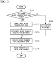
- FIG. 3 is a flowchart showing an example of the blood transfer rate calculation process in the normal control which is performed by the blood transfer rate calculation unit 144.
- the blood transfer rate adjustment data is added to (increased or decreased) the reference set in S113 or S114.
- the roller pump control amount calculation unit 145 calculates a rotational speed (control amount) to be output to the roller pump 120 in each of the normal control and the linked control according to the blood transfer rate sent from the blood transfer rate calculation unit 144.
- the rotational speed of the roller pump 120 is calculated by referring to a data table representing a relationship between the rotational speed and the blood transfer rate of the roller pump 120 which represents a blood transfer rate characteristic of the roller pump 120, or by computing a calculation expression representing the relationship between the rotational speed and the blood transfer rate of the roller pump 120.
- the rotational speed of the roller pump 120 which is set for the linked control is a rotational speed for synchronizing a blood transfer rate of the roller pump 120 with a blood removal rate.
- the roller pump control unit 146 outputs a signal to the roller pump 120 in correspondence with the control amount received from the roller pump control amount calculation unit 145.
- roller pump control unit 146 turns on the linked control display unit 180.
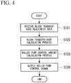
- FIG. 4 is a flowchart showing an example of the operational sequence in the normal control of the artificial heart and lung apparatus 100.
- FIG. 5 is a flowchart showing an example of the operational sequence in the linked control of the artificial heart and lung apparatus 100.
- the process from S131 to S136 is repeatedly executed at predetermined intervals until blood transfer control transitions to the normal control or surgery is complete and the linked control ends.
- FIG. 6 is a flowchart showing an example of the switching of the artificial heart and lung apparatus 100 between the normal control and the linked control.
- the switching of the artificial heart and lung apparatus 100 between the normal control and the linked control is performed in the following sequence.
- the artificial heart and lung apparatus 100 transitions to the linked control (S148). In a case where whether the absolute value of (the blood transfer rate) minus (the calculated blood removal rate) is greater than K (the specific range) (S147: No), the artificial heart and lung apparatus 100 transitions to the normal control (S149).
- the process from S141 to S149 is repeatedly executed at predetermined intervals while the artificial heart and lung apparatus 100 is in operation.
- control unit 140 synchronizes the blood transfer rate of the roller pump 120 with the blood removal rate. As a result, even if the blood removal rate changes, it is possible to stably circulate blood.
- the blood transfer rate adjustment unit 160 includes an encoder with a latch through which an operation amount from an arbitrary position (circumferential position) can be input
- the artificial heart and lung apparatus 100 of the first embodiment has a simple structure. That is, in a case where blood transfer control transitions from the linked control to the normal control, it is not necessary to reset the blood transfer rate adjustment unit 160 by manually returning the blood transfer rate adjustment unit 160 to a specific reference position. As a result, adjustment of the normal control can be efficient due to the elimination of the labor and time required to perform reset.
- the blood transfer rate of the roller pump 120 in the linked control is significantly smaller than a blood transfer rate that is set by the blood transfer rate adjustment unit in the normal control before the blood transfer control transitions to the linked control, it is possible to prevent blood from being transferred at the previous blood transfer rate, which has been set by the blood transfer rate adjustment unit, after transitioning to the normal control, and it is possible to stably circulate blood.
- the blood transfer rate (data relating to a linked blood transfer rate) of the roller pump 120 when blood transfer control transitions from the linked control to the normal control is stored in the linked blood transfer rate storage unit 170, and it is possible to adjust a blood transfer rate in the normal control with respect to the blood transfer rate stored in the linked blood transfer rate storage unit 170. Accordingly, even if a blood removal rate which is set before the blood transfer control transitions to the linked control significantly changes after transitioning to the linked control, it is possible to stably adjust a blood transfer rate after transitioning to the normal control.
- the artificial heart and lung apparatus 100 of the first embodiment includes the roller pump 120 as the blood transfer pump, the artificial heart and lung apparatus 100 is prevented from being affected by pressure, and it is possible to transfer blood at a stable blood transfer rate.
- the blood removal regulator 121 is provided in the blood removal line 101, and thus, it is possible to suitably adjust the flow rate of blood to be removed via the blood removal line 101.
- FIGS. 7 to 11 an artificial heart and lung apparatus (blood circulation system) of a second embodiment of the present invention will be described with reference to FIGS. 7 to 11 .
- FIG. 7 is a circuit diagram showing a schematic configuration of the artificial heart and lung apparatus of the second embodiment.
- Reference sign 200 represents an artificial heart and lung apparatus
- reference sign 112 represents a blood transfer rate sensor (blood transfer rate measurement means)
- reference sign 220 represents a centrifugal pump (blood transfer pump)
- reference sign 240 represents a control unit.
- an artificial heart and lung apparatus 200 includes the blood removal line 101; the reservoir 102; the blood line 103; a centrifugal pump 220; the first blood transfer line (blood transfer line) 104; the artificial lung 105; the second blood transfer line (blood transfer line) 106; the blood removal rate sensor 111; a blood transfer rate sensor 112; the blood removal regulator (flow rate adjustment means) 121; a blood transfer regulator 122; a control unit 240; the blood transfer rate adjustment unit (blood transfer rate instruction means) 160; the linked blood transfer rate storage unit 170; the linked control display unit 180; and the blood transfer control switching unit 190.
- the blood removal line 101, the reservoir 102, the blood line 103, the centrifugal pump 220, the first blood transfer line 104, the artificial lung 105, and the second blood transfer line 106 are connected together in the listed sequence.
- the blood removal regulator 121 and the blood removal rate sensor 111 are disposed in the blood removal line 101 in the listed sequence.
- the blood transfer regulator 122 and the blood transfer rate sensor 112 are disposed in the first blood transfer line 104 in the listed sequence.
- the blood removal line 101, the reservoir 102, the blood line 103, the first blood transfer line 104, the artificial lung 105, the second blood transfer line 106, the blood removal rate sensor 111, the blood removal regulator 121, the blood transfer rate adjustment unit 160, the linked control display unit 180, and the blood transfer control switching unit 190 have the same as those of the first embodiment, and thus, a description thereof will be omitted.
- an ultrasonic sensor is used as the blood transfer rate sensor (blood transfer rate measurement means) 112.
- the blood transfer rate sensor 112 sends a measurement result to the control unit 240.
- the blood transfer rate measurement means includes measurement means for measuring a blood transfer rate, and includes measurement means for measuring various blood removal rate parameters for specifying the blood transfer rate.
- the blood transfer rate parameters are parameters which change in correspondence with a blood transfer rate, and needless to say, include a blood transfer rate. That is, the blood transfer rate parameters include various parameters for specifying the blood transfer rate, for example, the flow speed of transferred blood in a case where a cross-sectional flow path area of the blood transfer line is already known, and a parameter (for example, a change in ultrasonic wave frequency) for specifying the flow speed.
- a comparison between a blood transfer rate parameter and a blood removal rate parameter implies any one of a comparison therebetween in a case where the types of the blood transfer rate parameter and the blood removal rate parameter are the same, a direct comparison therebetween in a case where the types of the blood transfer rate parameter and the blood removal rate parameter are different from each other, and a comparison therebetween after one or both of the blood transfer rate parameter and the blood removal rate parameter are converted into forms in which both can be compared to each other.
- the linked blood transfer rate storage unit 170 is formed of an external memory or the like. In the embodiment, the linked blood transfer rate storage unit 170 stores the blood transfer rate (data relating to a linked blood transfer rate) of the centrifugal pump 220 which is measured by the blood transfer rate sensor 112.
- the centrifugal pump 220 suctions blood stored in the reservoir 102 via the blood line 103, and transfers the blood to the artificial lung 105 via the first blood transfer line 104 by rotating impeller blades via an AC servo motor or a DC servo motor.
- the centrifugal pump 220 is controlled by a control signal output from the control unit 240.
- the rotational speed of the centrifugal pump 220 in normal control is controlled independently from a blood flow rate.
- the rotational speed of the centrifugal pump 220 in linked control is controlled such that a blood transfer rate measured by the blood transfer rate sensor 112 is synchronized with a blood removal rate measured by the blood removal rate sensor 111.
- the rotational speed of the centrifugal pump 220 is feedback controlled in either case.
- the blood transfer regulator 122 is provided in the first blood transfer line 104.
- the blood transfer regulator 122 includes a clamper 122A formed of a pair of clamp members; a servo motor (not shown) that operates the clamper 122A; and a blood transfer regulator operation unit 122B.
- An operator blocks the first blood transfer line 104 by adjusting the amount of clamp (the amount of pinch) of the clamper 122A via the servo motor driven by manually operating the blood transfer regulator operation unit 122B, and thus, the back flowing of blood when the centrifugal pump 220 stops is prevented.
- FIG. 8 is a block diagram showing the schematic configuration of the control unit 240 of the second embodiment.
- the control unit 240 includes the blood transfer rate adjustment data receiving unit 141; the blood removal rate signal input receiving unit 142; the blood removal rate calculation unit 143; a blood transfer rate signal receiving unit 241; a blood transfer rate calculation unit 242; a target blood transfer rate calculation unit 243; a centrifugal pump control amount calculation unit 244; a centrifugal pump control unit 245; and the blood transfer control switching instruction receiving unit 191.
- the control unit 240 is connected to the blood removal rate sensor 111, the blood transfer rate sensor 112, the blood transfer rate adjustment unit 160, the linked blood transfer rate storage unit 170, the linked control display unit 180, the blood transfer control switching unit 190, and the centrifugal pump 220 via cables.
- the blood transfer rate adjustment data receiving unit 141, the blood removal rate signal input receiving unit 142, the blood removal rate calculation unit 143, and the blood transfer control switching instruction receiving unit 191 have the same as those of the first embodiment, and thus, a description thereof will be omitted.
- the blood transfer rate signal receiving unit 241 is connected to the blood transfer rate sensor 112, and receives a blood transfer rate signal (blood transfer rate parameter signal) sent from the blood transfer rate sensor 112.
- the blood transfer rate calculation unit 242 calculates a blood transfer rate according to the blood transfer rate signal sent from the blood transfer rate signal receiving unit 241. Specifically, the blood transfer rate calculation unit 242 is capable of calculating the blood transfer rate by multiplying the blood transfer speed (flow rate parameter), which is calculated from the blood transfer rate signal, by the flow path area of the first blood transfer line 104.
- the target blood transfer rate calculation unit 243 calculates target blood transfer rates of the centrifugal pump 220 in the normal control and the linked control.
- the calculation of a target blood transfer rate performed by the target blood transfer rate calculation unit 243 switches between the normal control and the linked control according to linked control transition conditions and a blood transfer control switching instruction signal received from the blood transfer control switching instruction receiving unit 191.
- a blood transfer rate measured by the blood transfer rate sensor 112 shown in FIG. 3 is used in the switching of the artificial heart and lung apparatus 200 between the normal control and the linked control. Other conditions are the same as those of the first embodiment.
- the target blood transfer rate calculation unit 243 calculates a target blood transfer rate in the normal control according to the blood transfer rate adjustment data received from the blood transfer rate adjustment data receiving unit 141 and the blood transfer rate read from the blood transfer rate storage unit 170.
- the target blood transfer rate calculation unit 243 calculates a target blood transfer rate in the linked control according to the blood transfer rate received from the blood transfer rate calculation unit 242.
- the target blood transfer rate calculation unit 243 stores the blood transfer rate, which has been received from the blood transfer rate calculation unit 242, in the linked blood transfer rate storage unit 170.
- the blood transfer rate of the centrifugal pump 220 which flows through the first blood transfer line 104 and the second blood transfer line 106, is set to coincide with a blood removal rate, and the blood transfer rate is synchronized with the blood removal rate.
- the synchronization of the blood transfer rate of the centrifugal pump 220 with the blood removal rate is one aspect in which the blood transfer rate is controlled to be in a specific range (for example, in a range represented by a ratio to the blood removal rate, or in a range represented by a difference in flow rate with respect to the blood removal rate) with respect to the blood removal rate.
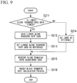
- FIG. 9 is a flowchart showing an example of the target blood transfer rate calculation process in the normal control which is performed by the target blood transfer rate calculation unit 243.
- the blood transfer rate adjustment data is added to (increased or decreased) the reference set in S213 or S214.
- the centrifugal pump control amount calculation unit 244 compares the target blood transfer rate, which has been sent from the target blood transfer rate calculation unit 243, to the blood transfer rate, and calculates a rotational speed (control amount) via feedback control.
- the control amount of the centrifugal pump 220 in the linked control is a control amount that synchronizes the blood transfer rate with the blood removal rate.
- the centrifugal pump control unit 245 outputs a signal to the centrifugal pump 220 in correspondence with the control amount received from the centrifugal pump control amount calculation unit 244.
- the centrifugal pump control unit 245 turns on the linked control display unit 180.
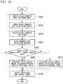
- FIG. 10 is a flowchart showing an example of the operational sequence in the normal control of the artificial heart and lung apparatus 200.
- the process from S221 to S228 is repeatedly executed at predetermined intervals until the artificial heart and lung apparatus 200 transitions to the linked control.
- FIG. 11 is a flowchart showing an example of the operational sequence in the linked control of the artificial heart and lung apparatus 200.
- the process from S231 to S240 is repeatedly executed at predetermined intervals until blood transfer control transitions to the normal control or surgery is complete and the linked control ends.
- control unit 240 synchronizes the blood transfer rate of the centrifugal pump 220 with the blood removal rate. As a result, even if the blood removal rate changes, it is possible to stably circulate blood.
- the blood transfer rate adjustment unit 160 includes an encoder with a latch through which an operation amount from an arbitrary position (circumferential position) can be input
- the artificial heart and lung apparatus 200 of the second embodiment has a simple structure. Accordingly, in a case where blood transfer control transitions from the linked control to the normal control, it is not necessary to reset the blood transfer rate adjustment unit 160 by manually returning the blood transfer rate adjustment unit 160 to a reference position. As a result, adjustment in the normal control can be efficient due to the elimination of the labor and time required to perform reset.
- the blood transfer rate of the centrifugal pump 220 in the linked control is significantly smaller than a blood transfer rate that is set by the blood transfer rate adjustment unit in the normal control before the blood transfer control transitions to the linked control, it is possible to prevent blood from being transferred at the previous blood transfer rate, which has been set by the blood transfer rate adjustment unit, after transitioning to the normal control, and it is possible to stably circulate blood.
- the blood transfer rate (data relating to a linked blood transfer rate) of the centrifugal pump 220 when blood transfer control transitions from the linked control to the normal control is stored in the linked blood transfer rate storage unit 170, and it is possible to adjust a blood transfer rate in the normal control with respect to the blood transfer rate stored in the linked blood transfer rate storage unit 170. Accordingly, even if the blood removal rate which is set before the blood transfer control transitions to the linked control significantly changes after transitioning to the linked control, it is possible to stably adjust the blood transfer rate after transitioning to the normal control.
- the artificial heart and lung apparatus 200 of the second embodiment includes the centrifugal pump 220 as the blood transfer pump, it is possible to promptly transfer blood at a stable blood transfer rate.
- the blood removal regulator 121 is provided in the blood removal line 101, and thus, it is possible to suitably adjust a blood removal rate.
- the blood transfer regulator 122 is provided in the first blood transfer line 104, the blood transfer regulator 122 is capable of preventing the back flowing of blood by blocking the first blood transfer line 104 when the centrifugal pump 220 stops.
- the centrifugal pump 220 is used as a blood transfer pump, and thus, it is possible to promptly transfer blood at a stable blood transfer rate.
- the blood transfer rate is synchronized with the blood removal rate.
- the blood transfer rate may be adjusted to be in a specific range with respect to the blood removal rate.
- the blood transfer rate adjustment unit 160 includes an encoder and a counter.
- a counter may be separated from an encoder, and may be disposed as a portion of each of the control units 140 and 240.
- a device in which an increase and decrease amount is instructed via a (+) press switch and a (-) press switch may be used as an operation amount input unit that outputs pulse signals.
- the artificial heart and lung apparatuses 100 and 200 do not stop when switching between the normal control and the linked control.
- the artificial heart and lung apparatuses 100 and 200 may be configured to stop.
- a blood transfer rate may be adjusted with reference to a linked blood transfer rate stored in the linked blood transfer rate storage unit 170.
- each of the artificial heart and lung apparatuses 100 and 200 includes the linked blood transfer rate storage unit 170.
- setting as to whether the linked blood transfer rate storage unit 170 is included may be arbitrarily performed.
- the linked blood transfer rate storage unit 170 is an external memory connected to each of the control units 140 and 240.
- the configuration and disposition of the linked blood transfer rate storage unit 170 may be arbitrarily set.
- the linked blood transfer rate storage unit 170 stores the blood transfer rate (target blood transfer rate) of the roller pump 120 as data relating to a linked blood transfer rate.
- a blood transfer rate measured by the blood transfer rate sensor 112 is stored.
- data relating to a linked blood transfer rate may be a parameter, for example, a blood removal rate or a control amount of the blood transfer pump, which is capable of definitively setting the blood transfer rate of the blood transfer pump.
- the blood removal rate sensor 111 and the blood transfer rate sensor 112 which measure the flow speed of blood are respectively used as blood removal rate measurement means and blood transfer rate measurement means.
- a blood removal rate and a blood transfer rate may be measured by measuring a blood removal rate parameter (including a blood removal rate) other than a blood removal speed and a blood transfer rate parameter (including a blood transfer rate) other than a blood transfer speed.
- ultrasonic sensors are used as the blood removal rate sensor 111 and the blood transfer rate sensor 112.
- various well-known flow rate measurement means using laser, infrared light, or the like may be used instead of an ultrasonic sensor.
- roller pump 120 and the centrifugal pump 220 are used as blood transfer pumps.
- other types of blood transfer pumps may be used.
- flow rate adjustment means is not provided in the blood transfer lines.
- flow rate sensors such as ultrasonic sensors may be suitably provided in the first blood transfer line 104 and the second blood transfer line 106.
- the blood removal regulator 121 is provided as flow rate adjustment means, and in the second embodiment, the blood removal regulator 121 and the blood transfer regulator 122 are provided as flow rate adjustment means.
- the blood removal regulator 121 and the blood transfer regulator 122 are provided as flow rate adjustment means.
- neither the blood removal regulator 121 nor the blood transfer regulator 122 may be provided.
- flow rate adjustment means setting as to whether either or both of the blood removal regulator 121 and the blood transfer regulator 122 are provided may be suitably performed, and portions of a blood removal line and a blood transfer line, in which the blood removal regulator 121 and the blood transfer regulator 122 are provided, may be suitably set.
- Flow rate measurement means other than the blood removal regulator 121 and the blood transfer regulator 122 may be provided.
- the blood removal regulator 121 and the blood removal rate sensor 111 are disposed in the blood removal line 101 in the listed sequence.
- the blood removal rate sensor 111 and the blood removal regulator 121 are disposed in the listed sequence.
- the blood transfer regulator 122 and the blood transfer rate sensor 112 are disposed in the first blood transfer line 104 in the listed sequence.
- the blood transfer regulator 122 and the blood transfer rate sensor 112 may be disposed in the second blood transfer line 106 instead of the first blood transfer line 104.
- the blood transfer rate sensor 112 and the blood transfer regulator 122 may be disposed in the listed sequence.
- control may be performed via methods (algorithms) other than the methods shown in the flowcharts.
- each of the artificial heart and lung apparatuses 100 and 200 includes the reservoir 102.
- an auxiliary circulation apparatus blood circulation system
- an auxiliary circulation apparatus without the reservoir 102 may be used to prevent the occurrence of excessive negative pressure by synchronizing the blood transfer rate with the blood removal rate or adjusting the blood transfer rate to be in a specific range with respect to the blood removal rate.
- the blood transfer rate of the blood transfer pump is linked with the blood removal rate, it is possible to stably transfer blood, and to efficiently circulate blood.
Landscapes
- Health & Medical Sciences (AREA)
- Heart & Thoracic Surgery (AREA)
- Engineering & Computer Science (AREA)
- Cardiology (AREA)
- Hematology (AREA)
- Anesthesiology (AREA)
- Biomedical Technology (AREA)
- Life Sciences & Earth Sciences (AREA)
- Animal Behavior & Ethology (AREA)
- General Health & Medical Sciences (AREA)
- Public Health (AREA)
- Veterinary Medicine (AREA)
- Vascular Medicine (AREA)
- Mechanical Engineering (AREA)
- Urology & Nephrology (AREA)
- Emergency Medicine (AREA)
- Pulmonology (AREA)
- Medical Informatics (AREA)
- External Artificial Organs (AREA)
Claims (3)
- Blutumwälzsystem (100), das an den Körper eines Menschen angeschlossen werden kann und das entnommenes Blut über eine Bluttransferpumpe in den Körper des Menschen überführt, wobei das System umfasst: die Bluttransferpumpe (120);
eine Blutentnahmeleitung (101), durch die entnommenes Blut zur Bluttransferpumpe fließt;
eine Bluttransferleitung (104, 106), die Blut, das von der Bluttransferpumpe gefördert wird, in den Körper des Menschen (P) überführt;
eine Blutentnahmeraten-Messeinrichtung (111), die in der Blutentnahmeleitung bereitgestellt ist;
eine Steuereinheit (140), die dafür ausgelegt ist, eine verknüpfte Steuerung der Bluttransferpumpe entsprechend einer Blutentnahmerate, die von der Blutentnahmeraten-Messeinrichtung gemessen wird, durchzuführen, so dass eine Bluttransferrate der Bluttransferpumpe in Bezug auf die Blutentnahmerate in einem bestimmten Bereich liegt; und
eine Bluttransferraten-Anweisungseinrichtung (160, 170) zum Anweisen einer Soll-Bluttransferrate der Bluttransferpumpe bei einer normalen Steuerung, bei der die Bluttransferpumpe Blut unabhängig von der Blutentnahmerate überträgt,
wobei die Bluttransferraten-Anweisungseinrichtung eine Bluttransferraten-Anpassungseinheit (160) aufweist, und
wobei die Bluttransferraten-Anpassungseinheit (160) aufweist:eine Betätigungsumfangseingabeeinheit, welche die Bluttransferrate über eine manuelle Betätigung anpassen kann und ein Impulssignal gemäß dem eingegebenen Betätigungsumfang der manuellen Betätigung ausgibt; undeinen Zähler, der einen Erhöhungs- und Senkungsbetrag der Transferrate als Bluttransferrate auf Basis von Impulssignalen ausgibt, die von der Betätigungsumfangseingabeeinheit ausgegeben werden, und der Zähler den Erhöhungs- und Senkungsbetrag der Transferrate als Bluttransferrate in Bezug auf den Ausgabewert der Betätigungsumfangseingabeeinheit ausgibt, wenn die Bluttransfersteuerung auf die normale Steuerung übergeht. - Blutumwälzsystem (100) nach Anspruch 1.
wobei die Bluttransferraten-Anweisungseinrichtung (160, 170) eine Speichereinheit (170) für eine verknüpfte Bluttransferrate aufweist, die Daten in Bezug auf eine verknüpfte Bluttransferrate speichert, die eine Bluttransferrate für die verknüpfte Steuerung ist, wenn die Bluttransfersteuerung von der verknüpften Steuerung auf die normale Steuerung übergeht, und
wobei in einem Fall, wo die Bluttransfersteuerung von der verknüpften Steuerung auf die normale Steuerung übergeht, die Steuereinheit (140) die Bluttransferrate gemäß den Daten steuert, die auf eine verknüpfte Bluttransferrate bezogen sind, die in der Speichereinheit für die verknüpften Bluttransferraten gespeichert sind. - Blutumwälzsystem (100) nach Anspruch 1 oder 2
wobei die Bluttransferraten-Anpassungseinheit (160) einen Encoder aufweist, der den Betätigungsumfang gemäß einem Drehwinkel eines zu ihm gehörenden Latch, durch den ein Betätigungsumfang von einer beliebigen Position aus eingegeben werden kann, erhöht oder senkt.
Applications Claiming Priority (4)
| Application Number | Priority Date | Filing Date | Title |
|---|---|---|---|
| JP2014167559 | 2014-08-20 | ||
| JP2015053600A JP5839212B1 (ja) | 2014-08-20 | 2015-03-17 | 血液循環システム |
| JP2015114037A JP6484113B2 (ja) | 2014-08-20 | 2015-06-04 | 血液循環システム |
| PCT/JP2015/073425 WO2016027866A1 (ja) | 2014-08-20 | 2015-08-20 | 血液循環システム |
Publications (3)
| Publication Number | Publication Date |
|---|---|
| EP3165246A1 EP3165246A1 (de) | 2017-05-10 |
| EP3165246A4 EP3165246A4 (de) | 2017-07-26 |
| EP3165246B1 true EP3165246B1 (de) | 2018-09-26 |
Family
ID=55069255
Family Applications (3)
| Application Number | Title | Priority Date | Filing Date |
|---|---|---|---|
| EP15833783.2A Active EP3167920B1 (de) | 2014-08-20 | 2015-08-20 | Blutzirkulationssystem |
| EP15833016.7A Active EP3184130B1 (de) | 2014-08-20 | 2015-08-20 | Blutzirkulationssystem |
| EP15832993.8A Active EP3165246B1 (de) | 2014-08-20 | 2015-08-20 | Blutzirkulationssystem |
Family Applications Before (2)
| Application Number | Title | Priority Date | Filing Date |
|---|---|---|---|
| EP15833783.2A Active EP3167920B1 (de) | 2014-08-20 | 2015-08-20 | Blutzirkulationssystem |
| EP15833016.7A Active EP3184130B1 (de) | 2014-08-20 | 2015-08-20 | Blutzirkulationssystem |
Country Status (6)
| Country | Link |
|---|---|
| US (5) | US10786617B2 (de) |
| EP (3) | EP3167920B1 (de) |
| JP (6) | JP5839212B1 (de) |
| CN (3) | CN106794298B (de) |
| BR (1) | BR112017002576B1 (de) |
| WO (1) | WO2016027868A1 (de) |
Families Citing this family (20)
| Publication number | Priority date | Publication date | Assignee | Title |
|---|---|---|---|---|
| JP5985996B2 (ja) * | 2013-01-18 | 2016-09-06 | 泉工医科工業株式会社 | エアリーク検出装置及びそれを備えた電動式吸引器 |
| JP5839212B1 (ja) * | 2014-08-20 | 2016-01-06 | 泉工医科工業株式会社 | 血液循環システム |
| GB2538577B (en) * | 2015-05-21 | 2017-08-23 | Spectrum Medical Ltd | Control system |
| GB2547900B (en) * | 2016-03-01 | 2018-03-28 | Spectrum Medical Ltd | Flow control system |
| ES2754405T3 (es) * | 2016-08-23 | 2020-04-17 | Abiomed Europe Gmbh | Dispositivo de asistencia ventricular |
| JP6890817B2 (ja) * | 2016-12-15 | 2021-06-18 | 泉工医科工業株式会社 | 血液循環システム |
| JP2018094243A (ja) * | 2016-12-15 | 2018-06-21 | 泉工医科工業株式会社 | 血液循環システム |
| JP2019058250A (ja) * | 2017-09-25 | 2019-04-18 | 泉工医科工業株式会社 | ローラポンプ |
| CN110151295A (zh) * | 2017-11-15 | 2019-08-23 | 林斌 | 一种腔静脉旁路血液灌流冷冻消融系统 |
| JP2020074912A (ja) * | 2018-11-07 | 2020-05-21 | 泉工医科工業株式会社 | 遠心ポンプ制御装置、遠心ポンプ及び遠心ポンプ制御方法 |
| JP2020118553A (ja) * | 2019-01-24 | 2020-08-06 | 株式会社鷺宮製作所 | 超音波流量計、流体循環装置および流量測定方法 |
| EP4534120A3 (de) | 2019-06-27 | 2025-07-09 | LivaNova Deutschland GmbH | Vorrichtung zur automatischen bestimmung des venösen zuflusses zu einem blutreservoir eines extrakorporalen blutkreislaufs |
| CN110538353A (zh) * | 2019-08-19 | 2019-12-06 | 江苏赛腾医疗科技有限公司 | 体外心肺支持辅助系统 |
| US11406748B2 (en) * | 2020-02-24 | 2022-08-09 | CardiacAssist, Inc | Dual lumen cannula with expandable lumen |
| CN111529785B (zh) * | 2020-05-20 | 2021-06-11 | 浙江大学 | 一种可调节血液流量的透析机 |
| CN111772730A (zh) * | 2020-06-22 | 2020-10-16 | 合肥市第二人民医院 | 一种溶栓导液装置 |
| CN112807503A (zh) * | 2020-07-28 | 2021-05-18 | 高艳云 | 应用数值分析的透析模式调节系统 |
| US12246122B2 (en) * | 2021-05-07 | 2025-03-11 | Terumo Cardiovascular Systems Corporation | Heart-lung machine with semi-autonomous initiation mode |
| CN115400280A (zh) * | 2022-09-01 | 2022-11-29 | 吉林大学中日联谊医院 | 一种ecmo用双房血流调节器 |
| WO2024135522A1 (ja) * | 2022-12-23 | 2024-06-27 | 国立大学法人広島大学 | 血液循環システムの制御装置、制御方法及びプログラム |
Family Cites Families (42)
| Publication number | Priority date | Publication date | Assignee | Title |
|---|---|---|---|---|
| US4370983A (en) | 1971-01-20 | 1983-02-01 | Lichtenstein Eric Stefan | Computer-control medical care system |
| JPS60142859A (ja) | 1983-12-29 | 1985-07-29 | 泉工医科工業株式会社 | 拍動血流量自動設定機構付ロ−ラポンプ |
| JPS6227966A (ja) | 1985-07-30 | 1987-02-05 | 泉工医科工業株式会社 | 人工心肺装置における脱血レギユレ−タ |
| US4650457A (en) * | 1985-08-16 | 1987-03-17 | Kuraray Co., Ltd. | Apparatus for extracorporeal lung assist |
| JPS63143078A (ja) * | 1986-12-03 | 1988-06-15 | 株式会社クラレ | 呼吸補助装置 |
| DE3720667A1 (de) | 1987-06-23 | 1989-01-05 | Schael Wilfried | Haemodialyse- und haemofiltrationsvorrichtung |
| JPS6449565A (en) * | 1987-08-18 | 1989-02-27 | Shiroshi Nishiuchi | Apparatus for automatically controlling extracorporeal blood circulation |
| US5178603A (en) | 1990-07-24 | 1993-01-12 | Baxter International, Inc. | Blood extraction and reinfusion flow control system and method |
| EP0659444B1 (de) | 1993-12-20 | 1999-05-26 | Stöckert Instrumente GmbH | Vorrichtung zum Pumpen von Blut |
| WO1999015212A1 (en) | 1997-09-24 | 1999-04-01 | The Cleveland Clinic Foundation | Flow controlled blood pump system |
| DE19622184A1 (de) | 1996-06-03 | 1997-12-04 | Joern Martens | Tragbares Gerät zur Langzeit-Perfusion von menschlichen und tierischen Geweben, als Herz-Lungen-Nieren-Leber-Maschine, für die umfassende, funktionell stützende Behandlung und besonders auch für die lebenserhaltende Notfall-Perfusion, zur Notfall-Versorgung von Patienten |
| US5813972A (en) | 1996-09-30 | 1998-09-29 | Minnesota Mining And Manufacturing Company | Medical perfusion system with data communications network |
| US6024692A (en) * | 1997-07-03 | 2000-02-15 | Dilling; Emery W. | Fluid circulator for nonlinear compliant circuits |
| JP4051812B2 (ja) * | 1998-04-13 | 2008-02-27 | 株式会社ジェイ・エム・エス | 制御機能を備えた体外循環装置 |
| JP4063988B2 (ja) * | 1999-01-20 | 2008-03-19 | 泉工医科工業株式会社 | 体外循環血液回路 |
| JP2000245829A (ja) * | 1999-03-04 | 2000-09-12 | Senko Medical Instr Mfg Co Ltd | 人工心肺装置 |
| CN100363066C (zh) | 2000-10-12 | 2008-01-23 | 肾脏治疗公司 | 在体液体外处理中用于体液流动控制的装置和方法 |
| JP2006020712A (ja) * | 2004-07-06 | 2006-01-26 | Senko Medical Instr Mfg Co Ltd | 人工心肺装置 |
| JP4282567B2 (ja) * | 2004-08-03 | 2009-06-24 | 嶌田 泰之 | 送血管およびこれを用いた血液供給装置 |
| JP2006325750A (ja) * | 2005-05-24 | 2006-12-07 | Senko Medical Instr Mfg Co Ltd | 血液循環システム及びその制御装置 |
| US7981280B2 (en) | 2006-01-06 | 2011-07-19 | Renal Solutions, Inc. | Recirculation of blood in an extracorporeal blood treatment system |
| DE102007007198A1 (de) * | 2007-02-09 | 2008-08-14 | Maquet Cardiopulmonary Ag | Verfahren und Vorrichtung zur Überwachung und Optimierung eines durch eine Pumpe bewirkten Blutkreislaufs |
| US8267370B2 (en) | 2008-10-28 | 2012-09-18 | Medical Components, Inc. | Clamp for flexible tubing |
| JP5243227B2 (ja) * | 2008-12-22 | 2013-07-24 | 東芝機械株式会社 | 転写装置、転写システムおよび転写方法 |
| US8562507B2 (en) * | 2009-02-27 | 2013-10-22 | Thoratec Corporation | Prevention of aortic valve fusion |
| IN2012DN01832A (de) | 2009-08-12 | 2015-06-05 | Miami Children S Hospital Res Inst | |
| DE102009060668A1 (de) | 2009-12-28 | 2011-06-30 | Fresenius Medical Care Deutschland GmbH, 61352 | Vorrichtung und Verfahren zur Überwachung einer extrakorporalen Blutbehandlung |
| JP5321480B2 (ja) * | 2010-01-25 | 2013-10-23 | 株式会社ジェイ・エム・エス | 体外循環装置 |
| WO2012141756A2 (en) * | 2011-04-09 | 2012-10-18 | Merlini Patricia | Voice control of automated heart-lung machine |
| US9061099B2 (en) | 2011-04-29 | 2015-06-23 | Medtronic, Inc. | Cardiovascular monitoring for fluid removal processes |
| US9532898B2 (en) | 2011-07-15 | 2017-01-03 | Cardiacassist, Inc. | Apparatus and method for rapidly cooling or heating the body temperature of a patient |
| AU2012296568A1 (en) * | 2011-08-17 | 2014-03-06 | Flow Forward Medical, Inc. | Blood pump systems and methods |
| US9789241B2 (en) * | 2012-03-01 | 2017-10-17 | Medical Device Works Nv | System for monitoring and controlling organ blood perfusion |
| JP5962894B2 (ja) | 2012-03-09 | 2016-08-03 | 国立大学法人広島大学 | 送血流量制御装置および体外循環装置 |
| JP5952141B2 (ja) * | 2012-08-31 | 2016-07-13 | 京セラメディカル株式会社 | 人工心肺ポンプ用駆動装置 |
| US8888730B2 (en) * | 2012-09-19 | 2014-11-18 | Sorin Group Italia S.R.L. | Perfusion system with RFID feature activation |
| JP5469728B1 (ja) * | 2012-10-19 | 2014-04-16 | 日機装株式会社 | 液体流路の圧力検出装置 |
| US9623164B2 (en) | 2013-02-01 | 2017-04-18 | Medtronic, Inc. | Systems and methods for multifunctional volumetric fluid control |
| US9173987B2 (en) * | 2013-02-01 | 2015-11-03 | Medtronic, Inc. | Degassing module for a controlled compliant flow path |
| JP6310467B2 (ja) * | 2013-09-20 | 2018-04-11 | テルモ株式会社 | 表示装置及び表示方法 |
| JP5839212B1 (ja) * | 2014-08-20 | 2016-01-06 | 泉工医科工業株式会社 | 血液循環システム |
| GB2538577B (en) | 2015-05-21 | 2017-08-23 | Spectrum Medical Ltd | Control system |
-
2015
- 2015-03-17 JP JP2015053600A patent/JP5839212B1/ja active Active
- 2015-06-04 JP JP2015114037A patent/JP6484113B2/ja active Active
- 2015-06-05 JP JP2015114878A patent/JP6484114B2/ja active Active
- 2015-06-22 JP JP2015124810A patent/JP6745589B2/ja active Active
- 2015-07-23 JP JP2015146146A patent/JP6517616B2/ja active Active
- 2015-08-07 JP JP2015157773A patent/JP2016043262A/ja active Pending
- 2015-08-20 CN CN201580044082.2A patent/CN106794298B/zh active Active
- 2015-08-20 WO PCT/JP2015/073428 patent/WO2016027868A1/ja not_active Ceased
- 2015-08-20 US US15/503,501 patent/US10786617B2/en active Active
- 2015-08-20 EP EP15833783.2A patent/EP3167920B1/de active Active
- 2015-08-20 CN CN201580044054.0A patent/CN106659841B/zh active Active
- 2015-08-20 BR BR112017002576-0A patent/BR112017002576B1/pt not_active IP Right Cessation
- 2015-08-20 US US15/502,091 patent/US10751463B2/en active Active
- 2015-08-20 EP EP15833016.7A patent/EP3184130B1/de active Active
- 2015-08-20 CN CN201580042928.9A patent/CN106659840A/zh active Pending
- 2015-08-20 EP EP15832993.8A patent/EP3165246B1/de active Active
- 2015-08-20 US US15/502,949 patent/US11040132B2/en active Active
-
2018
- 2018-06-12 US US16/006,277 patent/US11141519B2/en active Active
-
2021
- 2021-10-11 US US17/498,422 patent/US12268804B2/en active Active
Also Published As
Similar Documents
| Publication | Publication Date | Title |
|---|---|---|
| EP3165246A1 (de) | Blutzirkulationssystem | |
| US8298427B2 (en) | Apparatus for extracorporeal blood treatment and method for managing such an apparatus | |
| WO1993009822A1 (en) | Hemodialysis conductivity servo-proportioning system | |
| JP2006325750A (ja) | 血液循環システム及びその制御装置 | |
| US20130062283A1 (en) | Device for regulating at least one filtration value, haemodialysis machine and corresponding method and use | |
| US11992594B2 (en) | Blood circulation system | |
| WO2016027866A1 (ja) | 血液循環システム | |
| CN110860009A (zh) | 一种新生儿换血控制方法 | |
| EP3656413B1 (de) | Vorrichtung zur erkennung der blockierung einer substitutionsleitung eines hämodialysesystems | |
| CN211536001U (zh) | 新生儿换血控制平台 | |
| WO2016027852A1 (ja) | 血液循環システム | |
| WO2014049643A1 (ja) | 生命維持装置のためのコントローラ及びその制御方法 | |
| JP7219444B2 (ja) | 送血ポンプ制御装置、送血ポンプ | |
| JP2018094243A (ja) | 血液循環システム |
Legal Events
| Date | Code | Title | Description |
|---|---|---|---|
| STAA | Information on the status of an ep patent application or granted ep patent |
Free format text: STATUS: THE INTERNATIONAL PUBLICATION HAS BEEN MADE |
|
| PUAI | Public reference made under article 153(3) epc to a published international application that has entered the european phase |
Free format text: ORIGINAL CODE: 0009012 |
|
| STAA | Information on the status of an ep patent application or granted ep patent |
Free format text: STATUS: REQUEST FOR EXAMINATION WAS MADE |
|
| 17P | Request for examination filed |
Effective date: 20170201 |
|
| AK | Designated contracting states |
Kind code of ref document: A1 Designated state(s): AL AT BE BG CH CY CZ DE DK EE ES FI FR GB GR HR HU IE IS IT LI LT LU LV MC MK MT NL NO PL PT RO RS SE SI SK SM TR |
|
| AX | Request for extension of the european patent |
Extension state: BA ME |
|
| A4 | Supplementary search report drawn up and despatched |
Effective date: 20170623 |
|
| RIC1 | Information provided on ipc code assigned before grant |
Ipc: A61M 1/14 20060101ALI20170616BHEP Ipc: A61M 1/36 20060101AFI20170616BHEP Ipc: A61M 1/10 20060101ALI20170616BHEP |
|
| DAV | Request for validation of the european patent (deleted) | ||
| DAX | Request for extension of the european patent (deleted) | ||
| GRAP | Despatch of communication of intention to grant a patent |
Free format text: ORIGINAL CODE: EPIDOSNIGR1 |
|
| STAA | Information on the status of an ep patent application or granted ep patent |
Free format text: STATUS: GRANT OF PATENT IS INTENDED |
|
| INTG | Intention to grant announced |
Effective date: 20180508 |
|
| GRAS | Grant fee paid |
Free format text: ORIGINAL CODE: EPIDOSNIGR3 |
|
| GRAA | (expected) grant |
Free format text: ORIGINAL CODE: 0009210 |
|
| STAA | Information on the status of an ep patent application or granted ep patent |
Free format text: STATUS: THE PATENT HAS BEEN GRANTED |
|
| AK | Designated contracting states |
Kind code of ref document: B1 Designated state(s): AL AT BE BG CH CY CZ DE DK EE ES FI FR GB GR HR HU IE IS IT LI LT LU LV MC MK MT NL NO PL PT RO RS SE SI SK SM TR |
|
| REG | Reference to a national code |
Ref country code: GB Ref legal event code: FG4D |
|
| REG | Reference to a national code |
Ref country code: CH Ref legal event code: EP |
|
| REG | Reference to a national code |
Ref country code: AT Ref legal event code: REF Ref document number: 1045250 Country of ref document: AT Kind code of ref document: T Effective date: 20181015 |
|
| REG | Reference to a national code |
Ref country code: IE Ref legal event code: FG4D |
|
| REG | Reference to a national code |
Ref country code: DE Ref legal event code: R096 Ref document number: 602015017295 Country of ref document: DE |
|
| REG | Reference to a national code |
Ref country code: NL Ref legal event code: MP Effective date: 20180926 |
|
| PG25 | Lapsed in a contracting state [announced via postgrant information from national office to epo] |
Ref country code: RS Free format text: LAPSE BECAUSE OF FAILURE TO SUBMIT A TRANSLATION OF THE DESCRIPTION OR TO PAY THE FEE WITHIN THE PRESCRIBED TIME-LIMIT Effective date: 20180926 Ref country code: BG Free format text: LAPSE BECAUSE OF FAILURE TO SUBMIT A TRANSLATION OF THE DESCRIPTION OR TO PAY THE FEE WITHIN THE PRESCRIBED TIME-LIMIT Effective date: 20181226 Ref country code: GR Free format text: LAPSE BECAUSE OF FAILURE TO SUBMIT A TRANSLATION OF THE DESCRIPTION OR TO PAY THE FEE WITHIN THE PRESCRIBED TIME-LIMIT Effective date: 20181227 Ref country code: LT Free format text: LAPSE BECAUSE OF FAILURE TO SUBMIT A TRANSLATION OF THE DESCRIPTION OR TO PAY THE FEE WITHIN THE PRESCRIBED TIME-LIMIT Effective date: 20180926 Ref country code: NO Free format text: LAPSE BECAUSE OF FAILURE TO SUBMIT A TRANSLATION OF THE DESCRIPTION OR TO PAY THE FEE WITHIN THE PRESCRIBED TIME-LIMIT Effective date: 20181226 Ref country code: FI Free format text: LAPSE BECAUSE OF FAILURE TO SUBMIT A TRANSLATION OF THE DESCRIPTION OR TO PAY THE FEE WITHIN THE PRESCRIBED TIME-LIMIT Effective date: 20180926 Ref country code: SE Free format text: LAPSE BECAUSE OF FAILURE TO SUBMIT A TRANSLATION OF THE DESCRIPTION OR TO PAY THE FEE WITHIN THE PRESCRIBED TIME-LIMIT Effective date: 20180926 |
|
| REG | Reference to a national code |
Ref country code: LT Ref legal event code: MG4D |
|
| PG25 | Lapsed in a contracting state [announced via postgrant information from national office to epo] |
Ref country code: HR Free format text: LAPSE BECAUSE OF FAILURE TO SUBMIT A TRANSLATION OF THE DESCRIPTION OR TO PAY THE FEE WITHIN THE PRESCRIBED TIME-LIMIT Effective date: 20180926 Ref country code: LV Free format text: LAPSE BECAUSE OF FAILURE TO SUBMIT A TRANSLATION OF THE DESCRIPTION OR TO PAY THE FEE WITHIN THE PRESCRIBED TIME-LIMIT Effective date: 20180926 Ref country code: AL Free format text: LAPSE BECAUSE OF FAILURE TO SUBMIT A TRANSLATION OF THE DESCRIPTION OR TO PAY THE FEE WITHIN THE PRESCRIBED TIME-LIMIT Effective date: 20180926 |
|
| REG | Reference to a national code |
Ref country code: AT Ref legal event code: MK05 Ref document number: 1045250 Country of ref document: AT Kind code of ref document: T Effective date: 20180926 |
|
| PG25 | Lapsed in a contracting state [announced via postgrant information from national office to epo] |
Ref country code: RO Free format text: LAPSE BECAUSE OF FAILURE TO SUBMIT A TRANSLATION OF THE DESCRIPTION OR TO PAY THE FEE WITHIN THE PRESCRIBED TIME-LIMIT Effective date: 20180926 Ref country code: CZ Free format text: LAPSE BECAUSE OF FAILURE TO SUBMIT A TRANSLATION OF THE DESCRIPTION OR TO PAY THE FEE WITHIN THE PRESCRIBED TIME-LIMIT Effective date: 20180926 Ref country code: PL Free format text: LAPSE BECAUSE OF FAILURE TO SUBMIT A TRANSLATION OF THE DESCRIPTION OR TO PAY THE FEE WITHIN THE PRESCRIBED TIME-LIMIT Effective date: 20180926 Ref country code: NL Free format text: LAPSE BECAUSE OF FAILURE TO SUBMIT A TRANSLATION OF THE DESCRIPTION OR TO PAY THE FEE WITHIN THE PRESCRIBED TIME-LIMIT Effective date: 20180926 Ref country code: AT Free format text: LAPSE BECAUSE OF FAILURE TO SUBMIT A TRANSLATION OF THE DESCRIPTION OR TO PAY THE FEE WITHIN THE PRESCRIBED TIME-LIMIT Effective date: 20180926 Ref country code: IS Free format text: LAPSE BECAUSE OF FAILURE TO SUBMIT A TRANSLATION OF THE DESCRIPTION OR TO PAY THE FEE WITHIN THE PRESCRIBED TIME-LIMIT Effective date: 20190126 Ref country code: ES Free format text: LAPSE BECAUSE OF FAILURE TO SUBMIT A TRANSLATION OF THE DESCRIPTION OR TO PAY THE FEE WITHIN THE PRESCRIBED TIME-LIMIT Effective date: 20180926 Ref country code: EE Free format text: LAPSE BECAUSE OF FAILURE TO SUBMIT A TRANSLATION OF THE DESCRIPTION OR TO PAY THE FEE WITHIN THE PRESCRIBED TIME-LIMIT Effective date: 20180926 |
|
| PG25 | Lapsed in a contracting state [announced via postgrant information from national office to epo] |
Ref country code: PT Free format text: LAPSE BECAUSE OF FAILURE TO SUBMIT A TRANSLATION OF THE DESCRIPTION OR TO PAY THE FEE WITHIN THE PRESCRIBED TIME-LIMIT Effective date: 20190126 Ref country code: SM Free format text: LAPSE BECAUSE OF FAILURE TO SUBMIT A TRANSLATION OF THE DESCRIPTION OR TO PAY THE FEE WITHIN THE PRESCRIBED TIME-LIMIT Effective date: 20180926 Ref country code: SK Free format text: LAPSE BECAUSE OF FAILURE TO SUBMIT A TRANSLATION OF THE DESCRIPTION OR TO PAY THE FEE WITHIN THE PRESCRIBED TIME-LIMIT Effective date: 20180926 |
|
| REG | Reference to a national code |
Ref country code: DE Ref legal event code: R097 Ref document number: 602015017295 Country of ref document: DE |
|
| PG25 | Lapsed in a contracting state [announced via postgrant information from national office to epo] |
Ref country code: DK Free format text: LAPSE BECAUSE OF FAILURE TO SUBMIT A TRANSLATION OF THE DESCRIPTION OR TO PAY THE FEE WITHIN THE PRESCRIBED TIME-LIMIT Effective date: 20180926 |
|
| PLBE | No opposition filed within time limit |
Free format text: ORIGINAL CODE: 0009261 |
|
| STAA | Information on the status of an ep patent application or granted ep patent |
Free format text: STATUS: NO OPPOSITION FILED WITHIN TIME LIMIT |
|
| 26N | No opposition filed |
Effective date: 20190627 |
|
| PG25 | Lapsed in a contracting state [announced via postgrant information from national office to epo] |
Ref country code: SI Free format text: LAPSE BECAUSE OF FAILURE TO SUBMIT A TRANSLATION OF THE DESCRIPTION OR TO PAY THE FEE WITHIN THE PRESCRIBED TIME-LIMIT Effective date: 20180926 |
|
| PG25 | Lapsed in a contracting state [announced via postgrant information from national office to epo] |
Ref country code: TR Free format text: LAPSE BECAUSE OF FAILURE TO SUBMIT A TRANSLATION OF THE DESCRIPTION OR TO PAY THE FEE WITHIN THE PRESCRIBED TIME-LIMIT Effective date: 20180926 |
|
| PG25 | Lapsed in a contracting state [announced via postgrant information from national office to epo] |
Ref country code: CH Free format text: LAPSE BECAUSE OF NON-PAYMENT OF DUE FEES Effective date: 20190831 Ref country code: MC Free format text: LAPSE BECAUSE OF FAILURE TO SUBMIT A TRANSLATION OF THE DESCRIPTION OR TO PAY THE FEE WITHIN THE PRESCRIBED TIME-LIMIT Effective date: 20180926 Ref country code: LU Free format text: LAPSE BECAUSE OF NON-PAYMENT OF DUE FEES Effective date: 20190820 Ref country code: LI Free format text: LAPSE BECAUSE OF NON-PAYMENT OF DUE FEES Effective date: 20190831 |
|
| REG | Reference to a national code |
Ref country code: BE Ref legal event code: MM Effective date: 20190831 |
|
| PG25 | Lapsed in a contracting state [announced via postgrant information from national office to epo] |
Ref country code: IE Free format text: LAPSE BECAUSE OF NON-PAYMENT OF DUE FEES Effective date: 20190820 |
|
| PG25 | Lapsed in a contracting state [announced via postgrant information from national office to epo] |
Ref country code: BE Free format text: LAPSE BECAUSE OF NON-PAYMENT OF DUE FEES Effective date: 20190831 |
|
| PG25 | Lapsed in a contracting state [announced via postgrant information from national office to epo] |
Ref country code: CY Free format text: LAPSE BECAUSE OF FAILURE TO SUBMIT A TRANSLATION OF THE DESCRIPTION OR TO PAY THE FEE WITHIN THE PRESCRIBED TIME-LIMIT Effective date: 20180926 |
|
| PG25 | Lapsed in a contracting state [announced via postgrant information from national office to epo] |
Ref country code: HU Free format text: LAPSE BECAUSE OF FAILURE TO SUBMIT A TRANSLATION OF THE DESCRIPTION OR TO PAY THE FEE WITHIN THE PRESCRIBED TIME-LIMIT; INVALID AB INITIO Effective date: 20150820 Ref country code: MT Free format text: LAPSE BECAUSE OF FAILURE TO SUBMIT A TRANSLATION OF THE DESCRIPTION OR TO PAY THE FEE WITHIN THE PRESCRIBED TIME-LIMIT Effective date: 20180926 |
|
| PG25 | Lapsed in a contracting state [announced via postgrant information from national office to epo] |
Ref country code: MK Free format text: LAPSE BECAUSE OF FAILURE TO SUBMIT A TRANSLATION OF THE DESCRIPTION OR TO PAY THE FEE WITHIN THE PRESCRIBED TIME-LIMIT Effective date: 20180926 |
|
| P01 | Opt-out of the competence of the unified patent court (upc) registered |
Effective date: 20230519 |
|
| PGFP | Annual fee paid to national office [announced via postgrant information from national office to epo] |
Ref country code: GB Payment date: 20250626 Year of fee payment: 11 |
|
| PGFP | Annual fee paid to national office [announced via postgrant information from national office to epo] |
Ref country code: FR Payment date: 20250610 Year of fee payment: 11 |
|
| PGFP | Annual fee paid to national office [announced via postgrant information from national office to epo] |
Ref country code: DE Payment date: 20250624 Year of fee payment: 11 |
|
| PGFP | Annual fee paid to national office [announced via postgrant information from national office to epo] |
Ref country code: IT Payment date: 20250722 Year of fee payment: 11 |