EP3165252B1 - Verbindungsstück, behälter mit solchem verbindungsstück und flüssigkeitaufbereitungsvorrichtung mit passendem verbindungsstück für einen solchen behälter - Google Patents
Verbindungsstück, behälter mit solchem verbindungsstück und flüssigkeitaufbereitungsvorrichtung mit passendem verbindungsstück für einen solchen behälter Download PDFInfo
- Publication number
- EP3165252B1 EP3165252B1 EP16187113.2A EP16187113A EP3165252B1 EP 3165252 B1 EP3165252 B1 EP 3165252B1 EP 16187113 A EP16187113 A EP 16187113A EP 3165252 B1 EP3165252 B1 EP 3165252B1
- Authority
- EP
- European Patent Office
- Prior art keywords
- connector
- fluid
- container
- fluid line
- mounting means
- Prior art date
- Legal status (The legal status is an assumption and is not a legal conclusion. Google has not performed a legal analysis and makes no representation as to the accuracy of the status listed.)
- Expired - Lifetime
Links
Images




Classifications
-
- A—HUMAN NECESSITIES
- A61—MEDICAL OR VETERINARY SCIENCE; HYGIENE
- A61M—DEVICES FOR INTRODUCING MEDIA INTO, OR ONTO, THE BODY; DEVICES FOR TRANSDUCING BODY MEDIA OR FOR TAKING MEDIA FROM THE BODY; DEVICES FOR PRODUCING OR ENDING SLEEP OR STUPOR
- A61M1/00—Suction or pumping devices for medical purposes; Devices for carrying-off, for treatment of, or for carrying-over, body-liquids; Drainage systems
- A61M1/14—Dialysis systems; Artificial kidneys; Blood oxygenators ; Reciprocating systems for treatment of body fluids, e.g. single needle systems for hemofiltration or pheresis
- A61M1/16—Dialysis systems; Artificial kidneys; Blood oxygenators ; Reciprocating systems for treatment of body fluids, e.g. single needle systems for hemofiltration or pheresis with membranes
- A61M1/1654—Dialysates therefor
- A61M1/1656—Apparatus for preparing dialysates
-
- A—HUMAN NECESSITIES
- A61—MEDICAL OR VETERINARY SCIENCE; HYGIENE
- A61M—DEVICES FOR INTRODUCING MEDIA INTO, OR ONTO, THE BODY; DEVICES FOR TRANSDUCING BODY MEDIA OR FOR TAKING MEDIA FROM THE BODY; DEVICES FOR PRODUCING OR ENDING SLEEP OR STUPOR
- A61M1/00—Suction or pumping devices for medical purposes; Devices for carrying-off, for treatment of, or for carrying-over, body-liquids; Drainage systems
- A61M1/14—Dialysis systems; Artificial kidneys; Blood oxygenators ; Reciprocating systems for treatment of body fluids, e.g. single needle systems for hemofiltration or pheresis
- A61M1/16—Dialysis systems; Artificial kidneys; Blood oxygenators ; Reciprocating systems for treatment of body fluids, e.g. single needle systems for hemofiltration or pheresis with membranes
- A61M1/1654—Dialysates therefor
- A61M1/1656—Apparatus for preparing dialysates
- A61M1/1666—Apparatus for preparing dialysates by dissolving solids
-
- A—HUMAN NECESSITIES
- A61—MEDICAL OR VETERINARY SCIENCE; HYGIENE
- A61M—DEVICES FOR INTRODUCING MEDIA INTO, OR ONTO, THE BODY; DEVICES FOR TRANSDUCING BODY MEDIA OR FOR TAKING MEDIA FROM THE BODY; DEVICES FOR PRODUCING OR ENDING SLEEP OR STUPOR
- A61M1/00—Suction or pumping devices for medical purposes; Devices for carrying-off, for treatment of, or for carrying-over, body-liquids; Drainage systems
- A61M1/14—Dialysis systems; Artificial kidneys; Blood oxygenators ; Reciprocating systems for treatment of body fluids, e.g. single needle systems for hemofiltration or pheresis
- A61M1/16—Dialysis systems; Artificial kidneys; Blood oxygenators ; Reciprocating systems for treatment of body fluids, e.g. single needle systems for hemofiltration or pheresis with membranes
- A61M1/1654—Dialysates therefor
- A61M1/1656—Apparatus for preparing dialysates
- A61M1/1668—Details of containers
-
- A—HUMAN NECESSITIES
- A61—MEDICAL OR VETERINARY SCIENCE; HYGIENE
- A61M—DEVICES FOR INTRODUCING MEDIA INTO, OR ONTO, THE BODY; DEVICES FOR TRANSDUCING BODY MEDIA OR FOR TAKING MEDIA FROM THE BODY; DEVICES FOR PRODUCING OR ENDING SLEEP OR STUPOR
- A61M39/00—Tubes, tube connectors, tube couplings, valves, access sites or the like, specially adapted for medical use
- A61M39/10—Tube connectors or tube couplings
- A61M39/105—Multi-channel connectors or couplings, e.g. for connecting multi-lumen tubes
-
- F—MECHANICAL ENGINEERING; LIGHTING; HEATING; WEAPONS; BLASTING
- F16—ENGINEERING ELEMENTS AND UNITS; GENERAL MEASURES FOR PRODUCING AND MAINTAINING EFFECTIVE FUNCTIONING OF MACHINES OR INSTALLATIONS; THERMAL INSULATION IN GENERAL
- F16L—PIPES; JOINTS OR FITTINGS FOR PIPES; SUPPORTS FOR PIPES, CABLES OR PROTECTIVE TUBING; MEANS FOR THERMAL INSULATION IN GENERAL
- F16L3/00—Supports for pipes, cables or protective tubing, e.g. hangers, holders, clamps, cleats, clips, brackets
- F16L3/22—Supports for pipes, cables or protective tubing, e.g. hangers, holders, clamps, cleats, clips, brackets specially adapted for supporting a number of parallel pipes at intervals
-
- A—HUMAN NECESSITIES
- A61—MEDICAL OR VETERINARY SCIENCE; HYGIENE
- A61J—CONTAINERS SPECIALLY ADAPTED FOR MEDICAL OR PHARMACEUTICAL PURPOSES; DEVICES OR METHODS SPECIALLY ADAPTED FOR BRINGING PHARMACEUTICAL PRODUCTS INTO PARTICULAR PHYSICAL OR ADMINISTERING FORMS; DEVICES FOR ADMINISTERING FOOD OR MEDICINES ORALLY; BABY COMFORTERS; DEVICES FOR RECEIVING SPITTLE
- A61J1/00—Containers specially adapted for medical or pharmaceutical purposes
- A61J1/05—Containers specially adapted for medical or pharmaceutical purposes for collecting, storing or administering blood, plasma or medical fluids ; Infusion or perfusion containers
- A61J1/10—Bag-type containers
-
- A—HUMAN NECESSITIES
- A61—MEDICAL OR VETERINARY SCIENCE; HYGIENE
- A61J—CONTAINERS SPECIALLY ADAPTED FOR MEDICAL OR PHARMACEUTICAL PURPOSES; DEVICES OR METHODS SPECIALLY ADAPTED FOR BRINGING PHARMACEUTICAL PRODUCTS INTO PARTICULAR PHYSICAL OR ADMINISTERING FORMS; DEVICES FOR ADMINISTERING FOOD OR MEDICINES ORALLY; BABY COMFORTERS; DEVICES FOR RECEIVING SPITTLE
- A61J1/00—Containers specially adapted for medical or pharmaceutical purposes
- A61J1/14—Details; Accessories therefor
- A61J1/1475—Inlet or outlet ports
-
- A—HUMAN NECESSITIES
- A61—MEDICAL OR VETERINARY SCIENCE; HYGIENE
- A61J—CONTAINERS SPECIALLY ADAPTED FOR MEDICAL OR PHARMACEUTICAL PURPOSES; DEVICES OR METHODS SPECIALLY ADAPTED FOR BRINGING PHARMACEUTICAL PRODUCTS INTO PARTICULAR PHYSICAL OR ADMINISTERING FORMS; DEVICES FOR ADMINISTERING FOOD OR MEDICINES ORALLY; BABY COMFORTERS; DEVICES FOR RECEIVING SPITTLE
- A61J1/00—Containers specially adapted for medical or pharmaceutical purposes
- A61J1/14—Details; Accessories therefor
- A61J1/16—Holders for containers
-
- A—HUMAN NECESSITIES
- A61—MEDICAL OR VETERINARY SCIENCE; HYGIENE
- A61M—DEVICES FOR INTRODUCING MEDIA INTO, OR ONTO, THE BODY; DEVICES FOR TRANSDUCING BODY MEDIA OR FOR TAKING MEDIA FROM THE BODY; DEVICES FOR PRODUCING OR ENDING SLEEP OR STUPOR
- A61M39/00—Tubes, tube connectors, tube couplings, valves, access sites or the like, specially adapted for medical use
- A61M39/10—Tube connectors or tube couplings
- A61M2039/1083—Tube connectors or tube couplings having a plurality of female connectors, e.g. Luer connectors
-
- Y—GENERAL TAGGING OF NEW TECHNOLOGICAL DEVELOPMENTS; GENERAL TAGGING OF CROSS-SECTIONAL TECHNOLOGIES SPANNING OVER SEVERAL SECTIONS OF THE IPC; TECHNICAL SUBJECTS COVERED BY FORMER USPC CROSS-REFERENCE ART COLLECTIONS [XRACs] AND DIGESTS
- Y10—TECHNICAL SUBJECTS COVERED BY FORMER USPC
- Y10S—TECHNICAL SUBJECTS COVERED BY FORMER USPC CROSS-REFERENCE ART COLLECTIONS [XRACs] AND DIGESTS
- Y10S604/00—Surgery
- Y10S604/905—Aseptic connectors or couplings, e.g. frangible, piercable
-
- Y—GENERAL TAGGING OF NEW TECHNOLOGICAL DEVELOPMENTS; GENERAL TAGGING OF CROSS-SECTIONAL TECHNOLOGIES SPANNING OVER SEVERAL SECTIONS OF THE IPC; TECHNICAL SUBJECTS COVERED BY FORMER USPC CROSS-REFERENCE ART COLLECTIONS [XRACs] AND DIGESTS
- Y10—TECHNICAL SUBJECTS COVERED BY FORMER USPC
- Y10T—TECHNICAL SUBJECTS COVERED BY FORMER US CLASSIFICATION
- Y10T137/00—Fluid handling
- Y10T137/6851—With casing, support, protector or static constructional installations
-
- Y—GENERAL TAGGING OF NEW TECHNOLOGICAL DEVELOPMENTS; GENERAL TAGGING OF CROSS-SECTIONAL TECHNOLOGIES SPANNING OVER SEVERAL SECTIONS OF THE IPC; TECHNICAL SUBJECTS COVERED BY FORMER USPC CROSS-REFERENCE ART COLLECTIONS [XRACs] AND DIGESTS
- Y10—TECHNICAL SUBJECTS COVERED BY FORMER USPC
- Y10T—TECHNICAL SUBJECTS COVERED BY FORMER US CLASSIFICATION
- Y10T137/00—Fluid handling
- Y10T137/9029—With coupling
Definitions
- the invention relates to the field of connectors for connecting a container with a fluid preparation device for preparing a fluid.
- the invention also relates to such containers and fluid preparation devices, in particular to dialysis devices.
- the plug component has a coaxial design for the two flow paths.
- the complementary plug component on the dialysis device therefore has a rather sophisticated design which in turn requires elaborate solutions to make routine rinsing and disinfection of this part of the dialysis device possible.
- the plug component on the bag has a circular design the manufacturing process of such a bag affords special processes as the plug component is usually welded into a complementary hole in a side wall of the bag. More simple techniques assessing the bag only from the top are hence not applicable.
- the concept of the invention is based on the observation that by separating the mounting means which comprises both fluid line connector parts for the two fluid lines to be connected to two fluid lines of the fluid preparation device, into two laterally spaced-apart mounting means, each incorporating the orifices of one of the two connector parts, it is possible to set up a connector system which significantly simplifies the handling and manufacturing processes. With the aid of the inventive concept it is in particular possible to design a container to be connected to a fluid preparation device, which is mounted in a suspended fashion with the connector parts being used at the same time in a hook-like fashion at the uppermost point of the container to realize an optimum stability of the mounted container.
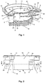
- FIG 1 an embodiment of a connector according to the invention is shown in a perspective view.
- the connector 1 has two bar-like, laterally spaced-apart mounting means 2 and 4.
- Such mounting means may easily be mounted to a mating mounting means by insertion in an axial direction.
- the interior of the mounting means 2 an 4 is hollow thus defining first and second orifices 3 and 5.
- the connector 1 has a boat-like cross-section with a wide middle part 6 and two wing-like projections 7 and 8 on opposing sides of the middle part 6.
- the boat-like cross-section simplifies the joining of the connector to a containment portion of a container like a flexible tube bag considerably, as is known in the art of manufacturing flexible bags.
- a rip structure 19 at the lower end 16 of the connector 1.
- the middle part 6 of the boat-like cross-section shows a fifth orifice 11 which extends from the upper end 17 to the lower end 16.
- the orifice 11 may be used for prefilling the containment portion to be joined to the connector during the manufacturing process with a substance.
- the mounting means 2 and 4 protrude from the wing-like projections 7 and 8 by protrusions 28 and 29 in a direction which is perpendicular to the axes of the mounting means 2 and 4 and thus also to the axes of the orifices 3, 5 and 11, which are all parallel.
- the protrusions 28 and 29 are tangential to one side of the wing-like projections 7 and 8.
- first end 13 of a handle 12 is joined to the first mounting means 2 and a second end 14 of the handle 12 is joined to the second mounting means 4.
- ends 13 and 14 may comprise flexible film joints.
- the connector 1 also comprises a ledge 15 which joins the second mounting means 4 with the middle part 6 of the connector 1.
- This ledge 15 serves as a counterpart for a detector means at the mating connectors site for confirming the correct mount of the connector.
- FIG 2 a sectional view of the connector 1 is shown where the middle part 6 and the wing-like projections 7 and 8 are cut along their middle, and the view is from the back as seen in figure 1 .
- the connector 1 extends from the lower end 16 to the upper end 17.
- the continuous orifice 11 for enabling an easy prefilling of the containment portion to be joined to the lower end 16 of the connector is seen.
- first wing-like projection 7 there is also a continuous third orifice 9 and in the second wing-like projection 8 a continuous fourth orifice 10.
- third and fourth orifice 9 and 10 have a varying cross-section along their extensions from the lower end 16 to the upper 17 of the container 1, this has no influence on the fact that a fluid communication is established along these extensions.
- the third orifice 9 extents to a first distribution chamber 20 and the fourth orifice 10 to a second distribution chamber 21.
- the distribution chambers 20 and 21 are in fluid communication with the first and second orifices 3 and 5 by slots 22 and 23, respectively.
- the connector 1 By mounting the connector 1 in a mating mounting means to be described below, fluid communication is thus established from the first orifice 3 to the third orifice 9 which hence constitutes a first fluid line, and from the second orifice 5 to the fourth orifice 10 which constitutes a second fluid line.
- Figure 3 shows a further sectional view along the line A-A as indicated in figure 2 .
- the protrusions 28 and 29 of the two mounting means 2 and 4 and thus the first and second orifices 3 and 5 in a direction perpendicular to the vertical extension of the wing-like projections 7 and 8 and the middle part 6 of the connector 1 are displayed more clearly.
- the connector 1 shown in figures 1 to 3 is representing the connector portion, the lower end 16 to be joined to a containment portion of the container.
- the upper end 17 is sealed along the circumference 26 - which is also encircling and thus sealing the fifth orifice 11 - by a flexible sheet 18 by welding or similiar known joining techniques. It it worth noting that due to the design of the connector the flow paths for the first and second fluid lines are not blocked by this seal.
- the flexible sheet 18 is indicated in figure 2 .
- the containment portion 31 of the container 30 is made from a tube bag which is sealed at the lower end 32 and joined by welding or similar techniques in a leak-proof manner at the upper end 33 to the lower end 16 of the connector 1.
- the container 30 is furthermore prefilled with a powdered concentrate 34 of a substance to be dissolved for final usage.
- the substance may be provided in any other condition, solid or fluid, whatever may be useful for the particular purpose.
- the lower ends 24 and 25 of the orifices 3 and 5 may be sealed in an appropriate way so that the interior of the container 30 is completely sealed to the exterior.
- a single flap-like seal 27 is shown in figure 8 which is sealing both orifices 3 and 5.
- the seal 27 may be removed by a user before usage by peeling off the seal as shown in figure 8 .
- tubes and/or filters may be provided in the container 30 which are placed in the first and/or second fluid line in order to filter passing fluid flowing in and/or out the bag and/or extend the lines to a particular site within the containment portion 31. If it is desired to withdraw a saturated solution of a substance to be dissolved it may prove useful to introduce the flushing and hence dissolving fluid like water close to the upper end 33 of the containment portion 31 and to withdraw the saturated solution close to the lower end 32 of the containment portion 30.
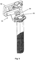
- FIG 4 there is also shown a part 50 of an embodiment for a fluid preparation device according to the invention which has mating first and second mounting means 53 and 54 for mounting the connector 1 and thus container 30.
- These mating first and second mounting means are formed by first and second insertion chambers 53 and 54 which have a complementary cross-section such that the first and second bar-like mounting means 2 and 4 can be mounted by insertion into these chambers.
- Any cross-section may be used, but a circular cross-section as shown in this embodiment is advantageous in view of improved rinsing and disinfection properties.
- the first insertion chamber 53 is in fluid communication with a third fluid line 51, the flushing fluid line, which is connected to a flushing fluid source (not shown) for the delivery of flushing fluid.
- This flushing fluid is required during use of the container 30 in order to prepare the prepared fluid from the prefilled substance and the flushing fluid - the latter being in most cases simply water.
- the second insertion chamber 54 is in fluid communication with a fourth fluid line 52, the prepared fluid line, which enables the delivery of the prepared fluid to a place where it is required. This may still be within the fluid preparation device or by means of a suitable outlet for the delivery to somewhere else.
- the part 50 of the fluid preparation device also comprises a detector means 58 which in this embodiment is a mechanical microswitch.
- a detector means 58 which in this embodiment is a mechanical microswitch.
- the switch 58 which by a not shown electronic evaluation circuit of the fluid preparation device enables the device to confirm the correct mount of the connector 1. It may be possible that this evaluation circuit causes any actuators to block the flow of any flushing fluid into the first insertion chamber 53 until such confirmation has taken place.
- the part 50 of the fluid preparation device further comprises a lid 59.
- the lid 59 is turnable around a joint 65 from a first, open position which is shown in figure 4 , to a third, closed and preferable locked position which will be described below. Between the first and the third position, the lid is arrestable, preferably lockable, in a second position with the container 30 being mounted as will also be explained below.
- the lid 59 has first and second closure parts 60 and 61 which are suitable to close the first and second insertion chambers 53 and 54, respectively, when the lid 59 is in the third position.
- Figure 5 shows the same view as figure 4 with the connector 1 and thus the container 30 being mounted to the part 50 of the fluid preparation device.
- the first and second mounting means 2 and 4 are inserted in the first and second insertion chambers 53 and 54.
- there are two proximity detectors 63 and 64 on the part 50 which detect the presence of the lid 59 in either the second or the third position.
- These proximity sensors may be non-mechanical sensors like Hall sensors which notice the close position of certain parts of the lid 59.
- These sensors may as well comprise mechanical switching means which are actuated by movable counterparts (not shown) of the lid which at the time serve to lock the lid 59 in the second or third position.
- Figure 6 shows a first sectional view of the arrangement shown in figure 5 with the lid 59 being in the second position, arresting the connector 1 in its mounted position by pushing with the closure parts 60 and 61 onto the connector 1.
- the sectional view is taken along the flushing fluid line 51 and the first insertion chamber 53 looking from left to right in figure 5 .
- the prepared fluid line 52 and the second insertion chamber 54 have a symmetric design.
- first male connector element 55 which terminates the flushing fluid line 51 within the first insertion chamber 53.
- the first male connector element 55 is joined to the housing of part 50 with a flexible sealing and compensation element 57 which may be made of any suitable material, e.g. rubber.
- the sealing and compensation element 57 enables movements of the first male connector element 55 relative to the housing in order to compensate tolerances which may exist for the relevant counterparts of the connector 1.
- first orifice 3 and hence the first fluid line of the connector 1 and container 30 are now in fluid communication with the flushing fluid line 51.
- the orifice 3 is limited by first sealing lips 66 at the lower circumference of the first mounting means 2.
- the sealing lips 66 may easily be created by injection molding.
- the lips 66 assure a leak-proofed connection to the first male connector element 55 which they encompass at its outer circumference.
- the first mounting means 2 is inserted into the first insertion chamber 53 as far until a first step-like projection 69 of the first mounting means 2 is touching the housing of the part 50 of the fluid preparation device.
- a second male connector element for connection of the second and fourth fluid lines there are corresponding elements, i.e. a second male connector element, a second sealing and compensation element, second sealing lips, a second step-like projection and a branching sixth fluid line.
- FIG. 7 shows a second sectional view of the part 50 of the fluid preparation device. It differs from figure 6 by the fact that no connector 1 is mounted and that the lid 59 is in the closed, third position.
- the first insertion chamber 53 is now closed by the first closure part 60 which is a part of the lid 59.
- the closure is sealed by sealing means 67 on the outer circumference of the first closure part 60, which here is accomplished by an o-ring gasket.
- the fluid lines of the part 50 of the fluid preparation device may easily be rinsed with any fluid like water or disinfection fluid.
- the rinsing fluid may be provided by the third fluid line, i.e. the flushing fluid line 51.
- the flushing fluid then enters the first insertion chamber 53 and leaves it via the fifth line 62.
- the fifth and sixth lines are joined (not shown).
- the rinsing fluid hence enters the second insertion chamber 54 by the sixth fluid line and leaves it by the fourth fluid line, i.e. the prepared fluid line 52.
- the connector 1 or container 30, respectively, may be designed as a disposable article for single-use purposes. Hence special solutions for their disinfection have not to be found. In this case a sensitive part like the sealing lips 66 is automatically exhanged from one use to another without affording any extra parts or expensive maintenance procedures.
- the detector means 63 and 64 sense the lid 59 in the second or the third position.
- the electronic evaluation circuitry of the fluid preparation device is monitoring the signals provided by these detector means in order to confirm an expected position of the lid 59 during specific modes of the fluid preparation device like disinfection or online fluid preparation.
- the boat-like cross section of the connector 1 represents a preferred embodiment. Any other shape of the connector which still meets the concept of the invention as outlined by the claims would nevertheless enable an easy handling of the connector system during use. As is apparent from figures 4 to 7 the shape of this part of the connector hardly has any influence on the connection steps themselves.
- the invention is hence providing easy to handle and reliable components for a fluid preparation system consisting of a container with a special connector and a fluid preparation device.
- the container may be prefilled with a substance, but also applications are possible where an initially empty container is used which will be filled and/or emptied during use.
- the container can be of any type, rigid or flexible.
- a flexible bag represents however a preferred embodiment.
- the components of the inventive system are particularly useful in the medical field where the handling is especially sensitive to sterility conditions. At the same time the invention provides inexpensive solutions which is not of lesser interest.
- the invention has proven particularly useful in the field of dialysis where the fluid preparation device is part of the dialysis device.
- the prepared fluid may represent only a part of the complete dialysis fluid like bicarbonate, or the complete dialysis fluid. It may be applied to any type of dialysis like hemodialysis or peritoneal dialysis.
Landscapes
- Health & Medical Sciences (AREA)
- Heart & Thoracic Surgery (AREA)
- Urology & Nephrology (AREA)
- Engineering & Computer Science (AREA)
- Hematology (AREA)
- Anesthesiology (AREA)
- Life Sciences & Earth Sciences (AREA)
- Animal Behavior & Ethology (AREA)
- General Health & Medical Sciences (AREA)
- Public Health (AREA)
- Veterinary Medicine (AREA)
- Biomedical Technology (AREA)
- Vascular Medicine (AREA)
- Emergency Medicine (AREA)
- General Engineering & Computer Science (AREA)
- Pulmonology (AREA)
- Mechanical Engineering (AREA)
- External Artificial Organs (AREA)
- Infusion, Injection, And Reservoir Apparatuses (AREA)
- Medical Preparation Storing Or Oral Administration Devices (AREA)
- Bag Frames (AREA)
- Coating Apparatus (AREA)
- Details Of Connecting Devices For Male And Female Coupling (AREA)
- Connector Housings Or Holding Contact Members (AREA)
- Containers And Packaging Bodies Having A Special Means To Remove Contents (AREA)
Claims (23)
- Behälter (30) mit
einem Aufnahmeabschnitt (31) und
einem Verbindungsabschnitt (1),
wobei der Verbindungsabschnitt einen Verbinder (1) zum Verbinden von Fluidleitungen
mit
einem ersten Verbinderteil (2), der eine erste Öffnung (3) zum Verbinden einer ersten Fluidleitung mit einer dritten Fluidleitung bereitstellt,
einem zweiten Verbinderteil (4) zum Bereitstellen einer zweiten Öffnung (5) zum Verbinden einer zweiten Fluidleitung mit einer vierten Fluidleitung,
einem Anbringungsmittel (2, 4), das die Verbindung des ersten (2) und des zweiten (4) Verbinderteils mit Pass-Teilen eines Gegen-Verbinders ermöglicht, umfasst,
wobei das Anbringungsmittel zwei seitlich beabstandete Anbringungsmittel (2, 4) umfasst, die eine Verbindung mit zwei in gleicher Weise seitlich beabstandeten Gegen-Anbringungsmitteln des Gegen-Verbinders ermöglichen, wobei jedes der beiden Anbringungsmittel (2, 4) eine der beiden Öffnungen (3, 5) enthält,
dadurch gekennzeichnet, dass
der Verbinder (1) zwei flügelförmige Vorsprünge (7, 8) auf gegenüberliegenden Seiten eines Mittelabschnitts (6) aufweist, und wobei jedes der beiden Anbringungsmittel (2, 4) von einem der beiden flügelförmigen Vorsprünge (7, 8) vorragt,
dass die beiden Anbringungsmittel (2, 4) in einer Richtung vorragen, die senkrecht zu den Achsen der Anbringungsmittel (2, 4) verläuft,
die beiden Öffnungen (3, 5) der Anbringungsmittel durch Dichtlippen (66) begrenzt sind, die sich an dem unteren Umfang der Anbringungsmittel (2, 4) befinden. - Behälter nach Anspruch 1, dadurch gekennzeichnet, dass der Verbinder (1) einen bootförmigen Querschnitt mit einem breiten Mittelabschnitt (6) aufweist.
- Behälter nach Anspruch 1 oder 2, dadurch gekennzeichnet, dass eine dritte Öffnung (9) in dem ersten flügelförmigen Vorsprung (7) und eine vierte Öffnung (10) in dem zweiten flügelförmigen Vorsprung (8) vorgesehen ist.
- Behälter nach Anspruch 3, dadurch gekennzeichnet, dass eine fünfte Öffnung (11) in dem Mittelabschnitt (6) vorgesehen ist.
- Behälter nach einem der vorhergehenden Ansprüche, dadurch gekennzeichnet, dass der Verbinder (1) ferner ein Griffmittel (12) mit zwei Enden (13, 14) umfasst, die jeweils mit einem der Anbringungsmittel (2, 4) zusammengefügt sind.
- Behälter nach einem der Ansprüche 2 bis 5, dadurch gekennzeichnet, dass der Verbinder (1) ferner eine Verstärkungsrippe (15) umfasst, die den Mittelabschnitt (6) und ein Anbringungsmittel (4) zusammenfügt.
- Behälter nach einem der Ansprüche 1 bis 6, dadurch gekennzeichnet, dass der Aufnahmeabschnitt einen Beutel (31) umfasst.
- Behälter nach Anspruch 7, dadurch gekennzeichnet, dass der Beutel (31) von der Art eines Schlauchbeutels ist, wobei ein Ende (32) davon abgedichtet ist und das andere Ende (33) durch den Verbinder (1) abgeschlossen ist.
- Behälter nach einem der Ansprüche 5 bis 8, dadurch gekennzeichnet, dass der Behälter mit einem trockenen oder einem fluiden Medium (34) gefüllt ist.
- Behälter nach Anspruch 9, dadurch gekennzeichnet, dass das trockene oder fluide Medium (34) ein Bestandteil, insbesondere ein Konzentrat, eines Dialysefluids ist.
- Behälter nach einem der Ansprüche 1 bis 10, dadurch gekennzeichnet, dass ein unteres Ende (16) des Verbinders (1) durch den Aufnahmeabschnitt (31) gegenüber der Atmosphäre abgedichtet ist, dass ein oberes Ende (17) des Verbinders (1) durch eine Dichtung (18) gegenüber der Atmosphäre abgedichtet ist und dass die erste (3) und die zweite (5) Öffnung durch eine weitere Dichtung (27) gegenüber der Atmosphäre abgedichtet sind.
- Kombination aus einem Behälter und einer Fluidaufbereitungsvorrichtung (50)
mit einer Quelle für ein Spülfluid, die mit einer Spülfluidleitung (51) verbunden ist,
mit einer Leitung (52) für das aufbereitete Fluid für das aufzubereitende Fluid,
mit einem Anbringungsverbinderteil (53, 54), der zum Anbringen und Verbinden eines Behälters derart, dass die Spülfluidleitung (51) und die Leitung (52) für das aufbereitete Fluid in Fluidverbindung mit dem Inneren des Behälters (30) stehen, geeignet ist,
dadurch gekennzeichnet, dass
der Behälter der Behälter (30) nach einem der Ansprüche 1 bis 11 ist, und
dass der Anbringungsverbinderteil das erste (53) und das zweite (54) Gegen-Anbringungsmittel umfasst,
dass die Spülfluidleitung (51) die dritte Fluidleitung ist und
dass die Leitung (52) für das aufbereitete Fluid die vierte Fluidleitung ist. - Kombination nach Anspruch 12, dadurch gekennzeichnet, dass das erste (53) und das zweite (54) Gegen-Anbringungsmittel eine erste (53) und eine zweite (54) Einschubkammer sind, in die das erste (2) und das zweite (4) Anbringungsmittel des Verbinders (1) zum Verbinden einschiebbar sind und die ein erstes Steckverbinderelement (55), das die Spülfluidleitung (51) abschließt, und ein zweites Steckverbinderelement, das die Leitung (52) für das aufbereitete Fluid abschließt, umfassen.
- Kombination nach Anspruch 13, dadurch gekennzeichnet, dass ein Dichtungs- und Ausgleichselement (57) sowohl in der ersten (53) als auch der zweiten (54) Einschubkammer eingeschoben ist, um das erste (55) und das zweite Steckverbinderelement abzudichten und deren Bewegungen auszugleichen.
- Kombination nach einem der Ansprüche 12 bis 14, dadurch gekennzeichnet, dass die erste (53) und die zweite (54) Einschubkammer eine parallele Ausrichtung aufweisen.
- Kombination nach einem der Ansprüche 12 bis 15, dadurch gekennzeichnet, dass die Fluidaufbereitungsvorrichtung (50) ferner ein Detektormittel (58) zum Detektieren des Vorhandenseins des Verbinders (1) umfasst.
- Kombination nach einem der Ansprüche 12 bis 16, dadurch gekennzeichnet, dass die Fluidaufbereitungsvorrichtung (50) ferner einen Deckel (59) zum Abdecken des Anbringungsverbinderteils umfasst.
- Kombination nach den Ansprüchen 13 und 17, dadurch gekennzeichnet, dass der Deckel (59) einen ersten Verschlussteil (60) zum Verschließen der ersten Einschubkammer (53) und einen zweiten Verschlussteil (61) zum Verschließen der zweiten Einschubkammer (54) umfasst.
- Kombinationsvorrichtung nach Anspruch 18, dadurch gekennzeichnet, dass die Fluidaufbereitungsvorrichung (50) ferner eine fünfte Fluidleitung (62), die in Fluidverbindung mit der ersten Einschubkammer (53) und folglich der Spülfluidleitung (51) steht, wenn der erste Verschlussteil (60) die erste Einschubkammer (53) verschließt, und eine sechste Fluidleitung, die in Fluidverbindung mit der Leitung (52) für das aufbereitete Fluid steht, wenn der zweite Verschlussteil (61) die zweite Einschubkammer (54) verschließt, umfasst.
- Kombination nach Anspruch 19, dadurch gekennzeichnet, dass die fünfte (62) und die sechste Fluidleitung zusammengefügt sind.
- Kombination nach einem der Ansprüche 17 bis 20, dadurch gekennzeichnet, dass der Deckel (59) zwischen einer ersten Position, die das Anbringen und/oder Abnehmen des Verbinders (1) ermöglicht, einer zweiten Position, in der der angebrachte Verbinder (1) durch den Deckel (59) an seinem Platz gehalten wird, und einer dritten Position, in der die erste (53) und die zweite (54) Einschubkammer verschlossen sind und kein Verbinder (1) angebracht ist, bewegbar ist.
- Kombination nach Anspruch 21, dadurch gekennzeichnet, dass sie ferner ein Deckelpositionsdetektormittel (63, 64) zum Detektieren einer, einiger oder aller drei Positionen des Deckels umfasst.
- Kombination nach einem der Ansprüche 12 bis 22, dadurch gekennzeichnet, dass die Fluidaufbereitungsvorrichtung (50) ein Teil einer Dialysefluidaufbereitungsvorrichtung ist und dass das aufbereitete Fluid das Dialysefluid oder ein Teil desselben ist.
Priority Applications (1)
| Application Number | Priority Date | Filing Date | Title |
|---|---|---|---|
| EP16187113.2A EP3165252B1 (de) | 2002-03-11 | 2002-03-11 | Verbindungsstück, behälter mit solchem verbindungsstück und flüssigkeitaufbereitungsvorrichtung mit passendem verbindungsstück für einen solchen behälter |
Applications Claiming Priority (5)
| Application Number | Priority Date | Filing Date | Title |
|---|---|---|---|
| EP02005510A EP1344550B1 (de) | 2002-03-11 | 2002-03-11 | Verbindungsstück, Behälter mit solchem Verbindungsstück und Flüssigkeitaufbereitungsvorrichtung mit passendem Verbindungsstück für einen solchen Behälter |
| EP10009237.8A EP2308548B1 (de) | 2002-03-11 | 2002-03-11 | Verbindungsstück, Behälter mit solchem Verbindungsstück und Flüssigkeitaufbereitungsvorrichtung mit passendem Verbindungsstück für einen solchen Behälter |
| EP20090014818 EP2161052B1 (de) | 2002-03-11 | 2002-03-11 | Verbindungsstück, Behälter mit solchem Verbindungsstück und Flüssigkeitaufbereitungsvorrichtung mit passendem Verbindungsstück für einen solchen Behälter |
| EP16187113.2A EP3165252B1 (de) | 2002-03-11 | 2002-03-11 | Verbindungsstück, behälter mit solchem verbindungsstück und flüssigkeitaufbereitungsvorrichtung mit passendem verbindungsstück für einen solchen behälter |
| EP20050024894 EP1642614B1 (de) | 2002-03-11 | 2002-03-11 | Behälter mit Verbindungsstück und Dialyseflüssigkeitaufbereitungsvorrichtung dafür |
Related Parent Applications (5)
| Application Number | Title | Priority Date | Filing Date |
|---|---|---|---|
| EP20090014818 Division EP2161052B1 (de) | 2002-03-11 | 2002-03-11 | Verbindungsstück, Behälter mit solchem Verbindungsstück und Flüssigkeitaufbereitungsvorrichtung mit passendem Verbindungsstück für einen solchen Behälter |
| EP10009237.8A Division EP2308548B1 (de) | 2002-03-11 | 2002-03-11 | Verbindungsstück, Behälter mit solchem Verbindungsstück und Flüssigkeitaufbereitungsvorrichtung mit passendem Verbindungsstück für einen solchen Behälter |
| EP10009237.8A Previously-Filed-Application EP2308548B1 (de) | 2002-03-11 | 2002-03-11 | Verbindungsstück, Behälter mit solchem Verbindungsstück und Flüssigkeitaufbereitungsvorrichtung mit passendem Verbindungsstück für einen solchen Behälter |
| EP20050024894 Division EP1642614B1 (de) | 2002-03-11 | 2002-03-11 | Behälter mit Verbindungsstück und Dialyseflüssigkeitaufbereitungsvorrichtung dafür |
| EP02005510A Division EP1344550B1 (de) | 2002-03-11 | 2002-03-11 | Verbindungsstück, Behälter mit solchem Verbindungsstück und Flüssigkeitaufbereitungsvorrichtung mit passendem Verbindungsstück für einen solchen Behälter |
Publications (2)
| Publication Number | Publication Date |
|---|---|
| EP3165252A1 EP3165252A1 (de) | 2017-05-10 |
| EP3165252B1 true EP3165252B1 (de) | 2021-04-07 |
Family
ID=27763352
Family Applications (5)
| Application Number | Title | Priority Date | Filing Date |
|---|---|---|---|
| EP16187113.2A Expired - Lifetime EP3165252B1 (de) | 2002-03-11 | 2002-03-11 | Verbindungsstück, behälter mit solchem verbindungsstück und flüssigkeitaufbereitungsvorrichtung mit passendem verbindungsstück für einen solchen behälter |
| EP02005510A Expired - Lifetime EP1344550B1 (de) | 2002-03-11 | 2002-03-11 | Verbindungsstück, Behälter mit solchem Verbindungsstück und Flüssigkeitaufbereitungsvorrichtung mit passendem Verbindungsstück für einen solchen Behälter |
| EP10009237.8A Expired - Lifetime EP2308548B1 (de) | 2002-03-11 | 2002-03-11 | Verbindungsstück, Behälter mit solchem Verbindungsstück und Flüssigkeitaufbereitungsvorrichtung mit passendem Verbindungsstück für einen solchen Behälter |
| EP20090014818 Expired - Lifetime EP2161052B1 (de) | 2002-03-11 | 2002-03-11 | Verbindungsstück, Behälter mit solchem Verbindungsstück und Flüssigkeitaufbereitungsvorrichtung mit passendem Verbindungsstück für einen solchen Behälter |
| EP20050024894 Expired - Lifetime EP1642614B1 (de) | 2002-03-11 | 2002-03-11 | Behälter mit Verbindungsstück und Dialyseflüssigkeitaufbereitungsvorrichtung dafür |
Family Applications After (4)
| Application Number | Title | Priority Date | Filing Date |
|---|---|---|---|
| EP02005510A Expired - Lifetime EP1344550B1 (de) | 2002-03-11 | 2002-03-11 | Verbindungsstück, Behälter mit solchem Verbindungsstück und Flüssigkeitaufbereitungsvorrichtung mit passendem Verbindungsstück für einen solchen Behälter |
| EP10009237.8A Expired - Lifetime EP2308548B1 (de) | 2002-03-11 | 2002-03-11 | Verbindungsstück, Behälter mit solchem Verbindungsstück und Flüssigkeitaufbereitungsvorrichtung mit passendem Verbindungsstück für einen solchen Behälter |
| EP20090014818 Expired - Lifetime EP2161052B1 (de) | 2002-03-11 | 2002-03-11 | Verbindungsstück, Behälter mit solchem Verbindungsstück und Flüssigkeitaufbereitungsvorrichtung mit passendem Verbindungsstück für einen solchen Behälter |
| EP20050024894 Expired - Lifetime EP1642614B1 (de) | 2002-03-11 | 2002-03-11 | Behälter mit Verbindungsstück und Dialyseflüssigkeitaufbereitungsvorrichtung dafür |
Country Status (15)
| Country | Link |
|---|---|
| US (4) | US7223262B2 (de) |
| EP (5) | EP3165252B1 (de) |
| JP (2) | JP4335554B2 (de) |
| CN (3) | CN100453131C (de) |
| AT (2) | ATE451947T1 (de) |
| AU (1) | AU2003200341B2 (de) |
| BR (1) | BR0300545B1 (de) |
| CA (1) | CA2421537C (de) |
| CY (2) | CY1117262T1 (de) |
| DE (2) | DE60207683T2 (de) |
| DK (4) | DK2308548T3 (de) |
| ES (4) | ES2256348T3 (de) |
| LT (1) | LT2308548T (de) |
| PT (3) | PT1642614E (de) |
| SI (2) | SI1344550T1 (de) |
Families Citing this family (78)
| Publication number | Priority date | Publication date | Assignee | Title |
|---|---|---|---|---|
| DE20200689U1 (de) * | 2002-01-17 | 2003-06-05 | Fresenius Medical Care Deutschland GmbH, 61352 Bad Homburg | Einschweiß-Schiffchen für einen Beutel |
| ES2256348T3 (es) * | 2002-03-11 | 2006-07-16 | Fresenius Medical Care Deutschland Gmbh | Conector, contenedor con tal conector y dispositivo de preparacion de fluido con conector de acoplamiento para tal contenedor. |
| JP4655296B2 (ja) * | 2005-05-23 | 2011-03-23 | 日機装株式会社 | 容器ホルダ |
| ATE519512T1 (de) | 2006-06-02 | 2011-08-15 | Fresenius Medical Care De Gmbh | Mit flüssigem konzentrat befüllter behälter zur zubereitung einer dialyseflüssigkeit |
| ITRM20060444A1 (it) * | 2006-08-11 | 2008-02-12 | Iperboreal Pharma Srl | Dispositivo di connessione e relativo uso |
| US7736328B2 (en) | 2007-07-05 | 2010-06-15 | Baxter International Inc. | Dialysis system having supply container autoconnection |
| US8038886B2 (en) | 2007-09-19 | 2011-10-18 | Fresenius Medical Care North America | Medical hemodialysis container including a self sealing vent |
| US10265454B2 (en) | 2008-07-25 | 2019-04-23 | Baxter International Inc. | Dialysis system with flow regulation device |
| AR067925A1 (es) * | 2008-08-13 | 2009-10-28 | Fresenius Medical Care Argentina S A | Conector para envase descartable de uso en maquinas de hemodialisis. |
| FR2943256A1 (fr) * | 2009-03-20 | 2010-09-24 | Fresenius Medical Care De Gmbh | Adaptateur pour raccorder un connecteur de recipient a une prise de raccord d'une machine de dialyse |
| FR2944264B1 (fr) * | 2009-04-08 | 2011-04-22 | Fresenius Medical Care De Gmbh | Insert pour recipient contenant des produits solides a dissoudre |
| US8409445B2 (en) | 2009-11-25 | 2013-04-02 | Fresenius Medical Care Holdings, Inc. | Method for removing gases from a container having a powdered concentrate for use in hemodialysis |
| US8585907B2 (en) * | 2009-11-25 | 2013-11-19 | Fresenius Medical Care Holdings, Inc. | Method for removing gases from a container having a powdered concentrate for use in hemodialysis |
| US8753515B2 (en) | 2009-12-05 | 2014-06-17 | Home Dialysis Plus, Ltd. | Dialysis system with ultrafiltration control |
| US8501009B2 (en) | 2010-06-07 | 2013-08-06 | State Of Oregon Acting By And Through The State Board Of Higher Education On Behalf Of Oregon State University | Fluid purification system |
| US8448992B2 (en) | 2011-02-16 | 2013-05-28 | Fenwal, Inc. | Sterile docking device, medical fluid flow system with sterile docking device and method of using same |
| FR2975302B1 (fr) | 2011-05-18 | 2013-05-10 | Fresenius Medical Care De Gmbh | Connecteur pour recipient de dialyse, recipient muni d'un tel connecteur, procede de fabrication et de remplissage de tels connecteurs et recipients |
| US9375524B2 (en) | 2011-06-03 | 2016-06-28 | Fresenius Medical Care Holdings, Inc. | Method and arrangement for venting gases from a container having a powdered concentrate for use in hemodialysis |
| EP2537541A1 (de) * | 2011-06-23 | 2012-12-26 | Metpro AB | Behälter und Anschluss zur Bereitstellung einer medizinischen Lösung |
| DE102011106248A1 (de) | 2011-07-01 | 2013-01-03 | Fresenius Medical Care Deutschland Gmbh | Behälter, Verwendung, Dialysegerät oder Zubereitungseinheit sowie Verfahren zur Herstellung eines Konzentrats |
| FR2978914B1 (fr) | 2011-08-11 | 2013-08-16 | Fresenius Medical Care De Gmbh | Recipient pour dialyse |
| EP2763719B1 (de) | 2011-10-07 | 2017-08-09 | Outset Medical, Inc. | Wärmeaustauschflüssigkeitsreinigung für ein dialysesystem |
| WO2013096038A1 (en) | 2011-12-21 | 2013-06-27 | Fenwal, Inc. | Fluid flow conduits and apparatus and methods for making and joining fluid conduits |
| DE102012005187B4 (de) * | 2012-03-16 | 2023-03-30 | Fresenius Medical Care Deutschland Gmbh | Medizinische Vorrichtung mit einer Buchsen-Einheit zum Anschluss einer Vorrichtung zur Bereitstellung von medizinischen Flüssigkeiten |
| DE102012005189A1 (de) * | 2012-03-16 | 2013-09-19 | Fresenius Medical Care Deutschland Gmbh | Medizinische Vorrichting mit einer Buchsen-Einheit zum Anschluss einer Vorrichtung zur Bereitstellung von medizinischen Flüssigkeiten |
| DE102012007904B4 (de) | 2012-04-23 | 2015-08-27 | Fresenius Medical Care Deutschland Gmbh | Beutel mit verbundenem biegesteifen Kunststoffteil |
| DE102012011250A1 (de) | 2012-06-06 | 2013-12-24 | Fresenius Medical Care Deutschland Gmbh | Konzentratbehältnis mit Stützelementen |
| US9308709B2 (en) | 2013-06-06 | 2016-04-12 | Fenwal, Inc. | Bonding apparatus and method |
| EP2886139A1 (de) * | 2013-12-20 | 2015-06-24 | Fresenius Medical Care Deutschland GmbH | Behälter |
| JP6657186B2 (ja) | 2014-04-29 | 2020-03-04 | アウトセット・メディカル・インコーポレイテッドOutset Medical, Inc. | 透析システムおよび方法 |
| US9440396B2 (en) | 2014-06-19 | 2016-09-13 | Fenwal, Inc. | Sterile connection device for making multiple connections |
| US9839582B2 (en) | 2014-12-02 | 2017-12-12 | Fenwal, Inc. | Sterile connection syringe assemblies |
| DE202015003656U1 (de) | 2015-05-21 | 2015-06-23 | Ritter Gmbh | Dialysekonzentratbehälter |
| EP3095475A1 (de) | 2015-05-21 | 2016-11-23 | Ritter GmbH | Dialysekonzentratbehälter |
| DE202015102734U1 (de) * | 2015-05-27 | 2015-09-17 | Christoph Dumschat | Dialysekonzentrat-Herstellungsanordnung |
| US10463847B2 (en) | 2015-06-11 | 2019-11-05 | Steadymed Ltd. | Infusion set |
| JP6936250B2 (ja) | 2016-05-06 | 2021-09-15 | ガンブロ ルンディア アー・ベー | 使用場所での透析流体調製を有し、かつその試験を含む腹膜透析のためのシステムおよび方法 |
| US11534537B2 (en) | 2016-08-19 | 2022-12-27 | Outset Medical, Inc. | Peritoneal dialysis system and methods |
| WO2018125876A1 (en) | 2016-12-29 | 2018-07-05 | Fresenius Medical Care Holdings, Inc. | Fluid container for a hemodialysis system |
| DE102017114401A1 (de) * | 2017-06-28 | 2019-01-03 | Fresenius Medical Care Deutschland Gmbh | Peritonealdialysesystem |
| JP7223359B2 (ja) * | 2017-11-01 | 2023-02-16 | バクスター・インターナショナル・インコーポレイテッド | ポート装置、ポート装置を含む精製水生成装置及び精製水生成装置のポート洗浄を行うための方法 |
| DE102017128080A1 (de) * | 2017-11-28 | 2019-05-29 | Fresenius Medical Care Deutschland Gmbh | Dialysegerät mit Verwechslungssicherung für Hydraulikanschlüsse |
| EP3705144B1 (de) * | 2017-12-26 | 2023-09-27 | Nikkiso Co., Ltd. | Dialyselösungsbehälter |
| AU2019325668B2 (en) | 2018-08-23 | 2025-03-27 | Outset Medical, Inc. | Dialysis system and methods |
| FR3089126B1 (fr) | 2018-11-30 | 2020-12-18 | Fresenius Medical Care Deutschland Gmbh | Poche pour concentré solide |
| AU2020266584B2 (en) | 2019-04-30 | 2025-10-23 | Outset Medical, Inc. | Dialysis system and methods |
| CN110274375B (zh) * | 2019-07-18 | 2024-07-02 | 宁波奥克斯电气股份有限公司 | 一种管路固定块、空调器室外机及空调器 |
| EP3791902B1 (de) | 2019-09-12 | 2024-08-21 | Fresenius Medical Care Deutschland GmbH | System und verfahren zum verbinden eines konzentratbehälters mit einer blutbehandlungsvorrichtung ohne leckagen |
| US12390566B2 (en) | 2019-09-12 | 2025-08-19 | Fresenius Medical Care Deutschland Gmbh | System and method for connecting a concentrate container with a blood treatment device |
| TW202128234A (zh) | 2019-09-12 | 2021-08-01 | 德商費森尤斯醫療護理德國有限責任公司 | 用於將濃縮物容器與血液處理裝置連接而無洩漏的系統及方法 |
| US12377198B2 (en) | 2019-09-12 | 2025-08-05 | Fresenius Medical Care Deutschland Gmbh | System and method for connecting a concentrate container with a blood treatment device |
| ES2965845T3 (es) | 2019-09-12 | 2024-04-17 | Fresenius Medical Care Deutschland Gmbh | Sistema y método para abrir un recipiente de concentrado y conectar el recipiente de concentrado a un dispositivo de tratamiento de sangre |
| CN114364413A (zh) * | 2019-09-12 | 2022-04-15 | 费森尤斯医疗护理德国有限责任公司 | 用于将浓缩物容器与血液处理装置连接的系统和方法 |
| US11559617B2 (en) | 2019-09-12 | 2023-01-24 | Fresenius Medical Care Deutschland Gmbh | System and method for opening a concentrate container and connecting the concentrate container to a blood treatment device |
| EP3791901A1 (de) | 2019-09-12 | 2021-03-17 | Fresenius Medical Care Deutschland GmbH | System und verfahren zum öffnen eines konzentratbehälters und verbindung des konzentratbehälters mit einer blutbehandlungsvorrichtung |
| US12653935B2 (en) | 2019-09-12 | 2026-06-16 | Fresenius Medical Care Deutschland Gmbh | System and method for opening a concentrate container and connecting the concentrate container to a blood treatment device |
| US12186463B2 (en) | 2019-09-12 | 2025-01-07 | Fresenius Medical Care Deutschland Gmbh | System and method for connecting a concentrate container with a blood treatment device without leakages |
| US20210077697A1 (en) * | 2019-09-12 | 2021-03-18 | Fresenius Medical Care Deutschland Gmbh | System and method for connecting a concentrate container with a blood treatment device without leakages |
| CN112472893A (zh) * | 2019-09-12 | 2021-03-12 | 费森尤斯医疗护理德国有限责任公司 | 用于将浓缩物容器与血液处理装置连接的系统和方法 |
| CN112472895B (zh) * | 2019-09-12 | 2024-04-16 | 费森尤斯医疗护理德国有限责任公司 | 打开浓缩物容器并将其连接至血液处理装置的系统和方法 |
| EP3791903A1 (de) | 2019-09-12 | 2021-03-17 | Fresenius Medical Care Deutschland GmbH | System und verfahren zum verbinden eines konzentratbehälters mit einer blutbehandlungsvorrichtung |
| CN110613868A (zh) * | 2019-10-09 | 2019-12-27 | 天津泰士康医疗科技有限公司 | 一种透析用流体制备连接器 |
| USD1074995S1 (en) * | 2019-11-26 | 2025-05-13 | Fresenius Medical Care Deutschland Gmbh | Infusion bag |
| DE102020104101A1 (de) * | 2020-02-17 | 2021-08-19 | Fresenius Medical Care Deutschland Gmbh | Fluidflusssteuerung einer Blutbehandlungsvorrichtung |
| EP3878490A1 (de) | 2020-03-11 | 2021-09-15 | Fresenius Medical Care Deutschland GmbH | System und verfahren zum verbinden eines konzentratbehälters mit einer blutbehandlungsvorrichtung ohne leckagen |
| DE102020106590A1 (de) | 2020-03-11 | 2021-09-16 | Fresenius Medical Care Deutschland Gmbh | Konnektionselement und Konnektionssystem für eine Blutbehandlungsvorrichtung |
| EP3878421A1 (de) | 2020-03-11 | 2021-09-15 | Fresenius Medical Care Deutschland GmbH | System und verfahren zum öffnen eines konzentratbehälters und verbinden des konzentratbehälters mit einer blutbehandlungsvorrichtung |
| DE102020106595A1 (de) | 2020-03-11 | 2021-09-16 | Fresenius Medical Care Deutschland Gmbh | Konzentratbehälteradapter und Konnektorgehäuse zur Anbindung an eine Blutbehandlungsvorrichtung |
| DE102020106593A1 (de) | 2020-03-11 | 2021-09-16 | Fresenius Medical Care Deutschland Gmbh | Reinigungsvorrichtung und Reinigungssystem für eine Blutbehandlungsvorrichtung |
| EP3991764B1 (de) | 2020-10-27 | 2024-03-06 | Bellco S.r.l. | Durchflussmesser zum dosieren von wasser in einem dialysesystem |
| US12318528B2 (en) | 2020-10-30 | 2025-06-03 | Mozarc Medical Us Llc | Variable orifice fistula graft |
| ES3007240T3 (en) | 2020-10-30 | 2025-03-19 | Bellco Srl | Dialysis cassette with pump features |
| EP4008376A1 (de) | 2020-12-03 | 2022-06-08 | Medtronic, Inc. | Flexibles rohr-routing-zubehör für peritoneal dialysis system |
| EP4445925B1 (de) | 2023-04-14 | 2026-06-03 | Fresenius Medical Care Deutschland GmbH | Konzentratbehälter, system und verfahren zum verbinden eines konzentratbehälters mit einer blutbehandlungsvorrichtung |
| EP4445926A1 (de) * | 2023-04-14 | 2024-10-16 | Fresenius Medical Care Deutschland GmbH | System und verfahren zur erkennung eines konzentratbehälters, der mit einer blutbehandlungsvorrichtung verbunden ist |
| DE102023132347A1 (de) * | 2023-11-21 | 2025-05-22 | B.Braun Avitum Ag | Zentrierende Schnittstelle |
| CN117717662A (zh) * | 2023-12-07 | 2024-03-19 | 安徽皖仪科技股份有限公司 | 一种翻盖式补液装置 |
| DE102024108582A1 (de) * | 2024-03-26 | 2025-10-02 | B.Braun Avitum Ag | Behälter-Anordnung zur Herstellung und Bereitstellung einer alkalisierenden Lösung, sowie extrakorporale Blutbehandlungsmaschine mit der Behälter-Anordnung |
Family Cites Families (21)
| Publication number | Priority date | Publication date | Assignee | Title |
|---|---|---|---|---|
| GB1156031A (en) * | 1965-12-23 | 1969-06-25 | Reginald George Bowler | Improvements in or relating to Fluid Flow Connectors. |
| US3512806A (en) * | 1968-01-22 | 1970-05-19 | Russell H Romney | Adapter for multiple connections to intravenous fluid receptacles and the like |
| US4048996A (en) * | 1976-06-14 | 1977-09-20 | Baxter Travenol Laboratories, Inc. | Dual injection site |
| US4547900A (en) * | 1979-12-26 | 1985-10-15 | Abbott Laboratories | Flexible container with integral ports and diaphragm |
| DE3135150C1 (de) * | 1981-09-04 | 1983-01-13 | Liebherr-Hydraulikbagger Gmbh, 7951 Kirchdorf | Kupplung zum Ankuppeln von Arbeitsgeräten an Stiele von Hydraulikbaggern |
| EP0088757A1 (de) | 1981-09-07 | 1983-09-21 | Ars Pro Medico Ag | Kupplungsstück für eine medizinische leitungsanordnung |
| DE3277609D1 (en) * | 1982-01-07 | 1987-12-17 | Fresenius Ag | Preservation bag |
| DE3247294A1 (de) * | 1982-01-07 | 1983-07-14 | Fresenius AG, 6380 Bad Homburg | Aufbewahrungsbeutel |
| US4479989A (en) * | 1982-12-02 | 1984-10-30 | Cutter Laboratories, Inc. | Flexible container material |
| US4786279A (en) * | 1986-07-31 | 1988-11-22 | Abbott Laboratories | Container for mixture of materials |
| US4892222A (en) * | 1988-11-25 | 1990-01-09 | Baxter International Inc. | Port assembly for a container |
| NO306806B1 (no) * | 1992-06-26 | 1999-12-27 | Fresenius Ag | Pose for opptak av konsentrat |
| US5405333A (en) * | 1992-12-28 | 1995-04-11 | Richmond; Frank M. | Liquid medicament bag with needleless connector fitting using boat assembly |
| EP0688643A3 (de) * | 1994-06-23 | 1996-11-27 | Kuesters Eduard Maschf | Formteil und Verfahren zu seiner Herstellung |
| SE520638C2 (sv) * | 1998-01-21 | 2003-08-05 | Gambro Lundia Ab | Säkerhetsanordning vid dialysmaskin |
| JP2000176007A (ja) * | 1998-12-21 | 2000-06-27 | Teijin Ltd | 透析液調製装置 |
| JP2000308686A (ja) * | 1999-04-27 | 2000-11-07 | Terumo Corp | チューブ接続装置 |
| JP2001009027A (ja) | 1999-06-30 | 2001-01-16 | Shibuya Kogyo Co Ltd | 溶解容器 |
| US6517526B1 (en) * | 2000-12-29 | 2003-02-11 | Yehuda Tamari | Container for lyophilizing biological products |
| US6979322B2 (en) * | 2001-12-26 | 2005-12-27 | Scimed Life Systems, Inc. | Low profile adaptor for use with a medical catheter |
| ES2256348T3 (es) * | 2002-03-11 | 2006-07-16 | Fresenius Medical Care Deutschland Gmbh | Conector, contenedor con tal conector y dispositivo de preparacion de fluido con conector de acoplamiento para tal contenedor. |
-
2002
- 2002-03-11 ES ES02005510T patent/ES2256348T3/es not_active Expired - Lifetime
- 2002-03-11 PT PT05024894T patent/PT1642614E/pt unknown
- 2002-03-11 DE DE2002607683 patent/DE60207683T2/de not_active Expired - Lifetime
- 2002-03-11 DK DK10009237.8T patent/DK2308548T3/en active
- 2002-03-11 SI SI200230279T patent/SI1344550T1/sl unknown
- 2002-03-11 PT PT100092378T patent/PT2308548T/pt unknown
- 2002-03-11 ES ES05024894T patent/ES2356345T3/es not_active Expired - Lifetime
- 2002-03-11 EP EP16187113.2A patent/EP3165252B1/de not_active Expired - Lifetime
- 2002-03-11 EP EP02005510A patent/EP1344550B1/de not_active Expired - Lifetime
- 2002-03-11 EP EP10009237.8A patent/EP2308548B1/de not_active Expired - Lifetime
- 2002-03-11 AT AT05024894T patent/ATE451947T1/de active
- 2002-03-11 EP EP20090014818 patent/EP2161052B1/de not_active Expired - Lifetime
- 2002-03-11 ES ES09014818T patent/ES2402057T3/es not_active Expired - Lifetime
- 2002-03-11 EP EP20050024894 patent/EP1642614B1/de not_active Expired - Lifetime
- 2002-03-11 DK DK05024894T patent/DK1642614T3/da active
- 2002-03-11 DE DE60234791T patent/DE60234791D1/de not_active Expired - Lifetime
- 2002-03-11 AT AT02005510T patent/ATE311220T1/de active
- 2002-03-11 ES ES10009237.8T patent/ES2606513T3/es not_active Expired - Lifetime
- 2002-03-11 DK DK02005510T patent/DK1344550T3/da active
- 2002-03-11 DK DK09014818T patent/DK2161052T3/da active
- 2002-03-11 SI SI200230889T patent/SI1642614T1/sl unknown
- 2002-03-11 LT LTEP10009237.8T patent/LT2308548T/lt unknown
- 2002-03-11 PT PT90148180T patent/PT2161052E/pt unknown
-
2003
- 2003-02-03 AU AU2003200341A patent/AU2003200341B2/en not_active Expired
- 2003-02-27 BR BR0300545A patent/BR0300545B1/pt active IP Right Grant
- 2003-03-10 CA CA 2421537 patent/CA2421537C/en not_active Expired - Lifetime
- 2003-03-11 US US10/384,732 patent/US7223262B2/en not_active Expired - Lifetime
- 2003-03-11 CN CNB031201989A patent/CN100453131C/zh not_active Expired - Lifetime
- 2003-03-11 CN CN2008101772564A patent/CN101427977B/zh not_active Expired - Lifetime
- 2003-03-11 CN CN200810177257.9A patent/CN101427978B/zh not_active Expired - Lifetime
- 2003-03-11 JP JP2003064581A patent/JP4335554B2/ja not_active Expired - Lifetime
-
2007
- 2007-05-16 US US11/798,699 patent/US7828788B2/en not_active Expired - Lifetime
-
2009
- 2009-05-11 JP JP2009114752A patent/JP5006903B2/ja not_active Expired - Lifetime
-
2010
- 2010-10-18 US US12/923,967 patent/US8617134B2/en not_active Expired - Fee Related
-
2013
- 2013-04-17 CY CY20131100314T patent/CY1117262T1/el unknown
- 2013-12-06 US US14/099,544 patent/US9470341B2/en not_active Expired - Fee Related
-
2016
- 2016-09-15 CY CY20161100916T patent/CY1118015T1/el unknown
Non-Patent Citations (1)
| Title |
|---|
| None * |
Also Published As
Similar Documents
| Publication | Publication Date | Title |
|---|---|---|
| EP2308548B1 (de) | Verbindungsstück, Behälter mit solchem Verbindungsstück und Flüssigkeitaufbereitungsvorrichtung mit passendem Verbindungsstück für einen solchen Behälter | |
| AU2013202922B2 (en) | Concentrate bag connector | |
| AU2008200276B2 (en) | Concentrate bag connector | |
| HK1231792A1 (en) | Connector, container with such a connector and fluid preparation device with a mating connector for such a container | |
| HK1231792A (en) | Connector, container with such a connector and fluid preparation device with a mating connector for such a container | |
| KR100944324B1 (ko) | 커넥터와, 상기 커넥터를 구비한 컨테이너, 및 상기컨테이너에 대한 대응하는 커넥터를 구비한 액체조제장치 | |
| HK1132170B (en) | Connector, container with said connector and fluid preparation equipment with matched connector for said container | |
| HK1132171B (en) | Connector, container with such a connector and fluid preparation device with a mating connector for such a container | |
| CZ14945U1 (cs) | Spojka, zásobník a zařízení pro přípravu tekutiny |
Legal Events
| Date | Code | Title | Description |
|---|---|---|---|
| PUAI | Public reference made under article 153(3) epc to a published international application that has entered the european phase |
Free format text: ORIGINAL CODE: 0009012 |
|
| STAA | Information on the status of an ep patent application or granted ep patent |
Free format text: STATUS: THE APPLICATION HAS BEEN PUBLISHED |
|
| AC | Divisional application: reference to earlier application |
Ref document number: 2161052 Country of ref document: EP Kind code of ref document: P Ref document number: 1642614 Country of ref document: EP Kind code of ref document: P Ref document number: 1344550 Country of ref document: EP Kind code of ref document: P Ref document number: 2308548 Country of ref document: EP Kind code of ref document: P |
|
| AK | Designated contracting states |
Kind code of ref document: A1 Designated state(s): AT BE CH CY DE DK ES FI FR GB GR IE IT LI LU MC NL PT SE TR |
|
| AX | Request for extension of the european patent |
Extension state: AL LT LV MK RO SI |
|
| STAA | Information on the status of an ep patent application or granted ep patent |
Free format text: STATUS: REQUEST FOR EXAMINATION WAS MADE |
|
| 17P | Request for examination filed |
Effective date: 20171110 |
|
| RAX | Requested extension states of the european patent have changed |
Extension state: MK Payment date: 20171110 Extension state: LT Payment date: 20171110 Extension state: AL Payment date: 20171110 Extension state: LV Payment date: 20171110 Extension state: RO Payment date: 20171110 Extension state: SI Payment date: 20171110 |
|
| RBV | Designated contracting states (corrected) |
Designated state(s): AT BE CH CY DE DK ES FI FR GB GR IE IT LI LU MC NL PT SE TR |
|
| REG | Reference to a national code |
Ref country code: HK Ref legal event code: DE Ref document number: 1231792 Country of ref document: HK |
|
| STAA | Information on the status of an ep patent application or granted ep patent |
Free format text: STATUS: EXAMINATION IS IN PROGRESS |
|
| 17Q | First examination report despatched |
Effective date: 20190418 |
|
| GRAP | Despatch of communication of intention to grant a patent |
Free format text: ORIGINAL CODE: EPIDOSNIGR1 |
|
| STAA | Information on the status of an ep patent application or granted ep patent |
Free format text: STATUS: GRANT OF PATENT IS INTENDED |
|
| INTG | Intention to grant announced |
Effective date: 20200707 |
|
| GRAJ | Information related to disapproval of communication of intention to grant by the applicant or resumption of examination proceedings by the epo deleted |
Free format text: ORIGINAL CODE: EPIDOSDIGR1 |
|
| STAA | Information on the status of an ep patent application or granted ep patent |
Free format text: STATUS: EXAMINATION IS IN PROGRESS |
|
| GRAP | Despatch of communication of intention to grant a patent |
Free format text: ORIGINAL CODE: EPIDOSNIGR1 |
|
| STAA | Information on the status of an ep patent application or granted ep patent |
Free format text: STATUS: GRANT OF PATENT IS INTENDED |
|
| INTC | Intention to grant announced (deleted) | ||
| INTG | Intention to grant announced |
Effective date: 20201105 |
|
| GRAS | Grant fee paid |
Free format text: ORIGINAL CODE: EPIDOSNIGR3 |
|
| GRAA | (expected) grant |
Free format text: ORIGINAL CODE: 0009210 |
|
| STAA | Information on the status of an ep patent application or granted ep patent |
Free format text: STATUS: THE PATENT HAS BEEN GRANTED |
|
| AC | Divisional application: reference to earlier application |
Ref document number: 1642614 Country of ref document: EP Kind code of ref document: P Ref document number: 2308548 Country of ref document: EP Kind code of ref document: P Ref document number: 2161052 Country of ref document: EP Kind code of ref document: P Ref document number: 1344550 Country of ref document: EP Kind code of ref document: P |
|
| AK | Designated contracting states |
Kind code of ref document: B1 Designated state(s): AT BE CH CY DE DK ES FI FR GB GR IE IT LI LU MC NL PT SE TR |
|
| AX | Request for extension of the european patent |
Extension state: AL LT LV MK RO SI |
|
| REG | Reference to a national code |
Ref country code: GB Ref legal event code: FG4D |
|
| REG | Reference to a national code |
Ref country code: AT Ref legal event code: REF Ref document number: 1378890 Country of ref document: AT Kind code of ref document: T Effective date: 20210415 Ref country code: CH Ref legal event code: EP |
|
| REG | Reference to a national code |
Ref country code: DE Ref legal event code: R096 Ref document number: 60250223 Country of ref document: DE |
|
| REG | Reference to a national code |
Ref country code: IE Ref legal event code: FG4D |
|
| REG | Reference to a national code |
Ref country code: LT Ref legal event code: MG4D |
|
| REG | Reference to a national code |
Ref country code: NL Ref legal event code: MP Effective date: 20210407 Ref country code: AT Ref legal event code: MK05 Ref document number: 1378890 Country of ref document: AT Kind code of ref document: T Effective date: 20210407 |
|
| PG25 | Lapsed in a contracting state [announced via postgrant information from national office to epo] |
Ref country code: NL Free format text: LAPSE BECAUSE OF FAILURE TO SUBMIT A TRANSLATION OF THE DESCRIPTION OR TO PAY THE FEE WITHIN THE PRESCRIBED TIME-LIMIT Effective date: 20210407 Ref country code: FI Free format text: LAPSE BECAUSE OF FAILURE TO SUBMIT A TRANSLATION OF THE DESCRIPTION OR TO PAY THE FEE WITHIN THE PRESCRIBED TIME-LIMIT Effective date: 20210407 Ref country code: AT Free format text: LAPSE BECAUSE OF FAILURE TO SUBMIT A TRANSLATION OF THE DESCRIPTION OR TO PAY THE FEE WITHIN THE PRESCRIBED TIME-LIMIT Effective date: 20210407 |
|
| PG25 | Lapsed in a contracting state [announced via postgrant information from national office to epo] |
Ref country code: GR Free format text: LAPSE BECAUSE OF FAILURE TO SUBMIT A TRANSLATION OF THE DESCRIPTION OR TO PAY THE FEE WITHIN THE PRESCRIBED TIME-LIMIT Effective date: 20210708 Ref country code: PT Free format text: LAPSE BECAUSE OF FAILURE TO SUBMIT A TRANSLATION OF THE DESCRIPTION OR TO PAY THE FEE WITHIN THE PRESCRIBED TIME-LIMIT Effective date: 20210809 Ref country code: ES Free format text: LAPSE BECAUSE OF FAILURE TO SUBMIT A TRANSLATION OF THE DESCRIPTION OR TO PAY THE FEE WITHIN THE PRESCRIBED TIME-LIMIT Effective date: 20210407 Ref country code: SE Free format text: LAPSE BECAUSE OF FAILURE TO SUBMIT A TRANSLATION OF THE DESCRIPTION OR TO PAY THE FEE WITHIN THE PRESCRIBED TIME-LIMIT Effective date: 20210407 |
|
| REG | Reference to a national code |
Ref country code: DE Ref legal event code: R097 Ref document number: 60250223 Country of ref document: DE |
|
| PG25 | Lapsed in a contracting state [announced via postgrant information from national office to epo] |
Ref country code: DK Free format text: LAPSE BECAUSE OF FAILURE TO SUBMIT A TRANSLATION OF THE DESCRIPTION OR TO PAY THE FEE WITHIN THE PRESCRIBED TIME-LIMIT Effective date: 20210407 |
|
| PLBE | No opposition filed within time limit |
Free format text: ORIGINAL CODE: 0009261 |
|
| STAA | Information on the status of an ep patent application or granted ep patent |
Free format text: STATUS: NO OPPOSITION FILED WITHIN TIME LIMIT |
|
| REG | Reference to a national code |
Ref country code: DE Ref legal event code: R071 Ref document number: 60250223 Country of ref document: DE |
|
| REG | Reference to a national code |
Ref country code: CH Ref legal event code: PL |
|
| 26N | No opposition filed |
Effective date: 20220110 |
|
| REG | Reference to a national code |
Ref country code: BE Ref legal event code: MK Effective date: 20220311 |
|
| REG | Reference to a national code |
Ref country code: IE Ref legal event code: MK9A |
|
| PG25 | Lapsed in a contracting state [announced via postgrant information from national office to epo] |
Ref country code: IT Free format text: LAPSE BECAUSE OF FAILURE TO SUBMIT A TRANSLATION OF THE DESCRIPTION OR TO PAY THE FEE WITHIN THE PRESCRIBED TIME-LIMIT Effective date: 20210407 Ref country code: IE Free format text: LAPSE BECAUSE OF EXPIRATION OF PROTECTION Effective date: 20220311 |
|
| GBPC | Gb: european patent ceased through non-payment of renewal fee |
Effective date: 20220311 |
|
| REG | Reference to a national code |
Ref country code: GB Ref legal event code: PE20 Expiry date: 20220310 |
|
| PG25 | Lapsed in a contracting state [announced via postgrant information from national office to epo] |
Ref country code: GB Free format text: LAPSE BECAUSE OF NON-PAYMENT OF DUE FEES Effective date: 20220311 |
|
| REG | Reference to a national code |
Ref country code: HK Ref legal event code: WD Ref document number: 1231792 Country of ref document: HK |