EP3165309A1 - Dispositif de serrage - Google Patents
Dispositif de serrage Download PDFInfo
- Publication number
- EP3165309A1 EP3165309A1 EP16195882.2A EP16195882A EP3165309A1 EP 3165309 A1 EP3165309 A1 EP 3165309A1 EP 16195882 A EP16195882 A EP 16195882A EP 3165309 A1 EP3165309 A1 EP 3165309A1
- Authority
- EP
- European Patent Office
- Prior art keywords
- spring
- clamping
- rod
- clamping device
- unit
- Prior art date
- Legal status (The legal status is an assumption and is not a legal conclusion. Google has not performed a legal analysis and makes no representation as to the accuracy of the status listed.)
- Granted
Links
Images


Classifications
-
- B—PERFORMING OPERATIONS; TRANSPORTING
- B23—MACHINE TOOLS; METAL-WORKING NOT OTHERWISE PROVIDED FOR
- B23B—TURNING; BORING
- B23B31/00—Chucks; Expansion mandrels; Adaptations thereof for remote control
- B23B31/02—Chucks
- B23B31/24—Chucks characterised by features relating primarily to remote control of the gripping means
- B23B31/26—Chucks characterised by features relating primarily to remote control of the gripping means using mechanical transmission through the working-spindle
- B23B31/261—Chucks characterised by features relating primarily to remote control of the gripping means using mechanical transmission through the working-spindle clamping the end of the toolholder shank
- B23B31/265—Chucks characterised by features relating primarily to remote control of the gripping means using mechanical transmission through the working-spindle clamping the end of the toolholder shank by means of collets
-
- B—PERFORMING OPERATIONS; TRANSPORTING
- B23—MACHINE TOOLS; METAL-WORKING NOT OTHERWISE PROVIDED FOR
- B23B—TURNING; BORING
- B23B31/00—Chucks; Expansion mandrels; Adaptations thereof for remote control
- B23B31/02—Chucks
- B23B31/24—Chucks characterised by features relating primarily to remote control of the gripping means
- B23B31/26—Chucks characterised by features relating primarily to remote control of the gripping means using mechanical transmission through the working-spindle
-
- B—PERFORMING OPERATIONS; TRANSPORTING
- B23—MACHINE TOOLS; METAL-WORKING NOT OTHERWISE PROVIDED FOR
- B23B—TURNING; BORING
- B23B2260/00—Details of constructional elements
- B23B2260/034—Drawbars
-
- B—PERFORMING OPERATIONS; TRANSPORTING
- B23—MACHINE TOOLS; METAL-WORKING NOT OTHERWISE PROVIDED FOR
- B23B—TURNING; BORING
- B23B2260/00—Details of constructional elements
- B23B2260/12—Stops
-
- B—PERFORMING OPERATIONS; TRANSPORTING
- B23—MACHINE TOOLS; METAL-WORKING NOT OTHERWISE PROVIDED FOR
- B23B—TURNING; BORING
- B23B2260/00—Details of constructional elements
- B23B2260/136—Springs
Definitions
- the invention relates to a clamping device for clamping a workpiece or a tool or a tool holder on a machine part of a machine tool according to the preamble of claim 1.
- the invention also relates to a processing unit of a machine tool with such a clamping device.
- Machine tools or machining centers usually have an integrated in the work spindle clamping device for automatic clamping and loosening of machining tools.
- the processing tools are held by a spindle arranged in the clamping set, which is arranged at the front end of a prestressed by a spring assembly clamping rod.
- the clamping set usually contains a plurality of radially movable pliers elements, through which the machining tool is drawn into the work spindle.
- the tension rod is displaced by a so-called release unit against the force of the spring assembly, so that the clamping set is opened with the forceps elements and the machining tool releases.
- the spring arrangement is designed as a plate spring package with a plurality of juxtaposed disc springs.
- plate spring packages have a relatively large mass and due to their high load on only a limited life.
- assembly of such plate spring assemblies is associated with a relatively large effort.
- the object of the invention is to provide a clamping device and a processing unit with such a clamping device, in which the spring arrangement used to produce the clamping or retraction force is compact and easy to install.
- the spring arrangement used for generating the clamping or retraction force of the clamping set has at least one spring unit with a plurality of flexible spring elements arranged between a first and second spring receiver, wherein the first and second spring receiver are secured against rotation with respect to the pull rod.
- the spring unit with the individual spring elements and the associated spring mounts can be prefabricated as a compact unit and easily mounted. It can be easily mounted as a unit on the tie rod, whereby the assembly and a possible disassembly is considerably simplified.
- the spring unit may be formed as a buckling bar spring with a plurality of circumferentially spaced apart and fixedly or hingedly mounted with their ends in the spring receptacles, rod-shaped spring elements.
- the rod-shaped spring elements may be made of metal or a fiber composite material.
- the spring assembly has in a further advantageous embodiment a plurality of spring units arranged in series, which are also secured against rotation against each other.
- a secured against rotation connection between the spring unit and the pull rod can be achieved, for example, characterized in that the first spring retainer contains a fuse element designed as a safety pin, for example.
- the fuse element arranged on the first spring receiver can engage in a form-fitting manner, for example, in the tension rod or a contact element arranged secured against rotation on the tension rod.
- the fuse element designed as a pin or the like can be arranged in a bore on an end face of the first spring receptacle.
- the second spring receptacle may include an inner contour for positive engagement with a corresponding outer contour of the drawbar.
- the inner contour of the second spring receiver by a passage with two parallel surfaces and the corresponding outer contour of the Tension rod be formed by flattening on a slimmer front part of the tension rod. Other matching contours for positive connection are possible.
- the axial displacement of at least one spring receptacle relative to the tension rod when compressing the at least one spring unit can be limited by a stop.
- the stop may be e.g. be formed by a stop surface of a sleeve-shaped contact part on a secured against rotation on the tension rod arranged contact element and / or by a stop surface on a central part of the tie rod. This can ensure that not only one of the spring units is compressed.
- the release unit by which the clamping set against the spring assembly is movable into the release position, can be hydraulically, pneumatically or electrically operated. In an electrical operation can be dispensed with separate hydraulic or pneumatic units and also on elaborate sealing measures.
- the electric drive may be a motor whose stator and rotor are housed in a housing of the release unit.
- the invention also relates to a processing unit of a machine tool, in which the clamping device described above is integrated in a work spindle or another machine part.
- the machine part is a rotatably mounted and rotatable by a drive work spindle.
- FIG. 1 is a processing unit of a machine tool with a built-in a machine part 2 clamping device 1 for clamping a workpiece or tool or a tool holder 3 shown schematically.
- the machine part 2 only partially shown is a rotatably mounted within a spindle housing and rotatably driven by a drive work spindle, which at its in FIG. 1 Below arranged outer end an inner cone 4 for receiving a trained here as a hollow shaft cone tool cone 5 of the tool holder 3 or a milling cutter, drill or other machining tool contains.
- the clamping device 1 can also be clamped during machining a rotating workpiece.
- the machine part 2 can also be a machining table or the like, in which the clamping device 1 is installed for clamping a workpiece or tool.
- the clamping device 1 includes a clamping rod 7, which is axially displaceable within a passage opening 6 of the machine part 2 and is provided in the embodiment shown with a through hole 8 for the supply of a cooling lubricant to the tool holder 3 or to the tool.
- a clamping cone 10 of a known clamping set 11 is attached at the tool holder 3 facing the front end 9 of the clamping rod 7, a clamping cone 10 of a known clamping set 11 is attached.
- the clamping set 11 includes a clamping jaw 10 arranged around the collet chuck with multiple forceps elements 12 which are radially movable by axial displacement of the clamping cone 10 for clamping or release of the tool cone 5.
- the pliers elements 12 of the clamping set 11 engage with their outer ends 13 in an annular groove 14 of the tool holder 3 a. With their inner ends 15, the forceps elements 12 are supported on a support sleeve 16.
- the tension rod 7 is biased by a concentrically arranged around this spring assembly 17 to the rear.
- two spring units 18, which are explained in more detail below, are supported on one side by a sleeve-shaped contact element 19 supported inside the machine part 2 and by an annular collar 20 on the widened rear end 21 of the tension rod 7 on the other side ,
- the contact element 19 is connected via an annular flange 22 to an inner annular shoulder 23 of the through hole 6 of the machine part 2 designed here as a work spindle and has a sleeve-shaped contact part 24 running in the direction of the rear end 21 of the tension rod 7.
- a release unit 25 is arranged, through which the tension rod 7 can be pressed against the force of the spring assembly 17 to the front.
- the release unit 25 includes a voltage applied to the rear end 21 of the tension rod 7 pressure sleeve 26 which can be moved by a hydraulic, pneumatic or electric drive.
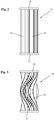
- the spring assembly 17 is arranged in the embodiment shown of two in series, in the FIGS. 2 and 3 separately shown spring units 18, each containing a plurality between two annular spring receiving 27 and 28 and formed as buckling spring elements 29 included.
- the rod-shaped spring elements 29 may be made of metal, fiberglass, CFRP or another fiber composite material and have a rectangular cross-section. They may, for example, be arranged in corresponding grooves on the end faces of the annular spring receiver 27 and 28. When the spring unit 18 is compressed, the rod-shaped spring elements 29 buckle relative to the in FIG. 2 shown starting position and are in the in FIG. 3 bent way shown.
- the rod-shaped spring elements 29 are spaced and aligned in the circumferential direction so that the spring elements 29 do not touch even in the compressed state of the spring unit 18.
- the spring elements 29 may be arranged to be inclined radially or at an angle to a connecting line between the center and the edge of the annular spring receiver 27 and 28, respectively.
- the tension rod 7 has a central cylindrical part 30 adjoining the annular collar 20 at the rear end 21 of the tension rod 7 in the longitudinal direction and an adjoining, slimmer front part 31 with opposite flattenings 32.
- the outer diameter of the sleeve-shaped receiving part 24 of arranged on the slimmer front part 31 of the clamping rod 7 contact element 19 corresponds to the outer diameter of the clamping rod 7 in the middle part 30.
- the two spring units 18 are configured identically and each have a first spring receptacle 27 and a second differently designed second Spring receptacle 28, wherein arranged on the central cylindrical portion 30 of the clamping rod 7 rear spring unit 18 is rotated relative to the slimmer on the front part 31 of the tension rod 7 arranged front spring unit 18 about its longitudinal axis by 180 °, so that the two first spring seat 27th abut on the annular collar 20 at the widened rear end 21 of the clamping rod 7 and on the annular flange 22 of the contact element 19 and the two second spring retainer 28 are arranged adjacent to each other in the middle of the spring assembly 17.
- the annular first spring receptacle 27 has a passage opening 33 with an inner diameter adapted to the outer diameter of the cylindrical middle part of the tension rod 7. On the inner wall of the passage opening 33 a plurality of evenly distributed over the circumference and in the longitudinal direction of the spring receiving 27 extending grooves 34 are provided for the supply of blowing air.
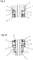
- the first spring retainer 27 also has on a front side a bore 35 for a in the FIGS. 9 and 10 shown and designed here as a locking pin securing element 36.
- passage 37 of the second spring retainer 28 has to guide the tension rod 7 has a slightly larger inner diameter than the outer diameter of the slimmer front part 31 of the tension rod 7.
- On the inner wall of the passage 37 a plurality of evenly distributed over the circumference and in the longitudinal direction of the spring receiving 28 extending grooves 40 are provided for the supply of blowing air here.
- passage opening 38 of the second spring retainer 28 are provided at the ends of the provided for the rotation parallel surfaces 39 inwardly curved grooves 41 for the passage of blowing air.
- FIG. 8 shown cross section through the contact element 19 shows that the abutment member 19 also includes a through hole 42 with two parallel surfaces 43 for abutment against the flats 32 on the slimmer front part 31 of the tension rod 7.
- the abutment element 19 has in its annular flange 22 a passage opening 44 for the in FIG. 10 shown securing element 36.
- On the outside of the annular flange 22 of the contact element 19 four circumferentially offset by 90 ° grooves 45 are provided for the supply of blowing air.
- FIG. 9 is the voltage applied to the annular collar 20 of the tension rod 7 first spring retainer 27 of arranged on the central cylindrical portion 30 of the tension rod 7 rear spring unit 18 is shown.
- pin-shaped securing element 36 engages in a recess 46 on the annular collar 20 of the clamping rod 7 a.
- the voltage applied to the annular collar 20 of the tension rod 7 first spring retainer 27 of the rear spring unit 18 is secured against rotation relative to the tension rod 7.
- FIG. 10 is the voltage applied to the contact element 19 and compared to the first spring retainer 27 of FIG. 9 around its longitudinal axis rotated by 180 ° first spring seat 27 of the arranged on the sleeve-shaped contact part 24 front spring unit 18 shown.
- the pin-shaped securing element 36 arranged in the bore 35 engages in the passage opening 44 in the annular flange 22 of the abutment element 19.
- the voltage applied to the annular flange 22 of the contact element 19 first spring seat 27 of the front spring unit 18 is secured against rotation relative to the tension rod 7.
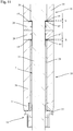
- FIG. 11 shows a detailed view of the tie rod 7 in a release position with uniformly compressed spring units 18. From this illustration it can be seen that the length of the sleeve-shaped contact part 24 of the machine part 2 supported bearing element 19 is selected so that in the release position of the tie rod 7 and ideally even Compression of both spring units 18 between a stop surface 46 at the free end of the sleeve-shaped contact part 24 and a stop surface 47 at a recess 48 of the annular second spring retainer 28 of the front spring unit 18 remains a small safety distance X remains.
- the length of the central cylindrical portion 30 of the tension rod 7 is selected so that in the release position of the tension rod 7 and ideally even compression of both spring units 18 between the stop surface 47 at the recess 48 of the annular second spring retainer 28 of the rear spring unit 18 and an annular Stop surface 49 at the transition from the central cylindrical portion 30 to the slimmer front part 31 of the tension rod 7, a small safety distance Y. remains. Thereby, the spring stroke or the axial deflection of a single spring unit 18 can be limited and thus ensured that not only one of the two spring units 18 is compressed at a caused by the displacement of the clamping rod 7 in the release position compression of the spring units 18.
- the tension rod 7 is pressed against the force of the spring assembly 17 in the direction of the tool holder 3 via the eg hydraulically, pneumatically or electrically operated release unit 25.
- the two spring elements 18 according to the FIG. 3 compressed and the forceps elements 12 of the clamping set 11 can via the clamping cone 10 and the support sleeve 16 in FIG. 1 shown, radially inwardly depressed release position.
- the outer ends 13 of the pliers elements 12 are out of engagement with the annular groove 14 in the tool holder 3 and the pliers elements 12 release the tool holder 3 for tool change.
- the clamping device according to the invention is not limited to the embodiments described above.
- the clamping system according to the invention can be used not only in hollow cone clamping systems, but also in steep taper clamping systems or other clamping systems.
- the clamping set can be used both for holding tools with hollow shank taper (HSK) and mounting tools with taper (SK) in the manner of a collet, as a clamping set for polygon clamping systems (PSC), as a clamping set with spherical clamping elements or as a clamping set for other tool changing systems be.
- PSC polygon clamping systems
- the clamping device is also suitable for the detachable mounting of workpieces.
- different drives for actuating the release unit can be used.
Landscapes
- Engineering & Computer Science (AREA)
- Mechanical Engineering (AREA)
- Jigs For Machine Tools (AREA)
- Gripping On Spindles (AREA)
- Machine Tool Units (AREA)
Applications Claiming Priority (1)
| Application Number | Priority Date | Filing Date | Title |
|---|---|---|---|
| DE102015119061.3A DE102015119061B3 (de) | 2015-11-06 | 2015-11-06 | Spannvorrichtung |
Publications (2)
| Publication Number | Publication Date |
|---|---|
| EP3165309A1 true EP3165309A1 (fr) | 2017-05-10 |
| EP3165309B1 EP3165309B1 (fr) | 2018-06-20 |
Family
ID=57208183
Family Applications (1)
| Application Number | Title | Priority Date | Filing Date |
|---|---|---|---|
| EP16195882.2A Active EP3165309B1 (fr) | 2015-11-06 | 2016-10-27 | Dispositif de serrage |
Country Status (5)
| Country | Link |
|---|---|
| US (1) | US9931700B2 (fr) |
| EP (1) | EP3165309B1 (fr) |
| JP (1) | JP6382909B2 (fr) |
| DE (1) | DE102015119061B3 (fr) |
| ES (1) | ES2687615T3 (fr) |
Families Citing this family (3)
| Publication number | Priority date | Publication date | Assignee | Title |
|---|---|---|---|---|
| US10639726B2 (en) | 2016-06-14 | 2020-05-05 | Schaublin Sa | Flexible coupling for attaching a collet to a draw bar |
| CN110052871B (zh) * | 2019-05-17 | 2020-08-18 | 廊坊市钦纵机电产品制造有限公司 | 一种旋转工件柔性驱动卡具 |
| US12103149B2 (en) | 2022-07-01 | 2024-10-01 | Toyota Motor Engineering & Manufacturing North America, Inc. | Clip installation tools |
Citations (2)
| Publication number | Priority date | Publication date | Assignee | Title |
|---|---|---|---|---|
| DE102004051031B3 (de) | 2004-10-20 | 2006-04-27 | Ott-Jakob Gmbh & Co. Spanntechnik Kg | Spannvorrichtung |
| DE102011116818A1 (de) * | 2011-10-22 | 2013-04-25 | Ott-Jakob Spanntechnik Gmbh | Löseeinheit zur Betätigung eines Spannmechanismus |
Family Cites Families (12)
| Publication number | Priority date | Publication date | Assignee | Title |
|---|---|---|---|---|
| US4790700A (en) * | 1984-07-30 | 1988-12-13 | Schwartzman Everett H | Integral spring flexure for use with high speed rotating shafts |
| JPH01146602A (ja) * | 1987-12-04 | 1989-06-08 | Mitsubishi Heavy Ind Ltd | 工具着脱装置 |
| JPH03121709A (ja) * | 1989-10-04 | 1991-05-23 | Hitachi Ltd | スピンドル装置とその工具交換方法 |
| JPH0561535U (ja) * | 1991-04-12 | 1993-08-13 | 日立精工株式会社 | さらばね |
| JP3381821B2 (ja) * | 1996-10-22 | 2003-03-04 | 株式会社牧野フライス製作所 | 主軸装置 |
| US6241224B1 (en) * | 1999-09-30 | 2001-06-05 | Xerox Corporation | Torsion spring |
| JP2001269803A (ja) * | 2000-03-27 | 2001-10-02 | Okuma Corp | 工作機械の主軸装置 |
| JP3631420B2 (ja) * | 2000-07-12 | 2005-03-23 | 株式会社キラ・コーポレーション | 高速回転用の主軸装置 |
| JP2003220504A (ja) * | 2002-01-25 | 2003-08-05 | Okuma Corp | 工作機械の主軸装置における工具固定ばね監視装置 |
| JP4250645B2 (ja) * | 2005-11-04 | 2009-04-08 | 東海バネ工業株式会社 | 皿ばね装置、並びにそれに用いるガイド軸及び皿ばね |
| JP4715820B2 (ja) * | 2007-08-14 | 2011-07-06 | 日本精工株式会社 | 主軸装置 |
| DE102014117571B3 (de) * | 2014-12-01 | 2016-02-18 | Ott-Jakob Spanntechnik Gmbh | Spannvorrichtung |
-
2015
- 2015-11-06 DE DE102015119061.3A patent/DE102015119061B3/de not_active Expired - Fee Related
-
2016
- 2016-10-27 EP EP16195882.2A patent/EP3165309B1/fr active Active
- 2016-10-27 US US15/335,673 patent/US9931700B2/en not_active Expired - Fee Related
- 2016-10-27 ES ES16195882.2T patent/ES2687615T3/es active Active
- 2016-10-28 JP JP2016211309A patent/JP6382909B2/ja not_active Expired - Fee Related
Patent Citations (2)
| Publication number | Priority date | Publication date | Assignee | Title |
|---|---|---|---|---|
| DE102004051031B3 (de) | 2004-10-20 | 2006-04-27 | Ott-Jakob Gmbh & Co. Spanntechnik Kg | Spannvorrichtung |
| DE102011116818A1 (de) * | 2011-10-22 | 2013-04-25 | Ott-Jakob Spanntechnik Gmbh | Löseeinheit zur Betätigung eines Spannmechanismus |
Also Published As
| Publication number | Publication date |
|---|---|
| JP6382909B2 (ja) | 2018-08-29 |
| US20170129019A1 (en) | 2017-05-11 |
| US9931700B2 (en) | 2018-04-03 |
| ES2687615T3 (es) | 2018-10-26 |
| JP2017136679A (ja) | 2017-08-10 |
| EP3165309B1 (fr) | 2018-06-20 |
| DE102015119061B3 (de) | 2016-12-15 |
Similar Documents
| Publication | Publication Date | Title |
|---|---|---|
| EP2812142B1 (fr) | Outil à visser et logement d'outil pour un tel outil à visser | |
| DE102010004526B4 (de) | Zerspanungswerkzeug | |
| EP1961507B1 (fr) | Dispositif de serrage | |
| CH655892A5 (de) | Bohrhammer mit fuehrungszylinder fuer das schlagwerk. | |
| EP3165310B1 (fr) | Dispositif de serrage | |
| DE2744410A1 (de) | 4-backen-spannfutter fuer ein werkstueck | |
| EP3178591B1 (fr) | Kit de serrage et dispositif de serrage comprenant un tel kit de serrage | |
| EP3165309B1 (fr) | Dispositif de serrage | |
| EP2879824B1 (fr) | Adaptateur d'équilibrage ou de mesure | |
| EP3385016A1 (fr) | Dispositif de serrage et unité d'usinage dotée d'un tel dispositif de serrage | |
| DE102017000671B4 (de) | Drehfutter und Werkzeugmaschine | |
| EP1663555B1 (fr) | Dispositif de serrage | |
| EP3292932B1 (fr) | Ensemble à ressort permettant de générer la force de serrage d'un dispositif de serrage et dispositif de serrage pourvu d'un tel ensemble à ressort | |
| DE19831743B4 (de) | Vorrichtung zum Bearbeiten von Werkstücken | |
| EP3028795B1 (fr) | Dispositif de serrage | |
| EP2910325B1 (fr) | Tourelle revolver | |
| EP4035811A1 (fr) | Moyen de serrage et bague de réduction associée | |
| EP2103367A1 (fr) | Dispositif de serrage pour objets, par exemple pour des pièces usinées devant être traitées | |
| DE102019103238B3 (de) | Spannvorrichtung mit einer Federanordnung | |
| EP4155015A1 (fr) | Dispositif de serrage pour un outil ou une pièce à usiner doté d'une pince de serrage et d'un élément de serrage pour un dispositif de serrage et procédé de serrage d'un dispositif de serrage ou de serrage | |
| DE102011119434B4 (de) | Spannvorrichtung und Werkzeughalter mit einer derartigen Spannvorrichtung | |
| DE202007014828U1 (de) | Spannfutter für zu spannende Teile | |
| DE3700841A1 (de) | Kupplungselement, insbesondere zum kraft- und formschluessigen verbinden eines werkzeugkopfes mit einem werkzeugtraeger | |
| DE202023100799U1 (de) | Spannvorrichtung mit elastischem axialem Längenausgleich und elastisches Element für eine solche Spannvorrichtung | |
| DE102023136700A1 (de) | Universelles Spannsystem |
Legal Events
| Date | Code | Title | Description |
|---|---|---|---|
| PUAI | Public reference made under article 153(3) epc to a published international application that has entered the european phase |
Free format text: ORIGINAL CODE: 0009012 |
|
| AK | Designated contracting states |
Kind code of ref document: A1 Designated state(s): AL AT BE BG CH CY CZ DE DK EE ES FI FR GB GR HR HU IE IS IT LI LT LU LV MC MK MT NL NO PL PT RO RS SE SI SK SM TR |
|
| AX | Request for extension of the european patent |
Extension state: BA ME |
|
| 17P | Request for examination filed |
Effective date: 20171110 |
|
| RBV | Designated contracting states (corrected) |
Designated state(s): AL AT BE BG CH CY CZ DE DK EE ES FI FR GB GR HR HU IE IS IT LI LT LU LV MC MK MT NL NO PL PT RO RS SE SI SK SM TR |
|
| GRAP | Despatch of communication of intention to grant a patent |
Free format text: ORIGINAL CODE: EPIDOSNIGR1 |
|
| INTG | Intention to grant announced |
Effective date: 20180226 |
|
| GRAS | Grant fee paid |
Free format text: ORIGINAL CODE: EPIDOSNIGR3 |
|
| GRAA | (expected) grant |
Free format text: ORIGINAL CODE: 0009210 |
|
| AK | Designated contracting states |
Kind code of ref document: B1 Designated state(s): AL AT BE BG CH CY CZ DE DK EE ES FI FR GB GR HR HU IE IS IT LI LT LU LV MC MK MT NL NO PL PT RO RS SE SI SK SM TR |
|
| REG | Reference to a national code |
Ref country code: GB Ref legal event code: FG4D Free format text: NOT ENGLISH |
|
| REG | Reference to a national code |
Ref country code: IE Ref legal event code: FG4D Free format text: LANGUAGE OF EP DOCUMENT: GERMAN |
|
| REG | Reference to a national code |
Ref country code: DE Ref legal event code: R096 Ref document number: 502016001287 Country of ref document: DE |
|
| REG | Reference to a national code |
Ref country code: AT Ref legal event code: REF Ref document number: 1010218 Country of ref document: AT Kind code of ref document: T Effective date: 20180715 |
|
| REG | Reference to a national code |
Ref country code: FR Ref legal event code: PLFP Year of fee payment: 3 |
|
| REG | Reference to a national code |
Ref country code: NL Ref legal event code: MP Effective date: 20180620 |
|
| REG | Reference to a national code |
Ref country code: ES Ref legal event code: FG2A Ref document number: 2687615 Country of ref document: ES Kind code of ref document: T3 Effective date: 20181026 |
|
| PG25 | Lapsed in a contracting state [announced via postgrant information from national office to epo] |
Ref country code: LT Free format text: LAPSE BECAUSE OF FAILURE TO SUBMIT A TRANSLATION OF THE DESCRIPTION OR TO PAY THE FEE WITHIN THE PRESCRIBED TIME-LIMIT Effective date: 20180620 Ref country code: NO Free format text: LAPSE BECAUSE OF FAILURE TO SUBMIT A TRANSLATION OF THE DESCRIPTION OR TO PAY THE FEE WITHIN THE PRESCRIBED TIME-LIMIT Effective date: 20180920 Ref country code: BG Free format text: LAPSE BECAUSE OF FAILURE TO SUBMIT A TRANSLATION OF THE DESCRIPTION OR TO PAY THE FEE WITHIN THE PRESCRIBED TIME-LIMIT Effective date: 20180920 Ref country code: SE Free format text: LAPSE BECAUSE OF FAILURE TO SUBMIT A TRANSLATION OF THE DESCRIPTION OR TO PAY THE FEE WITHIN THE PRESCRIBED TIME-LIMIT Effective date: 20180620 Ref country code: FI Free format text: LAPSE BECAUSE OF FAILURE TO SUBMIT A TRANSLATION OF THE DESCRIPTION OR TO PAY THE FEE WITHIN THE PRESCRIBED TIME-LIMIT Effective date: 20180620 |
|
| REG | Reference to a national code |
Ref country code: LT Ref legal event code: MG4D |
|
| PG25 | Lapsed in a contracting state [announced via postgrant information from national office to epo] |
Ref country code: LV Free format text: LAPSE BECAUSE OF FAILURE TO SUBMIT A TRANSLATION OF THE DESCRIPTION OR TO PAY THE FEE WITHIN THE PRESCRIBED TIME-LIMIT Effective date: 20180620 Ref country code: GR Free format text: LAPSE BECAUSE OF FAILURE TO SUBMIT A TRANSLATION OF THE DESCRIPTION OR TO PAY THE FEE WITHIN THE PRESCRIBED TIME-LIMIT Effective date: 20180921 Ref country code: HR Free format text: LAPSE BECAUSE OF FAILURE TO SUBMIT A TRANSLATION OF THE DESCRIPTION OR TO PAY THE FEE WITHIN THE PRESCRIBED TIME-LIMIT Effective date: 20180620 Ref country code: RS Free format text: LAPSE BECAUSE OF FAILURE TO SUBMIT A TRANSLATION OF THE DESCRIPTION OR TO PAY THE FEE WITHIN THE PRESCRIBED TIME-LIMIT Effective date: 20180620 |
|
| PG25 | Lapsed in a contracting state [announced via postgrant information from national office to epo] |
Ref country code: NL Free format text: LAPSE BECAUSE OF FAILURE TO SUBMIT A TRANSLATION OF THE DESCRIPTION OR TO PAY THE FEE WITHIN THE PRESCRIBED TIME-LIMIT Effective date: 20180620 |
|
| PG25 | Lapsed in a contracting state [announced via postgrant information from national office to epo] |
Ref country code: CZ Free format text: LAPSE BECAUSE OF FAILURE TO SUBMIT A TRANSLATION OF THE DESCRIPTION OR TO PAY THE FEE WITHIN THE PRESCRIBED TIME-LIMIT Effective date: 20180620 Ref country code: SK Free format text: LAPSE BECAUSE OF FAILURE TO SUBMIT A TRANSLATION OF THE DESCRIPTION OR TO PAY THE FEE WITHIN THE PRESCRIBED TIME-LIMIT Effective date: 20180620 Ref country code: IS Free format text: LAPSE BECAUSE OF FAILURE TO SUBMIT A TRANSLATION OF THE DESCRIPTION OR TO PAY THE FEE WITHIN THE PRESCRIBED TIME-LIMIT Effective date: 20181020 Ref country code: PL Free format text: LAPSE BECAUSE OF FAILURE TO SUBMIT A TRANSLATION OF THE DESCRIPTION OR TO PAY THE FEE WITHIN THE PRESCRIBED TIME-LIMIT Effective date: 20180620 Ref country code: EE Free format text: LAPSE BECAUSE OF FAILURE TO SUBMIT A TRANSLATION OF THE DESCRIPTION OR TO PAY THE FEE WITHIN THE PRESCRIBED TIME-LIMIT Effective date: 20180620 Ref country code: RO Free format text: LAPSE BECAUSE OF FAILURE TO SUBMIT A TRANSLATION OF THE DESCRIPTION OR TO PAY THE FEE WITHIN THE PRESCRIBED TIME-LIMIT Effective date: 20180620 |
|
| PG25 | Lapsed in a contracting state [announced via postgrant information from national office to epo] |
Ref country code: SM Free format text: LAPSE BECAUSE OF FAILURE TO SUBMIT A TRANSLATION OF THE DESCRIPTION OR TO PAY THE FEE WITHIN THE PRESCRIBED TIME-LIMIT Effective date: 20180620 |
|
| REG | Reference to a national code |
Ref country code: DE Ref legal event code: R097 Ref document number: 502016001287 Country of ref document: DE |
|
| PLBE | No opposition filed within time limit |
Free format text: ORIGINAL CODE: 0009261 |
|
| STAA | Information on the status of an ep patent application or granted ep patent |
Free format text: STATUS: NO OPPOSITION FILED WITHIN TIME LIMIT |
|
| 26N | No opposition filed |
Effective date: 20190321 |
|
| PG25 | Lapsed in a contracting state [announced via postgrant information from national office to epo] |
Ref country code: DK Free format text: LAPSE BECAUSE OF FAILURE TO SUBMIT A TRANSLATION OF THE DESCRIPTION OR TO PAY THE FEE WITHIN THE PRESCRIBED TIME-LIMIT Effective date: 20180620 |
|
| REG | Reference to a national code |
Ref country code: BE Ref legal event code: MM Effective date: 20181031 |
|
| PG25 | Lapsed in a contracting state [announced via postgrant information from national office to epo] |
Ref country code: LU Free format text: LAPSE BECAUSE OF NON-PAYMENT OF DUE FEES Effective date: 20181027 Ref country code: MC Free format text: LAPSE BECAUSE OF FAILURE TO SUBMIT A TRANSLATION OF THE DESCRIPTION OR TO PAY THE FEE WITHIN THE PRESCRIBED TIME-LIMIT Effective date: 20180620 |
|
| REG | Reference to a national code |
Ref country code: IE Ref legal event code: MM4A |
|
| PG25 | Lapsed in a contracting state [announced via postgrant information from national office to epo] |
Ref country code: SI Free format text: LAPSE BECAUSE OF FAILURE TO SUBMIT A TRANSLATION OF THE DESCRIPTION OR TO PAY THE FEE WITHIN THE PRESCRIBED TIME-LIMIT Effective date: 20180620 Ref country code: BE Free format text: LAPSE BECAUSE OF NON-PAYMENT OF DUE FEES Effective date: 20181031 |
|
| PG25 | Lapsed in a contracting state [announced via postgrant information from national office to epo] |
Ref country code: IE Free format text: LAPSE BECAUSE OF NON-PAYMENT OF DUE FEES Effective date: 20181027 |
|
| PG25 | Lapsed in a contracting state [announced via postgrant information from national office to epo] |
Ref country code: AL Free format text: LAPSE BECAUSE OF FAILURE TO SUBMIT A TRANSLATION OF THE DESCRIPTION OR TO PAY THE FEE WITHIN THE PRESCRIBED TIME-LIMIT Effective date: 20180620 |
|
| PG25 | Lapsed in a contracting state [announced via postgrant information from national office to epo] |
Ref country code: MT Free format text: LAPSE BECAUSE OF FAILURE TO SUBMIT A TRANSLATION OF THE DESCRIPTION OR TO PAY THE FEE WITHIN THE PRESCRIBED TIME-LIMIT Effective date: 20180620 |
|
| PG25 | Lapsed in a contracting state [announced via postgrant information from national office to epo] |
Ref country code: TR Free format text: LAPSE BECAUSE OF FAILURE TO SUBMIT A TRANSLATION OF THE DESCRIPTION OR TO PAY THE FEE WITHIN THE PRESCRIBED TIME-LIMIT Effective date: 20180620 |
|
| PG25 | Lapsed in a contracting state [announced via postgrant information from national office to epo] |
Ref country code: PT Free format text: LAPSE BECAUSE OF FAILURE TO SUBMIT A TRANSLATION OF THE DESCRIPTION OR TO PAY THE FEE WITHIN THE PRESCRIBED TIME-LIMIT Effective date: 20180620 |
|
| PG25 | Lapsed in a contracting state [announced via postgrant information from national office to epo] |
Ref country code: HU Free format text: LAPSE BECAUSE OF FAILURE TO SUBMIT A TRANSLATION OF THE DESCRIPTION OR TO PAY THE FEE WITHIN THE PRESCRIBED TIME-LIMIT; INVALID AB INITIO Effective date: 20161027 Ref country code: MK Free format text: LAPSE BECAUSE OF NON-PAYMENT OF DUE FEES Effective date: 20180620 Ref country code: CY Free format text: LAPSE BECAUSE OF FAILURE TO SUBMIT A TRANSLATION OF THE DESCRIPTION OR TO PAY THE FEE WITHIN THE PRESCRIBED TIME-LIMIT Effective date: 20180620 |
|
| PGFP | Annual fee paid to national office [announced via postgrant information from national office to epo] |
Ref country code: IT Payment date: 20201030 Year of fee payment: 5 Ref country code: ES Payment date: 20201117 Year of fee payment: 5 Ref country code: FR Payment date: 20201020 Year of fee payment: 5 Ref country code: CH Payment date: 20201022 Year of fee payment: 5 Ref country code: GB Payment date: 20201022 Year of fee payment: 5 |
|
| REG | Reference to a national code |
Ref country code: CH Ref legal event code: PL |
|
| GBPC | Gb: european patent ceased through non-payment of renewal fee |
Effective date: 20211027 |
|
| PG25 | Lapsed in a contracting state [announced via postgrant information from national office to epo] |
Ref country code: GB Free format text: LAPSE BECAUSE OF NON-PAYMENT OF DUE FEES Effective date: 20211027 |
|
| PG25 | Lapsed in a contracting state [announced via postgrant information from national office to epo] |
Ref country code: LI Free format text: LAPSE BECAUSE OF NON-PAYMENT OF DUE FEES Effective date: 20211031 Ref country code: CH Free format text: LAPSE BECAUSE OF NON-PAYMENT OF DUE FEES Effective date: 20211031 |
|
| PG25 | Lapsed in a contracting state [announced via postgrant information from national office to epo] |
Ref country code: FR Free format text: LAPSE BECAUSE OF NON-PAYMENT OF DUE FEES Effective date: 20211031 |
|
| PG25 | Lapsed in a contracting state [announced via postgrant information from national office to epo] |
Ref country code: IT Free format text: LAPSE BECAUSE OF NON-PAYMENT OF DUE FEES Effective date: 20211027 |
|
| REG | Reference to a national code |
Ref country code: AT Ref legal event code: MM01 Ref document number: 1010218 Country of ref document: AT Kind code of ref document: T Effective date: 20211027 |
|
| PG25 | Lapsed in a contracting state [announced via postgrant information from national office to epo] |
Ref country code: AT Free format text: LAPSE BECAUSE OF NON-PAYMENT OF DUE FEES Effective date: 20211027 |
|
| REG | Reference to a national code |
Ref country code: ES Ref legal event code: FD2A Effective date: 20230207 |
|
| PG25 | Lapsed in a contracting state [announced via postgrant information from national office to epo] |
Ref country code: ES Free format text: LAPSE BECAUSE OF NON-PAYMENT OF DUE FEES Effective date: 20211028 |
|
| PGFP | Annual fee paid to national office [announced via postgrant information from national office to epo] |
Ref country code: DE Payment date: 20251106 Year of fee payment: 10 |