EP3165685A1 - Schachtanordnung - Google Patents
Schachtanordnung Download PDFInfo
- Publication number
- EP3165685A1 EP3165685A1 EP16202693.4A EP16202693A EP3165685A1 EP 3165685 A1 EP3165685 A1 EP 3165685A1 EP 16202693 A EP16202693 A EP 16202693A EP 3165685 A1 EP3165685 A1 EP 3165685A1
- Authority
- EP
- European Patent Office
- Prior art keywords
- shaft
- arrangement according
- lid
- shaft arrangement
- housing
- Prior art date
- Legal status (The legal status is an assumption and is not a legal conclusion. Google has not performed a legal analysis and makes no representation as to the accuracy of the status listed.)
- Granted
Links
Images

Classifications
-
- E—FIXED CONSTRUCTIONS
- E03—WATER SUPPLY; SEWERAGE
- E03B—INSTALLATIONS OR METHODS FOR OBTAINING, COLLECTING, OR DISTRIBUTING WATER
- E03B9/00—Methods or installations for drawing-off water
- E03B9/02—Hydrants; Arrangements of valves therein; Keys for hydrants
- E03B9/08—Underground hydrants
- E03B9/10—Protective plates or covers
-
- E—FIXED CONSTRUCTIONS
- E02—HYDRAULIC ENGINEERING; FOUNDATIONS; SOIL SHIFTING
- E02D—FOUNDATIONS; EXCAVATIONS; EMBANKMENTS; UNDERGROUND OR UNDERWATER STRUCTURES
- E02D29/00—Independent underground or underwater structures; Retaining walls
- E02D29/12—Manhole shafts; Other inspection or access chambers; Accessories therefor
- E02D29/14—Covers for manholes or the like; Frames for covers
-
- E—FIXED CONSTRUCTIONS
- E03—WATER SUPPLY; SEWERAGE
- E03B—INSTALLATIONS OR METHODS FOR OBTAINING, COLLECTING, OR DISTRIBUTING WATER
- E03B7/00—Water main or service pipe systems
- E03B7/09—Component parts or accessories
- E03B7/095—Component holders or housings, e.g. boundary boxes
-
- B—PERFORMING OPERATIONS; TRANSPORTING
- B05—SPRAYING OR ATOMISING IN GENERAL; APPLYING FLUENT MATERIALS TO SURFACES, IN GENERAL
- B05B—SPRAYING APPARATUS; ATOMISING APPARATUS; NOZZLES
- B05B15/00—Details of spraying plant or spraying apparatus not otherwise provided for; Accessories
- B05B15/14—Arrangements for preventing or controlling structural damage to spraying apparatus or its outlets, e.g. for breaking at desired places; Arrangements for handling or replacing damaged parts
- B05B15/16—Arrangements for preventing or controlling structural damage to spraying apparatus or its outlets, e.g. for breaking at desired places; Arrangements for handling or replacing damaged parts for preventing non-intended contact between spray heads or nozzles and foreign bodies, e.g. nozzle guards
Definitions
- the invention relates to a shaft arrangement of a garden irrigation system.
- an upwardly pointing shaft opening is typically closable by a cover which can be pivoted about a pivot joint in order to release the shaft opening.
- the manhole cover rests against the manhole housing along an edge curve and is typically also vertically supported on the manhole housing via this boundary curve.
- the manhole cover is designed in a stability that allows the entry of the manhole cover by a person without destroying the manhole cover.
- stiffening ribs can be provided here on the downwardly facing side of the manhole cover.
- Common manhole structures exhibit various susceptibility to damage, for example by sucking an unlocked closed lid when driving over with a lawnmower or damage an upwardly protruding open manhole cover during the connection of a hose to a tapping point arranged in the shaft.
- the object of the present invention is to specify a shaft arrangement of a garden irrigation system which is improved, in particular with regard to the risk of damage to the cover arrangement.
- the projection of the manhole cover over the manhole housing in the open position is at least considerably reduced, in a preferred embodiment substantially eliminated altogether.
- the pivot axis is arranged below the edge curve and positioned in vertical projection within the projection surface of the shaft opening.
- the terms horizontal and vertical are based on the orientation of the shaft assembly in its regular installation position in the ground.
- the lid surface is advantageously against the edge curve, as which in the closed position of the lid on the shaft top between the movable Cover and the fixed housing part is approximately linear contact surface is understood, curved upwards, which gives the lid increased stability against treading.
- the cover surface is extended by means of joint supports to the deeper pivot joint.
- the pivot joint advantageously has a comparison with known arrangements large joint sliding surface about the pivot axis whose radius is advantageously at least 10% of the maximum diameter of the visible in the closed state lid surface or the shaft opening with the lid open.
- the storage of the lid in the pivot joint may advantageously be designed such that the lid quickly gains a distance from the previously applied to the lid fixed boundary at the opening movement, with a distance of one or a few millimeters inclined to a lingering of the lid on the Boundary with the risk of scratching by hard earth particles to avoid.
- a movement which advantageously differ from a pure rotational movement to a pivot joint and can cause a faster slight lowering of the lid on the boundary, z.
- a guide curve, a lever joint, a decentration of the pivot axis, etc. be used advantageously.
- the annular surface is advantageously part of an insert body which is detachably inserted into a shaft housing remaining permanently in the bottom, advantageously the pivot joint, about which the lid is pivotable, is formed between the insert body and a cover body containing the lid body.
- a holding device which applies a manually surmountable holding force in the closed position of the lid and can be designed as a clamp or preferably as a latch, is advantageously arranged in the hinge arrangement and thus in a position largely protected from the action of UV radiation.
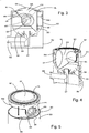
- Fig. 1 shows an oblique view from above of a shaft assembly according to the invention
- the shaft housing SG is divided into an upper portion SO with a substantially circular cylindrical wall and one below a section SU.
- the housing wall is substantially a circular cylindrical lateral surface forms and in the lower housing portion SU of the shaft bottom SB, which limits the interior of the shaft assembly down, from the outer wall down to the center down.
- the shaft bottom SB can advantageously have a curved shape, as shown, but can also assume other shapes and in particular also run flat.
- the shaft arrangement is closed at the top by an annular surface RF and a cover surface DF.
- the annular surface RF is part of an insert body which rests with a vertically downwardly extending wall RW within the wall of the upper portion SO of the manhole housing and advantageously with a radially outwardly projecting projection of the annular surface beyond the wall RW on the upper edge of the manhole housing section SO supported.
- the radial width of the annular surface RF in the radial direction relative to the central axis MA is advantageously at least 10% of the outer diameter of the annular body, which in the case outlined is substantially equal to the outer diameter of the shaft housing.
- a radial distance of the lid surface or the covered by this opening of the surrounding soil and plant area reduces the risk that earth particles fall into the interior of the shaft or that when closing the lid parts of plants are trapped and the lid does not close properly.
- the cover surface DF forms in Fig. 1 and Fig. 2 illustrated closed state of the lid, the upward-facing, visible to the user surface of the lid, which rests along a designated hereinafter as edge curve, approximately linear surface on the annular surface RF and covers the surrounded by the annular surface RF shaft opening.
- the cover surface RF can extend slightly below or above the annular surface in the region of the shaft opening.
- a gripping tab HL Connected to the lid surface is an extension in the form of a gripping tab HL, which serves as a starting point for a finger of a user to open the lid by the lid is pivoted at the gripping tab HL upwards.
- the lid is lowered at the same time against the inside of the shaft housing at its portion lying opposite the gripping bottle HL with respect to the central axis MA.
- Fig. 4 is one of the Fig. 2 corresponding view shown in fully pivoted in the open position lid, in which the lid surface. DF is substantially completely lowered into the interior of the shaft housing and only the grip tab GL protrudes beyond the annular surface and serves as a handle attachment for closing the lid.
- the cover advantageously contains, in continuation of the cover surface, articulated supports GS which lie opposite the ends of the cover surface with respect to the pivot axis SA, which support the cover-side parts of a pivot joint arrangement and can in particular be embodied with these and the cover surface DF as a one-piece plastic injection-molded body.
- the joint supports GS advantageously serve at the same time to transmit a force acting on the cover surface force, in particular when entering the cover surface DF by a person, on the pivot joint assembly on the shaft housing.
- the pivot joint arrangement is formed between the cover surface in the stated embodiment with joint supports continued from the cover surface DF on the one hand and an insert body which also contains the wall RW and the annular surface RF as a one-piece plastic injection molded body.
- Fig. 5 shows such insert body in conjunction with a lid assembly in lifted from the upper portion SO of the shaft housing position.
- the pivot joint assembly includes in two in the direction of the pivot axis SA oppositely arranged pivot joints each formed on sides of the insert body hinge bushing GB, in which a formed on the associated joint support GS of the cover assembly joint socket GA rotatably rests.
- the contact surface between the joint socket GA and the joint bush GB advantageously has a radius which amounts to at least 10% of the largest diameter of the shaft opening surrounded by the annular surface RF.
- a large radius results in a large support surface of the joint socket GA against the hinge bushing GB when a tread load of the lid surface and a distribution of force on such a large support surface with a correspondingly lower surface load in the pivot joint.
- the lower edge of the joint bushing is supported on an inwardly projecting step SS inside the shaft housing.
- the cover surface is advantageously curved in its surrounded by the annular surface RF portion opposite said edge curve RK upwards, which also results in a favorable force distribution at tread load of the lid surface.
- the cover surface DF lies with its predominant surface portion advantageously closer to the pivot axis SA than the radial distance of the edge curve RK from the pivot axis SA at the respective associated axial position for the shaft opening at the immersing under the edge curve side of the lid.
- the top surface is therefore flattened. This creates when pivoting the lid and immersing the lid surface DF in the shaft interior during the pivoting operation, a gap between the lid surface DF and the shaft opening RK and possibly located in the shaft opening RK hard particles do not lead to scratching the lid surface and may optionally in the shaft interior fall and block then not the closing process.
- a softer material can also be provided along the edge curve, which can be attached in particular to the inner edge of the annular surface in the 2K injection molding process. A soft material can reduce the risk of scratching the lid surface and the ingress of water.
- An angle of the in a central longitudinal plane according to the cutting planes after Fig. 2 to Fig. 4 between radii from the pivot axis to opposite points of the shaft opening is in Fig. 3 designated WR.
- the angle WR is advantageously at least 60 ° and / or at most 120 °. Preferably, the angle WR is about 90 °.
- the swing angle, by which the lid between the in Fig. 2 shown closed position and in Fig. 4 shown opening position is pivotable about the pivot axis, is advantageously also at least 60% and / or at most 120%.
- the pivot angle between the closed position and the open position is preferably about 90 °.
- the lid may advantageously be held in the closed position by an additional holding device with a manually surmountable holding force, wherein the holding device may form, for example, a clamping device or preferably a latching.
- a latching is advantageously made of plastic and arranged on a UV radiation largely protected place and is in the in Fig. 5 illustrated preferred example formed in the region of the pivot joint assembly.
- a latching can for example be given by a resilient web FR on the insert body, which forms a counter-structure to a latching structure connected to the cover-side part of the pivot joint.
- a projection formed on the axle stub GA is opposed to a projection formed on the spring bar FR held the pivot axis SA aligned further projection latching.
- a holding device may advantageously also include a magnet arrangement.
- the lid assembly advantageously has a bow BO leading from the lid surface DF beyond the joint supports GS, which stabilizes the lid body in its shape.
- the bow BO is in the closed position of the lid facing down inside the shaft and surrounds in the in Fig. 4 illustrated opening position of the lid enclosed by the annular surface RF shaft opening on the lid surface DF opposite side.
- a functional device which can be arranged in the shaft housing, is advantageously positioned in the center of the shaft at the central axis MA and thus easily accessible by the open in the open position of the lid shaft opening.
- a functional device which z. B. may be an optionally lockable coupling piece of a plug-in coupling system can be advantageously held in the shaft via a connection device in the shaft interior.
- a connection device may in particular be a connecting piece ST connected in a water-conducting manner to an underground water inlet WE.
- the functional device can also be replaced by various other elements, such. B. a electromagnetic or manually operated valve, rolled up hose, etc.
- the shaft bottom SB can advantageously be carried out from the outer wall of the shaft housing forth towards the center falling, in particular curved curved.
- the shaft bottom may advantageously contain drainage and ventilation openings, in the sketched example in the form of radially extending slots AS.
- the width of the slots or generally the diameter of such bottom openings is advantageously less than 1 mm, in particular less than 0.5 mm, in order to prevent the penetration of insects in the shaft interior as possible.
- Cleaning of the interior of the shaft can in particular be achieved by the combination of the insert body and the cover, which can be removed as a unit, as in FIG Fig. 5 shown, since then an access into the shaft interior through the enlarged opening with the diameter of the cylindrical wall of the upper shaft housing portion SO is given.
- the shaft bottom can be formed or covered by a removable insert.
Landscapes
- Engineering & Computer Science (AREA)
- Life Sciences & Earth Sciences (AREA)
- Health & Medical Sciences (AREA)
- Hydrology & Water Resources (AREA)
- Public Health (AREA)
- Water Supply & Treatment (AREA)
- Mining & Mineral Resources (AREA)
- General Life Sciences & Earth Sciences (AREA)
- Environmental & Geological Engineering (AREA)
- Paleontology (AREA)
- Civil Engineering (AREA)
- General Engineering & Computer Science (AREA)
- Structural Engineering (AREA)
- Underground Structures, Protecting, Testing And Restoring Foundations (AREA)
- Closures For Containers (AREA)
- Sink And Installation For Waste Water (AREA)
- Domestic Plumbing Installations (AREA)
- Harvester Elements (AREA)
Abstract
Description
- Die Erfindung betrifft eine Schachtanordnung eines Gartenbewässerungssystems.
- Bei Gartenbewässerungssystemen ist es gebräuchlich, fest installierte Leitungen, typischerweise Kunststoffrohre, im Erdboden zu verlegen und Funktionseinheiten, wie insbesondere Anschlussstellen in Schachtgehäusen, welche in die Erde eingegraben sind, unterzubringen. Solche Funktionseinheiten können beispielsweise Ventile oder Zapfstellen enthalten.
- Um Zugang zu den im Schachtgehäuse angeordneten Anschlussstellen zu haben, ist typischerweise eine nach oben weisende Schachtöffnung durch einen Deckel verschließbar, welcher um ein Schwenkgelenk verschwenkbar ist, um die Schachtöffnung frei zu geben. Der Schachtdeckel liegt entlang einer Randkurve an dem Schachtgehäuse an und ist typischerweise auch über diese Randkurve vertikal an dem Schachtgehäuse abgestützt. Der Schachtdeckel ist in einer Stabilität ausgeführt, welche das Betreten des Schachtdeckels durch eine Person ohne Zerstörung des Schachtdeckels zuläßt. Typischerweise können hier an der nach unten weisenden Seite des Schachtdeckels Aussteifungsrippen vorgesehen sein.
- Gebräuchliche Schachtanordnungen zeigen verschiedene Anfälligkeiten gegen Beschädigung, beispielsweise durch Ansaugen eines nicht arretierten geschlossenen Deckels beim Überfahren mit einem Rasenmäher oder Beschädigung eines nach oben abstehenden geöffneten Schachtdeckels während des Anschlusses eines Schlauches an eine im Schacht angeordnete Zapfstelle. Der vorliegenden Erfindung liegt die Aufgabe zugrunde, eine insbesondere hinsichtlich der Beschädigungsgefahr der Deckelanordnung verbesserte Schachtanordnung eines Gartenbewässerungssystems anzugeben.
- Die Erfindung ist im Anspruch 1 beschrieben. Die abhängigen Ansprüche enthalten vorteilhafte Ausgestaltungen und Weiterbildungen der Erfindung.
- Durch die zumindest teilweise Verlagerung der Deckelfläche des Schachtdeckels in dessen Öffnungsstellung ins Schachtinnere wird der Überstand des Schachtdeckels über das Schachtgehäuse in der Öffnungsstellung zumindest erheblich verringert, in bevorzugter Ausführung im wesentlichen ganz beseitigt.
- Vorteilhafterweise wird die Schwenkachse unterhalb der Randkurve angeordnet und in vertikaler Projektion innerhalb der Projektionsfläche der Schachtöffnung positioniert. Dies führt gegenüber den bekannten Schachtdeckelanordnungen mit am Rande des Schachtes angeordnetem Schwenkgelenk und in Öffnungsstellung vollständig oberhalb der Randkurve befindlichem Schachtdeckel zu einer anderen Lagerung und Schwenkbewegung des Schachtdeckels. Insbesondere entfällt die Gefahr eines unbeabsichtigten Öffnens des Schachtdeckels durch einen von einem Rasenmäher erzeugten Unterdruck dadurch, dass ein solcher Unterdruck auf verschiedene Flächenabschnitte der Deckelfläche bezüglich einer Verschwenkung entgegen gesetzt wirkt und sich damit quasi neutralisiert.
- Die Begriffe horizontal und vertikal sind auf die Ausrichtung der Schachtanordnung in deren regulärer Einbaulage im Erdboden bezogen.
- Die Deckelfläche ist vorteilhafterweise gegen die Randkurve, als welche die in der Schließstellung des Deckels an der Schachtoberseite zwischen dem beweglichen Deckel und dem feststehenden Gehäuseteil annähernd linienförmige Anlagefläche verstanden sei, nach oben gewölbt, was dem Deckel eine erhöhte Stabilität gegen Trittbelastung verleiht. Vorteilhafterweise ist die Deckelfläche über Gelenkstützen zu dem tiefer angeordneten Schwenkgelenk hin verlängert. Das Schwenkgelenk besitzt vorteilhafterweise eine gegenüber bekannten Anordnungen große Gelenkgleitfläche um die Schwenkachse, deren Radius vorteilhafterweise wenigstens 10 % des maximalen Durchmessers der im geschlossenen Zustand sichtbaren Deckelfläche oder der Schachtöffnung bei geöffnetem Deckel beträgt.
- Die Lagerung des Deckels in dem Schwenkgelenk kann vorteilhafterweise derart gestaltet sein, dass der Deckel bei der Öffnungsbewegung schnell einen Abstand von der zuvor an dem Deckel anliegenden feststehenden Berandung gewinnt, wobei ein Abstand von einem oder wenigen Millimetern geneigt, um ein Entlangstreifen des Deckels an der Berandung mit der Gefahr des Zerkratzens durch harte Erdpartikel zu vermeiden. Für eine solche Bewegung welche vorteilhafterweise von einer reinen Rotationsbewegung, um ein Schwenkgelenk abweichen und ein schnelleres geringfügiges Absenken des Deckels an der Berandung bewirken kann, kann z. B. eine Führungskurve, ein Hebelgelenk, eine Dezentrierung der Schwenkachse etc. vorteilhaft einsetzbar sein.
- Vorteilhafterweise ist die Deckelfläche im geschlossenen Zustand des Deckels bzw. die frei gegebene Öffnung im geöffneten Zustand des Deckels von dem Außenrand der Schachtanordnung durch eine Ringfläche um wenigstens 10 % des Durchmessers der Oberseite der Schachtanordnung beabstandet. Hierdurch kann insbesondere die Gefahr des Einfallens von Erdpartikeln oder das Einklemmen von Gras aus der Umgebung verringert werden. Die Ringfläche ist vorteilhafterweise Teil eines Einsatzkörpers, der abnehmbar in ein dauerhaft in dem Boden verbleibendes Schachtgehäuse eingesetzt ist, wobei vorteilhafterweise das Schwenkgelenk, um welches der Deckel schwenkbar ist, zwischen dem Einsatzkörper und einem die Deckelfläche enthaltenden Deckelkörper ausgebildet ist. Eine Haltevorrichtung, welche in der Schließstellung des Deckels eine manuell überwindbare Haltekraft aufbringt und als Klemmung oder vorzugsweise als Verrastung ausgeführt sein kann, ist vorteilhafterweise bei der Gelenkanordnung und damit in einer vor Einwirkung von UV-Strahlung weitgehend geschützten Position angeordnet.
- Die Erfindung ist nachfolgend unter Bezugnahme auf die Abbildungen noch eingehend veranschaulicht. Dabei zeigt:
- Fig. 1
- eine Schachtanordnung bei geschlossenem Deckel in Schrägansicht,
- Fig. 2
- die Anordnung nach
Fig. 1 in aufgeschnittener Darstellung, - Fig. 3
- eine Seitenansicht zu
Fig. 2 , - Fig. 4
- eine geschnittene Schrägansicht bei geöffnetem Deckel,
- Fig. 5
- einen mit Deckel abnehmbaren Ringkörper.
-
Fig. 1 zeigt in Schrägansicht von oben eine erfindungsgemäße Schachtanordnung, deren Schachtgehäuse SG in einen oberen Abschnitt SO mit im wesentlichen kreiszylindrischer Wand und einen unter einem Abschnitt SU unterteilt ist. Aus der geschnittenen Darstellung nachFig. 2 in einer vertikalen Mittellängsebene als Schnittebene ist ersichtlich, dass in dem oberen Gehäuseabschnitt SO die Gehäusewand im wesentlichen eine kreiszylindrische Mantelfläche bildet und im unteren Gehäuseabschnitt SU der Schachtboden SB, welcher den Innenraum der Schachtanordnung nach unten begrenzt, von der Außenwand her nach unten zur Mitte hin abfällt. Der Schachtboden SB kann vorteilhafterweise wie dargestellt eine gekrümmt gewölbte Form aufweisen, kann aber auch andere Formen annehmen und insbesondere auch eben verlaufen. - Die Schachtanordnung ist an der Oberseite durch eine Ringfläche RF und eine Deckelfläche DF abgeschlossen. Die Ringfläche RF ist Teil eines Einsatzkörpers, welcher mit einer sich vertikal nach unten erstreckenden Wand RW innerhalb der Wand des oberen Abschnitts SO des Schachtgehäuses einliegt und sich vorteilhafterweise mit einem radial nach außen weisenden Überstand der Ringfläche über die Wand RW hinaus auf der Oberkante des Schachtgehäuseabschnitts SO abstützt. Die radiale Breite der Ringfläche RF in auf die Mittelachse MA bezogener Radialrichtung beträgt vorteilhafterweise wenigstens 10 % des Außendurchmessers des Ringkörpers, welcher im skizzierten Fall im wesentlichen gleich dem Außendurchmesser des Schachtgehäuses ist. Ein radialer Abstand der Deckelfläche bzw. der von dieser abgedeckten Öffnung von dem umgebenden Boden und Pflanzenbereichs vermindert die Gefahr, dass Erdpartikel in das Schachtinnere fallen oder dass beim Schließen des Deckels Pflanzenteile eingeklemmt werden und der Deckel nicht richtig schließt.
- Die Deckelfläche DF bildet im in
Fig. 1 und Fig. 2 dargestellten Schließzustand des Deckels die nach oben weisende, für den Benutzer sichtbare Fläche des Deckels, welche entlang einer nachfolgend als Randkurve bezeichneten, annähernd linienförmigen Fläche an der Ringfläche RF anliegt und die von der Ringfläche RF umgebene Schachtöffnung abdeckt. Die Deckelfläche RF kann sich dabei geringfügig unter bzw. über die Ringfläche im Bereich der Schachtöffnung erstrecken. - Mit der Deckelfläche verbunden ist ein Fortsatz in Form einer Grifflasche HL, welche als Ansatzpunkt für einen Finger eines Benutzers zum Öffnen des Deckels dient, indem der Deckel bei der Grifflasche HL nach oben geschwenkt wird. Bei der Schwenkbewegung wird zugleich der Deckel an seinem der Grifflasche HL bezüglich der Mittelachse MA entgegen gesetzt liegenden Abschnitt nach unten ins Innere des Schachtgehäuses hinein abgesenkt. In
Fig. 4 ist eine derFig. 2 entsprechende Ansicht bei vollständig in die Öffnungsstellung verschwenktem Deckel dargestellt, in welcher die Deckelfläche. DF im wesentlichen ganz in das Innere des Schachtgehäuses abgesenkt ist und nur noch die Grifflasche GL über die Ringfläche hinausragt und als Griffansatz zum Schließen des Deckels dient. - Der Deckel enthält vorteilhafterweise in Fortsetzung der Deckelfläche an bezüglich der Schwenkachse SA entgegen gesetzten Enden der Deckelfläche liegende Gelenkstützen GS, welche die deckelseitigen Teile einer Schwenkgelenkanordnung tragen und insbesondere mit diesen und der Deckelfläche DF als einstückiger Kunststoff-Spritzgusskörper ausgeführt sein können. Die Gelenkstützen GS dienen vorteilhafterweise zugleich dazu, eine auf die Deckelfläche wirkende Kraft, insbesondere beim Betreten der Deckelfläche DF durch eine Person, über die Schwenkgelenkanordnung auf das Schachtgehäuse zu übertragen.
- Im skizzierten bevorzugten Beispiel ist die Schwenkgelenkanordnung zwischen der Deckelfläche in der genannten Ausführung mit von der Deckelfläche DF fortgesetzten Gelenkstützen einerseits und einem Einsatzkörper, welcher auch die Wand RW und die Ringfläche RF als einstückiger Kunststoff-Spritzgusskörper enthält, ausgebildet.
Fig. 5 zeigt einen solchen Einsatzkörper in Verbindung mit einer Deckelanordnung in von dem oberen Abschnitt SO des Schachtgehäuses abgehobener Position. Die Schwenkgelenkanordnung enthält in zwei in Richtung der Schwenkachse SA entgegengesetzt angeordneten Schwenkgelenken jeweils eine auf Seiten des Einsatzkörpers ausgebildete Gelenkbuchse GB, in welcher ein an der zugeordneten Gelenkstütze GS der Deckelanordnung ausgebildeter Gelenkstutzen GA drehbar einliegt. Die Anlagefläche zwischen dem Gelenkstutzen GA und der Gelenkbuchse GB weist vorteilhafterweise einen Radius auf, der wenigstens 10 % des größten Durchmessers der von der Ringfläche RF umgebenen Schachtöffnung beträgt. Durch einen solchen großen Radius ergibt sich eine große Abstützfläche des Gelenkstutzens GA gegen die Gelenkbuchse GB bei Auftreten einer Trittbelastung der Deckelfläche und eine Verteilung der Kraft auf eine solche große Abstützfläche mit entsprechend geringerer Flächenbelastung im Schwenkgelenk. Vorteilhafterweise ist die Unterkante der Gelenkbuchse an einer nach innen vorspringenden Stufe SS im Innern des Schachtgehäuses abgestützt. - Die Deckelfläche ist vorteilhafterweise in ihrem von der Ringfläche RF umgebenen Abschnitt gegenüber der genannten Randkurve RK nach oben gewölbt, wodurch sich gleichfalls eine günstige Kraftverteilung bei Trittbelastung der Deckelfläche ergibt.
- Die Deckelfläche DF liegt mit ihrem überwiegenden Flächenanteil vorteilhafterweise näher bei der Schwenkachse SA als dem Radialabstand der Randkurve RK von der Schwenkachse SA an der jeweiligen zugehörigen axialen Position für die Schachtöffnung an der unter die Randkurve eintauchenden Seite des Deckels entspricht. Die Deckelfläche ist also abgeflacht. Hierdurch entsteht beim Verschwenken des Deckels und Eintauchen der Deckelfläche DF in das Schachtinnere während des Schwenkvorgangs ein Spalt zwischen der Deckelfläche DF und der Schachtöffnung RK und eventuell im Bereich der Schachtöffnung RK befindliche harte Partikel führen nicht zu einem Zerkratzen der Deckelfläche und können gegebenenfalls in das Schachtinnere fallen und blockieren dann auch nicht den Schließvorgang. Entlang der Randkurve kann auch ein weicheres Material vorgesehen sein, welches insbesondere im 2K-Spritzgussverfahren an dem Innenrand der Ringfläche angebracht sein kann. Ein weiches Material kann die Gefahr des Verkratzens der Deckelfläche und des Eindringens von Wasser vermindern.
- Ein Winkel der in einer Mittellängsebene entsprechend der Schnittebenen nach
Fig. 2 bis Fig. 4 zwischen Radien von der Schwenkachse zu gegenüber liegenden Punkten der Schachtöffnung liegt, ist inFig. 3 mit WR bezeichnet. Der Winkel WR beträgt vorteilhafterweise wenigstens 60° und/oder höchstens 120°. Vorzugsweise beträgt der Winkel WR ca. 90°. Der Schwenkwinkel, um welchen der Deckel zwischen der inFig. 2 gezeigten Schließstellung und der inFig. 4 gezeigten Öffnungsstellung um die Schwenkachse verschwenkbar ist, beträgt vorteilhafterweise gleichfalls wenigstens 60 % und/oder höchstens 120 %. Der Verschwenkwinkel zwischen der Schließstellung und der Öffnungsstellung beträgt vorzugsweise ca. 90°. - Der Deckel kann in der geschlossenen Stellung vorteilhafterweise durch eine zusätzliche Haltevorrichtung mit einer manuell überwindbaren Haltekraft gehalten sein, wobei die Haltevorrichtung beispielsweise eine Klemmvorrichtung oder vorzugsweise eine Verrastung bilden kann. Eine solche Verrastung ist vorteilhafterweise aus Kunststoff gefertigt und an einer gegen UV-Strahlung weitgehend geschützten Stelle angeordnet und ist in dem in
Fig. 5 dargestellten bevorzugten Beispiel im Bereich der Schwenkgelenkanordnung ausgebildet. Eine Verrastung kann beispielsweise durch einen federnden Steg FR an dem Einsatzkörper gegeben sein, welcher eine Gegenstruktur zu einer mit dem deckelseitigen Teil des Schwenkgelenks verbundenen Raststruktur bildet. In der skizzierten Ausführungsform ist ein an dem Achsstutzen GA ausgebildeter Vorsprung an einem an dem Federsteg FR ausgebildeten, entgegen gesetzt bezüglich der Schwenkachse SA ausgerichteten weiteren Vorsprung rastend gehalten. Durch Ansatz einer manuellen Öffnungskraft an der Grifflasche HL wird der Federsteg FR radial von der Schwenkachse SA weg gedrückt und die Vorsprünge am Gelenkstutzen GA und an dem Federsteg FR springen unter Überwindung der wesentlich durch die Federkraft des Federstegs FR bestimmten Haltekraft übereinander und geben eine weitere Verdrehung des Deckels um die Schwenkachse in die Öffnungsstellung frei. Eine Begrenzung der Schwenkbewegung kann insbesondere durch einen Anschlag der Grifflasche HL an dem Innenrand der Ringfläche RF gegeben sein. Eine Haltevorrichtung kann in vorteilhafter Ausführung auch eine Magnetanordnung enthalten. - Die Deckelanordnung weist vorteilhafterweise von der Deckelfläche DF über die Gelenkstützen GS hinaus führend einen Bogen BO auf, welcher den Deckelkörper in seiner Form stabilisiert. Der Bogen BO liegt in der Schließstellung des Deckels nach unten weisend im Schachtinneren und umgibt in der in
Fig. 4 dargestellten Öffnungsstellung des Deckels die von der Ringfläche RF eingeschlossene Schachtöffnung an der der Deckelfläche DF gegenüber liegenden Seite. - Eine Funktionseinrichtung, welche in dem Schachtgehäuse angeordnet sein kann, ist vorteilhafterweise in der Schachtmitte bei der Mittelachse MA positioniert und dadurch durch die in der Öffnungsstellung des Deckels frei gegebene Schachtöffnung gut erreichbar. Eine solche Funktionseinrichtung, welche z. B. ein gegebenenfalls absperrbares Kupplungsstück eines Steckkupplungssystems sein kann, kann vorteilhafterweise über eine Anschlusseinrichtung im Schachtinneren in dem Schacht gehalten sein. Eine solche Anschlusseinrichtung kann insbesondere ein wasserführend mit einem unterirdisch liegenden Wassereinlass WE verbundener Anschlussstutzen ST sein. Die Funktionseinrichtung kann aber auch durch verschiedene andere Elemente, wie z. B. ein elektromagnetisches oder ein von Hand betätigbares Ventil, ein aufgerollter Schlauch etc. sein.
- Der Schachtboden SB kann vorteilhafterweise von der Außenwand des Schachtgehäuses her zur Mitte hin fallend, insbesondere auch gekrümmt gewölbt ausgeführt sein. Vorteilhafterweise taucht in der Schließstellung des Deckels nach
Fig.2 undFig. 3 der Bogen BO und/oder in der Öffnungsstellung des Deckels nachFig. 4 die Deckelfläche DF in den Vertikalbereich des geneigt verlaufenden Schachtbodens ein. Durch die Neigung des Schachtbodens sammeln sich eventuell in das Schachtinnere gelangende Verunreinigungen bei der Mitte des Schachtes und können dadurch in der Öffnungsstellung des Deckels gut entfernt werden. Der Schachtboden kann vorteilhafterweise Ablauf- und Belüftungsöffnungen, in dem skizzierten Beispiel in Form von radial verlaufenden Schlitzen AS enthalten. Die Breite der Schlitze bzw. allgemein der Durchmesser von derartigen Bodenöffnungen ist vorteilhafterweise kleiner als 1 mm, insbesondere kleiner als 0,5 mm, um das Eindringen von Insekten in das Schachtinnere möglichst zu unterbinden. - Eine Reinigung des Schachtinneren kann insbesondere durch die als Einheit abnehmbare Kombination des Einsatzkörpers und des Deckels, wie in
Fig. 5 gezeigt, erleichtert werden, da dann ein Zugriff in das Schachtinnere durch die erweiterte Öffnung mit dem Durchmesser der zylindrischen Wand des oberen Schachtgehäuseabschnitts SO gegeben ist. Der Schachtboden kann durch einen entnehmbaren Einsatz gebildet oder bedeckt sein. - Die vorstehend und die in den Ansprüchen angegebenen sowie die den Abbildungen entnehmbaren Merkmale sind sowohl einzeln als auch in verschiedener Kombination vorteilhaft realisierbar. Die Erfindung ist nicht auf die beschriebenen Ausführungsbeispiele beschränkt, sondern im Rahmen fachmännischen Könnens in mancherlei Weise abwandelbar.
Claims (15)
- Schachtanordnung eines Gartenbewässerungssystems mit einem in den Erdboden einzugrabenden Schachtgehäuse (SG) und einer Deckelanordnung mit einem in einem Schwenkgelenk um eine im wesentlichen horizontale Schwenkachse (SA) schwenkbaren Deckel, welcher in einer Schließstellung eine obere Schachtöffnung verschließt und in einer Öffnungsstellung die Schachtöffnung zumindest teilweise für einen Zugriff von oben in das Schachtinnere freigibt,
wobei die in der Schließstellung nach oben weisende Deckelfläche in der Öffnungsstellung zumindest teilweise in das Schachtinnere verlagert ist, dadurch gekennzeichnet,
dass die Schachtöffnung von der Seitenwand des Schachtgehäuses (SG) durch eine Ringfläche (RF) um wenigstens 10 % des Schachtdurchmessers beabstandet ist. - Schachtanordnung nach Anspruch 1, dadurch gekennzeichnet, dass die Ringfläche (RF) Teil eines Ringkörpers ist, welcher in das Schachtgehäuse (SG) eingesetzt ist.
- Schachtanordnung nach Anspruch 2, dadurch gekennzeichnet, dass der Ringkörper die Oberkante des Schachtgehäuses (SG) überdeckt und auf dieser abgestützt ist.
- Schachtanordnung nach Anspruch 2 oder 3, dadurch gekennzeichnet, dass das Schwenkgelenk zwischen dem Deckel und dem Ringkörper ausgebildet ist.
- Schachtanordnung nach Anspruch 4, dadurch gekennzeichnet, dass der Gelenkbereich des Ringkörpers an seiner Unterseite vertikal an dem Schachtgehäuse (SG) abgestützt ist.
- Schachtanordnung nach einem der Ansprüche 2 bis 5, dadurch gekennzeichnet, dass der Ringkörper von dem Schachtgehäuse (SG) abnehmbar ist.
- Schachtanordnung nach einem der Ansprüche 2 bis 6, dadurch gekennzeichnet, dass der Ringkörper in unterschiedlichen Ausrichtungen um eine vertikale Mittelachse (MA) in dem Schachtgehäuse (SG) positionierbar ist.
- Schachtanordnung nach Anspruch 1, dadurch gekennzeichnet, dass die Schwenkachse unterhalb der Deckelfläche liegt und in vertikaler Projektion durch eine Schachtöffnung verläuft.
- Schachtanordnung nach einem der Ansprüche 1 bis 8, dadurch gekennzeichnet, dass eine Deckelfläche in der Schließstellung gegen eine eine Schachtöffnung umgebende Randkurve (RK) nach oben gewölbt ist.
- Schachtanordnung nach Anspruch 9, dadurch gekennzeichnet, dass die gewölbte Deckelfläche zumindest überwiegend einen kleineren Radialabstand zur Schwenkachse aufweist als die Randkurve (RK) in gleicher axialer Position.
- Schachtanordnung nach einem der Ansprüche 1 bis 6, dadurch gekennzeichnet, dass die Schachtöffnung zumindest überwiegend kreisförmig um eine vertikale Mittelachse (MA) verläuft.
- Schachtanordnung nach einem der Ansprüche 1 bis 11, dadurch gekennzeichnet, dass der Deckel in seiner Schließstellung durch eine manuell überwindbare Haltekraft einer Haltevorrichtung, insbesondere klemmend oder vorzugsweise rastend gehalten ist.
- Schachtanordnung nach Anspruch 12, dadurch gekennzeichnet, dass die Haltevorrichtung unterhalb der Deckelfläche, insbesondere im Bereich des Schwenkgelenks angeordnet sind.
- Schachtanordnung nach einem der Ansprüche 1 bis 13, dadurch gekennzeichnet, dass die Schachtanordnung ein Schachtgehäuse (SG) umfasst, welches in einen oberen Abschnitt (SO) mit im wesentlichen kreiszylindrischer Wand und einen unteren einem Abschnitt (SU) unterteilt ist,
wobei im unteren Abschnitt (SU) der Schachtboden zur Mitte hin fallend, insbesondere gewölbt vertieft ausgeführt ist. - Schachtanordnung nach einem der Ansprüche 1 bis 14, dadurch gekennzeichnet, dass die Schachtanordnung ein Schachtgehäuse (SG) umfasst, welches in einen oberen Abschnitt (SO) mit im wesentlichen kreiszylindrischer Wand und einen unteren einem Abschnitt (SU) unterteilt ist,
wobei im unteren Abschnitt (SU) der Schachtboden schlitzförmige radial verlaufende Ablauföffnungen aufweist.
Priority Applications (1)
| Application Number | Priority Date | Filing Date | Title |
|---|---|---|---|
| PL16202693T PL3165685T3 (pl) | 2009-05-05 | 2010-05-03 | Układ szybowy |
Applications Claiming Priority (3)
| Application Number | Priority Date | Filing Date | Title |
|---|---|---|---|
| DE102009019988 | 2009-05-05 | ||
| DE102009022425A DE102009022425A1 (de) | 2009-05-05 | 2009-05-22 | Schachtanordnung |
| EP10718492.1A EP2438242B1 (de) | 2009-05-05 | 2010-05-03 | Schachtanordnung |
Related Parent Applications (2)
| Application Number | Title | Priority Date | Filing Date |
|---|---|---|---|
| EP10718492.1A Division EP2438242B1 (de) | 2009-05-05 | 2010-05-03 | Schachtanordnung |
| PCT/EP2010/002668 Previously-Filed-Application WO2010127813A2 (de) | 2009-05-05 | 2010-05-03 | Schachtanordnung |
Publications (2)
| Publication Number | Publication Date |
|---|---|
| EP3165685A1 true EP3165685A1 (de) | 2017-05-10 |
| EP3165685B1 EP3165685B1 (de) | 2018-06-20 |
Family
ID=42932551
Family Applications (2)
| Application Number | Title | Priority Date | Filing Date |
|---|---|---|---|
| EP16202693.4A Active EP3165685B1 (de) | 2009-05-05 | 2010-05-03 | Schachtanordnung |
| EP10718492.1A Active EP2438242B1 (de) | 2009-05-05 | 2010-05-03 | Schachtanordnung |
Family Applications After (1)
| Application Number | Title | Priority Date | Filing Date |
|---|---|---|---|
| EP10718492.1A Active EP2438242B1 (de) | 2009-05-05 | 2010-05-03 | Schachtanordnung |
Country Status (5)
| Country | Link |
|---|---|
| EP (2) | EP3165685B1 (de) |
| DE (1) | DE102009022425A1 (de) |
| ES (1) | ES2617149T3 (de) |
| PL (2) | PL3165685T3 (de) |
| WO (1) | WO2010127813A2 (de) |
Families Citing this family (3)
| Publication number | Priority date | Publication date | Assignee | Title |
|---|---|---|---|---|
| EP2867568B1 (de) * | 2012-06-27 | 2017-05-31 | Husqvarna AB | Verbinderbaugruppe |
| CN107082329A (zh) * | 2017-05-17 | 2017-08-22 | 无锡市汤成机电配件厂 | 带备用井盖的电缆线绕线轮 |
| EP4290114B1 (de) | 2022-06-08 | 2025-10-22 | Husqvarna AB | Wasserdosenanordnung |
Citations (2)
| Publication number | Priority date | Publication date | Assignee | Title |
|---|---|---|---|---|
| DE2517999A1 (de) * | 1975-04-21 | 1976-10-28 | Erich Wegner | Rasensprenger |
| DE3609593A1 (de) * | 1986-03-21 | 1987-09-24 | Martin Schatta | Erdschacht-verschlussdeckel mit schaltschrank, insbesondere fuer abzweig- und/oder verstaerkerstationen |
Family Cites Families (1)
| Publication number | Priority date | Publication date | Assignee | Title |
|---|---|---|---|---|
| DE3924795C2 (de) * | 1989-07-27 | 1995-08-17 | Gardena Kress & Kastner Gmbh | Fluid-Anschlußeinrichtung |
-
2009
- 2009-05-22 DE DE102009022425A patent/DE102009022425A1/de not_active Ceased
-
2010
- 2010-05-03 ES ES10718492.1T patent/ES2617149T3/es active Active
- 2010-05-03 PL PL16202693T patent/PL3165685T3/pl unknown
- 2010-05-03 EP EP16202693.4A patent/EP3165685B1/de active Active
- 2010-05-03 WO PCT/EP2010/002668 patent/WO2010127813A2/de not_active Ceased
- 2010-05-03 PL PL10718492T patent/PL2438242T3/pl unknown
- 2010-05-03 EP EP10718492.1A patent/EP2438242B1/de active Active
Patent Citations (2)
| Publication number | Priority date | Publication date | Assignee | Title |
|---|---|---|---|---|
| DE2517999A1 (de) * | 1975-04-21 | 1976-10-28 | Erich Wegner | Rasensprenger |
| DE3609593A1 (de) * | 1986-03-21 | 1987-09-24 | Martin Schatta | Erdschacht-verschlussdeckel mit schaltschrank, insbesondere fuer abzweig- und/oder verstaerkerstationen |
Also Published As
| Publication number | Publication date |
|---|---|
| EP2438242B1 (de) | 2016-12-14 |
| PL2438242T3 (pl) | 2017-06-30 |
| DE102009022425A1 (de) | 2010-11-11 |
| WO2010127813A2 (de) | 2010-11-11 |
| PL3165685T3 (pl) | 2019-03-29 |
| ES2617149T3 (es) | 2017-06-15 |
| EP3165685B1 (de) | 2018-06-20 |
| EP2438242A2 (de) | 2012-04-11 |
| WO2010127813A3 (de) | 2011-02-24 |
Similar Documents
| Publication | Publication Date | Title |
|---|---|---|
| EP2997869B1 (de) | Selbstfahrendes Arbeitsgerät | |
| EP2997872B1 (de) | Selbstfahrendes Arbeitsgerät | |
| DE60315404T2 (de) | Fadenschneider | |
| EP3165685B1 (de) | Schachtanordnung | |
| DE68911600T2 (de) | Vorrichtung zur Zerkleinerung von faserigen Produkten. | |
| DE3012769A1 (de) | Versinkvase, insbesondere fuer graeber | |
| DE102011075963A1 (de) | Sicherung für einen Weitwinkel-Nebenantriebsanschluss | |
| DE102007036799A1 (de) | Erntemaschine mit verstellbarer Überladeeinrichtung | |
| EP2497353A1 (de) | Mähscheibe mit einem Mähmesser und einem Halter | |
| DE102018007112A1 (de) | Tankdeckel | |
| EP1592087B1 (de) | Versorgungsanschluss für Wohnmobile oder Wohnwagen | |
| EP2696007B1 (de) | Regenwasserfänger und Regenwasser-Fangsystem | |
| EP0625019A1 (de) | Kochgefäss | |
| EP0554560A1 (de) | Rasenmäher | |
| EP1561372B1 (de) | Handgeführtes Rasenbearbeitungsgerät | |
| DE69419912T2 (de) | Schwimmbeckenabdeckung | |
| DE202012001362U1 (de) | Klingenbehälter | |
| DE2301018C3 (de) | Freilandvase mit perforiertem Deckel | |
| DE202005001997U1 (de) | Rohrpostbüchse | |
| DE934132C (de) | Viehtraenkebecken | |
| DE3518000A1 (de) | Bierzapfgeraet | |
| US8192110B1 (en) | Yard storm drain emitter | |
| DE20214736U1 (de) | Bewässerungseinrichtung mit Schlauchhalterung | |
| DE102018124759B3 (de) | Frontelement für Tierbehausungen und Tierbehausung mit einem Frontelement | |
| DE8219720U1 (de) | Gefluegeltraenke |
Legal Events
| Date | Code | Title | Description |
|---|---|---|---|
| PUAI | Public reference made under article 153(3) epc to a published international application that has entered the european phase |
Free format text: ORIGINAL CODE: 0009012 |
|
| STAA | Information on the status of an ep patent application or granted ep patent |
Free format text: STATUS: THE APPLICATION HAS BEEN PUBLISHED |
|
| AC | Divisional application: reference to earlier application |
Ref document number: 2438242 Country of ref document: EP Kind code of ref document: P |
|
| AK | Designated contracting states |
Kind code of ref document: A1 Designated state(s): AL AT BE BG CH CY CZ DE DK EE ES FI FR GB GR HR HU IE IS IT LI LT LU LV MC MK MT NL NO PL PT RO SE SI SK SM TR |
|
| STAA | Information on the status of an ep patent application or granted ep patent |
Free format text: STATUS: REQUEST FOR EXAMINATION WAS MADE |
|
| 17P | Request for examination filed |
Effective date: 20171109 |
|
| RBV | Designated contracting states (corrected) |
Designated state(s): AL AT BE BG CH CY CZ DE DK EE ES FI FR GB GR HR HU IE IS IT LI LT LU LV MC MK MT NL NO PL PT RO SE SI SK SM TR |
|
| GRAP | Despatch of communication of intention to grant a patent |
Free format text: ORIGINAL CODE: EPIDOSNIGR1 |
|
| STAA | Information on the status of an ep patent application or granted ep patent |
Free format text: STATUS: GRANT OF PATENT IS INTENDED |
|
| RIC1 | Information provided on ipc code assigned before grant |
Ipc: E03B 9/10 20060101AFI20171204BHEP Ipc: E02D 29/14 20060101ALI20171204BHEP Ipc: B05B 15/00 20180101ALN20171204BHEP Ipc: E03B 7/09 20060101ALI20171204BHEP |
|
| INTG | Intention to grant announced |
Effective date: 20180102 |
|
| GRAS | Grant fee paid |
Free format text: ORIGINAL CODE: EPIDOSNIGR3 |
|
| GRAA | (expected) grant |
Free format text: ORIGINAL CODE: 0009210 |
|
| STAA | Information on the status of an ep patent application or granted ep patent |
Free format text: STATUS: THE PATENT HAS BEEN GRANTED |
|
| AC | Divisional application: reference to earlier application |
Ref document number: 2438242 Country of ref document: EP Kind code of ref document: P |
|
| AK | Designated contracting states |
Kind code of ref document: B1 Designated state(s): AL AT BE BG CH CY CZ DE DK EE ES FI FR GB GR HR HU IE IS IT LI LT LU LV MC MK MT NL NO PL PT RO SE SI SK SM TR |
|
| REG | Reference to a national code |
Ref country code: GB Ref legal event code: FG4D Free format text: NOT ENGLISH |
|
| REG | Reference to a national code |
Ref country code: IE Ref legal event code: FG4D Free format text: LANGUAGE OF EP DOCUMENT: GERMAN |
|
| REG | Reference to a national code |
Ref country code: DE Ref legal event code: R096 Ref document number: 502010015100 Country of ref document: DE |
|
| REG | Reference to a national code |
Ref country code: AT Ref legal event code: REF Ref document number: 1010700 Country of ref document: AT Kind code of ref document: T Effective date: 20180715 |
|
| REG | Reference to a national code |
Ref country code: NL Ref legal event code: FP |
|
| PG25 | Lapsed in a contracting state [announced via postgrant information from national office to epo] |
Ref country code: LT Free format text: LAPSE BECAUSE OF FAILURE TO SUBMIT A TRANSLATION OF THE DESCRIPTION OR TO PAY THE FEE WITHIN THE PRESCRIBED TIME-LIMIT Effective date: 20180620 Ref country code: FI Free format text: LAPSE BECAUSE OF FAILURE TO SUBMIT A TRANSLATION OF THE DESCRIPTION OR TO PAY THE FEE WITHIN THE PRESCRIBED TIME-LIMIT Effective date: 20180620 Ref country code: BG Free format text: LAPSE BECAUSE OF FAILURE TO SUBMIT A TRANSLATION OF THE DESCRIPTION OR TO PAY THE FEE WITHIN THE PRESCRIBED TIME-LIMIT Effective date: 20180920 Ref country code: SE Free format text: LAPSE BECAUSE OF FAILURE TO SUBMIT A TRANSLATION OF THE DESCRIPTION OR TO PAY THE FEE WITHIN THE PRESCRIBED TIME-LIMIT Effective date: 20180620 Ref country code: NO Free format text: LAPSE BECAUSE OF FAILURE TO SUBMIT A TRANSLATION OF THE DESCRIPTION OR TO PAY THE FEE WITHIN THE PRESCRIBED TIME-LIMIT Effective date: 20180920 |
|
| REG | Reference to a national code |
Ref country code: LT Ref legal event code: MG4D |
|
| PG25 | Lapsed in a contracting state [announced via postgrant information from national office to epo] |
Ref country code: LV Free format text: LAPSE BECAUSE OF FAILURE TO SUBMIT A TRANSLATION OF THE DESCRIPTION OR TO PAY THE FEE WITHIN THE PRESCRIBED TIME-LIMIT Effective date: 20180620 Ref country code: HR Free format text: LAPSE BECAUSE OF FAILURE TO SUBMIT A TRANSLATION OF THE DESCRIPTION OR TO PAY THE FEE WITHIN THE PRESCRIBED TIME-LIMIT Effective date: 20180620 Ref country code: GR Free format text: LAPSE BECAUSE OF FAILURE TO SUBMIT A TRANSLATION OF THE DESCRIPTION OR TO PAY THE FEE WITHIN THE PRESCRIBED TIME-LIMIT Effective date: 20180921 |
|
| PG25 | Lapsed in a contracting state [announced via postgrant information from national office to epo] |
Ref country code: IS Free format text: LAPSE BECAUSE OF FAILURE TO SUBMIT A TRANSLATION OF THE DESCRIPTION OR TO PAY THE FEE WITHIN THE PRESCRIBED TIME-LIMIT Effective date: 20181020 Ref country code: RO Free format text: LAPSE BECAUSE OF FAILURE TO SUBMIT A TRANSLATION OF THE DESCRIPTION OR TO PAY THE FEE WITHIN THE PRESCRIBED TIME-LIMIT Effective date: 20180620 Ref country code: CZ Free format text: LAPSE BECAUSE OF FAILURE TO SUBMIT A TRANSLATION OF THE DESCRIPTION OR TO PAY THE FEE WITHIN THE PRESCRIBED TIME-LIMIT Effective date: 20180620 Ref country code: SK Free format text: LAPSE BECAUSE OF FAILURE TO SUBMIT A TRANSLATION OF THE DESCRIPTION OR TO PAY THE FEE WITHIN THE PRESCRIBED TIME-LIMIT Effective date: 20180620 Ref country code: EE Free format text: LAPSE BECAUSE OF FAILURE TO SUBMIT A TRANSLATION OF THE DESCRIPTION OR TO PAY THE FEE WITHIN THE PRESCRIBED TIME-LIMIT Effective date: 20180620 |
|
| PG25 | Lapsed in a contracting state [announced via postgrant information from national office to epo] |
Ref country code: ES Free format text: LAPSE BECAUSE OF FAILURE TO SUBMIT A TRANSLATION OF THE DESCRIPTION OR TO PAY THE FEE WITHIN THE PRESCRIBED TIME-LIMIT Effective date: 20180620 Ref country code: SM Free format text: LAPSE BECAUSE OF FAILURE TO SUBMIT A TRANSLATION OF THE DESCRIPTION OR TO PAY THE FEE WITHIN THE PRESCRIBED TIME-LIMIT Effective date: 20180620 |
|
| REG | Reference to a national code |
Ref country code: DE Ref legal event code: R097 Ref document number: 502010015100 Country of ref document: DE |
|
| PLBE | No opposition filed within time limit |
Free format text: ORIGINAL CODE: 0009261 |
|
| STAA | Information on the status of an ep patent application or granted ep patent |
Free format text: STATUS: NO OPPOSITION FILED WITHIN TIME LIMIT |
|
| 26N | No opposition filed |
Effective date: 20190321 |
|
| PG25 | Lapsed in a contracting state [announced via postgrant information from national office to epo] |
Ref country code: DK Free format text: LAPSE BECAUSE OF FAILURE TO SUBMIT A TRANSLATION OF THE DESCRIPTION OR TO PAY THE FEE WITHIN THE PRESCRIBED TIME-LIMIT Effective date: 20180620 |
|
| PGFP | Annual fee paid to national office [announced via postgrant information from national office to epo] |
Ref country code: NL Payment date: 20190409 Year of fee payment: 10 |
|
| PGFP | Annual fee paid to national office [announced via postgrant information from national office to epo] |
Ref country code: PL Payment date: 20190312 Year of fee payment: 10 |
|
| PG25 | Lapsed in a contracting state [announced via postgrant information from national office to epo] |
Ref country code: SI Free format text: LAPSE BECAUSE OF FAILURE TO SUBMIT A TRANSLATION OF THE DESCRIPTION OR TO PAY THE FEE WITHIN THE PRESCRIBED TIME-LIMIT Effective date: 20180620 |
|
| PG25 | Lapsed in a contracting state [announced via postgrant information from national office to epo] |
Ref country code: AL Free format text: LAPSE BECAUSE OF FAILURE TO SUBMIT A TRANSLATION OF THE DESCRIPTION OR TO PAY THE FEE WITHIN THE PRESCRIBED TIME-LIMIT Effective date: 20180620 |
|
| REG | Reference to a national code |
Ref country code: CH Ref legal event code: PL |
|
| GBPC | Gb: european patent ceased through non-payment of renewal fee |
Effective date: 20190503 |
|
| PG25 | Lapsed in a contracting state [announced via postgrant information from national office to epo] |
Ref country code: MC Free format text: LAPSE BECAUSE OF FAILURE TO SUBMIT A TRANSLATION OF THE DESCRIPTION OR TO PAY THE FEE WITHIN THE PRESCRIBED TIME-LIMIT Effective date: 20180620 Ref country code: CH Free format text: LAPSE BECAUSE OF NON-PAYMENT OF DUE FEES Effective date: 20190531 Ref country code: LI Free format text: LAPSE BECAUSE OF NON-PAYMENT OF DUE FEES Effective date: 20190531 |
|
| REG | Reference to a national code |
Ref country code: BE Ref legal event code: MM Effective date: 20190531 |
|
| PG25 | Lapsed in a contracting state [announced via postgrant information from national office to epo] |
Ref country code: LU Free format text: LAPSE BECAUSE OF NON-PAYMENT OF DUE FEES Effective date: 20190503 |
|
| PG25 | Lapsed in a contracting state [announced via postgrant information from national office to epo] |
Ref country code: TR Free format text: LAPSE BECAUSE OF FAILURE TO SUBMIT A TRANSLATION OF THE DESCRIPTION OR TO PAY THE FEE WITHIN THE PRESCRIBED TIME-LIMIT Effective date: 20180620 |
|
| PG25 | Lapsed in a contracting state [announced via postgrant information from national office to epo] |
Ref country code: IE Free format text: LAPSE BECAUSE OF NON-PAYMENT OF DUE FEES Effective date: 20190503 Ref country code: GB Free format text: LAPSE BECAUSE OF NON-PAYMENT OF DUE FEES Effective date: 20190503 |
|
| PG25 | Lapsed in a contracting state [announced via postgrant information from national office to epo] |
Ref country code: BE Free format text: LAPSE BECAUSE OF NON-PAYMENT OF DUE FEES Effective date: 20190531 |
|
| PG25 | Lapsed in a contracting state [announced via postgrant information from national office to epo] |
Ref country code: PT Free format text: LAPSE BECAUSE OF FAILURE TO SUBMIT A TRANSLATION OF THE DESCRIPTION OR TO PAY THE FEE WITHIN THE PRESCRIBED TIME-LIMIT Effective date: 20181022 |
|
| REG | Reference to a national code |
Ref country code: AT Ref legal event code: MM01 Ref document number: 1010700 Country of ref document: AT Kind code of ref document: T Effective date: 20190503 |
|
| PG25 | Lapsed in a contracting state [announced via postgrant information from national office to epo] |
Ref country code: AT Free format text: LAPSE BECAUSE OF NON-PAYMENT OF DUE FEES Effective date: 20190503 |
|
| REG | Reference to a national code |
Ref country code: NL Ref legal event code: MM Effective date: 20200601 |
|
| PG25 | Lapsed in a contracting state [announced via postgrant information from national office to epo] |
Ref country code: NL Free format text: LAPSE BECAUSE OF NON-PAYMENT OF DUE FEES Effective date: 20200601 |
|
| PG25 | Lapsed in a contracting state [announced via postgrant information from national office to epo] |
Ref country code: CY Free format text: LAPSE BECAUSE OF FAILURE TO SUBMIT A TRANSLATION OF THE DESCRIPTION OR TO PAY THE FEE WITHIN THE PRESCRIBED TIME-LIMIT Effective date: 20180620 |
|
| PG25 | Lapsed in a contracting state [announced via postgrant information from national office to epo] |
Ref country code: HU Free format text: LAPSE BECAUSE OF FAILURE TO SUBMIT A TRANSLATION OF THE DESCRIPTION OR TO PAY THE FEE WITHIN THE PRESCRIBED TIME-LIMIT; INVALID AB INITIO Effective date: 20100503 Ref country code: MT Free format text: LAPSE BECAUSE OF FAILURE TO SUBMIT A TRANSLATION OF THE DESCRIPTION OR TO PAY THE FEE WITHIN THE PRESCRIBED TIME-LIMIT Effective date: 20180620 |
|
| PGFP | Annual fee paid to national office [announced via postgrant information from national office to epo] |
Ref country code: IT Payment date: 20220315 Year of fee payment: 13 |
|
| PG25 | Lapsed in a contracting state [announced via postgrant information from national office to epo] |
Ref country code: MK Free format text: LAPSE BECAUSE OF FAILURE TO SUBMIT A TRANSLATION OF THE DESCRIPTION OR TO PAY THE FEE WITHIN THE PRESCRIBED TIME-LIMIT Effective date: 20180620 |
|
| PG25 | Lapsed in a contracting state [announced via postgrant information from national office to epo] |
Ref country code: PL Free format text: LAPSE BECAUSE OF NON-PAYMENT OF DUE FEES Effective date: 20200503 |
|
| P01 | Opt-out of the competence of the unified patent court (upc) registered |
Effective date: 20230419 |
|
| PG25 | Lapsed in a contracting state [announced via postgrant information from national office to epo] |
Ref country code: IT Free format text: LAPSE BECAUSE OF NON-PAYMENT OF DUE FEES Effective date: 20230503 |
|
| PGFP | Annual fee paid to national office [announced via postgrant information from national office to epo] |
Ref country code: FR Payment date: 20240405 Year of fee payment: 15 |
|
| PGFP | Annual fee paid to national office [announced via postgrant information from national office to epo] |
Ref country code: DE Payment date: 20250409 Year of fee payment: 16 |
|
| PG25 | Lapsed in a contracting state [announced via postgrant information from national office to epo] |
Ref country code: FR Free format text: LAPSE BECAUSE OF NON-PAYMENT OF DUE FEES Effective date: 20250531 |