EP3165687B1 - Corps de structure pour un système de rigole et système de rigole - Google Patents
Corps de structure pour un système de rigole et système de rigole Download PDFInfo
- Publication number
- EP3165687B1 EP3165687B1 EP16182754.8A EP16182754A EP3165687B1 EP 3165687 B1 EP3165687 B1 EP 3165687B1 EP 16182754 A EP16182754 A EP 16182754A EP 3165687 B1 EP3165687 B1 EP 3165687B1
- Authority
- EP
- European Patent Office
- Prior art keywords
- engagement
- structural body
- structural
- bodies
- support elements
- Prior art date
- Legal status (The legal status is an assumption and is not a legal conclusion. Google has not performed a legal analysis and makes no representation as to the accuracy of the status listed.)
- Active
Links
Images


Classifications
-
- E—FIXED CONSTRUCTIONS
- E03—WATER SUPPLY; SEWERAGE
- E03F—SEWERS; CESSPOOLS
- E03F1/00—Methods, systems, or installations for draining-off sewage or storm water
- E03F1/002—Methods, systems, or installations for draining-off sewage or storm water with disposal into the ground, e.g. via dry wells
- E03F1/005—Methods, systems, or installations for draining-off sewage or storm water with disposal into the ground, e.g. via dry wells via box-shaped elements
-
- E—FIXED CONSTRUCTIONS
- E03—WATER SUPPLY; SEWERAGE
- E03F—SEWERS; CESSPOOLS
- E03F1/00—Methods, systems, or installations for draining-off sewage or storm water
- E03F1/002—Methods, systems, or installations for draining-off sewage or storm water with disposal into the ground, e.g. via dry wells
Definitions
- the invention relates to a structural body for a drainage system, which has an open, three-dimensional structure, wherein a basic grid is provided, from which a plurality of hollow, upwardly tapering support elements, in particular one having an axis of symmetry perpendicular to the basic grid, rises in such a way that several Structural bodies can be nested by inserting the support elements of a lower structural body into the support elements of the upper structural body.
- the invention relates to a drainage system with such structural bodies.
- Trench systems which serve the infiltration, retention and possibly also storage and use of water, especially rainwater, are called trenches. Trench systems are used, for example, when large amounts of rainwater are drained from a non-seepable area, which should be seeped away as far as possible below the area or at another location.
- Modular drainage systems are known which can be realized in any size from several, in particular identical, structural bodies or infiltration / storage boxes. Depending on requirements, one or more horizontal levels of structural bodies are introduced into the soil and surrounded by a geotextile or a geomembrane, which is intended to prevent the penetration of soil into the drainage system or the escape of water from the drainage system. Depending on the application, the drainage system also has at least one inflow and / or at least one outflow, which are used to feed or discharge water.
- Plastic structural bodies produced as injection-molded parts which are essentially hollow, that is to say at least partially permeable to fluids (ie through which flow), are usually used as infiltration / storage boxes.
- the structural bodies can consist, for example, of polyethylene or polypropylene.
- a major problem of such structural bodies is to achieve the least possible assembly effort on the construction site with high reliability and low transport volume.
- a small transport volume is desirable in order to reduce costs and effort.
- stackable (nestable) structural bodies such that, starting from a floor frame, a continuous wall structure with individual struts tapering like a truncated pyramid was provided, which was closed off by a cover grid.
- Hollow truncated cones protrude from the grille downwards in the vertical direction, ie within the shaped side walls, which are staggered and also taper.
- receptacles Partially overlapping with the open foot areas of the truncated cones, in the known structural body, receptacles which are also offset are provided in the cover grille.
- the arrangement of the truncated cones and the receptacles is now chosen, as in the case of rotating / stacking containers, in such a way that, with the truncated cones oriented in the same direction, there are two possibilities for arranging the structural bodies one above the other.
- the truncated cones of the upper structural body can engage in the openings of the truncated cones of the lower structural body, so that nesting of the structural bodies, which saves at least part of the volume of a structural body, is possible due to the inclined side walls.
- the tips of the truncated cones can engage in the staggered receptacles, so that the structural bodies can be stacked to reflect their full volume.
- a system can be obtained, for example, under the name "Waterloc 250" from Friatec AG, Mannheim, or from US 2009/0250369 A1 known.
- Another example of two mutually stackable structural bodies can be found in JP 2009-13756 ,
- the carrier elements are provided with engagement cams or engagement receptacles, so that the structural elements can also be assembled to rotate about 180 ° about a vertical axis.
- the invention is therefore based on the object of specifying a structural body and a drainage system which, on the other hand, offers improved stability with space-saving transport options.
- the lateral boundary of the structural body is formed by at least some of the vertical support elements.
- a structural body which has only the support elements which extend vertically from a basic grid, so that no side walls or another frame are provided.
- the support elements can be mirror-symmetrical parts about a vertical axis, which have an increased stability compared to (for reasons of nestability) inclined side walls and do not force any inevitable gaps on the side into which a geofleece would be pressed.
- the carrying elements are designed in such a way that a plurality of structural bodies can be stacked in the same direction with a basic grid directly adjacent to one another, that is to say they can be nested. This means that the present invention makes it possible to choose the wall thickness and angle of the carrying elements in such a way that a maximum saving of space during transport is possible.
- the structural bodies are stacked on top of each other in opposite directions, which means that either the upper sides of the support elements lie against one another, so that a basic grille forms a kind of floor for an infiltration unit consisting of two structural bodies and one another basic grille a kind of cover / upper end, or that the basic grilles of two structural bodies lie against one another, for example if further structural bodies are placed on an infiltration unit to be piled up.
- the structural bodies can be nested in the same direction to save space for transport, they are constructed in opposite directions in a infiltration system.
- the support elements are always directly in a vertical succession in use, which results in excellent stability.
- the structural bodies are thus designed such that, when stacked in opposite directions, the contacting support elements of the two structural bodies lying opposite one another have common central axes.
- a plurality of support elements arranged in a row for example truncated cones or truncated pyramids, which are arranged in one plane with the base surface open at the bottom, form the load-bearing columns.
- these columns are inserted into each other in the same direction and thus take up little volume.
- the columns are placed in opposite directions. This results in a significantly lower transport volume with a higher load capacity, and of course the storage volume is also reduced.
- the structural bodies can also be referred to as infiltration / storage boxes in other terms.
- such infiltration / storage boxes can have a base area, ie the size of the base grid, of 800 x 800 mm and a height of 165 mm.
- the carrying elements can expediently at least partially have a round and / or a rectangular and / or a hexagonal and / or an octagonal cross section.
- truncated cones and / or truncated pyramids are most suitable as support elements.
- Truncated cones which means support elements with a round cross-section, have the advantage that they are most stable both vertically and laterally, but are less inexpensive to connect to the basic grid.
- octagonal cross sections have proven to be preferred after coupling to the bars in the usual injection molding is possible without problems, but on the other hand the angles occurring at the corners can be kept quite large.
- support elements are arranged in a tight packing next to one another, forming the lateral boundary of the structural body.
- a large number of columns with a small spacing are provided in the edge regions, the outward-facing side of which thus forms a type of "wall" which can make it possible to place a geotextile or a film directly under / on without an additional grid / to lay on the structural body.
- the support elements provided along the sides have a laterally flattened side that faces outwards.
- homogeneously distributed support elements are provided in the interior between the support elements forming the lateral boundaries of the structural body.
- the support elements are distributed axially symmetrically and / or homogeneously, in particular in a matrix, with respect to a vertical central axis of the structural body.
- This has the advantage that in the end it is irrelevant in which direction the structural body is oriented, but on the other hand that when a trench is formed from the structural bodies it is possible to put structural bodies on top of one another to increase stability, which is what with regard to the infiltration system will be discussed in more detail.
- a matrix-like, homogeneous structure it can be provided, for example, that four to six support elements are arranged in four to six rows on the in particular square basic grid, for example five to five support elements.
- Such a symmetrical or homogeneous arrangement of the support elements has the further advantage that it is then particularly easy to enable a further advantageous embodiment of the structural body according to the invention, namely that the structural body is constructed symmetrically in such a way that when cut vertically in two or four substructure bodies of the same type with regard to the distribution of the support elements can be divided.
- the structural body is constructed axially symmetrically to a vertical central axis of the basic grid. This results, for example, when using six support elements in six rows, because then four substructure bodies, each with three on three support elements, can be realized.
- divisibility is possible in one direction even with an odd number of carrying elements.
- a structural body having five rows with five carrying elements to be broken down into a structural body comprising two to five and a three to five carrying elements.
- Such a design with a separable structural body increases flexibility, in particular also with regard to an offset arrangement in the drainage system and with regard to the volume to be covered by the drainage system.
- At least one, in particular two cutting marks, in particular cutting aids, are provided for separating a structural body into substructure bodies.
- it can advantageously be provided to provide two elevations or grooves running in parallel on the outward-facing side of the basic grille, between which a cut is to be made. This makes it even easier to make cuts for flexible adjustment of a drainage system.
- At least one connecting device for connecting adjacent structural bodies is provided in a drainage system.
- the assembly or the assembly of a drainage system from several structural bodies is significantly simplified after suitable connecting devices have already been provided on the structural bodies themselves, so that they are only released from their nested state, as described in the opposite direction and turned on one other structural bodies must be placed, whereupon a stable connection can already be given.
- At least one engagement cam and at least one engagement receptacle are provided on an upper surface of at least one support element, the engagement cam being designed for positive engagement in an engagement receptacle of an adjacent structural body of a drainage system.
- At least one engagement cam and at least one engagement receptacle are provided on the outward-facing side of the basic grid in areas not occupied by carrying elements, the engagement cam being designed for positive engagement in an engagement receptacle of an adjacent structural body of a drainage system.
- engagement cams and engagement receptacles are provided which, when the structural bodies are arranged adjacent to one another in the vertical direction in the drainage system, that is to say when the structural bodies are arranged in opposite directions, allow the structural bodies to be “plugged together”.
- the arrangement of engagement cams and engagement receptacles on both sides is selected with particular advantage so that a connection is always possible regardless of the specific orientation of a structural body, which means that an engagement cam, regardless of how the other structural body is rotated about the vertical axis, always takes an intervention. This can be achieved, for example, if an engagement cam and three engagement receptacles are arranged on the upper surface of a support element.
- An arrangement of two or four engagement cams, each associated with an engagement receptacle, is preferred, so that there is an axially symmetrical distribution of engagement cams and engagement receptacles.
- two further engagement receptacles are arranged axially symmetrically in addition to the adjacent engagement receptacles.
- the above-mentioned arrangements always enable the engagement cams to engage in the corresponding engagement receptacles.
- the engagement cams and engagement receptacles ultimately follow one another in rows running between the support elements, it being possible for the middle or other specific rows to remain cam-free in order to cut a structural body as described above to easily allow in multiple substructure bodies.
- non-positive connections can be possible, for example clamp connections, but it is also conceivable to provide latching projections or the like that provide a firm, latching connection allow between vertically adjacent structural bodies.
- the engagement cams and the engagement receptacles are arranged axially symmetrically to a vertical central axis of the structural body. In this way, the symmetry of the structural body is ensured, which can therefore be connected in any (meaningful) horizontal orientation in the vertical direction to a further structural body via the connecting device. In the case of a square base area, this means, for example, that a connection remains possible after rotation of a structural body by 90 °.
- the engagement cams and the engagement receptacles are furthermore arranged axially symmetrically with respect to a vertical central axis of a quarter of the structural body.
- four ultimately symmetrical substructure bodies are obtained which, when rotated through 90 ° relative to another structural body to which they are to be connected, still match in the alignment of cams and receptacles.
- the greatest possible flexibility and simplicity when assembling the drainage system from the structural bodies with the square basic grid is made possible.
- the structural body in a further embodiment, provision can be made for at least one hook to be provided on at least one side, in particular two sides, of the basic grid and hook receptacles on at least one further side, in particular two further sides, of the structural body, the hooks for positive engagement in the hook receptacles of a laterally adjacent structural body are formed.
- a lateral connection of structural bodies can easily Can be achieved in this way without additional connecting means being required.
- other connection options between laterally adjacent structural bodies which are already known from the prior art, are of course also conceivable.
- a support element is connected to at least one grid web of the basic grid, in particular via connecting ribs.
- a particularly simple coupling of the support elements to the lattice webs, which also stabilize, is possible if the base element has a polygonal basic shape, in particular an octagonal basic shape. Then the lattice web can ultimately connect to one side and be non-positively coupled, for example via connecting ribs, in order to achieve further stabilization of the entire structural body.
- the basic grid has a closed stabilizing frame.
- the basic grille is therefore surrounded at its height with stable frame walls, which contribute to horizontal stability. It should be noted at this point that the ratio of the height of the basic grid to the total height of the structural body can be approximately 1: 4 or slightly less.
- the invention also relates to a drainage system comprising at least two structural bodies according to the invention which can be arranged or arranged adjacent to one another.
- a drainage system comprising at least two structural bodies according to the invention which can be arranged or arranged adjacent to one another.
- significantly improved drainage systems can be built from the structural bodies according to the invention in terms of stability and assembly effort.
- All statements regarding the structural body according to the invention can be transferred analogously to the drainage system according to the invention.
- the structural bodies nested in one another for transport and storage can be delivered to a construction site and stacked in opposite directions for assembly as described.
- the individual structural bodies are then usually covered in their entirety with a geotextile and / or a film after assembly on the construction site, so as to make the entire store media-tight or media-permeable, depending on the requirements.
- grille elements which then form a type of grille.
- at least one side grille element attached or to be attached to an outer edge of the drainage system in particular spanning at least two structural bodies arranged vertically as a drainage unit, is also provided. After the structural bodies have been stacked, this is then arranged in the desired shape only on the outer sides of the total volume.
- Side rail elements that span two structural bodies arranged vertically one above the other as a drain unit have proven to be a particularly suitable size, but other units of side rail elements are of course also conceivable.
- a connecting device for attaching the side rail element to at least one base rail of a structural body is provided, in particular latching lugs provided on the side rail element and / or the structural body, which snap into openings in the structural body and / or the side rail element.
- the latching lugs are preferably provided on the side rail in order to avoid parts that protrude from the structural body as far as possible.
- the side grille element can then simply be put on and inserted with the latching lugs into the structural body until it snaps into place, so in the end it can be “clipped in” with simple assembly.
- other connecting devices for example clamping devices or external connecting means, are also conceivable in principle.
- the side grille element has a frame which, in the installed state, lies against at least one basic grille of at least one structural body.
- a frame not only acts as a leader, but also has a stabilizing effect on the entire drainage system.
- a central grille of the side grille element can be formed higher than the frame, so that it engages between the basic grilles, for example an infiltration unit, and the frame rests on the outside in particular on a frame of the basic grille.
- the locking lugs can be provided on the edge of this frame with particular advantage in order to implement the connecting device, the openings into which the locking lugs engage are provided on the lower edge of the frame of the basic grid.
- the side grille element is raised in central areas adjacent to the support elements, so that the side grille element protrudes between the basic grids into the structural body and at least partially abuts the support elements.
- the increase can follow the tapering course of the support elements in order to enable a large-area installation. In this way, further stabilization can be achieved.
- the side rail element has at least one cutting mark for at least one connection of the drainage system to an inflow and / or outflow and / or at least one cutting marker for the central (or possibly also other) division of the side rail element into two or four lower side rail elements having.
- a predefined cutting mark is already made on the side rail element, which makes it easier to create an opening for a line, for example an inflow or an outflow.
- a cutting marking in particular a cutting aid, is provided for dividing the side rail element into two or four bottom rail elements, since there is also flexibility with regard to the side rail elements, as already described with regard to the division of the structural bodies into substructure bodies has been.
- sub-side grid elements for substructure bodies which have resulted from division from structural bodies, are then also available.
- this cutting mark can be provided for, in particular, central cutting of the side rail element, the side element expediently having webs stabilizing the underside element on both sides adjacent to a cutting mark. Even if the grille of the side grille element would not favor a cut at this point, such stabilizing bars ensure that a division into bottom grille elements is still possible.
- At least two structural bodies having homogeneously distributed support elements are arranged offset to one another.
- an offset arrangement of the vertically successive structural bodies can also be provided, which can be advantageously realized in particular if the structural bodies can be divided into substructure bodies, so that for example in each case half staggered layers of structural bodies can be realized. In this way, the stability of the overall Rigolensystem is further increased, which applies to vertical stability as well as horizontal stability.
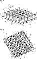
- Fig. 1 shows a perspective view of a structural body 1 according to the invention for use in a drainage system.
- the structural body 1 which has a square basic shape, comprises a square basic grid 3 surrounded by frame-like stabilizing side walls 2, from which 36 support elements 4 with an octagonal cross-section protrude, which taper towards the top like a truncated pyramid.
- the support elements 4 are hollow, cf. also Fig. 2 and Fig. 5 , and distributed homogeneously like a matrix in six rows of six carrying elements 4 each.
- the entire structural body 1 is an injection molded element made of plastic.
- the basic grid 3 has grid webs 5, at which the columnar support elements 4 are connected via rib-like extensions 6 at the points at which an outer wall of the octagonal support elements 4 runs parallel to a grid web 5.
- two structural bodies 1 can be connected to one another in opposite directions in order to define a receiving volume of a drainage system.
- the structural body 1 comprises connecting devices both on the carrying elements 4 and on the basic grid 3, which in the present case are designed as engagement cams 7, 8 and corresponding engagement receptacles 9, 10.
- the upper surfaces of the carrying elements 4 partially have three engagement receptacles 9 and an engagement cam 7, and in some cases only four engagement receptacles 9.
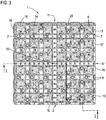
- Fig. 3 it is best that the areas of the basic grid 3 not occupied by the support elements 4, apart from the central rows 11, 12, have successive rows of engagement cams 8 and engagement receptacles 10, two engagement receptacles 10 always being located between two engagement cams 8.
- This respective arrangement of the engagement cams 7, 8 and the engagement receptacles 9, 10 is based on two axis symmetries, namely on the one hand an axis symmetry about the vertical central axis 13 (at the intersection of the rows 11, 12).
- This axisymmetry enables two structural bodies 1 to be placed on one another even when one of the structural bodies 1 has been rotated by 90 °. There is therefore a rotational symmetry when one of the two structural bodies 1 to be stacked in opposite directions is rotated by 90 °.
- This latter symmetry is based on the fact that it should be possible to cut the structural body 1 by cutting into substructure bodies which are identical with regard to the arrangement of the carrying elements and the engagement cams, for which purpose cut markings 15 are provided along the central rows 11, 12, which here as two parallel elevations or grooves are formed and can also serve as a cutting aid. If the structural body 1 is divided along these predetermined cutting lines, two halves or four quarters are formed which, owing to the symmetries described, can easily be stacked in opposite directions on one another in the vertical direction. In this way, half or quarter structural bodies can be produced which, in a infiltration system, enable the structural bodies 1 to be arranged in different positions and thus to provide greater stability.
- hooks 16 are formed on two sides of the structural body 1, hook receptacles corresponding to the hooks 17 on the other two sides of the structural body 1. By hooking the hooks 16 into the hook receptacles 17, horizontally adjacent structural bodies 1 can be connected.
- both the engagement cams 7, 8 can be positively inserted into the engagement receptacles 9, 10 and the hooks 16 can be positively inserted into the hook receptacles 17.
- It can also be a non-positive connection, for example by a clamp bracket, or it can be provided locking lugs or the like, which snap into corresponding locking receptacles in the hook receptacles 17 in order to achieve a firm, stable hold.
- the structural bodies 1 can be stacked in opposite directions on one another in use in a infiltration system, two structural bodies connected via the engagement cams 7 and the engagement receptacles 9 forming an infiltration unit, but of course further structural bodies are placed on the engagement cams 8 and the engagement receptacles 10 can.
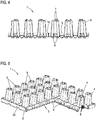
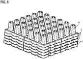
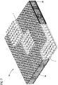
- the structural body 1 as by Fig. 6 shown, are nested in the same direction, with the inner hollow support elements 4 in this way into the support elements 4 of the one above Intervene structural body 1, that ultimately the basic grids 3 come to lie completely on top of one another and that maximum space is gained during transport and storage.
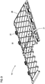
- Fig. 7 shows an example of a section from a drainage system 18 according to the invention. It can be seen that a plurality of structural bodies 1 are stacked on top of one another in opposite directions in order to form a drainage volume. On the outside, the trench volume can be closed off via side grille elements 19 which relate to the Fig. 8 and 9 are to be explained in more detail.
- the side grille element 19 has a central, higher grille 20 which is surrounded by a lower frame 21.
- the frame 21 has locking lugs 22, which in corresponding openings 23 (see. Fig. 1 . 3 and 5 ) engage and lock there if the side rail element 19 is to be attached to the structural bodies 1.
- the frame 21 rests on the basic grid 3 of the structural body 1, with locking lugs 22 engaging in the openings 23 and latching there via corresponding projections.
- the higher grating 20 engages to a certain extent in the area that is reset due to the carrying elements 4.
- the grid 20 also has cutting marks 24 in order to cut openings in the grid 20 which are suitable for an inflow or outflow. Furthermore, cutting marks 25 are provided in the center in order to cut the side rail element 19 into two halves 26 of the same size as they are in FIG Fig. 7 be used. In order to ensure the stability of the grid 20 even when the side grid element 19 is cut, the grid 20 comprises additional webs 27 on both sides of the desired cutting line.
- Fig. 7 shows, the divisibility of the structural body 1 and the side rail elements 19 enables an extremely flexible construction of the entire drainage system, which ensures increased stability after the structural body 1, as in the open part of FIG Fig. 7 can be seen, can be arranged offset to each other. A flush conclusion is nevertheless always possible after the structural bodies 1 are divisible or quarterable, as already described above.
- Fig. 10 shows the connection of horizontally adjacent structural bodies 1. As can be seen, the hooks 16 on one side of a structural body 1 engage in the openings 17 on another side of a further structural body 1.
- Fig. 11 now shows in detail the basic grid-side connection of two structural bodies 1 arranged in opposite directions.
- the basic grid-side engagement cams 8 each engage in a form-fitting manner in basic grid-side engagement receptacles 10.
- latching elements can also be provided for latching.
- Fig. 11 also shows again in detail how the support elements 4 are connected to the webs 5 of the basic grid 3 via ribs 6.
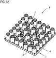
- Fig. 12 shows a structural body 1 'according to the invention in a second embodiment, which differs from the structural body 1 essentially in the shape and arrangement of the support elements 4 now realized as truncated cones.
- the support elements 4 are obviously arranged on the edge in a denser packing than in the interior of the structural body 1 '.
- the support elements 4 arranged in the middle can be provided homogeneously in less dense packing.
- FIG. 13 shows how the structural bodies 1 'can be stacked in the same direction for transport to save space.
- the present invention can also be implemented with other numbers of supporting elements, for example by means of a structural body having five rows of five supporting elements, in which, in particular, a separation takes place on the basis of provided cutting marks, in which case unevenly sized substructure bodies are obtained ,
Landscapes
- Health & Medical Sciences (AREA)
- Life Sciences & Earth Sciences (AREA)
- Engineering & Computer Science (AREA)
- Hydrology & Water Resources (AREA)
- Public Health (AREA)
- Water Supply & Treatment (AREA)
- Sewage (AREA)
- Snaps, Bayonet Connections, Set Pins, And Snap Rings (AREA)
- Road Paving Structures (AREA)
- Connection Of Plates (AREA)
Claims (6)
- Corps de structure (1, 1') servant à former un système de rigoles (18), qui présente une structure ouverte tridimensionnelle, dans lequel est prévu un réseau de base (3), duquel surgissent une multitude d'éléments porteurs (4) creux, se rétrécissant vers le haut de telle manière que plusieurs corps de structure (1, 1') peuvent être emboîtés par l'introduction côté fond des éléments porteurs (4) d'un corps de structure (1, 1') inférieur dans les éléments porteurs (4) du corps de structure (1, 1') supérieur, dans lequel la délimitation latérale du corps de structure (1, 1') est formée par au moins une partie des éléments porteurs (4) verticaux, dans lequel au moins un dispositif de liaison est prévu pour relier des corps de structure (1, 1') adjacents en le système de rigoles (18), dans lequel le dispositif de liaison est réalisé sous la forme de cames de prise et de logements de prise, lesquels sont prévus au niveau de la surface supérieure des éléments porteurs (4) ainsi qu'au niveau du réseau de base (3), qui permettent, lors de l'agencement adjacent de corps de structure (1, 1') dans une direction verticale dans le système de rigoles (18) tout comme lors de l'agencement mutuel des corps de structure (1, 1'), un assemblage par enfichage des corps de structure (1, 1'), dans lequel au moins une came de prise (7) et au moins un logement de prise (9) sont prévus au niveau d'une surface supérieure d'au moins un élément porteur (4) du corps de structure (1, 1'), dans lequel la came de prise (7) est réalisée pour venir en prise par complémentarité de forme avec un logement de prise (9) d'un corps de structure (1, 1') adjacent d'un système de rigoles (18), et/ou qu'au moins une came de prise (8) et au moins un logement de prise (10) sont prévus sur le côté, tourné vers l'extérieur, du réseau de base (3) dans des zones qui ne sont pas occupées par des éléments porteurs (4), dans lequel la came de prise (8) est réalisée pour venir en prise par complémentarité de forme avec un logement de prise (10) d'un corps de structure (1, 1') adjacent d'un système de rigoles (18), et dans lequel les cames de prise (7, 8) et les logements de prise (9, 10) sont disposés de manière symétrique axialement par rapport à un axe central (13) vertical du corps de structure (1, 1') de sorte qu'en cas de rotations quelconques d'un corps de structure (1, 1') de multiples entiers de 90° autour de l'axe central (13) vertical ou en cas d'un décalage latéral d'un multiple entier d'un espacement d'élément porteur par rapport au deuxième corps de structure (1, 1'), une prise des cames de prise avec les logements de prise correspondants est systématiquement rendue possible, et dans lequel les cames de prise (7, 8) et les logements de prise (9, 10) sont disposés en outre de manière symétrique axialement par rapport à un axe central (14) d'un quart du corps de structure (1, 1').
- Corps de structure (1, 1') selon la revendication 1, caractérisé en ce que les éléments porteurs (4) du corps de structure (1, 1') sont réalisés de telle manière que plusieurs corps de structure (1, 1') peuvent être emboîtés dans le même sens avec des réseaux de base (3) se raccordant les uns aux autres directement.
- Corps de structure (1, 1') selon la revendication 1 ou 2, caractérisé en ce que le corps de structure (1, 1') est élaboré de manière symétrique de telle manière qu'il peut être divisé dans le cas d'un découpage vertical au centre le long d'un marquage de découpe (15) en deux ou quatre corps de sous-structure de même type par rapport à la répartition des éléments porteurs (4).
- Système de rigoles (18) comprenant au moins deux corps de structure (1 ; 1') pouvant être disposés ou disposés de manière adjacente selon l'une quelconque des revendications 1 à 3, caractérisé en ce qu'en cas d'assemblage par enfichage mutuel des corps de structure (1, 1') pour former le système de rigoles (18), dans le cas de rotations quelconques d'un corps de structure (1, 1') de multiples entiers de 90° autour de l'axe médian (13) vertical ou dans le cas d'un décalage latéral d'un multiple entier d'un espacement d'élément porteur par rapport au deuxième corps d'appui (1, 1'), une prise des cames de prise avec les logements de prise correspondants est systématiquement rendue possible.
- Système de rigoles (18) selon la revendication 4, caractérisé en ce qu'au moins un élément de réseau latéral (19) installé ou à installer au niveau d'un bord extérieur du système de rigoles (18) est prévu, en particulier un élément de réseau latéral (19), lequel surmonte au moins deux corps de structure (1, 1') disposés l'un au-dessus de l'autre de manière verticale en tant qu'une unité de rigoles.
- Système de rigoles (18) selon la revendication 3 à 5, caractérisé en ce qu'un dispositif de liaison est prévu pour appliquer l'élément de réseau latéral (19) au niveau d'au moins un réseau de base (3) d'un corps de structure (1, 1'), sous la forme d'ergots d'enclenchement (22) prévus au niveau de l'élément de réseau latéral (19) et/ou au niveau du corps de structure (1, 1'), qui s'enclenchent dans des ouvertures (23) du corps d'appui (1, 1') et/ou de l'élément de réseau latéral (19).
Priority Applications (1)
| Application Number | Priority Date | Filing Date | Title |
|---|---|---|---|
| PL16182754T PL3165687T3 (pl) | 2010-12-07 | 2011-12-06 | Korpus strukturalny dla systemu elementów rozsączająco-retencyjnych i system elementów rozsączająco-retencyjnych |
Applications Claiming Priority (2)
| Application Number | Priority Date | Filing Date | Title |
|---|---|---|---|
| DE202010016295U DE202010016295U1 (de) | 2010-12-07 | 2010-12-07 | Strukturkörper für ein Rigolensystem und Rigolensystem |
| EP11192040.1A EP2463449B1 (fr) | 2010-12-07 | 2011-12-06 | Corps de structure pour un système de rigole et système de rigole |
Related Parent Applications (2)
| Application Number | Title | Priority Date | Filing Date |
|---|---|---|---|
| EP11192040.1A Division EP2463449B1 (fr) | 2010-12-07 | 2011-12-06 | Corps de structure pour un système de rigole et système de rigole |
| EP11192040.1A Division-Into EP2463449B1 (fr) | 2010-12-07 | 2011-12-06 | Corps de structure pour un système de rigole et système de rigole |
Publications (3)
| Publication Number | Publication Date |
|---|---|
| EP3165687A2 EP3165687A2 (fr) | 2017-05-10 |
| EP3165687A3 EP3165687A3 (fr) | 2017-06-21 |
| EP3165687B1 true EP3165687B1 (fr) | 2020-02-19 |
Family
ID=45315568
Family Applications (2)
| Application Number | Title | Priority Date | Filing Date |
|---|---|---|---|
| EP16182754.8A Active EP3165687B1 (fr) | 2010-12-07 | 2011-12-06 | Corps de structure pour un système de rigole et système de rigole |
| EP11192040.1A Active EP2463449B1 (fr) | 2010-12-07 | 2011-12-06 | Corps de structure pour un système de rigole et système de rigole |
Family Applications After (1)
| Application Number | Title | Priority Date | Filing Date |
|---|---|---|---|
| EP11192040.1A Active EP2463449B1 (fr) | 2010-12-07 | 2011-12-06 | Corps de structure pour un système de rigole et système de rigole |
Country Status (3)
| Country | Link |
|---|---|
| EP (2) | EP3165687B1 (fr) |
| DE (1) | DE202010016295U1 (fr) |
| PL (2) | PL3165687T3 (fr) |
Cited By (2)
| Publication number | Priority date | Publication date | Assignee | Title |
|---|---|---|---|---|
| US12286782B2 (en) | 2021-10-07 | 2025-04-29 | Advanced Drainage Systems, Inc. | Stormwater management crate assembly with tapered columns |
| US12371891B2 (en) | 2021-12-30 | 2025-07-29 | Advanced Drainage Systems, Inc. | Stormwater box with trusses |
Families Citing this family (21)
| Publication number | Priority date | Publication date | Assignee | Title |
|---|---|---|---|---|
| DE102011086016A1 (de) * | 2011-11-09 | 2013-05-16 | Fränkische Rohrwerke Gebr. Kirchner Gmbh & Co. Kg | Rigoleneinheit und aus derartigen Rigoleneinheiten gebildete Transporteinheit |
| JP5783916B2 (ja) * | 2012-01-11 | 2015-09-24 | 株式会社Ihiインフラシステム | 貯水空間形成ブロック |
| DE202013101338U1 (de) | 2013-03-27 | 2014-07-04 | Rehau Ag + Co | Rigolensystem |
| CN104294881A (zh) * | 2013-07-19 | 2015-01-21 | 北京泰宁科创雨水利用技术股份有限公司 | 用于搭建水池的模块组件及采用该模块组件搭建的水池 |
| FR3011855B1 (fr) * | 2013-10-16 | 2017-12-22 | Nidaplast-Honeycombs | Demi-module de stockage pour bassin de retention |
| CN104746631A (zh) * | 2015-01-26 | 2015-07-01 | 江阴市星宇塑胶有限公司 | 一种雨水收集储存用塑料组装模块 |
| DE202015105746U1 (de) | 2015-10-29 | 2017-01-31 | Rehau Ag + Co | Speicher für Wärmeenergie in modularer Bauweise |
| CN105625548A (zh) * | 2016-03-10 | 2016-06-01 | 江苏河马井股份有限公司 | 渗排板 |
| DE202016107113U1 (de) * | 2016-12-19 | 2018-03-21 | Rehau Ag + Co | Rigolenhalbelement |
| DE202016107114U1 (de) * | 2016-12-19 | 2018-03-21 | Rehau Ag + Co | Rigolenhalbelement |
| DE102017105002A1 (de) | 2017-03-09 | 2018-09-13 | ACO Severin Ahlmann GmbH & Co Kommanditgesellschaft | Rigoleneinheit, Rigolenkörper und Einsatzstück |
| DE102017105011A1 (de) * | 2017-03-09 | 2018-09-13 | ACO Severin Ahlmann GmbH & Co Kommanditgesellschaft | Rigolenkörper und Mittelplatte |
| NL1042809B1 (en) * | 2018-04-04 | 2019-10-10 | Wavin Bv | Drainage system for connection to an infiltration system |
| NL2021404B1 (en) | 2018-07-27 | 2020-01-31 | Wavin Bv | A system and a method for building a road |
| WO2020041829A1 (fr) * | 2018-08-28 | 2020-03-05 | Elmich Pte Ltd | Structure de support |
| US20200248442A1 (en) * | 2019-02-06 | 2020-08-06 | Tensho Electric Industries Co.,Ltd. | Rainwater storage and infiltration facility |
| US20230243142A1 (en) * | 2021-10-07 | 2023-08-03 | Advanced Drainage Systems, Inc. | Stormwater management crate assembly with tapered columns and side panels with column bearing components |
| DE202021106956U1 (de) * | 2021-12-21 | 2023-03-22 | REHAU Industries SE & Co. KG | Rigolenanordnung |
| DE202021106944U1 (de) * | 2021-12-21 | 2023-03-23 | REHAU Industries SE & Co. KG | Rigolenanordnung |
| DE202021106945U1 (de) * | 2021-12-21 | 2023-03-22 | REHAU Industries SE & Co. KG | Rigolenanordnung |
| PL448178A1 (pl) | 2024-03-30 | 2025-10-06 | Kaczmarek Malewo Spółka Komandytowa | Skrzyniowy zestaw retencyjno-rozsączający z tworzywa sztucznego |
Family Cites Families (14)
| Publication number | Priority date | Publication date | Assignee | Title |
|---|---|---|---|---|
| US201848A (en) | 1878-03-26 | Improvement in preserving green coffee | ||
| GB2258792B (en) * | 1991-06-04 | 1996-03-13 | Alan Bamforth | Improvements in or relating to drainage elements or the like and meth od of manufacturing same |
| DE29924050U1 (de) * | 1998-03-18 | 2001-10-25 | Wavin B.V., Zwolle | Bewässerungs- und/oder Drainagekasten |
| US6428870B1 (en) * | 2000-12-26 | 2002-08-06 | William W. Bohnhoff | Subsurface fluid drainage and storage system and mat especially utilized for such system |
| GB2417733B (en) * | 2004-09-03 | 2008-01-30 | Marley Extrusions | Water drainage system |
| DE202005010090U1 (de) * | 2005-06-24 | 2005-09-22 | Hauraton Betonwarenfabrik Gmbh & Co Kg | Rigolenelement |
| FR2888591B1 (fr) * | 2005-07-13 | 2009-01-16 | Sogemap Injection Sa | Cellule et systeme de recuperation d'eau |
| US20080124175A1 (en) * | 2006-05-09 | 2008-05-29 | Darrell Riste | Water extraction panels system |
| JP5153238B2 (ja) * | 2007-07-09 | 2013-02-27 | 岐阜プラスチック工業株式会社 | 水貯留槽用の構造部材 |
| FR2929630B1 (fr) | 2008-04-02 | 2011-11-25 | Aliaxis Participations | Bac de retention d'eau permettant de constituer par assemblage de bacs un dispositif de retention d'eau enfoui dans le sol |
| CA2724556A1 (fr) * | 2008-05-16 | 2009-11-19 | Alan Sian Ghee Lee | Cellule de drainage flexible |
| US7815395B1 (en) * | 2009-04-08 | 2010-10-19 | Airfield Systems, L.L.C | Subsurface drainage system and drain structure therefor |
| JP4444366B1 (ja) * | 2009-07-08 | 2010-03-31 | 古河電気工業株式会社 | 水貯留施設、水貯留施設の施工方法、水貯留施設の水平方向耐荷重向上方法および骨格ブロックの水平方向ずれ防止方法 |
| DE102009044412A1 (de) * | 2009-10-05 | 2011-04-07 | Aco Severin Ahlmann Gmbh & Co. Kg | Rigolenkörper |
-
2010
- 2010-12-07 DE DE202010016295U patent/DE202010016295U1/de not_active Expired - Lifetime
-
2011
- 2011-12-06 EP EP16182754.8A patent/EP3165687B1/fr active Active
- 2011-12-06 PL PL16182754T patent/PL3165687T3/pl unknown
- 2011-12-06 PL PL11192040T patent/PL2463449T3/pl unknown
- 2011-12-06 EP EP11192040.1A patent/EP2463449B1/fr active Active
Non-Patent Citations (1)
| Title |
|---|
| None * |
Cited By (2)
| Publication number | Priority date | Publication date | Assignee | Title |
|---|---|---|---|---|
| US12286782B2 (en) | 2021-10-07 | 2025-04-29 | Advanced Drainage Systems, Inc. | Stormwater management crate assembly with tapered columns |
| US12371891B2 (en) | 2021-12-30 | 2025-07-29 | Advanced Drainage Systems, Inc. | Stormwater box with trusses |
Also Published As
| Publication number | Publication date |
|---|---|
| DE202010016295U1 (de) | 2012-03-12 |
| PL2463449T3 (pl) | 2019-09-30 |
| EP2463449B1 (fr) | 2019-03-06 |
| EP3165687A3 (fr) | 2017-06-21 |
| PL3165687T3 (pl) | 2020-08-10 |
| EP2463449A1 (fr) | 2012-06-13 |
| EP3165687A2 (fr) | 2017-05-10 |
Similar Documents
| Publication | Publication Date | Title |
|---|---|---|
| EP3165687B1 (fr) | Corps de structure pour un système de rigole et système de rigole | |
| EP2592194B1 (fr) | Unité de rigole et unité de transport formée à partir d'unités de rigole de ce type | |
| EP2470722B1 (fr) | Corps à rigoles | |
| DE60114178T2 (de) | Strukturelle modulare verbindbare bodendrainagezelle | |
| WO2016015786A1 (fr) | Élément de bloc de drainage, bloc de drainage et unité de transport | |
| EP2291070B1 (fr) | Pot pour plantes | |
| EP2325404A1 (fr) | Dispositif de stockage des fluids sous-terrain | |
| EP2495373A2 (fr) | Système de drainage, son procédé de fabrication et composants associés | |
| EP0371917A1 (fr) | Cadre de couronnement pour canal de drainage | |
| WO2010081681A2 (fr) | Système de rigoles comprenant au moins une boîte d'infiltration | |
| EP2379817B1 (fr) | Dispositif d'infiltration avec plusieurs boîtes d'infiltration comprenant un logement pour un élément de stabilisation | |
| DE10045814C1 (de) | Gitterplatte | |
| EP2492400A1 (fr) | Corps d'encastrement | |
| DE102007036005A1 (de) | Bodenbefestigungsplatte | |
| EP3626646B1 (fr) | Boîte empilable | |
| WO2018083346A1 (fr) | Dispositif servant à former des cavités praticables ménagées dans le sol à des fins de drainage et/ou de stockage d'eau | |
| EP2148016B1 (fr) | Agencement de rigoles | |
| EP3443169A1 (fr) | Dispositif de formation de cavités dans le sol à des fins de drainage et/ou de stockage de l'eau | |
| DE102004025335B4 (de) | Einbauelement und dessen Verwendung zum Einbau in einen Hohlraum | |
| WO2025224199A1 (fr) | Dispositif de contenant pouvant être fixé et son utilisation | |
| EP4453336A1 (fr) | Système de transport constitué d'un ensemble rigole | |
| EP1643606A1 (fr) | Chambre à câbles | |
| DE102024127854A1 (de) | Aufsatzbehältervorrichtung und deren Verwendung | |
| DE202019100340U1 (de) | Vorrichtung zur Bildung von Hohlräumen im Erdreich zu Entwässerungs- und/oder Wasserspeicherungszwecken | |
| DE7907270U1 (de) | Hohlblock-bauelement |
Legal Events
| Date | Code | Title | Description |
|---|---|---|---|
| PUAI | Public reference made under article 153(3) epc to a published international application that has entered the european phase |
Free format text: ORIGINAL CODE: 0009012 |
|
| STAA | Information on the status of an ep patent application or granted ep patent |
Free format text: STATUS: THE APPLICATION HAS BEEN PUBLISHED |
|
| AC | Divisional application: reference to earlier application |
Ref document number: 2463449 Country of ref document: EP Kind code of ref document: P |
|
| AK | Designated contracting states |
Kind code of ref document: A2 Designated state(s): AL AT BE BG CH CY CZ DE DK EE ES FI FR GB GR HR HU IE IS IT LI LT LU LV MC MK MT NL NO PL PT RO RS SE SI SK SM TR |
|
| PUAL | Search report despatched |
Free format text: ORIGINAL CODE: 0009013 |
|
| AK | Designated contracting states |
Kind code of ref document: A3 Designated state(s): AL AT BE BG CH CY CZ DE DK EE ES FI FR GB GR HR HU IE IS IT LI LT LU LV MC MK MT NL NO PL PT RO RS SE SI SK SM TR |
|
| RIC1 | Information provided on ipc code assigned before grant |
Ipc: E03F 1/00 20060101AFI20170518BHEP |
|
| STAA | Information on the status of an ep patent application or granted ep patent |
Free format text: STATUS: REQUEST FOR EXAMINATION WAS MADE |
|
| 17P | Request for examination filed |
Effective date: 20171220 |
|
| RBV | Designated contracting states (corrected) |
Designated state(s): AL AT BE BG CH CY CZ DE DK EE ES FI FR GB GR HR HU IE IS IT LI LT LU LV MC MK MT NL NO PL PT RO RS SE SI SK SM TR |
|
| GRAP | Despatch of communication of intention to grant a patent |
Free format text: ORIGINAL CODE: EPIDOSNIGR1 |
|
| STAA | Information on the status of an ep patent application or granted ep patent |
Free format text: STATUS: GRANT OF PATENT IS INTENDED |
|
| INTG | Intention to grant announced |
Effective date: 20190830 |
|
| GRAS | Grant fee paid |
Free format text: ORIGINAL CODE: EPIDOSNIGR3 |
|
| GRAA | (expected) grant |
Free format text: ORIGINAL CODE: 0009210 |
|
| STAA | Information on the status of an ep patent application or granted ep patent |
Free format text: STATUS: THE PATENT HAS BEEN GRANTED |
|
| RAP1 | Party data changed (applicant data changed or rights of an application transferred) |
Owner name: REHAU SAS Owner name: REHAU AG + CO |
|
| AC | Divisional application: reference to earlier application |
Ref document number: 2463449 Country of ref document: EP Kind code of ref document: P |
|
| AK | Designated contracting states |
Kind code of ref document: B1 Designated state(s): AL AT BE BG CH CY CZ DE DK EE ES FI FR GB GR HR HU IE IS IT LI LT LU LV MC MK MT NL NO PL PT RO RS SE SI SK SM TR |
|
| REG | Reference to a national code |
Ref country code: CH Ref legal event code: EP |
|
| REG | Reference to a national code |
Ref country code: DE Ref legal event code: R096 Ref document number: 502011016481 Country of ref document: DE |
|
| REG | Reference to a national code |
Ref country code: AT Ref legal event code: REF Ref document number: 1235109 Country of ref document: AT Kind code of ref document: T Effective date: 20200315 |
|
| REG | Reference to a national code |
Ref country code: IE Ref legal event code: FG4D Free format text: LANGUAGE OF EP DOCUMENT: GERMAN |
|
| REG | Reference to a national code |
Ref country code: NL Ref legal event code: FP |
|
| PG25 | Lapsed in a contracting state [announced via postgrant information from national office to epo] |
Ref country code: NO Free format text: LAPSE BECAUSE OF FAILURE TO SUBMIT A TRANSLATION OF THE DESCRIPTION OR TO PAY THE FEE WITHIN THE PRESCRIBED TIME-LIMIT Effective date: 20200519 Ref country code: RS Free format text: LAPSE BECAUSE OF FAILURE TO SUBMIT A TRANSLATION OF THE DESCRIPTION OR TO PAY THE FEE WITHIN THE PRESCRIBED TIME-LIMIT Effective date: 20200219 Ref country code: FI Free format text: LAPSE BECAUSE OF FAILURE TO SUBMIT A TRANSLATION OF THE DESCRIPTION OR TO PAY THE FEE WITHIN THE PRESCRIBED TIME-LIMIT Effective date: 20200219 |
|
| REG | Reference to a national code |
Ref country code: LT Ref legal event code: MG4D |
|
| PG25 | Lapsed in a contracting state [announced via postgrant information from national office to epo] |
Ref country code: HR Free format text: LAPSE BECAUSE OF FAILURE TO SUBMIT A TRANSLATION OF THE DESCRIPTION OR TO PAY THE FEE WITHIN THE PRESCRIBED TIME-LIMIT Effective date: 20200219 Ref country code: LV Free format text: LAPSE BECAUSE OF FAILURE TO SUBMIT A TRANSLATION OF THE DESCRIPTION OR TO PAY THE FEE WITHIN THE PRESCRIBED TIME-LIMIT Effective date: 20200219 Ref country code: SE Free format text: LAPSE BECAUSE OF FAILURE TO SUBMIT A TRANSLATION OF THE DESCRIPTION OR TO PAY THE FEE WITHIN THE PRESCRIBED TIME-LIMIT Effective date: 20200219 Ref country code: IS Free format text: LAPSE BECAUSE OF FAILURE TO SUBMIT A TRANSLATION OF THE DESCRIPTION OR TO PAY THE FEE WITHIN THE PRESCRIBED TIME-LIMIT Effective date: 20200619 Ref country code: BG Free format text: LAPSE BECAUSE OF FAILURE TO SUBMIT A TRANSLATION OF THE DESCRIPTION OR TO PAY THE FEE WITHIN THE PRESCRIBED TIME-LIMIT Effective date: 20200519 Ref country code: GR Free format text: LAPSE BECAUSE OF FAILURE TO SUBMIT A TRANSLATION OF THE DESCRIPTION OR TO PAY THE FEE WITHIN THE PRESCRIBED TIME-LIMIT Effective date: 20200520 |
|
| PG25 | Lapsed in a contracting state [announced via postgrant information from national office to epo] |
Ref country code: CZ Free format text: LAPSE BECAUSE OF FAILURE TO SUBMIT A TRANSLATION OF THE DESCRIPTION OR TO PAY THE FEE WITHIN THE PRESCRIBED TIME-LIMIT Effective date: 20200219 Ref country code: ES Free format text: LAPSE BECAUSE OF FAILURE TO SUBMIT A TRANSLATION OF THE DESCRIPTION OR TO PAY THE FEE WITHIN THE PRESCRIBED TIME-LIMIT Effective date: 20200219 Ref country code: SK Free format text: LAPSE BECAUSE OF FAILURE TO SUBMIT A TRANSLATION OF THE DESCRIPTION OR TO PAY THE FEE WITHIN THE PRESCRIBED TIME-LIMIT Effective date: 20200219 Ref country code: PT Free format text: LAPSE BECAUSE OF FAILURE TO SUBMIT A TRANSLATION OF THE DESCRIPTION OR TO PAY THE FEE WITHIN THE PRESCRIBED TIME-LIMIT Effective date: 20200712 Ref country code: LT Free format text: LAPSE BECAUSE OF FAILURE TO SUBMIT A TRANSLATION OF THE DESCRIPTION OR TO PAY THE FEE WITHIN THE PRESCRIBED TIME-LIMIT Effective date: 20200219 Ref country code: EE Free format text: LAPSE BECAUSE OF FAILURE TO SUBMIT A TRANSLATION OF THE DESCRIPTION OR TO PAY THE FEE WITHIN THE PRESCRIBED TIME-LIMIT Effective date: 20200219 Ref country code: SM Free format text: LAPSE BECAUSE OF FAILURE TO SUBMIT A TRANSLATION OF THE DESCRIPTION OR TO PAY THE FEE WITHIN THE PRESCRIBED TIME-LIMIT Effective date: 20200219 Ref country code: DK Free format text: LAPSE BECAUSE OF FAILURE TO SUBMIT A TRANSLATION OF THE DESCRIPTION OR TO PAY THE FEE WITHIN THE PRESCRIBED TIME-LIMIT Effective date: 20200219 Ref country code: RO Free format text: LAPSE BECAUSE OF FAILURE TO SUBMIT A TRANSLATION OF THE DESCRIPTION OR TO PAY THE FEE WITHIN THE PRESCRIBED TIME-LIMIT Effective date: 20200219 |
|
| REG | Reference to a national code |
Ref country code: DE Ref legal event code: R097 Ref document number: 502011016481 Country of ref document: DE |
|
| RAP2 | Party data changed (patent owner data changed or rights of a patent transferred) |
Owner name: REHAU AG + CO Owner name: REHAU SAS |
|
| PLBE | No opposition filed within time limit |
Free format text: ORIGINAL CODE: 0009261 |
|
| STAA | Information on the status of an ep patent application or granted ep patent |
Free format text: STATUS: NO OPPOSITION FILED WITHIN TIME LIMIT |
|
| 26N | No opposition filed |
Effective date: 20201120 |
|
| PG25 | Lapsed in a contracting state [announced via postgrant information from national office to epo] |
Ref country code: SI Free format text: LAPSE BECAUSE OF FAILURE TO SUBMIT A TRANSLATION OF THE DESCRIPTION OR TO PAY THE FEE WITHIN THE PRESCRIBED TIME-LIMIT Effective date: 20200219 |
|
| PG25 | Lapsed in a contracting state [announced via postgrant information from national office to epo] |
Ref country code: MC Free format text: LAPSE BECAUSE OF FAILURE TO SUBMIT A TRANSLATION OF THE DESCRIPTION OR TO PAY THE FEE WITHIN THE PRESCRIBED TIME-LIMIT Effective date: 20200219 |
|
| PG25 | Lapsed in a contracting state [announced via postgrant information from national office to epo] |
Ref country code: IE Free format text: LAPSE BECAUSE OF NON-PAYMENT OF DUE FEES Effective date: 20201206 |
|
| REG | Reference to a national code |
Ref country code: DE Ref legal event code: R081 Ref document number: 502011016481 Country of ref document: DE Owner name: REHAU S.A., FR Free format text: FORMER OWNERS: REHAU AG + CO, 95111 REHAU, DE; REHAU SAS, MORHANGE, FR Ref country code: DE Ref legal event code: R081 Ref document number: 502011016481 Country of ref document: DE Owner name: REHAU INDUSTRIES SE & CO. KG, DE Free format text: FORMER OWNERS: REHAU AG + CO, 95111 REHAU, DE; REHAU SAS, MORHANGE, FR |
|
| REG | Reference to a national code |
Ref country code: LU Ref legal event code: PD Owner name: REHAU SAS; FR Free format text: FORMER OWNER: REHAU AG + CO Effective date: 20220329 |
|
| REG | Reference to a national code |
Ref country code: NL Ref legal event code: PD Owner name: REHAU SAS; FR Free format text: DETAILS ASSIGNMENT: CHANGE OF OWNER(S), ASSIGNMENT; FORMER OWNER NAME: REHAU SAS Effective date: 20220425 Ref country code: NL Ref legal event code: HC Owner name: REHAU SAS; FR Free format text: DETAILS ASSIGNMENT: CHANGE OF OWNER(S), CHANGE OF OWNER(S) NAME; FORMER OWNER NAME: REHAU SAS Effective date: 20220425 |
|
| PG25 | Lapsed in a contracting state [announced via postgrant information from national office to epo] |
Ref country code: TR Free format text: LAPSE BECAUSE OF FAILURE TO SUBMIT A TRANSLATION OF THE DESCRIPTION OR TO PAY THE FEE WITHIN THE PRESCRIBED TIME-LIMIT Effective date: 20200219 Ref country code: MT Free format text: LAPSE BECAUSE OF FAILURE TO SUBMIT A TRANSLATION OF THE DESCRIPTION OR TO PAY THE FEE WITHIN THE PRESCRIBED TIME-LIMIT Effective date: 20200219 Ref country code: CY Free format text: LAPSE BECAUSE OF FAILURE TO SUBMIT A TRANSLATION OF THE DESCRIPTION OR TO PAY THE FEE WITHIN THE PRESCRIBED TIME-LIMIT Effective date: 20200219 |
|
| REG | Reference to a national code |
Ref country code: AT Ref legal event code: PC Ref document number: 1235109 Country of ref document: AT Kind code of ref document: T Owner name: REHAU SAS, FR Effective date: 20220419 Ref country code: AT Ref legal event code: PC Ref document number: 1235109 Country of ref document: AT Kind code of ref document: T Owner name: REHAU INDUSTRIES SE & CO. KG, DE Effective date: 20220419 |
|
| REG | Reference to a national code |
Ref country code: GB Ref legal event code: 732E Free format text: REGISTERED BETWEEN 20220526 AND 20220601 |
|
| REG | Reference to a national code |
Ref country code: BE Ref legal event code: PD Owner name: REHAU SAS; FR Free format text: DETAILS ASSIGNMENT: CHANGE OF OWNER(S), OTHER; FORMER OWNER NAME: REHAU AG + CO Effective date: 20220414 Ref country code: BE Ref legal event code: PD Owner name: REHAU SAS; FR Free format text: DETAILS ASSIGNMENT: CHANGE OF OWNER(S), OTHER; FORMER OWNER NAME: REHAU SAS Effective date: 20220414 |
|
| PG25 | Lapsed in a contracting state [announced via postgrant information from national office to epo] |
Ref country code: MK Free format text: LAPSE BECAUSE OF FAILURE TO SUBMIT A TRANSLATION OF THE DESCRIPTION OR TO PAY THE FEE WITHIN THE PRESCRIBED TIME-LIMIT Effective date: 20200219 Ref country code: AL Free format text: LAPSE BECAUSE OF FAILURE TO SUBMIT A TRANSLATION OF THE DESCRIPTION OR TO PAY THE FEE WITHIN THE PRESCRIBED TIME-LIMIT Effective date: 20200219 |
|
| REG | Reference to a national code |
Ref country code: LU Ref legal event code: HC Owner name: REHAU SAS; FR Free format text: FORMER OWNER: REHAU INDUSTRIES SE & CO. KG Effective date: 20230828 |
|
| PGFP | Annual fee paid to national office [announced via postgrant information from national office to epo] |
Ref country code: CH Payment date: 20250101 Year of fee payment: 14 |
|
| PGFP | Annual fee paid to national office [announced via postgrant information from national office to epo] |
Ref country code: PL Payment date: 20250916 Year of fee payment: 15 |
|
| PGFP | Annual fee paid to national office [announced via postgrant information from national office to epo] |
Ref country code: NL Payment date: 20251120 Year of fee payment: 15 |
|
| REG | Reference to a national code |
Ref country code: CH Ref legal event code: U11 Free format text: ST27 STATUS EVENT CODE: U-0-0-U10-U11 (AS PROVIDED BY THE NATIONAL OFFICE) Effective date: 20260101 |
|
| PGFP | Annual fee paid to national office [announced via postgrant information from national office to epo] |
Ref country code: GB Payment date: 20251111 Year of fee payment: 15 |
|
| PGFP | Annual fee paid to national office [announced via postgrant information from national office to epo] |
Ref country code: AT Payment date: 20251120 Year of fee payment: 15 |
|
| PGFP | Annual fee paid to national office [announced via postgrant information from national office to epo] |
Ref country code: IT Payment date: 20251230 Year of fee payment: 15 |
|
| PGFP | Annual fee paid to national office [announced via postgrant information from national office to epo] |
Ref country code: FR Payment date: 20251125 Year of fee payment: 15 Ref country code: LU Payment date: 20251119 Year of fee payment: 15 |
|
| PGFP | Annual fee paid to national office [announced via postgrant information from national office to epo] |
Ref country code: BE Payment date: 20251120 Year of fee payment: 15 |
|
| PGFP | Annual fee paid to national office [announced via postgrant information from national office to epo] |
Ref country code: DE Payment date: 20251231 Year of fee payment: 15 |