EP3165692A1 - Dispositif sectionnel de protection contre les intempéries - Google Patents
Dispositif sectionnel de protection contre les intempéries Download PDFInfo
- Publication number
- EP3165692A1 EP3165692A1 EP16197246.8A EP16197246A EP3165692A1 EP 3165692 A1 EP3165692 A1 EP 3165692A1 EP 16197246 A EP16197246 A EP 16197246A EP 3165692 A1 EP3165692 A1 EP 3165692A1
- Authority
- EP
- European Patent Office
- Prior art keywords
- protection device
- weather protection
- section
- sectional
- vehicle
- Prior art date
- Legal status (The legal status is an assumption and is not a legal conclusion. Google has not performed a legal analysis and makes no representation as to the accuracy of the status listed.)
- Withdrawn
Links
- 230000033001 locomotion Effects 0.000 claims abstract description 42
- 239000000463 material Substances 0.000 description 5
- 238000011161 development Methods 0.000 description 4
- 230000018109 developmental process Effects 0.000 description 4
- 238000007789 sealing Methods 0.000 description 4
- 244000007853 Sarothamnus scoparius Species 0.000 description 2
- 229910000831 Steel Inorganic materials 0.000 description 2
- XAGFODPZIPBFFR-UHFFFAOYSA-N aluminium Chemical compound [Al] XAGFODPZIPBFFR-UHFFFAOYSA-N 0.000 description 2
- 229910052782 aluminium Inorganic materials 0.000 description 2
- 238000004873 anchoring Methods 0.000 description 2
- 230000000694 effects Effects 0.000 description 2
- 230000003993 interaction Effects 0.000 description 2
- 238000005096 rolling process Methods 0.000 description 2
- 239000007787 solid Substances 0.000 description 2
- 239000010959 steel Substances 0.000 description 2
- 229920005372 Plexiglas® Polymers 0.000 description 1
- 238000010276 construction Methods 0.000 description 1
- 230000001419 dependent effect Effects 0.000 description 1
- 230000009977 dual effect Effects 0.000 description 1
- 239000006260 foam Substances 0.000 description 1
- 238000007373 indentation Methods 0.000 description 1
- 238000009413 insulation Methods 0.000 description 1
- 210000003205 muscle Anatomy 0.000 description 1
- 239000004926 polymethyl methacrylate Substances 0.000 description 1
- 230000001681 protective effect Effects 0.000 description 1
- 230000002787 reinforcement Effects 0.000 description 1
- 230000000284 resting effect Effects 0.000 description 1
- 230000002277 temperature effect Effects 0.000 description 1
- 239000010875 treated wood Substances 0.000 description 1
Images







Classifications
-
- E—FIXED CONSTRUCTIONS
- E04—BUILDING
- E04H—BUILDINGS OR LIKE STRUCTURES FOR PARTICULAR PURPOSES; SWIMMING OR SPLASH BATHS OR POOLS; MASTS; FENCING; TENTS OR CANOPIES, IN GENERAL
- E04H6/00—Buildings for parking cars, rolling-stock, aircraft, vessels or like vehicles, e.g. garages
- E04H6/02—Small garages, e.g. for one or two cars
- E04H6/04—Small garages, e.g. for one or two cars wheeled, hinged, foldable, telescopic, swinging or otherwise movable
-
- E—FIXED CONSTRUCTIONS
- E04—BUILDING
- E04B—GENERAL BUILDING CONSTRUCTIONS; WALLS, e.g. PARTITIONS; ROOFS; FLOORS; CEILINGS; INSULATION OR OTHER PROTECTION OF BUILDINGS
- E04B1/00—Constructions in general; Structures which are not restricted either to walls, e.g. partitions, or floors or ceilings or roofs
- E04B1/343—Structures characterised by movable, separable, or collapsible parts, e.g. for transport
- E04B1/34305—Structures characterised by movable, separable, or collapsible parts, e.g. for transport telescopic
Definitions
- the invention relates to a sectional weather protection device, comprising a trunk section which at least partially surrounds an interior space laterally and above, and which has a first floor support element and a second floor support element, and at least one first mobile section which is moveable to the trunk section at the first and the second Floor support element is arranged to be moved between a first, open position and a second, closed position can.
- the invention further relates to a use of a sectional weather protection device as a garage.
- Sectional weather protection devices are known from the prior art. They consist of several sections, which are arranged displaceably to each other and serve in particular the protection of objects disposed therein, such as dumpsters, against external weather influences such as rain or snow.
- these sectional weather protection devices are designed either purely mobile, so that they can be moved at any time, including objects arranged therein, or anchored in the ground that they require a complex foundation, whereby the access to the object arranged therein is difficult.
- US4288949A describes a modular garage for vehicles, comprising two mutually telekopierbare housing elements.
- the garage is secured by anchored in the ground pins and a lid-side locking.
- a disadvantage of this design is the lack of security of the device against burglary, since these security measures do not ensure sufficient security against prying or leveraging.
- JP2002-4615A describes a telescopic garage, in which the telescopic housing unit is anchored to rails and this encompasses. Again, an anti-theft device is dependent on a complex anchoring of the rails on the ground, the nature of the ground and execution of this anchorage.
- FR2921400A1 shows a telescopic garage for two-wheelers. Also, this garage has the disadvantage that a backup of the garage is generally guaranteed insufficient, since the telescopic housing unit does not provide sufficient security against prying or leveraging.
- Out JP 2015-143412 A is a similar storage device for two-wheelers known.
- a disadvantage of these weather protection devices is mobility on the one hand, which makes protection of valuable items in the protection device against unauthorized access impossible.
- a foundation and ground anchoring is disadvantageous because it is associated with considerable effort.
- a sectional weather protection device of the type described in the introduction in which at least one first load-receiving device is fastened to the ground support elements, the load-receiving device being formed, to secure the weather protection device against movement by loading the weight of an object arranged in the weather protection device.
- a length is meant in the sense of this description and claims an extension or direction which is substantially parallel to the plane of the ground.
- a width is meant an extent or direction that is substantially parallel to the plane of the ground, and substantially perpendicular to the length.
- a height is meant an extent or direction that is substantially perpendicular to the plane of the ground and also perpendicular to the length and perpendicular to the width and thus spans a three-dimensional coordinate system.
- the trunk section which may also be referred to as a main or basic section, has a height, a width and a depth and encloses an interior laterally and above at least partially. In this interior, the object to be protected is preferably arranged.
- the trunk section further includes two bottom support members that preferably extend along the length of the interior and beyond the interior.
- the ground support elements are arranged on the ground and preferably have the same length.
- the ground support elements preferably run parallel to one another and are spaced from one another, preferably by a width of the weather protection device.
- the length of the ground support elements preferably corresponds to the length of the weather protection device and / or defines it.
- the length of the ground support elements substantially corresponds to the length of the object to be arranged in the weather protection device.
- the height of the ground support elements is flat, preferably not higher than 10 cm, more preferably not higher than 5 cm.
- the ground support elements are preferably made of a weather-resistant and solid, preferably rigid material, for example steel.
- the bottom support elements have a sealing element on the underside, for sealing against the ground on which the weather protection device is arranged, and in particular to compensate for unevenness of the ground.
- This sealing element is formed for example of a flexible material, preferably made of rubber.
- the mobile section is movably arranged to the trunk section on the ground support members so that it can be moved back and forth between an open and a closed position.
- the mobile section is arranged in the open position closer to the interior of the trunk section than in the closed position.
- the movement is preferably linear, along the length of the ground support elements and is, for example, a sliding and / or rubbing movement of the underside of the mobile section on the ground support elements.
- the mobile section is configured and arranged such that it can be moved solely by muscle power.
- the mobile section can also be provided with a drive which can support or completely take over the movement in relation to the interior of the trunk section.
- the mobile section may be at least partially disposed in the open position about or above the trunk section.
- the sectional weather protection device may also have more than one mobile section, for example two, three or more. A second mobile section is then located in the closed position farther away from the interior of the trunk section than the first mobile section and a third mobile section farther away from the interior of the trunk section than the second mobile section.
- the sectional weather protection device preferably has a number of mobile sections and / or length of the mobile sections adapted to the length of the object or objects to be arranged in the weather protection device.
- the length of the stem section and / or the mobile section (s) is not more than 5.00m, preferably not more than 3.00m, more preferably not more than 2.50m, more preferably not more than 2.20m.
- the overall length of the weather protection device is typically not more than 15m, preferably not more than 10m, more preferably not more than 6m
- At least one first load handling device is attached to the ground support elements.
- This load receiving device is in particular flat, preferably as a plate with an upper bearing surface, formed and secured to the ground support elements that it ensures the weather protection device according to the invention by loading the weight of an arranged in the weather protection device and on the load-receiving device object against movement. By positioning an object to be protected on the load-carrying device, the load-receiving device takes on its weight. This weight is transmitted to the ground support members by the load handling device. For this purpose, load-carrying device and ground support element for transmitting this weight are coupled. The weight thus acts on the entire weather protection device and thus protects them against movement, preferably in all directions.
- the load handling device is preferably releasably attached to the ground support elements, for example by a latching or plugging mechanism which prevents movement of the ground support elements upwardly away from the ground and laterally in a plane parallel to the ground, along the length of the ground support elements, e.g. so-called dovetail profile on the ground support elements and the load bearing device.
- the load-receiving device is formed of a stiff, in particular torsionally rigid material, for example steel.
- the construction according to the invention has the advantage that, apart from the object arranged in the weather protection device, no further securing measures are necessary to secure the weather protection device against movement.
- the invention can be further developed in that a second load-bearing device is attached to the ground support elements, wherein preferably the first load-bearing device has a brake wedge.
- the load receiving devices are mounted between the ground support elements.
- both load receiving devices along the length of the ground support elements are spaced from each other and attached to both sides of the ground support elements, preferably releasably secured.
- the first load-bearing device is arranged within the interior of the trunk section and the second load-bearing device is arranged within the interior of the mobile section. It is also possible for more than two load-carrying devices to be arranged on the ground support elements, for example four. In this case, preferably two load receiving devices spaced along the length of the ground support elements to each other on the one ground support element arranged and arranged two further load receiving device with a substantially equal spacing, the first two load receiving devices on the second ground support element.
- the first load receiving device preferably has a brake wedge.
- This brake wedge is preferably arranged on the surface of the first load receiving device and in cross section in side view conical, triangular or quarter-circle-shaped, so that a wheel is locked or blocked in a predetermined position by the brake wedge.
- the brake wedge is closer to a ground support element arranged as to the other ground support element.
- the brake wedge is preferably at least 10 cm wide, more preferably at least 15 cm, even more preferably at least 20 cm wide.
- the brake wedge may also be arranged over the entire width of the first load-receiving device or it may be arranged on the first load-receiving device, two brake wedges.
- the brake wedge according to the invention has the task of securing an object arranged in the weather protection device, in particular a vehicle, against undesired movement within the weather protection device. He has further the task of acting as a stop when driving a vehicle into the weather protection device to prevent accidental bumping of the vehicle to a rear wall of the trunk section.
- This solution has the advantage that a vehicle can be introduced without instruction or distance control to the brake wedge to the desired position on the load-receiving device, and then stand at a small distance to the rear wall.
- the first load-receiving device and / or the second load-receiving device is detachably arranged on the ground support elements such that their position along the length of the ground support elements can be varied.
- each load receiving device can be varied in its position individually, but at least the distance between the two load receiving devices to each other along the length of the ground support elements.
- the trunk section has at least one roof element and a rear wall.
- the roof element may be formed as a flat roof and extends parallel or slightly inclined to the ground plane. It is in this case preferably formed at right angles to the rear wall and preferably has a substantially rectangular roof surface.
- the roof element may be formed as a round roof or pitched roof.
- the roof element may preferably extend to the ground, so that wall elements can be dispensed with.
- the roof element is flat, but slightly angled with respect to the plane of the ground in one direction along the length of the ground support elements.
- the angle is preferably less than 20 °, more preferably less than 15 °, particularly preferably less than 10 ° with respect to the plane of the ground in the direction of the ground support elements.
- This embodiment has the particular advantage that no rainwater can accumulate on the roof and the roof can still be configured flat to save space.
- the trunk section also has two lateral wall elements.
- the mobile section preferably also has two lateral wall elements and a roof element.
- the wall elements are preferably arranged at right angles to the respective roof elements and the rear wall, so that they span and enclose a substantially cuboid interior.
- the wall elements of the trunk section and / or the mobile section preferably have in the upper area, in the vicinity of the roof element, a lateral guide element which is designed to guide during a linear reciprocating movement between the open and closed positions on the upper side of the weatherproof device
- the wall elements, the roof elements and / or the rear wall are preferably solid and made of a robust, burglar-proof and weather-resistant material, such as aluminum, treated wood or Plexiglas.
- the wall elements, the roof elements and / or the rear wall preferably have insulation which can protect the object arranged in the weather protection device against heat and / or cold.
- the wall elements, the roof elements and / or the rear wall of double-shell or double-walled aluminum are formed with an insulating foam layer arranged therein.
- the wall elements, the roof elements and / or the rear wall further preferably have a frame-like reinforcement, from which the respective wall elements, roof elements and / or the rear wall are enclosed.
- the mobile section further comprises a gate element that can be reciprocated between an open and a closed position.
- the gate member may be formed, for example, as a single gate or door with a stop on the left or right side of the mobile section, so that it is pivotable or tiltable about an axis perpendicular to the ground. It can also be designed as a double gate or door, also around an axis perpendicular to the ground, which runs in the middle of the width of the mobile section.
- the gate member may also be formed as a single gate or door with a stop on the upper side of the mobile section so that it is pivotable or tiltable about an axis parallel to the ground, spaced from the ground.
- the gate element can also be designed as a roller door, preferably consisting of several slats. All embodiments of the gate element may also be motorized, so that a motor performs the opening and closing movements. Preferably, the gate element in the closed position of the mobile section is the only accessibility to the interior of the sectional weather protection device. The gate element is preferably lockable to protect the sectional weather protection device against unwanted opening.
- the roof elements, the wall elements, the gate element and / or the rear wall in particular have the technical advantage that the object arranged in the weather protection device is protected against weather effects such as rain, snow and / or hail, but also from extreme temperature effects such as ice and frost or strong sunlight. Furthermore, they have the task to protect the object disposed therein against unwanted removal, such as theft.
- the stem section and the mobile section are dimensioned such that the mobile section fits at least partially, preferably almost completely over and / or around the stem section.
- the mobile section overlaps the trunk section along a length of the roof panel and the side wall panels by at least 50%, more preferably at least 75%, even more preferably at least 90%.
- the weather protection device comprises more than one mobile section, these preferably form a telescopic arrangement, in which the sections are slidable into one another or one above the other.
- the mobile section at the overlapping end of the roof member at the bottom of a broom which is arranged in contact with the top of the roof element of the trunk section, so that the broom when moving the mobile section from the closed to the open position on the roof of the trunk section dirt located and leaves at least partially removed by the movement.
- a further development according to the invention provides that the mobile section is in the closed position in abutment with the trunk section. This means that the mobile section in the closed position can not be further moved away from the interior trunk section, ie has reached the maximum distance from the interior of the trunk section.
- the weather protection device comprises a plurality of mobile sections, the mobile section closest to the interior of the trunk section is preferably in the closed position in abutment with the trunk section and the mobile section farther from the interior of the trunk section in the closed position in abutment with the interior closer to the trunk section mobile section.
- the invention can be further developed in that the mobile section has at least one first locking element and the trunk section has at least one first locking receiving element, wherein the first locking element and the first locking receiving element are arranged and adapted to be brought into locking engagement with each other, against the mobile section to secure a horizontal movement.
- the first locking element is preferably designed as a pin, pin or pin with a round or rectangular cross section, which is preferably arranged in the lower region of the mobile section, on the frame on the inside of the mobile section and displaceable along the height of the mobile section from a first, unlocked position, is formed in a second, locked position.
- the first locking receiving element is preferably designed as a hole, bush or hollow cylinder on or in a Bodenauflagelement, with a corresponding to the cross section of the first locking element cross-section, which is directed in a direction parallel to the plane of the ground.
- the locking element engages with the locking receiving element, preferably frictionally into one another, thus securing the mobile section against a horizontal movement.
- the first locking element and the first locking receiving element is arranged and configured to secure the mobile section, preferably the entire weather protection device, in the closed position of the mobile section against horizontal movement.
- a horizontal movement is understood as a movement parallel to the ground and / or parallel to the length of the ground support elements. This is preferably possible when the first locking element penetrates through the ground support element into the ground.
- This embodiment has the advantage that the mobile section is secured against an undesired opening and preferably the weather protection device is secured against movement in the horizontal direction.
- a possible embodiment of the sectional weather protection device provides that the mobile section has at least one second locking element and the trunk section has at least one second locking receiving element, wherein the second locking element and the second locking receiving element are arranged and adapted to be brought into locking engagement with each other to secure the mobile section against a vertical movement.
- the second locking element is preferably designed as a pin, pin or pin with a round or rectangular cross-section, preferably in the lower area of the mobile section, on the frame on the outside of the mobile section, in Direction of the length of the ground support elements, directed away from the interior of the trunk section.
- the second locking receiving element is preferably arranged as an eyelet or bushing on or on the bottom element, with a cross section which corresponds to the cross section of the second locking element and lies in a plane which is perpendicular to the ground.
- the second locking receiving element is preferably arranged at the end of the length bottom receiving elements on the side facing away from the interior of the trunk section side.
- the second locking element preferably engages with the second locking element by movement of the mobile section along the ground support elements into the closed position, thus securing the mobile section against vertical movement.
- a vertical movement is a substantially vertical movement to the ground.
- the first locking receiving element and the second locking receiving element are integrally or integrally removable to each other.
- the invention can be further developed in that the first floor support element has at least one first guide element and the second floor support element has at least one second guide element, wherein the first and the second guide element are designed for guiding the mobile section between the open and the closed position.
- the guide elements are preferably formed of the same material we arranged the ground support elements and on the surface of the ground support elements.
- the guide elements are designed as rails or skids and allow the linear movement of the mobile section in relation to the interior of the trunk section or improve them.
- exactly one guide element is arranged on each of the two floor support elements for each mobile section.
- the mobile section has at least two guide receiving elements corresponding to the guide element.
- These guide receiving elements are preferably formed as rollers which are arranged on the underside of the side walls of the mobile section.
- the mobile section has at least four guide receiving elements, preferably in a longitudinal direction spaced from each other at the bottom of the lateral wall elements. More preferably, the rollers in their rolling surface on a recess, preferably a conical indentation, which are dimensioned corresponding to the width of the guide elements of the bottom support elements.
- This embodiment has the advantage that the mobile section is guided safely in a linear movement in relation to the interior of the trunk section and lateral slipping, is prevented transversely to the direction of movement. Further, this embodiment has the advantage of facilitating the movement of the mobile section between the open and closed positions.
- a development according to the invention provides that the load receiving devices are designed to be adapted along the longitudinal direction of the ground support elements to an object arranged in the weather protection device.
- the object mentioned is achieved by a sectional weather protection device according to the preamble of the weather protection device according to the invention, characterized in that the sectional weather protection device is designed as a garage for vehicles.
- the weather protection device according to the invention is designed as a garage.
- the interior of the trunk section is not wider than the maximum width of a vehicle that is positioned in the garage plus a maximum of 60cm, preferably plus a maximum of 50cm, more preferably a maximum of 40cm, even more preferably a maximum of 30cm.
- the maximum width is preferably the width of the vehicle without exterior mirrors.
- the interior of the trunk section is not higher than the maximum height of a vehicle that is positioned in the garage plus 30cm, preferably plus 20cm, more preferably plus 10cm.
- the length of the ground support elements is no longer than the maximum length of a vehicle that is positioned in the garage plus a maximum of 50cm, more preferably plus a maximum of 40cm, even more preferably plus a maximum of 30cm.
- the dimension from the rear edge of the mobile section in the first, open position to the inside of the rear wall of the trunk section is no longer than the dimension from the front of the vehicle to the foremost point of the A-pillar of the vehicle.
- the first load-receiving device and / or the second load-receiving device are attached to the ground support elements such that their distance from one another in the longitudinal direction of the ground support elements corresponds to the center distance of a vehicle arranged in the garage.
- the distance between the load receiving devices to each other is thereby from the center of the first load receiving device to the center the second load-carrying device measured.
- the first load bearing device is spaced from the rear wall of the trunk section at the floor receiving elements as the dimension from the front of the vehicle to the front of the vehicle plus 20cm.
- the device according to the invention is particularly suitable for use of a sectional weather protection device according to the invention as a garage, for protecting a vehicle.
- the use according to the invention can be further developed according to a preferred embodiment of the sectional weather protection device in that the load receiving devices are detachably fastened.
- a further embodiment of the invention provides that the sectional weather protection device is adapted to the specification of the vehicle to be protected, the specification comprising one or more of the following: vehicle width, vehicle length, vehicle height, vehicle center distance, distance from the front of the vehicle to foremost point of the A-pillar of the vehicle.
- the use according to the invention can be further developed in that the internal dimension of the width of the trunk section is not wider than the vehicle width plus 60 cm, and preferably the distance from the rear edge of the mobile section in the first, open position to the inside of the rear wall of the trunk section is no longer as the dimension from the front of the vehicle to the foremost point of the A pillar of the vehicle.
- An inventive use of a preferred embodiment of the sectional weather protection device according to the invention can be further developed, that the distance of the load receiving devices corresponds to the center distance of the vehicle, wherein the first load-receiving device is not more than the dimension from the front of the vehicle to the front of the vehicle plus 20cm.
- FIG. 1 one sees a weather protection device 1 according to the invention, with a trunk section 10, a first mobile section 20 and a second mobile section 30 in the opened state.
- the first mobile section 20 is arranged almost completely around the trunk section 10, and the second mobile section 30 is also disposed almost completely around the first mobile section 20 and thus also around the trunk section 10.
- the second mobile section has a roof element 301 and a first and a second lateral wall element 302, 303, of which the second lateral wall element 303 is not visible due to the perspective view.
- the second mobile section 30 has a roller box 306 in which a gate element (not shown) designed as a roller shutter can be arranged.
- a first and a second ground support element 110, 120 extend from the interior of the trunk section 10 along the length of the weather protection device 1. These two ground support elements each have two guide elements 1110, 1120, 1210, 1220 formed as rails, on which the first and second mobile sections 20, 30 are displaceable along the length of the ground support elements.
- a first locking receiving element 1150, 1250 is arranged and two second locking receiving elements 1130, 1140, 1230, 1240.
- a first and a second load receiving device 150, 160 over the entire width of the weather protection device 1 solvable attached.
- the bottom support elements 110, 120 on the insides of several dovetail receiving recesses 1160, 1260 and the load receiving devices 150, 160 corresponding projections (not shown), which engage with the receiving recesses 1160, 1260.
- the load-receiving devices 150, 160 protrude beyond the ground support elements 110, 120 by one piece in width and rest on them in a force-fitting manner. If an object or objects is now positioned on one of the two or both load handling devices 150, 160, the weight of the object or objects acts on the ground support elements and thus on the entire weather protection device via the load handling devices, thus securing them vertically against upward movement ,
- the receiving recesses 1160, 1260 have a dual function.
- the load-carrying devices are arranged so flexibly detachable and fastened to the ground support elements and can be adapted to a size of an object arranged in the weather protection device, preferably the center distance of a car.
- FIG. 2 can see the weather protection device 1 according to the invention in a front view. It can be seen a telescopic arrangement of the mobile sections 10, 20 (the latter is hidden by the end frame of the second mobile section 30) around each other and around the trunk section 10. Also visible in this view is a rear wall 104 of the trunk section 10th
- the weather protection device 1 in this case has an overall length L1, which extends in the open position from an outer end of the rear wall 104 of the trunk section 10 to an opposite end of the roller box 306 of the second mobile section 30. Also to be seen here is a preferred slight angling of the roof 301 of the second mobile section 30 relative to the ground and a small height H1 of the ground support elements 120.
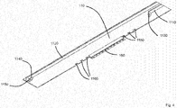
- FIG. 4 shows a detail view A from FIG. 1 in which the first locking receiving device 1150 and the two second locking receiving devices 1130, 1140 and the dovetail receiving recesses 1160 on the ground support element 110 can be seen. Also visible here are the rail-shaped guide members 1110, 1120 on which the mobile sections (not shown) can be reciprocated between the open and closed positions.
- the first locking receiving device 1150 is designed as a socket with a square cross section, whereas the second locking receiving elements 1130, 1140 are formed with a round cross section.
- the first locking element 1150 is integrally formed with the one second locking element 1140.
- the second locking elements 1130, 1140 are located along the length of the ground support element 110 at a closed position of the respective corresponding mobile sections, as can be seen in the later figures.
- FIG. 5 can be seen in detail to the second locking receiving elements (not shown) corresponding second locking elements 2130, 3140.
- the second locking elements 2130, 3140 are arranged on the inside of the mobile sections 20, 30 and extend in a cylindrical manner in the direction of the length of the ground support element 110.
- a diameter of the second locking elements 2130, 3140 corresponds to the cross section of the second locking receiving elements on the ground support element 110.
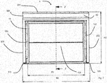
- FIG. 6 shows the weather protection device 1 according to the invention in a closed position.
- the mobile sections 20, 30 are now no longer disposed as in the open position around the trunk section 10 but away from it and tension within roof elements 101, 201, 301 and wall elements 102, 202, 302 belonging to the trunk section 10 and the mobile sections 20, 30 an interior that extends over the entire length of the bottom support members 110, 120.
- a second locking element 3150 is arranged, corresponding to the second locking receiving element.
- a locking element 3150 is the same on the inside of the other side wall 302 of the second mobile section 30 on the opposite side, which is not shown for perspective reasons. Also shown in FIG.
- side guide members 107, 207 disposed on the side walls 102, 202 of the trunk section 10 and the first mobile section 20, below the roof members 101, 102, and in the reciprocating motion between the opened and closed positions on an upper side of the weather protection device 1 provide a guide of the mobile sections 20, 30 and the trunk section 10 with each other.
- An overall height H2 of the weather protection device 1 extends from an underside of the floor support elements 110, 120 to an upper side of the roof 301 of the highest section, the second mobile section 30, above the roller box 306.
- An inner width B1 extends between inner sides of the wall elements 102, 103 narrowest section of the trunk section 10.
- a total width B2 of the weatherproof device 1 extends between outer sides of the wall elements 302, 303 of the widest section, the second mobile section 30.
- FIG. 8 shows a sectional view along the section line ZZ FIG. 7 ,
- the mobile sections 20, 30 in a direction along the length also overlap in the open position to a small extent, thus sealing an interior space spanned thereby and reliably protecting an object disposed therein from weather influences.
- An overall length L2 of the weather protection device 1 extends from the outer end of the rear wall 104 of the trunk section 10 to the opposite one
- a height H3 of an opening of the gate member extends from the bottom of the bottom support members 120 to a bottom of the roll case 306.
- Also visible in this figure is angling of the roof members 101, 201, 301 of the trunk section 10 and the mobile sections 20, 30 opposite the ground.
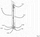
- FIG. 9 shows a detailed view C from FIG. 6 and in particular a cooperation of the first locking element 3150 with the first locking receiving element 1150 and the second locking element 3140 with the second locking receiving element 1140.
- the first locking element 3150 is fixed to the inside of the side wall 303 of the second mobile section 30 and connected to an actuating element 3151, through which Actuate the first locking member 3150 in a direction perpendicular to the ground between a locked position and an unlocked position can be moved up and down.
- the first locking element 3150 has a square cross-section corresponding to the first locking receiving element.
- the first locking member 3150 may engage the first locking receiving member 1150 by moving to the locked position.
- the second locking member 1140 engages the second locking receiving member 1150 by sliding movement of the mobile section 30 on the guide member 1120 to the closed position.
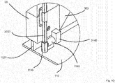
- FIG. 10 shows again in detail the engagement of the first locking element 3150 with the first locking receiving element 1150 and the second locking element 3140 with the second locking receiving element 1140
- FIG. 11 the engagement of a second locking element 2230 of the first mobile section 20 with the second locking receiving element 1230 of the ground support element 120 is shown.
- the second locking member 2230 is inserted into the locking receiving member 1230 by moving the first mobile section 20 on the guide member 1210 to the closed position so as to interlock with each other.
- interaction of the first and second locking elements and locking receiving elements and their arrangement on the ground support elements, on which turn the load receiving devices are arranged thus results in the closed position complete locking of the sections to each other and securing the entire weather protection device against movement. in every direction.
- the weather protection device is shown in the closed position with a closed gate element 305.
- the gate element 305 is arranged on the second mobile section 30 and shown here as a roller shutter. It can be lowered from the rolling box 306 and stowed therein.
- the weather protection device is thus completely closed on all sides.
- the Figures 13 and 14 show the completely closed weather protection device in the front and side view.
Landscapes
- Engineering & Computer Science (AREA)
- Architecture (AREA)
- Civil Engineering (AREA)
- Structural Engineering (AREA)
- Tents Or Canopies (AREA)
Applications Claiming Priority (1)
| Application Number | Priority Date | Filing Date | Title |
|---|---|---|---|
| DE202015105869.1U DE202015105869U1 (de) | 2015-11-04 | 2015-11-04 | Sektionale Wetterschutzvorrichtung |
Publications (1)
| Publication Number | Publication Date |
|---|---|
| EP3165692A1 true EP3165692A1 (fr) | 2017-05-10 |
Family
ID=55235368
Family Applications (1)
| Application Number | Title | Priority Date | Filing Date |
|---|---|---|---|
| EP16197246.8A Withdrawn EP3165692A1 (fr) | 2015-11-04 | 2016-11-04 | Dispositif sectionnel de protection contre les intempéries |
Country Status (2)
| Country | Link |
|---|---|
| EP (1) | EP3165692A1 (fr) |
| DE (1) | DE202015105869U1 (fr) |
Cited By (2)
| Publication number | Priority date | Publication date | Assignee | Title |
|---|---|---|---|---|
| CN106639400A (zh) * | 2017-01-05 | 2017-05-10 | 浙江省二建建设集团有限公司 | 移动式加工车间及使用方法 |
| RU240292U1 (ru) * | 2025-07-28 | 2025-12-30 | Денис Андреевич Реутов | Гаражная конструкция с функцией "матрешки" |
Citations (10)
| Publication number | Priority date | Publication date | Assignee | Title |
|---|---|---|---|---|
| FR1059516A (fr) * | 1952-07-07 | 1954-03-25 | Garage transportable pour automobiles particulières | |
| US4288949A (en) | 1979-07-18 | 1981-09-15 | John Latimer | Modular garage structure |
| DE9406075U1 (de) * | 1994-04-13 | 1994-08-11 | Tepe, Hubert, 48429 Rheine | Bewegbare Garage |
| JP2002004615A (ja) | 2000-06-21 | 2002-01-09 | Suzuki Shoji:Kk | 伸縮性車庫 |
| FR2921400A1 (fr) | 2007-09-21 | 2009-03-27 | Jacques Bois | Garage a volume variable destine aux motocyclettes et engins equivalents |
| US20100200035A1 (en) * | 2009-02-12 | 2010-08-12 | Ronald Jordache | Retractable motor vehicle shelter |
| EP2236702A1 (fr) * | 2009-04-02 | 2010-10-06 | Sportsman Corporation Co. | Garage mobile disposant d'une porte latérale |
| US20120048320A1 (en) * | 2010-08-24 | 2012-03-01 | Leslie Glenn Hardie | Automobile cover apparatus |
| WO2012127211A1 (fr) | 2011-03-18 | 2012-09-27 | Peerboom Limited | Bâtiment |
| JP2015143412A (ja) | 2014-01-31 | 2015-08-06 | 田村 智 | 二輪車用収納庫 |
-
2015
- 2015-11-04 DE DE202015105869.1U patent/DE202015105869U1/de not_active Expired - Lifetime
-
2016
- 2016-11-04 EP EP16197246.8A patent/EP3165692A1/fr not_active Withdrawn
Patent Citations (10)
| Publication number | Priority date | Publication date | Assignee | Title |
|---|---|---|---|---|
| FR1059516A (fr) * | 1952-07-07 | 1954-03-25 | Garage transportable pour automobiles particulières | |
| US4288949A (en) | 1979-07-18 | 1981-09-15 | John Latimer | Modular garage structure |
| DE9406075U1 (de) * | 1994-04-13 | 1994-08-11 | Tepe, Hubert, 48429 Rheine | Bewegbare Garage |
| JP2002004615A (ja) | 2000-06-21 | 2002-01-09 | Suzuki Shoji:Kk | 伸縮性車庫 |
| FR2921400A1 (fr) | 2007-09-21 | 2009-03-27 | Jacques Bois | Garage a volume variable destine aux motocyclettes et engins equivalents |
| US20100200035A1 (en) * | 2009-02-12 | 2010-08-12 | Ronald Jordache | Retractable motor vehicle shelter |
| EP2236702A1 (fr) * | 2009-04-02 | 2010-10-06 | Sportsman Corporation Co. | Garage mobile disposant d'une porte latérale |
| US20120048320A1 (en) * | 2010-08-24 | 2012-03-01 | Leslie Glenn Hardie | Automobile cover apparatus |
| WO2012127211A1 (fr) | 2011-03-18 | 2012-09-27 | Peerboom Limited | Bâtiment |
| JP2015143412A (ja) | 2014-01-31 | 2015-08-06 | 田村 智 | 二輪車用収納庫 |
Cited By (2)
| Publication number | Priority date | Publication date | Assignee | Title |
|---|---|---|---|---|
| CN106639400A (zh) * | 2017-01-05 | 2017-05-10 | 浙江省二建建设集团有限公司 | 移动式加工车间及使用方法 |
| RU240292U1 (ru) * | 2025-07-28 | 2025-12-30 | Денис Андреевич Реутов | Гаражная конструкция с функцией "матрешки" |
Also Published As
| Publication number | Publication date |
|---|---|
| DE202015105869U1 (de) | 2016-01-07 |
Similar Documents
| Publication | Publication Date | Title |
|---|---|---|
| EP2150663B1 (fr) | Dispositif de rangement pour véhicules à moteur | |
| EP0453409B1 (fr) | Dispositif de levage, notamment pour lits | |
| DE202008014035U1 (de) | Ladesicherung | |
| EP3165692A1 (fr) | Dispositif sectionnel de protection contre les intempéries | |
| DE2139743C2 (de) | Vorrichtung zum Parken mehrerer Fahrzeuge übereinander | |
| EP2418324B1 (fr) | Agencement de glissières de sécurité | |
| DE102009037977A1 (de) | Absperrelement, insbesondere ein Bauzaun, eine Absperrschranke oder dgl., Vorrichtung zur Verkettung von Absperrelementen und Schwenkvorrichtung zwischen zwei Absperrelementen | |
| DE3611372C2 (fr) | ||
| DE102022116124B3 (de) | Gehäuse einer elektrischen Ladesäule sowie elektrische Ladesäule | |
| EP3523161B1 (fr) | Véhicule, notamment véhicule d'intérêt général, comprenant un système de chargement | |
| DE102019209178A1 (de) | Hebebühne und Tragsäule einer Hebebühne | |
| DE102008035769C5 (de) | Fahrzeugaufbau für Nutzfahrzeuge | |
| DE102016111410A1 (de) | Mittelstütze für eine Gebäudeöffnung mit großer lichter Breite | |
| DE102017118275B4 (de) | Torvorrichtung und diese enthaltende Toranordnung | |
| AT519408B1 (de) | Überfahrbares automatisch schließendes Vertikalschott | |
| DE102008039648A1 (de) | Elemente für eine Einrichtung zur Ladungssicherung für Fahrzeuge mit einer Ladefläche | |
| DE9306706U1 (de) | Abstelleinrichtung für Fahrräder | |
| DE102013103195B4 (de) | Transportfahrzeug | |
| DE19925117B4 (de) | Isoliertrennwand-System für ein Kühlfahrzeug | |
| DE102008021669A1 (de) | Befestigungsanordnung | |
| DE102021115312A1 (de) | Garagenhubsystem | |
| WO2004067362A1 (fr) | Rancher a dispositif integre pour securiser un chargement, notamment sur des vehicules de transport baches | |
| DE2256658B2 (fr) | ||
| DE202021004351U1 (de) | Garagenhubsystem | |
| DE29903244U1 (de) | Verteilergestell |
Legal Events
| Date | Code | Title | Description |
|---|---|---|---|
| PUAI | Public reference made under article 153(3) epc to a published international application that has entered the european phase |
Free format text: ORIGINAL CODE: 0009012 |
|
| AK | Designated contracting states |
Kind code of ref document: A1 Designated state(s): AL AT BE BG CH CY CZ DE DK EE ES FI FR GB GR HR HU IE IS IT LI LT LU LV MC MK MT NL NO PL PT RO RS SE SI SK SM TR |
|
| AX | Request for extension of the european patent |
Extension state: BA ME |
|
| STAA | Information on the status of an ep patent application or granted ep patent |
Free format text: STATUS: THE APPLICATION IS DEEMED TO BE WITHDRAWN |
|
| 18D | Application deemed to be withdrawn |
Effective date: 20171111 |