EP3165696B1 - Schloss mit kuppelbarer schlossnuss - Google Patents
Schloss mit kuppelbarer schlossnuss Download PDFInfo
- Publication number
- EP3165696B1 EP3165696B1 EP16194131.5A EP16194131A EP3165696B1 EP 3165696 B1 EP3165696 B1 EP 3165696B1 EP 16194131 A EP16194131 A EP 16194131A EP 3165696 B1 EP3165696 B1 EP 3165696B1
- Authority
- EP
- European Patent Office
- Prior art keywords
- lock
- follower
- latch
- coupling
- nut
- Prior art date
- Legal status (The legal status is an assumption and is not a legal conclusion. Google has not performed a legal analysis and makes no representation as to the accuracy of the status listed.)
- Active
Links
Images


Classifications
-
- E—FIXED CONSTRUCTIONS
- E05—LOCKS; KEYS; WINDOW OR DOOR FITTINGS; SAFES
- E05B—LOCKS; ACCESSORIES THEREFOR; HANDCUFFS
- E05B65/00—Locks or fastenings for special use
- E05B65/10—Locks or fastenings for special use for panic or emergency doors
- E05B65/1086—Locks with panic function, e.g. allowing opening from the inside without a ley even when locked from the outside
-
- E—FIXED CONSTRUCTIONS
- E05—LOCKS; KEYS; WINDOW OR DOOR FITTINGS; SAFES
- E05B—LOCKS; ACCESSORIES THEREFOR; HANDCUFFS
- E05B13/00—Devices preventing the key or the handle or both from being used
- E05B13/005—Disconnecting the handle
-
- E—FIXED CONSTRUCTIONS
- E05—LOCKS; KEYS; WINDOW OR DOOR FITTINGS; SAFES
- E05B—LOCKS; ACCESSORIES THEREFOR; HANDCUFFS
- E05B15/00—Other details of locks; Parts for engagement by bolts of fastening devices
- E05B15/0013—Followers; Bearings therefor
-
- E—FIXED CONSTRUCTIONS
- E05—LOCKS; KEYS; WINDOW OR DOOR FITTINGS; SAFES
- E05B—LOCKS; ACCESSORIES THEREFOR; HANDCUFFS
- E05B63/00—Locks or fastenings with special structural characteristics
- E05B63/16—Locks or fastenings with special structural characteristics with the handles on opposite sides moving independently
Definitions
- the invention relates to a lock for a door or a window or the like according to the features of the preamble of claim 1.
- panic locks are often used to secure building access. These are locks that secure access to a building from the outside and at the same time allow you to leave the building from the inside at any time. In the event of an emergency or panic, the building can be left at any time.
- a generic lock is from the DE43 19 325 A1 known.
- a panic lock with a two-part lock nut is described.
- the outer nut can be coupled via a spring-loaded nut lever.
- the nut lever is mounted on the inner nut and has a nose that engages in a shoulder of the outer nut for coupling. This clutch remains when the nut is actuated.
- Another panic lock is out of the DE 10 2012 010 786 A1 known.
- a mortise lock with a lock bolt received in a lock housing and a three-part lock nut which interacts with a door handle.
- the lock nut is constructed in three parts, with a center nut being permanently connected to the lock mechanism and via one Coupling device either an outer nut part or an inner nut part can be coupled or uncoupled.
- a nut driver is designed as a driver lever acting directly between the outer nut and the inner nut, which is either pivotally mounted on one end on the outer nut and is supported on the other side on a support bearing arranged on the inner nut, or is pivotably supported on the inner nut at one end and is mounted on the other is supported on a support bearing arranged on the outer nut, and the driver lever uncouples the outer nut from the inner nut by a spring pivoting the driver lever into a position out of engagement with the support bearing, by the contour of the support bearing and / or the end of the driver lever cooperating with the support bearing has a beveled support surface which urges the driver lever out of engagement when the outside handle is actuated.
- the driver lever points, so to speak a preferred position in which the outer nut is separated from the inner nut.
- the device according to the invention enables the outside handle to be safely uncoupled.
- the lock according to the invention enables the space to be secured to be securely closed even in the event of a danger situation caused by a killing spree.
- the lock mechanism is prevented from jamming by actuating the lock mechanism to uncouple the outer nut.
- the external handle can be uncoupled, for example, by actuating a locking cylinder accommodated in the lock in the closing direction.
- the locking cylinder can be operated in the opening direction for coupling.
- the lock cylinder can interact with a control element or control slide mounted within the lock housing in order to control the uncoupling or the coupling.
- inside refers to the side of a door that lies in a secure room, for example a classroom in a school.
- the outside refers to the outside of a secured room, for example a hallway or an outside area of a building.
- the lock has a lock faceplate and a lock case connected to it.
- a receptacle for a lock cylinder Arranged in the lock case are a receptacle for a lock cylinder, a detachable lock nut, a latch or a latch bolt, and a control element which can be switched by a lock cylinder between a decoupled position and a coupled position.
- the detachable lock nut has an inner nut that can be connected or connected to an inner handle and an outer nut that can be connected to an outer handle.
- the control element interacts with a coupling element in order to couple and / or uncouple the outer nut.
- the lock nut is designed as a two-part nut and has an inner nut and an outer nut. A nut middle part is not necessary.
- the inner nut can be permanently connected to the lock mechanism to enable the lock to be operated at any time by the inside handle.
- the inner nut can also be designed as a detachable nut part in order to selectively couple the inner handle, i.e. to connect with the lock mechanism, or to disconnect i.e. separate from the lock mechanism.
- control element is designed as a control element which can be displaced and / or pivoted transversely to the lock faceplate.
- the control element is bistable, i.e. it can be specifically switched between the uncoupled or the engaged position. This means that the control element has a stable position both in the uncoupled position and also has a stable position in the coupled position.
- the control element is preferably completely accommodated within the lock housing.
- control element has a recess into which a resilient catch engages in the engaged position in order to fix the engaged position of the control element.
- control element has a second recess into which one is in the disengaged position spring catch engages to fix the disengaged position of the control.
- control element is designed as a control slide which is slidably mounted in the lock case via a link guide or via an elongated hole cooperating with a pin.
- a safe guidance of the control element is made possible via a link guide or an elongated hole with a pin, without the control element being able to jam or get caught in an intermediate position.
- the control element actuates a coupling element which interacts with the driving lever for coupling or uncoupling the outer nut.
- the coupling element is designed as a coupling slide that can be moved parallel to the faceplate, one end of which cooperates directly with the driving lever and the other end directly with the control lever.
- the end of the coupling element interacting with the driving lever has a support surface or drainage surface, the contour of which is adapted to a round contour of the lock nut.
- the driver lever is supported in the engaged position on the support surface or drainage surface in order to prevent the outer nut from being uncoupled.
- the driver lever is pushed into the engaged position by the support surface or drain surface.
- the coupling element interacts with the driver lever in such a way that it remains securely coupled in the engaged position and thus prevents the outer nut from being uncoupled.
- the drainage surface or support surface extends over a circular section which is the same size or larger than the maximum rotation angle of the lock nut, preferably covering a circular section in the range of a rotation angle of 15 ° to 70 °.
- the coupling element thus has, so to speak, a slide bearing on which the driver lever slides, which ensures uniform support of the driver lever over the entire range of rotation of the lock nut and thereby ensures that the outer nut remains in the engaged position.
- the coupling element is connected to a coupling spring mounted in the lock case, which acts on the coupling element in the uncoupled position the movement path of the driver lever is led out.
- a coupling spring mounted in the lock case acts on the coupling element in the uncoupled position the movement path of the driver lever is led out.
- the coupling element is designed as a coupling slide, which is displaceably mounted parallel to the faceplate is.
- this means that the coupling slide is not only spring-loaded, but also supported by its weight force in the uncoupled position. This enables a particularly safe disengagement of the lock.
- control element interacts with the coupling element via a bevelled guide surface in order to displace it against the force of the coupling spring for coupling.
- the inner nut is permanently coupled to the trap or a trap mechanism actuating the trap.
- the latch is designed as a lockable latch or as a latch bolt.
- the trap can be designed, for example, as a cross trap or as a tilt trap.
- the trap can also be designed as a so-called shooting trap that excludes spring-loaded from the lock housing. It is thereby achieved that when the door is closed, the lock automatically keeps the door in the closed position via the latch, and access to the secured space is therefore no longer possible, at least from the outside.
- the latch can be locked, ie it cannot be pushed back into the lock housing even in the event of a mechanical attack on the latch.
- the lock case has a change in order to unlock and / or withdraw the latch both via the lock cylinder and via a door handle.
- the change it is possible to open the lock from the outside as well as from the inside by means of a locking cylinder. An authorized person can therefore enter the secure room from the outside at any time using a key.
- a lock cylinder is accommodated in the lock cylinder receptacle, which can be actuated from the inside via an inside handle, preferably a rotary knob, and from the outside via a key.
- the lock cylinder does not actuate a lock bolt. It primarily controls the uncoupling or uncoupling of the outer nut or the outer handle.
- the locking cylinder has a slip clutch in order to separate the inside handle in the event of a blockage.
- the slip clutch prevents access to the secured space from being blocked from the inside, for example by blocking the handle of the locking cylinder.
- the slip clutch enables the lock to be opened from the outside even if the handle is blocked on the inside.
- the lock has no dead bolt.
- many components of the Lock mechanism which could otherwise possibly cause the latch mechanism and / or the lock nut to become blocked or jammed.
- a fixing or blocking of the driver lever by means of a screw is not possible in the lock according to the invention, in order to enable the outer nut to be uncoupled at any time.
- the Figures 1-5 show a possible embodiment of the lock 1.
- the same parts of the lock are each provided with the same reference numerals.
- the Fig. 1 shows a schematic view of the lock 1 according to the invention installed in a wing of a door in a building.
- the lock 1 is designed as a mortise lock and sits in a tab of the door leaf.
- the lock is connected to two door handles, on the inside of the secured room with an interior door handle 7i and on the Outside with an outside door handle 7a.
- a locking cylinder 6 is accommodated in a locking cylinder receptacle of the lock 1 and can be operated from the inside by means of a rotary knob 61.
- the lock 1 In a starting position, the lock 1 can be operated and opened from both sides using the lever handle. If required, the outside door handle 7a can be uncoupled from the inside, ie from the secured space. Uncoupling is done by turning the hand knob 61, as in Fig. 1 shown in the direction of the arrow. This makes it possible to lock the lock 1 from the secured room in such a way that the door cannot be opened from the outside. Uncoupling the outside door handle 7a is also possible especially when the outside door handle 7a has already been actuated.
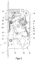
- the lock 1 is shown with the lock cover removed.
- the lock has a lock case 12 and a lock face plate 11.
- Arranged in the lock case 12 are the elements of the lock mechanism as well as a latch 2 reaching through the face plate and a control latch 16 reaching through the face plate.
- the lock case 12 has in its lower area a receptacle 18 for a lock cylinder, not shown.
- a lock nut 4 is arranged above the locking cylinder.
- the lock nut 4 is designed as a split lock nut and has, as in Fig. 5 shown, an inner nut 4i and an outer nut 4a.
- a door handle can be inserted into the lock nut 4 by means of a handle pin.
- a spiral spring 14 is arranged in the lock case 12 above the lock nut 4 and serves as a return spring for the lever handle.
- the lock nut 4 has a latch driver 44 which interacts with the latch 2 in order to withdraw them into the lock housing 12 for unlocking.
- the latch 2 is designed as a shooting latch and is acted upon or pushed out of the lock housing 12 by a latch spring 21.
- a control latch 16 is arranged above the lock latch 2.
- the control latch 16 interacts with a latch locking mechanism in order to lock the latch 2 when the door is locked.
- the latch locking mechanism has a slide plate which can be moved parallel to the faceplate and which is used to lock the latch downwards, ie into the in Fig. 2 position shown is movable.
- a front edge of the slide plate is on the rear side of the latch body and prevents the latch 2 from being pressed back into the lock housing 12. A secure locking in the closed position of the door to
- the lock 1 can be unlocked, for example, via a locking cylinder inserted into the locking cylinder receptacle 18.
- a change lever 17 is actuated, by means of which the slide plate 22 is moved upward parallel to the face plate and thereby releases the latch 2.
- the change lever 17 pulls the latch 2 back into the lock housing 12 via a pivot lever 17a.
- An alternative way of opening the lock 1 is via the inside door handle 7i.
- the door handle 7i is connected to the inner nut 4i.
- the inner nut 4i is rotated clockwise.
- the slide plate 22 is lifted by a cam of the inner nut and at the same time the latch 2 is retracted into the lock housing 12 via the latch driver 44.
- the lock can also be opened from the outside via the door handle 7a connected to the outer nut 4a.
- the lock nut 4 is in the Fig. 4 shown as an assembly.
- the lock nut 4 has a receptacle for a handle pin in the middle.
- the inside 4i of the lock nut is permanently connected to the lock mechanism in order to actuate the latch 2.
- the outer nut 4a of the two-part lock nut 4 can optionally be connected or disconnected.
- a nut driver 41 arranged between the outer nut part 4a and the inner nut part 4i is provided for coupling or uncoupling the outer nut part 4a.
- the nut driver 41 is pivotally mounted on the outer nut part 4a.
- the outer nut part 4a has a pin which engages in a bore in the nut driver 41.
- the pin forms a pivot bearing for the nut driver lever 41.
- a driver spring 42 is arranged in the area of the pivot bearing.
- the driver spring 42 acts on the nut driver 41 to the outside, ie out of the lock nut 4.
- the engaged position of the nut driver 41 is shown.
- the nut driver 41 In the coupled position, the nut driver 41 is supported on the support bearing 43 on the inner nut 4i.
- the outer nut 4a is connected in a rotationally fixed manner to the inner nut 4i via the driving lever 41.
- the driver lever 41 has a bevelled outer contour in the region of the support bearing, which is designed such that the driver lever 41 is forced out of engagement with the support bearing 43 by the rotation of the outer nut 4a.
- the lock is shown with the outer nut engaged.
- the lock 1 has a cross mounted to the faceplate 11 slidably Control spool 3 on.
- the control slide 3 is slidably mounted in the lock housing 12 via an elongated hole 32 and a pin 15.
- the spool 3 points at its in the Fig. 2 right end on a guide surface 33 which is inclined and cooperates with a clutch slide 5.
- the clutch slide 5 is supported against the force of the clutch spring 52 on the top of the control slide 3.
- the control slide 3 is fixed in this engaged position by a resilient catch 13.
- the resilient catch 13 engages in a recess 31 arranged on the control slide 3.
- the clutch slide 5 cooperates at its upper end with the nut driver 41.
- the clutch slide 5 has a drain surface 51 at its upper end.
- the drain surface 51 is rounded and complementary to the round lock nut 4.
- the nut driver 41 is supported on the drain surface, which in turn urges the nut driver 41 against the force of the driver spring 42 against the lock nut 4 to engage it.
- the driver lever 41 in the Fig. 2 or 4 shown coupled position fixed.
- the round design of the run-off surface 51 ensures that the engagement of the follower lever 41 with the support bearing 43 is ensured over the entire rotation angle range of the lock nut.
- the lock is shown in the uncoupled position of the outer nut 4a.
- the control slide 3 is shifted to the left, ie towards the face plate 11.
- the control spool 3 is displaced via a locking cylinder (not shown).
- the locking cylinder is inserted in the locking cylinder receptacle 18 and engages with its locking lug in a recess in the control slide.
- When closing ie when Turning the lock cylinder counterclockwise moves the control spool 3 to the left.
- the coupling element 5 acted upon by the coupling spring 52 slides along the inclined guide surface 33.
- the upper end of the coupling element 5 moves away from the lock nut 4.
- the guide surface 51 releases the driver lever 41.
- the driver spring 42 pivots the driver lever 41 about its pivot bearing so that it disengages from the support bearing 43.
- the rotationally fixed connection between the outer nut part 4a and the inner nut part 4i is canceled, so that the outer nut part 4a can rotate freely.
- the connection of the outside door handle 7a with the lock mechanism is released, so that the lock 1 can no longer be opened from the outside.
- Uncoupling the outer door nut 4a is possible in any position of the lock nut 4 or the inner nut part or the outer nut part. Even if the outside door handle is already actuated, it is ensured that the driving lever 41 is pressed out of engagement via the driving spring 42 and thus the outer nut part 4a is uncoupled. Even if, in an emergency, the inside door handle 7a is held against an opening force applied from the outside, i.e. an increased clamping force occurs, the oblique contour of the driving lever 41 ensures that it is disengaged from the support bearing 43 and the outside nut 4a is securely removed the inner nut 4i uncouples. This means that the door can be locked securely in any situation from within a secured room.
Landscapes
- Business, Economics & Management (AREA)
- Emergency Management (AREA)
- Engineering & Computer Science (AREA)
- Structural Engineering (AREA)
- Lock And Its Accessories (AREA)
Description
- Die Erfindung betrifft ein Schloss für eine Tür oder ein Fenster oder dergleichen gemäß den Merkmalen des Oberbegriffs des Anspruchs 1.
- Zur Sicherung von Gebäudezugängen werden in der Praxis oftmals sogenannte Panikschlösser eingesetzt. Es handelt sich dabei um Schlösser, die den Zugang zu einem Gebäude von Außen sicher verschließen und gleichzeitig von Innen jederzeit ein Verlassen des Gebäudes ermöglichen. So kann im Falle eines Notfalls oder im Falle einer Panik das Gebäude jederzeit verlassen werden.
- Ein gattungsgemäßes Schloss ist aus der
DE43 19 325 A1 bekannt. Dort ist ein Panikschloss mit einer zweigeteilten Schlossnuss beschrieben. Die Außennuss kann über einen federbelasteten Nusshebel aufgekuppelt werden. Der Nusshebel ist an der Innennuss gelagert und weist eine Nase auf, die zum Kuppeln in eine Schulter der Außennuss eingreift. Bei einer Betätigung der Nuss bleibt diese Kupplung bestehen. - Ein weiteres Panikschloss ist aus der
DE 10 2012 010 786 A1 bekannt. Dort ist ein Einsteckschloss mit einem in einem Schlossgehäuse aufgenommenen Schlossriegel und einer mit einem Türdrücker zusammenwirkenden dreiteiligen Schlossnuss gezeigt. Zum Abkuppeln eines Türdrückers ist die Schlossnuss dreiteilig aufgebaut, wobei eine Mittennuss mit der Schlossmechanik dauerhaft verbunden ist und über eine Kupplungseinrichtung entweder ein Außennussteil oder ein Innennussteil auf- bzw. abgekuppelt werden kann. - Um eine Sicherung von einzelnen Räumen in Gebäuden, beispielsweise eine Sicherung von Klassenzimmern auch im Falle eines Amokalarms zu gewährleisten, ist es notwendig, ein Schloss zu schaffen, welches unter allen Umständen ein Verschließen des Raumes ermöglicht. Im Rahmen einer Gefährdungssituation kann es beispielsweise vorkommen, dass gefährdete Personen in einen Raum flüchten, dessen Zugangstür unter allen Umständen abschließbar sein muss, um das Eindringen unerwünschter Personen zu unterbinden.
- Es ist die Aufgabe der vorliegenden Erfindung ein Schloss zu schaffen, welches auch bei bereits betätigtem Türdrücker immer ein sicheres Verschließen eines gesicherten Raumes ermöglicht.
- Diese Aufgabe wird erfindungsgemäß durch ein Schloss mit den Merkmalen des Anspruchs 1 gelöst. Es ist vorgesehen, dass ein Nussmitnehmer als direkt zwischen Außennuss und Innennuss wirkender Mitnehmerhebel ausgebildet ist, der entweder einerends an der Außennuss schwenkbar gelagert ist und sich andernends an einem an der Innennuss angeordneten Stützlager abstützt, oder einerends an der Innennuss schwenkbar gelagert ist und sich andernends an einem an der Außennuss angeordneten Stützlager abstützt, und der Mitnehmerhebel die Außennuss von der Innennuss abkuppelt, indem eine Feder den Mitnehmerhebel in eine Position außer Eingriff mit dem Stützlager schwenkt, indem die Kontur des Stützlagers und/oder das mit dem Stützlager zusammenwirkende Ende des Mitnehmerhebels eine abgeschrägte Stützfläche aufweist, die den Mitnehmerhebel bei Betätigung des Außendrückers außer Eingriff drängt. Der Mitnehmerhebel weist sozusagen eine Vorzugstellung auf, bei der die Außennuss von der Innennuss abgetrennt ist. Selbst bei einer Betätigung des Außendrückers, also in einer Situation, bei der ein Verfolger bereits den Türdrücker betätigt, um einen gesicherten Raum zu öffnen, wird über die erfindungsgemäße Vorrichtung ein sicheres Abkuppeln des Außendrückers ermöglicht. Dadurch ist über das erfindungsgemäße Schloss auch im Falle einer durch Amoklauf hervorgerufenen Gefährdungssituation ein sicheres Verschließen des zu sichernden Raumes möglich. Ein Verklemmen der Schlossmechanik wird verhindert, indem eine Betätigung der Schlossmechanik ein Abkuppeln der Außennuss bewirkt. Ein Abkuppeln des Außendrückers kann beispielsweise durch die Betätigung eines in dem Schloss aufgenommenen Schließzylinders in Schließrichtung erfolgen. Zum Ankuppeln kann der Schließzylinder in Öffnungsrichtung betätigt werden. Der Schließzylinder kann mit einem innerhalb des Schlossgehäuses gelagerten Steuerelement oder Steuerschieber zusammenwirken um das Abkuppeln oder das Ankuppeln zu steuern.
- Innenseite bezeichnet in diesem Zusammenhang diejenige Seite einer Tür, die in einem gesicherten Raum, beispielsweise einem Klassenzimmer in einer Schule, liegt. Die Außenseite bezeichnet in diesem Zusammenhang die Außenseite eines gesicherten Raumes, beispielsweise ein Flur oder ein Außenbereich eines Gebäudes.
- Das Schloss weist einen Schlossstulp und einen mit diesem verbundenen Schlosskasten auf. In dem Schlosskasten sind eine Aufnahme für ein Schließzylinder, eine kuppelbare Schlossnuss, eine Falle oder ein Fallenriegel, sowie ein von einem Schließzylinder zwischen einer abgekuppelten Stellung und einer eingekuppelten Stellung schaltbares Steuerelement angeordnet.
- Die kuppelbare Schlossnuss weist eine mit einem Innendrücker verbindbare oder verbundene Innennuss und eine mit einem Außendrücker verbindbare Außennuss auf. Das Steuerelement wirkt mit einem Kupplungselement zusammenwirkt um die Außennuss aufzukuppeln und/oder abzukuppeln. Die Schlossnuss ist als zweiteilige Nuss ausgebildet und weist eine Innenuss und eine Außennuss auf. Ein Nussmittenteil ist nicht notwendig. Die Innennuss kann dauerhaft mit der Schlossmechanik verbunden sein um jederzeit eine Betätigung des Schlosses durch den Innendrücker zu ermöglichen. In anderer Ausgestaltung kann die Innennuss auch als kuppelbares Nussteil ausgebildet sein um den Innendrücker wahlweise aufzukuppeln, d.h. mit der Schlossmechanik zu verbinden, oder abzukuppeln d.h. von der Schlossmechanik zu trennen.
- In einer Ausgestaltung ist vorzugsweise vorgesehen, dass das Steuerelement als ein quer zu dem Schlossstulp verschiebbares und/oder verschwenkbares Steuerelement ausgebildet ist. Das Steuerelement ist bistabil ausgebildet, d.h. es ist gezielt zwischen der abgekuppelten oder der eingekuppelten Stellung schaltbar. Das bedeutet, dass das Steuerelement sowohl in abgekuppelter Stellung eine stabile Lage aufweist als auch in der einkuppelten Stellung eine stabile Lage aufweist. Das Steuerelement ist vorzugsweise vollständig innerhalb des Schlossgehäuses aufgenommen.
- Um eine Sicherung der eingekuppelten Stellung des Steuerelements zu bewerkstelligen, kann vorgesehen sein, dass das Steuerelement eine Ausnehmung aufweist, in die in der eingekuppelten Stellung eine federnde Raste eingreift, um die eingekuppelte Stellung des Steuerelements zu fixieren. Alternativ oder ergänzend kann auch vorgesehen sein, dass das Steuerelement eine zweite Ausnehmung aufweist, in die in der ausgekuppelten Stellung eine federnde Raste eingreift, um die ausgekuppelte Stellung des Steuerelements zu fixieren.
- In einer Ausgestaltung kann vorgesehen sein, dass das Steuerelement als Steuerschieber ausgebildet ist, der in dem Schlosskasten über eine Kulissenführung oder über ein mit einem Zapfen zusammenwirkenden Langloch verschiebbar gelagert ist. Über eine Kulissenführung bzw. über ein Langloch mit einem Zapfen wird eine sichere Führung des Steuerelements ermöglicht, ohne dass das Steuerelement sich verklemmen kann oder in einer Zwischenstellung hängen bleibt.
- Das Steuerelement betätigt ein Kupplungselement, das mit dem Mitnehmerhebel zum Kuppeln oder Abkuppeln der Außennuss zusammenwirkt. Insbesondere kann vorgesehen sein, dass das Kupplungselement als ein parallel zum Stulp verschiebbarer Kupplungsschieber ausgebildet ist, dessen eines Ende direkt mit dem Mitnehmerhebel und dessen anderes Ende direkt mit dem Steuerhebel zusammenwirkt.
- Um bei eingekuppelter Stellung ein sicheres Betätigen des Schlosses von Außen zu ermöglichen, kann beispielsweise vorgesehen sein, dass das mit dem Mitnehmerhebel zusammenwirkende Ende des Kupplungselements eine Stützfläche oder Ablauffläche aufweist, deren Kontur an eine runde Kontur der Schlossnuss angepasst ist. Auf der Stützfläche oder Ablauffläche stützt sich der Mitnehmerhebel in eingekuppelter Stellung ab, um dadurch ein Abkuppeln der Außennuss zu vermeiden. Der Mitnehmerhebel wird durch die Stützfläche oder Ablauffläche in die Eingekuppelte Stellung gedrängt.
- Da der Mitnehmerhebel der Schlossnuss eine Vorzugstellung aufweist, die ein Abkuppeln der Außennuss bedeutet, wirkt das Kupplungselement so mit dem Mitnehmerhebel zusammen, dass in der eingekuppelten Stellung dieser sicher eingekuppelt verbleibt und damit ein unerwünschtes Abkuppeln der Außennuss vermieden wird. Dabei kann insbesondere vorgesehen sein, dass die Ablauffläche oder Stützfläche sich über einen Kreisabschnitt erstreckt, der gleich groß oder größer als der maximale Drehwinkel der Schlossnuss ist, vorzugsweise einen Kreisabschnitt im Bereich eines Drehwinkels von 15° bis 70° abdeckt. Das Kupplungselement weist somit sozusagen ein Gleitlager auf, auf dem der Mitnehmerhebel abgleitet, welches über den gesamten Drehbereich der Schlossnuss eine gleichmäßige Abstützung des Mitnehmerhebels gewährleistet und dadurch sicherstellt, dass die Außennuss in eingekuppelter Stellung verbleibt.
- In einer Ausgestaltung ist vorzugsweise vorgesehen, dass das Kupplungselement mit einer im Schlosskasten gelagerten Kupplungsfeder verbunden ist, die das Kupplungselement in die abgekuppelte Stellung beaufschlagt, Über die Kupplungsfeder ist gewährleistet, dass bei abgekuppelter Stellung das Kupplungselement außer Eingriff mit dem Mitnehmerhebel gelangt, bzw. aus der Bewegungsbahn des Mitnehmerhebels herausgeführt wird. Dadurch kann der Mitnehmerhebel frei ausschwenken, um die Außennuss von der Innennuss abzukoppeln. D. h. das Kupplungselement wird vollständig aus der Bewegungsbahn des Mitnehmerhebels herausgeführt, so dass dieser frei ausschwenken kann und somit ein Verklemmen oder Hängenbleibes des Mitnehmerhebels nicht möglich ist.
- Vorteilhafterweise kann vorgesehen sein, dass das Kupplungselement als Kupplungsschieber ausgebildet ist, der parallel zum Stulp verschiebbar gelagert ist. In bevorzugter Einbaulage des Schlosskastens, bei der Stulp vertikal verläuft, bedeutet dies, dass der Kupplungsschieber nicht nur federbeaufschlagt, sondern zusätzlich auch durch seine Gewichtskraft unterstützt in die abgekuppelte Stellung beaufschlagt wird. Dies ermöglicht ein besonders sicheres Auskuppeln des Schlosses.
- In einer Ausgestaltung kann vorgesehen sein, dass das Steuerelement über eine abgeschrägte Führungsfläche mit dem Kupplungselement zusammenwirkt, um dieses zum Aufkuppeln entgegen der Kraft der Kupplungsfeder zu verschieben.
- Um ein Öffnen des Schlosses von der Innenseite, d.h. aus dem gesicherten Raum heraus jederzeit zu ermöglichen, kann vorgesehen sein, dass die Innennuss dauerhaft mit der Falle oder eine die Falle betätigenden Fallenmechanik gekuppelt ist.
- In einer Ausgestaltung ist vorgesehen, dass die Falle als sperrbare Falle oder als Fallenriegel ausgebildet ist. Die Falle kann beispielsweise als Kreuzfalle oder als Kippfalle ausgebildet sein. Die Falle kann auch als federbelastet aus dem Schlossgehäuse ausschließende, sogenannte schießende Falle ausgebildet sein. Dadurch wird erreicht, dass bei Schließen der Tür das Schloss über die Falle automatisch die Tür in Schließlage hält und somit der Zugang zu dem gesicherten Raum zumindest von Außen nicht mehr möglich ist. Zur Erhöhung der Sicherheit kann die Falle gesperrt werden, d.h. dass sie selbst bei einem mechanischen Angriff auf die Falle selbst nicht mehr in das Schlossgehäuse zurückdrückbar ist.
- Um eine komfortable Bedienung des Schlosses zu ermöglichen, kann vorgesehen sein, dass der Schlosskasten einen Wechsel aufweist, um die Falle sowohl über den Schließzylinder als auch über einen Türdrücker zu entsperren und/oder zurückzuziehen. Über den Wechsel ist es möglich, das Schloss mittels eines Schließzylinders sowohl von der Außenseite als auch von der Innenseite zu öffnen. Somit kann eine berechtigte Person mittels eines Schlüssels von der Außenseite jederzeit in den gesicherten Raum eintreten.
- Um eine Betätigung des Schlosses von der gesicherten Seite aus jederzeit zu ermöglichen, kann vorgesehen sein, dass in der Schließzylinderaufnahme ein Schließzylinder aufgenommen ist, der von der Innenseite über eine Innenhandhabe, vorzugsweise einen Drehknauf, und von der Außenseite über einen Schlüssel betätigbar ist. Insbesondere betätigt der Schließzylinder keinen Schloßriegel. Er steuert in erster Linie das Abkuppeln oder Aufkuppeln des Außennuss bzw. des Außendrückers.
- Um einer berechtigten Person über einen Schlüssel jederzeit Zugang zu dem gesicherten Raum zu ermöglichen, kann vorgesehen sein, dass der Schließzylinder eine Rutschkupplung aufweist, um die Innenhandhabe bei einer Blockierung abzutrennen. Über die Rutschkupplung wird vermieden, dass der Zutritt zu dem gesicherten Raum von der Innenseite her blockierbar ist, indem beispielsweise die Handhabe des Schließzylinders blockiert wird. Die Rutschkupplung ermöglicht selbst im Falle einer Blockierung der Handhabe an der Innenseite von Außen eine Öffnung des Schlosses.
- Um eine Verklemmung des Schlosses zu vermeiden ist in einer Ausgestaltung vorgesehen, dass das Schloss keinen Schlossriegel (Deadbolt) aufweist. Durch den Wegfall des Schlossriegels entfallen viele Komponenten der Schlossmechanik, die ansonsten möglicherweise eine Blockierung oder eine Verklemmung der Fallenmechanik und/oder der Schlossnuss bewirken könnten. Auch eine Festlegung oder Blockierung des Mitnehmerhebels über eine Schraube, wie es beispielsweise bei herkömmlichen Panikschlössern üblich ist um eine Panikseite auszuwählen, ist bei dem erfindungsgemäßen Schloss nicht möglich, um jederzeit ein Abkuppeln der Außennuss zu ermöglichen.
- Weitere Vorteile und Ausgestaltungen der Erfindung sind in den Figuren gezeigt und nachfolgend beschrieben. Dabei zeigen:
- Fig. 1:
- eine schematische Darstellung des erfindungsgemäßen Schlosses eingebaut in einer Tür
- Fig. 2:
- das Schloss in einer Draufsicht mit eingekuppeltem Außendrücker
- Fig. 3:
- das Schloss in einer Draufsicht mit abgekuppeltem Außendrücker
- Fig. 4:
- eine Darstellung der kuppelbaren Schlossnuss
- Fig. 5:
- eine Explosionsdarstellung der Schlossnuss
- Die
Figuren 1-5 zeigen eine mögliche Ausgestaltung des erfindungsgemäßen Schlosses 1. Gleiche Teile des Schlosses sind jeweils mit gleichen Referenzzeichen versehen. DieFig. 1 zeigt eine schematische Ansicht des erfindungsgemäßen Schlosses 1 eingebaut in einem Flügel einer Tür in einem Gebäud. Das Schloss 1 ist als Einsteckschloss ausgebildet und sitzt in einer Lasche des Türflügels. Das Schloss ist mit zwei Türdrückern verbunden, auf der Innenseite des gesicherten Raumes mit einem Innentürdrücker 7i und auf der Außenseite mit einem Außentürdrücker 7a. In einer Schließzylinderaufnahme des Schlosses 1 ist ein Schließzylinder 6 aufgenommen, der von der Innenseite aus mittels Drehknauf 61 bedient werden kann. - In einer Ausgangsstellung kann das Schloss 1 von beiden Seiten über den Türdrücker bedient und geöffnet werden. Von der Innenseite, d.h. von dem gesicherten Raum aus, kann der Türaußendrücker 7a bei Bedarf abgekuppelt werden. Das Abkuppeln erfolgt durch Drehen des Handknaufs 61, wie in
Fig. 1 dargestellt in Pfeilrichtung. Dadurch ist es möglich, das Schloss 1 von dem gesicherten Raum aus so zu verriegeln, dass von der Außenseite keine Öffnung der Tür möglich ist. Das Abkuppeln des Türaußendrückers 7a ist vor allem auch dann möglich, wenn der Türaußendrücker 7a bereits betätigt wurde. - In der
Fig. 2 ist das Schloss 1 mit abgenommenem Schlossdeckel dargestellt. Das Schloss weist einen Schlosskasten 12 und einen Schlossstulp 11 auf. In dem Schlosskasten 12 sind die Elemente der Schlossmechanik sowie eine durch den Stulp hindurchgreifende Falle 2 und eine durch den Stulp hindurchgreifende Steuerfalle 16 angeordnet. Der Schlosskasten 12 weist in seinem unteren Bereich eine Aufnahme 18 für einen nicht dargestellten Schließzylinder auf. Oberhalb des Schließzylinders ist eine Schlossnuss 4 angeordnet. Die Schlossnuss 4 ist als geteilte Schlossnuss ausgebildet und weist, wie inFig. 5 dargestellt, eine Innennuss 4i und eine Außennuss 4a auf. - In die Schlossnuss 4 kann ein Türdrücker mittels eines Drückerdorns eingesetzt werden. Oberhalb der Schlossnuss 4 ist eine Spiralfeder 14 im Schlosskasten 12 angeordnet, die als Rückstellfeder für den Türdrücker dient. Die Schlossnuss 4 weist einen Fallenmitnehmer 44 auf, der mit der Falle 2 zusammenwirkt, um diese zum Entriegeln in das Schlossgehäuse 12 zurückzuziehen. Die Falle 2 ist als schießende Falle ausgebildet und wird von einer Fallenfeder 21 aus dem Schlossgehäuse 12 heraus beaufschlagt bzw. herausgedrängt. Oberhalb der Schlossfalle 2 ist eine Steuerfalle 16 angeordnet. Die Steuerfalle 16 wirkt mit einer Fallensperrmechanik zusammen, um die Falle 2 bei verriegelter Tür zu sperren. Die Fallensperrmechanik weist eine parallel zum Stulp verschiebbare Schieberplatte auf, die zum Verriegeln der Falle nach unten, d.h. in die in
Fig. 2 dargestellte Position verfahrbar ist. Dabei steht eine Vorderkante der Schieberplatte an der hinteren Seite des Fallenkörpers an diesem an und verhindert, dass die Falle 2 in das Schlossgehäuse 12 zurückgedrückt werden kann. Dadurch wird eine sichere Verriegelung in Schließlage der zu sichernden Tür erzielt. - Um die Verriegelung des Schlosses 1 zu lösen und letztendlich die Tür zu öffnen, kann beispielsweise über einen in die Schließzylinderaufnahme 18 eingesetzten Schließzylinder das Schloss 1 aufgeschlossen werden. Dabei wird ein Wechselhebel 17 betätigt, über den die Schieberplatte 22 parallel zum Stulp nach oben verfahren wird und dadurch die Falle 2 freigibt. Gleichzeitig zieht der Wechselhebel 17 über einen Schwenkhebel 17a die Falle 2 in das Schlossgehäuse 12 zurück.
- Eine alternative Möglichkeit zum Öffnen des Schlosses 1 besteht über den Türinnendrücker 7i. Der Türinnendrücker 7i ist mit der lnnennuss 4i verbunden. Durch Betätigung des Türinnendrückers 7i, der in den
Figuren 2 und3 nicht dargestellt ist, wird die Innennuss 4i im Uhrzeigersinn gedreht. Dabei wird die Schieberplatte 22 von einem Nocken der Innennuss angehoben und gleichzeitig über den Fallenmitnehmer 44 die Falle 2 in das Schlossgehäuse 12 zurückgezogen . - Bei eingekuppeltem Außennussteil 4a kann auch über den mit der Außennuss 4a verbundenen Türdrücker 7a das Schloss von Außen geöffnet werden.
- Die Schlossnuss 4 ist in der
Fig. 4 als Baugruppe dargestellt. Die Schlossnuss 4 weist mittig eine Aufnahme für einen Drückerdorn auf. Die Innenseite 4i der Schlossnuss ist permanent mit der Schlossmechanik verbunden, um die Falle 2 zu betätigen. Die Außennuss 4a der zweiteiligen Schlossnuss 4 ist wahlweise auf- oder abkuppelbar. Zum Auf- oder Abkuppeln des Außennussteils 4a ist ein zwischen Außennussteil 4a und Innennussteil 4i angeordneter Nussmitnehmer 41 vorgesehen. Der Nussmitnehmer 41 ist an dem Außennussteil 4a schwenkbar gelagert. Wie inFig. 5 dargestellt ist, weist das Außennussteil 4a dafür einen Zapfen auf, der in eine Bohrung des Nussmitnehmers 41 eingreift. Der Zapfen bildet ein Schwenklager für den Nussmitnehmerhebel 41 aus. Im Bereich des Schwenklagers ist, wie inFig. 4 dargestellt, eine Mitnehmerfeder 42 angeordnet. Die Mitnehmerfeder 42 beaufschlagt den Nussmitnehmer 41 nach Außen, d.h. aus der Schlossnuss 4 heraus. - In der
Fig. 4 ist die eingekuppelte Position des Nussmitnehmers 41 dargestellt. In der eingekoppelten Position stützt sich der Nussmitnehmer 41 auf dem Stützlager 43 an der Innennuss 4i ab. Dadurch ist die Außennuss 4a mit der Innennuss 4i über den Mitnehmerhebel 41 drehfest verbunden. Der Mitnehmerhebel 41 weist im Bereich des Stützlagers eine abgeschrägte Außenkontur auf, die so ausgebildet ist, dass der Mitnehmerhebel 41 durch die Drehung der Außennuss 4a außer Eingriff mit dem Stützlager 43 gedrängt wird. - In der
Fig. 2 ist das Schloss mit eingekuppelter Außennuss dargestellt. Das Schloss 1 weist einen Quer zum Stulp 11 verschiebbar gelagerten Steuerschieber 3 auf. Der Steuerschieber 3 ist über ein Langloch 32 und einen Zapfen 15 in dem Schlossgehäuse 12 verschiebbar gelagert. Der Steuerschieber 3 weist an seinem in derFig. 2 rechten Ende eine Führungsfläche 33 auf, die schräg geneigt ist und mit einem Kupplungsschieber 5 zusammenwirkt. In der in derFig. 2 dargestellten eingekuppelten Stellung stützt sich der Kupplungsschieber 5 entgegen der Kraft der Kupplungsfeder 52 auf der Oberseite des Steuerschiebers 3 ab. Der Steuerschieber 3 ist in dieser eingekuppelten Stellung durch eine federnde Raste 13 fixiert. Die federnde Raste 13 greift in eine am Steuerschieber 3 angeordnete Ausnehmung 31 ein. - Der Kupplungsschieber 5 wirkt an seinem oberen Ende mit dem Nussmitnehmer 41 zusammen. Der Kupplungsschieber 5 weist an seinem oberen Ende eine Ablauffläche 51 auf. Die Ablauffläche 51 ist abgerundet ausgebildet und komplementär zu der runden Schlossnuss 4 ausgebildet. Der Nussmitnehmer 41 stützt sich auf der Ablauffläche ab, wobei diese wiederum zum Einkuppeln den Nussmitnehmer 41 entgegen der Kraft der Mitnehmerfeder 42 beaufschlagt gegen die Schlossnuss 4 drängt. Dadurch wird der Mitnehmerhebel 41 in der in den
Fig. 2 oder4 dargestellten gekuppelten Stellung fixiert. Durch die runde Ausgestaltung der Ablauffläche 51 wird sichergestellt, dass über den gesamten Drehwinkelbereich der Schlossnuss der Eingriff des Nussmitnehmerhebels 41 mit dem Stützlager 43 gewährleistet ist. - In der
Fig. 3 ist das Schloss in abgekuppelter Stellung der Außennuss 4a dargestellt. Der Steuerschieber 3 ist nach links, d.h. in Richtung zum Stulp 11 hin verlagert. Die Verlagerung des Steuerschiebers 3 erfolgt über einen nicht dargestellten Schließzylinder. Der Schließzylinder ist in der Schließzylinderaufnahme 18 eingesetzt und greift mit seiner Schließnase in eine Ausnehmung des Steuerschiebers ein. Beim Abschließen, d.h. beim Drehen des Schließzylinders entgegen der Uhrzeigerrichtung wird der Steuerschieber 3 nach links verlagert. Bei der Verlagerung des Steuerschiebers gleitet das von der Kupplungsfeder 52 beaufschlagte Kupplungselement 5 auf der schrägen Führungsfläche 33 entlang. Dabei entfernt sich das Kupplungselement 5 mit seinem oberen Ende von der Schlossnuss 4. Die Führungsfläche 51 gibt dabei den Mitnehmerhebel 41 frei. Die Mitnehmerfeder 42 schwenkt dabei den Mitnehmerhebel 41 um sein Schwenklager, sodass dieser außer Eingriff mit dem Stützlager 43 gelangt. Dadurch wird die drehfeste Verbindung zwischen Außennussteil 4a und Innennussteil 4i aufgehoben, sodass sich das Außennussteil 4a frei drehen kann. Durch das Abkuppeln der Außennuss 4a wird die Verbindung des Türaußendrückers 7a mit der Schlossmechanik aufgehoben, sodass das Schloss 1 von Außen nicht mehr zu öffnen ist. - Das Abkuppeln der Türaußennuss 4a ist in jeder Position der Schlossnuss 4 bzw. des Innennussteils oder des Außennussteils möglich. Auch wenn der Türaußendrücker bereits betätigt wird, ist sichergestellt, dass über die Mitnehmerfeder 42 der Mitnehmerhebel 41 außer Eingriff gedrückt und damit das Nussaußenteil 4a abgekuppelt wird. Selbst wenn in einem Gefahrenfall mit dem innentürdrücker 7a gegen eine von Außen aufgebrachte Öffnungskraft gehalten wird, also eine erhöhte Klemmkraft auftritt, ist über die schräge Kontur des Mitnehmerhebels 41 sichergestellt, dass dieser außer Eingriff mit dem Stützlager 43 gedrängt wird und die Außennuss 4a sicher von der Innennuss 4i abkuppelt. Somit ist in jeder Situation von innerhalb eines gesicherten Raumes ein sicheres Verriegeln der Tür möglich.
-
- 1
- Schloss
- 11
- Stulp
- 12
- Schlosskasten
- 13
- Raste
- 14
- Rückstellfeder
- 15
- Zapfen
- 16
- Steuerfalle
- 17
- Wechsel
- 18
- Schließzylinderaufnahme
- 2
- Falle
- 21
- Fallenfeder
- 22
- Schieberplatte
- 3
- Steuerschieber
- 31
- Ausnehmung
- 32
- Langloch
- 33
- Führungsfläche
- 4
- Schlossnuss
- 4a
- Außennuss
- 4i
- Innennuss
- 41
- Nussmitnehmer
- 42
- Mitnehmerfeder
- 43
- Stützlager
- 44
- Fallenmitnehmer
- 5
- Kupplungselement
- 51
- Ablauffläche
- 52
- Kupplungsfeder
- 6
- Schließzylinder
- 61
- Drehknauf
- 7
- Türdrücker
- 7a
- Außendrücker
- 7i
- Innendrücker
Claims (15)
- Schloss für eine Tür, ein Fenster oder dergleichen, vorzugsweise Amokschloss, mit einem Schlossstulp (11) und einem mit diesem verbundenen Schlosskasten (12), in dem eine Aufnahme (18) für ein Schließzylinder, eine kuppelbare Schlossnuss (4), eine Falle (2) oder ein Fallenriegel, sowie ein von einem Schließzylinder zwischen einer abgekuppelten Stellung und einer eingekuppelten Stellung schaltbares Steuerelement (3) angeordnet sind,
wobei die kuppelbare Schlossnuss (4) eine mit einem Innendrücker verbindbare oder verbundene Innennuss (4i) und eine mit einem Außendrücker verbindbare Außennuss (4a) aufweist, und das Steuerelement (3) mit einem Kupplungselement (5) zusammenwirkt um die Außennuss (4a) aufzukuppeln und/oder abzukuppeln, wobei ein Nussmitnehmer (41) als direkt zwischen Außennuss (4a) und Innennuss (4i) eingreifender Mitnehmerhebel (41) ausgebildet ist, und der Mitnehmerhebel entweder- einerends an der Außennuss (4a) schwenkbar gelagert ist und sich andernends an einem an der Innennuss (4i) angeordneten Stützlager (43) abstützt, oder- einerends an der Innennuss (4i) schwenkbar gelagert ist und sich andernends an einem an der Außennuss (4a) angeordneten Stützlager (43) abstützt, undwobei der Mitnehmerhebel (41) eine Mitnehmerfeder (42) aufweist, die den Mitnehmerhebel (41) in eine Position außer Eingriff mit dem Stützlager (43) drängt,
dadurch gekennzeichnet,
dass eine Kontur des Stützlagers (43) und/oder das mit dem Stützlager zusammenwirkende Ende des Mitnehmerhebels (41) abgeschrägt ist um den Mitnehmerhebel (41) bei Betätigung des Außendrückers außer Eingriff mit dem Stützlager (43) zu drängen. - Schloss nach Anspruch 1,
dadurch gekennzeichnet,
dass das Steuerelement (3) als ein quer zu dem Schlossstulp (11) verschiebbares und/oder verschwenkbares Steuerelement (3) ausgebildet ist. - Schloss nach Anspruch 1 oder 2,
dadurch gekennzeichnet,
dass das Steuerelement (3) eine Ausnehmung (31) aufweist, in die in der eingekuppelten Stellung eine federnde Raste (13) eingreift, um die eingekuppelte Stellung des Steuerelements (3) zu fixieren. - Schloss nach einem der Ansprüche 1 bis 3,
dadurch gekennzeichnet,
dass das Steuerelement (3) als Steuerschieber ausgebildet ist, der in dem Schlosskasten (12) über eine Kulissenführung oder über ein mit einem Zapfen (15) zusammenwirkenden Langloch (32) verschiebbar gelagert ist. - Schloss nach einem der vorhergehenden Ansprüche,
dadurch gekennzeichnet,
dass das Kupplungselement (5) als ein parallel zum Stulp (11) verschiebbarer Kupplungsschieber ausgebildet ist, dessen eines Ende direkt mit dem Mitnehmerhebel (41) und dessen anderes Ende direkt mit dem Steuerelement (3) zusammenwirkt. - Schloss nach einem der vorhergehenden Ansprüche,
dadurch gekennzeichnet,
dass das mit dem Mitnehmerhebel (41) zusammenwirkende Ende des Kupplungselements (5) eine an eine runde Kontur der Schlossnuss (4) angepasste Ablauffläche (51) aufweist, auf der sich der Mitnehmerhebel (41) in eingekuppelter Stellung abstützt, um ein Abkuppeln der Außennuss (4a) zu vermeiden. - Schloss nach Anspruch 6,
dadurch gekennzeichnet,
dass die Ablauffläche (51) sich über einen Kreisabschnitt erstreckt, der gleich groß oder größer als der maximale Drehwinkel der Schlossnuss ist, vorzugsweise einen Kreisabschnitt im Bereich eines Drehwinkels von mindestens 15° oder vorzugsweise bis zu 70° abdeckt. - Schloss nach einem der vorhergehenden Ansprüche,
dadurch gekennzeichnet,
dass das Kupplungselement (5) mit einer im Schlosskasten (12) gelagerten Kupplungsfeder (52) verbunden ist, die das Kupplungselement (5) in die abgekuppelte Stellung beaufschlagt. - Schloss nach einem der vorhergehenden Ansprüche,
dadurch gekennzeichnet,
dass das Steuerelement (3) über eine abgeschrägte Führungsfläche (33) direkt mit dem Kupplungselement (5) zusammenwirkt, um dieses zum Aufkuppeln entgegen der Kraft der Kupplungsfeder (52) zu verschieben. - Schloss nach einem der vorhergehenden Ansprüche,
dadurch gekennzeichnet,
dass die Innennuss (4i) dauerhaft mit der Falle (2) oder einer die Falle betätigenden Fallenmechanik gekuppelt ist. - Schloss nach einem der vorhergehenden Ansprüche,
dadurch gekennzeichnet,
dass die Falle (2) als sperrbare Falle, insbesondere Kippfalle oder Kreuzfalle, oder als Fallenriegel ausgebildet ist. - Schloss nach einem der vorhergehenden Ansprüche,
dadurch gekennzeichnet,
dass in der Schließzylinderaufnahme (18) ein Schließzylinder (6) aufgenommen ist, der von der Innenseite über eine Innenhandhabe (61) und von der Außenseite über einen Schlüssel betätigbar ist. - Schloss nach einem der vorhergehenden Ansprüche,
dadurch gekennzeichnet,
dass der Schließzylinder (6) eine Rutschkupplung aufweist, um die Innenhandhabe (61) bei einer Blockierung abzutrennen. - Schloss nach einem der vorhergehenden Ansprüche,
dadurch gekennzeichnet,
dass der Schlosskasten (12) einen Wechsel aufweist, um die Falle sowohl über den Schließzylinder (6) als auch über einen Türdrücker zu entsperren und/oder zurückzuziehen. - Schloss nach einem der vorhergehenden Ansprüche,
dadurch gekennzeichnet,
dass das Schloss (1) keinen Schlossriegel aufweist.
Applications Claiming Priority (1)
| Application Number | Priority Date | Filing Date | Title |
|---|---|---|---|
| DE102015119232.2A DE102015119232A1 (de) | 2015-11-09 | 2015-11-09 | Schloss mit kuppelbarer Schlossnuss |
Publications (2)
| Publication Number | Publication Date |
|---|---|
| EP3165696A1 EP3165696A1 (de) | 2017-05-10 |
| EP3165696B1 true EP3165696B1 (de) | 2019-12-18 |
Family
ID=57137954
Family Applications (1)
| Application Number | Title | Priority Date | Filing Date |
|---|---|---|---|
| EP16194131.5A Active EP3165696B1 (de) | 2015-11-09 | 2016-10-17 | Schloss mit kuppelbarer schlossnuss |
Country Status (2)
| Country | Link |
|---|---|
| EP (1) | EP3165696B1 (de) |
| DE (1) | DE102015119232A1 (de) |
Cited By (1)
| Publication number | Priority date | Publication date | Assignee | Title |
|---|---|---|---|---|
| EP4206429A1 (de) * | 2022-01-04 | 2023-07-05 | ASSA ABLOY Sicherheitstechnik GmbH | Selbstverriegelndes schloss mit motorischer entriegelung |
Families Citing this family (2)
| Publication number | Priority date | Publication date | Assignee | Title |
|---|---|---|---|---|
| DE202017105745U1 (de) | 2017-09-21 | 2017-11-20 | Karl-Heinz Luick | Vorrichtung zur Blockade einer Türe im Gefahrenfall |
| EP3988746B1 (de) * | 2020-10-23 | 2023-06-07 | BKS GmbH | Schloss |
Family Cites Families (9)
| Publication number | Priority date | Publication date | Assignee | Title |
|---|---|---|---|---|
| DE2433322C3 (de) * | 1974-07-11 | 1980-06-26 | Scovill Sicherheitseinrichtungen Gmbh, 5620 Velbert | Panik-Hauptschloß mit Fallen-Nebenverschlüssen |
| DE59007500D1 (de) * | 1989-09-28 | 1994-11-24 | Schloss & Beschlaegefab | Schloss. |
| IT1263072B (it) * | 1993-03-24 | 1996-07-24 | Deo Errani | Dispositivo per adattare una serratura antipanico al senso di apertura di una porta,predisporre tale serratura all'apertura solo da un lato ed abilitarne momentaneamente l'apertura dal lato opposto |
| DE4319325C2 (de) * | 1993-06-11 | 2002-06-20 | Wilka Schliestechnik Gmbh | Mit Schließzylinder bestückbares Fallenschloß |
| DE20100424U1 (de) * | 2001-01-11 | 2001-03-22 | C. Ed. Schulte GmbH Zylinderschloßfabrik, 42551 Velbert | Schließzylinder mit rutschgekuppeltem Drehknopf |
| DE102006030552A1 (de) * | 2005-07-14 | 2007-01-18 | Kfv Karl Fliether Gmbh & Co. Kg | Fluchttürschloss |
| DE102006011263B4 (de) * | 2006-03-10 | 2008-04-24 | Assa Abloy Sicherheitstechnik Gmbh | Verriegelungssystem für eine Tür |
| DE102007063238B4 (de) * | 2007-12-31 | 2014-02-20 | Wilka Schließtechnik GmbH | Panikschloss mit geteilter Drückernuss |
| DE102012010786A1 (de) | 2012-06-01 | 2013-12-05 | Assa Abloy Sicherheitstechnik Gmbh | Panikschloss mit Selektionseinrichtung im Schlosskasten |
-
2015
- 2015-11-09 DE DE102015119232.2A patent/DE102015119232A1/de not_active Ceased
-
2016
- 2016-10-17 EP EP16194131.5A patent/EP3165696B1/de active Active
Non-Patent Citations (1)
| Title |
|---|
| None * |
Cited By (1)
| Publication number | Priority date | Publication date | Assignee | Title |
|---|---|---|---|---|
| EP4206429A1 (de) * | 2022-01-04 | 2023-07-05 | ASSA ABLOY Sicherheitstechnik GmbH | Selbstverriegelndes schloss mit motorischer entriegelung |
Also Published As
| Publication number | Publication date |
|---|---|
| DE102015119232A1 (de) | 2017-05-11 |
| EP3165696A1 (de) | 2017-05-10 |
Similar Documents
| Publication | Publication Date | Title |
|---|---|---|
| DE102006059565B4 (de) | Schließanlage für Türen, Fenster oder dergleichen, insbesondere Treibstangenschloss mit Panikfunktion und Mehrpunktverriegelung | |
| DE10261129B4 (de) | Selbstverriegelndes Schloss | |
| DE102017109289A1 (de) | Fenster und/oder Türbeschlag | |
| DE102009003860B4 (de) | Panikschloss mit durch Betätigung eines der Riegelstirn zugeordneten Auslösers aushebbarer Zuhaltung | |
| EP3165696B1 (de) | Schloss mit kuppelbarer schlossnuss | |
| DE102004012108A1 (de) | Schließanlage für Türen, Fenster oder dergleichen, insbesondere Treibstangenschloss mit Panikfunktion und Mehrpunktverriegelung | |
| DE29608862U1 (de) | Schloß, insbesondere Einsteckschloß | |
| EP0833997B1 (de) | Schliesseinrichtung mit flügelfangeinrichtung | |
| DE102010028647B3 (de) | Schloss | |
| EP2679751A2 (de) | Verriegelungsvorrichtung und damit ausgestattete Flügel bzw. Flügelanlage | |
| EP2339096A2 (de) | Treibstangenschloss mit Panikfunktion und Mehrfachverriegelung | |
| WO2002014634A1 (de) | Sicherungsvorrichtung, beispielsweise kindersicherung sowie schliesseinrichtung mit einer solchen sicherungsvorrichtung | |
| DE8704036U1 (de) | Türschloß mit Verriegelungselement und Hilfsfalle | |
| DE10100874A1 (de) | Sicherungsvorrichtung, bspw. Kindersicherung sowie Schliesseinrichtung mit einer solchen Sicherungsvorrichtung | |
| AT392819B (de) | Schloss, insbesondere panikschloss | |
| EP2998475B1 (de) | Tageshebel für ein passivflügelschloss | |
| DE2518318A1 (de) | Verriegelungsvorrichtung | |
| EP3655601B1 (de) | Schloss | |
| DE102010015463B4 (de) | Schwenkhebelverschluss mit Drehverhinderung für die Betätigungswelle | |
| EP3216952B1 (de) | Verriegelungseinrichtung | |
| EP1936076B1 (de) | Selbstverriegelndes Panikschloss | |
| DE9207865U1 (de) | Durch einen Schlüssel- und/oder durch einen Drücker betätigbares Antipanik-Hotelschloß | |
| EP3892802B1 (de) | Türgriffanordnung | |
| EP1936074A2 (de) | Selbstverriegelndes Panikschloss, sowie ein Verfahren zum Betrieb eines selbstverriegelnden Panikschlosses | |
| EP3626918B1 (de) | Beschlag für ein fenster, fenster |
Legal Events
| Date | Code | Title | Description |
|---|---|---|---|
| PUAI | Public reference made under article 153(3) epc to a published international application that has entered the european phase |
Free format text: ORIGINAL CODE: 0009012 |
|
| STAA | Information on the status of an ep patent application or granted ep patent |
Free format text: STATUS: THE APPLICATION HAS BEEN PUBLISHED |
|
| AK | Designated contracting states |
Kind code of ref document: A1 Designated state(s): AL AT BE BG CH CY CZ DE DK EE ES FI FR GB GR HR HU IE IS IT LI LT LU LV MC MK MT NL NO PL PT RO RS SE SI SK SM TR |
|
| AX | Request for extension of the european patent |
Extension state: BA ME |
|
| STAA | Information on the status of an ep patent application or granted ep patent |
Free format text: STATUS: REQUEST FOR EXAMINATION WAS MADE |
|
| 17P | Request for examination filed |
Effective date: 20171109 |
|
| RBV | Designated contracting states (corrected) |
Designated state(s): AL AT BE BG CH CY CZ DE DK EE ES FI FR GB GR HR HU IE IS IT LI LT LU LV MC MK MT NL NO PL PT RO RS SE SI SK SM TR |
|
| GRAP | Despatch of communication of intention to grant a patent |
Free format text: ORIGINAL CODE: EPIDOSNIGR1 |
|
| STAA | Information on the status of an ep patent application or granted ep patent |
Free format text: STATUS: GRANT OF PATENT IS INTENDED |
|
| INTG | Intention to grant announced |
Effective date: 20190718 |
|
| GRAS | Grant fee paid |
Free format text: ORIGINAL CODE: EPIDOSNIGR3 |
|
| GRAA | (expected) grant |
Free format text: ORIGINAL CODE: 0009210 |
|
| STAA | Information on the status of an ep patent application or granted ep patent |
Free format text: STATUS: THE PATENT HAS BEEN GRANTED |
|
| AK | Designated contracting states |
Kind code of ref document: B1 Designated state(s): AL AT BE BG CH CY CZ DE DK EE ES FI FR GB GR HR HU IE IS IT LI LT LU LV MC MK MT NL NO PL PT RO RS SE SI SK SM TR |
|
| REG | Reference to a national code |
Ref country code: CH Ref legal event code: EP |
|
| REG | Reference to a national code |
Ref country code: IE Ref legal event code: FG4D Free format text: LANGUAGE OF EP DOCUMENT: GERMAN |
|
| REG | Reference to a national code |
Ref country code: DE Ref legal event code: R096 Ref document number: 502016008041 Country of ref document: DE |
|
| REG | Reference to a national code |
Ref country code: CH Ref legal event code: NV Representative=s name: FIAMMENGHI-FIAMMENGHI, CH Ref country code: AT Ref legal event code: REF Ref document number: 1214760 Country of ref document: AT Kind code of ref document: T Effective date: 20200115 |
|
| REG | Reference to a national code |
Ref country code: NL Ref legal event code: MP Effective date: 20191218 |
|
| PG25 | Lapsed in a contracting state [announced via postgrant information from national office to epo] |
Ref country code: LT Free format text: LAPSE BECAUSE OF FAILURE TO SUBMIT A TRANSLATION OF THE DESCRIPTION OR TO PAY THE FEE WITHIN THE PRESCRIBED TIME-LIMIT Effective date: 20191218 Ref country code: GR Free format text: LAPSE BECAUSE OF FAILURE TO SUBMIT A TRANSLATION OF THE DESCRIPTION OR TO PAY THE FEE WITHIN THE PRESCRIBED TIME-LIMIT Effective date: 20200319 Ref country code: NO Free format text: LAPSE BECAUSE OF FAILURE TO SUBMIT A TRANSLATION OF THE DESCRIPTION OR TO PAY THE FEE WITHIN THE PRESCRIBED TIME-LIMIT Effective date: 20200318 Ref country code: FI Free format text: LAPSE BECAUSE OF FAILURE TO SUBMIT A TRANSLATION OF THE DESCRIPTION OR TO PAY THE FEE WITHIN THE PRESCRIBED TIME-LIMIT Effective date: 20191218 Ref country code: LV Free format text: LAPSE BECAUSE OF FAILURE TO SUBMIT A TRANSLATION OF THE DESCRIPTION OR TO PAY THE FEE WITHIN THE PRESCRIBED TIME-LIMIT Effective date: 20191218 Ref country code: SE Free format text: LAPSE BECAUSE OF FAILURE TO SUBMIT A TRANSLATION OF THE DESCRIPTION OR TO PAY THE FEE WITHIN THE PRESCRIBED TIME-LIMIT Effective date: 20191218 Ref country code: BG Free format text: LAPSE BECAUSE OF FAILURE TO SUBMIT A TRANSLATION OF THE DESCRIPTION OR TO PAY THE FEE WITHIN THE PRESCRIBED TIME-LIMIT Effective date: 20200318 |
|
| REG | Reference to a national code |
Ref country code: LT Ref legal event code: MG4D |
|
| PG25 | Lapsed in a contracting state [announced via postgrant information from national office to epo] |
Ref country code: RS Free format text: LAPSE BECAUSE OF FAILURE TO SUBMIT A TRANSLATION OF THE DESCRIPTION OR TO PAY THE FEE WITHIN THE PRESCRIBED TIME-LIMIT Effective date: 20191218 Ref country code: HR Free format text: LAPSE BECAUSE OF FAILURE TO SUBMIT A TRANSLATION OF THE DESCRIPTION OR TO PAY THE FEE WITHIN THE PRESCRIBED TIME-LIMIT Effective date: 20191218 |
|
| PG25 | Lapsed in a contracting state [announced via postgrant information from national office to epo] |
Ref country code: AL Free format text: LAPSE BECAUSE OF FAILURE TO SUBMIT A TRANSLATION OF THE DESCRIPTION OR TO PAY THE FEE WITHIN THE PRESCRIBED TIME-LIMIT Effective date: 20191218 |
|
| PG25 | Lapsed in a contracting state [announced via postgrant information from national office to epo] |
Ref country code: EE Free format text: LAPSE BECAUSE OF FAILURE TO SUBMIT A TRANSLATION OF THE DESCRIPTION OR TO PAY THE FEE WITHIN THE PRESCRIBED TIME-LIMIT Effective date: 20191218 Ref country code: PT Free format text: LAPSE BECAUSE OF FAILURE TO SUBMIT A TRANSLATION OF THE DESCRIPTION OR TO PAY THE FEE WITHIN THE PRESCRIBED TIME-LIMIT Effective date: 20200513 Ref country code: CZ Free format text: LAPSE BECAUSE OF FAILURE TO SUBMIT A TRANSLATION OF THE DESCRIPTION OR TO PAY THE FEE WITHIN THE PRESCRIBED TIME-LIMIT Effective date: 20191218 Ref country code: NL Free format text: LAPSE BECAUSE OF FAILURE TO SUBMIT A TRANSLATION OF THE DESCRIPTION OR TO PAY THE FEE WITHIN THE PRESCRIBED TIME-LIMIT Effective date: 20191218 Ref country code: RO Free format text: LAPSE BECAUSE OF FAILURE TO SUBMIT A TRANSLATION OF THE DESCRIPTION OR TO PAY THE FEE WITHIN THE PRESCRIBED TIME-LIMIT Effective date: 20191218 |
|
| PG25 | Lapsed in a contracting state [announced via postgrant information from national office to epo] |
Ref country code: SM Free format text: LAPSE BECAUSE OF FAILURE TO SUBMIT A TRANSLATION OF THE DESCRIPTION OR TO PAY THE FEE WITHIN THE PRESCRIBED TIME-LIMIT Effective date: 20191218 Ref country code: IS Free format text: LAPSE BECAUSE OF FAILURE TO SUBMIT A TRANSLATION OF THE DESCRIPTION OR TO PAY THE FEE WITHIN THE PRESCRIBED TIME-LIMIT Effective date: 20200418 Ref country code: SK Free format text: LAPSE BECAUSE OF FAILURE TO SUBMIT A TRANSLATION OF THE DESCRIPTION OR TO PAY THE FEE WITHIN THE PRESCRIBED TIME-LIMIT Effective date: 20191218 |
|
| REG | Reference to a national code |
Ref country code: DE Ref legal event code: R097 Ref document number: 502016008041 Country of ref document: DE |
|
| PLBE | No opposition filed within time limit |
Free format text: ORIGINAL CODE: 0009261 |
|
| STAA | Information on the status of an ep patent application or granted ep patent |
Free format text: STATUS: NO OPPOSITION FILED WITHIN TIME LIMIT |
|
| PG25 | Lapsed in a contracting state [announced via postgrant information from national office to epo] |
Ref country code: ES Free format text: LAPSE BECAUSE OF FAILURE TO SUBMIT A TRANSLATION OF THE DESCRIPTION OR TO PAY THE FEE WITHIN THE PRESCRIBED TIME-LIMIT Effective date: 20191218 Ref country code: DK Free format text: LAPSE BECAUSE OF FAILURE TO SUBMIT A TRANSLATION OF THE DESCRIPTION OR TO PAY THE FEE WITHIN THE PRESCRIBED TIME-LIMIT Effective date: 20191218 |
|
| 26N | No opposition filed |
Effective date: 20200921 |
|
| PG25 | Lapsed in a contracting state [announced via postgrant information from national office to epo] |
Ref country code: SI Free format text: LAPSE BECAUSE OF FAILURE TO SUBMIT A TRANSLATION OF THE DESCRIPTION OR TO PAY THE FEE WITHIN THE PRESCRIBED TIME-LIMIT Effective date: 20191218 |
|
| PG25 | Lapsed in a contracting state [announced via postgrant information from national office to epo] |
Ref country code: IT Free format text: LAPSE BECAUSE OF FAILURE TO SUBMIT A TRANSLATION OF THE DESCRIPTION OR TO PAY THE FEE WITHIN THE PRESCRIBED TIME-LIMIT Effective date: 20191218 |
|
| PG25 | Lapsed in a contracting state [announced via postgrant information from national office to epo] |
Ref country code: PL Free format text: LAPSE BECAUSE OF FAILURE TO SUBMIT A TRANSLATION OF THE DESCRIPTION OR TO PAY THE FEE WITHIN THE PRESCRIBED TIME-LIMIT Effective date: 20191218 |
|
| GBPC | Gb: european patent ceased through non-payment of renewal fee |
Effective date: 20201017 |
|
| PG25 | Lapsed in a contracting state [announced via postgrant information from national office to epo] |
Ref country code: LU Free format text: LAPSE BECAUSE OF NON-PAYMENT OF DUE FEES Effective date: 20201017 Ref country code: MC Free format text: LAPSE BECAUSE OF FAILURE TO SUBMIT A TRANSLATION OF THE DESCRIPTION OR TO PAY THE FEE WITHIN THE PRESCRIBED TIME-LIMIT Effective date: 20191218 |
|
| REG | Reference to a national code |
Ref country code: BE Ref legal event code: MM Effective date: 20201031 |
|
| PG25 | Lapsed in a contracting state [announced via postgrant information from national office to epo] |
Ref country code: FR Free format text: LAPSE BECAUSE OF NON-PAYMENT OF DUE FEES Effective date: 20201031 |
|
| PG25 | Lapsed in a contracting state [announced via postgrant information from national office to epo] |
Ref country code: BE Free format text: LAPSE BECAUSE OF NON-PAYMENT OF DUE FEES Effective date: 20201031 Ref country code: GB Free format text: LAPSE BECAUSE OF NON-PAYMENT OF DUE FEES Effective date: 20201017 |
|
| PG25 | Lapsed in a contracting state [announced via postgrant information from national office to epo] |
Ref country code: IE Free format text: LAPSE BECAUSE OF NON-PAYMENT OF DUE FEES Effective date: 20201017 |
|
| PG25 | Lapsed in a contracting state [announced via postgrant information from national office to epo] |
Ref country code: TR Free format text: LAPSE BECAUSE OF FAILURE TO SUBMIT A TRANSLATION OF THE DESCRIPTION OR TO PAY THE FEE WITHIN THE PRESCRIBED TIME-LIMIT Effective date: 20191218 Ref country code: MT Free format text: LAPSE BECAUSE OF FAILURE TO SUBMIT A TRANSLATION OF THE DESCRIPTION OR TO PAY THE FEE WITHIN THE PRESCRIBED TIME-LIMIT Effective date: 20191218 Ref country code: CY Free format text: LAPSE BECAUSE OF FAILURE TO SUBMIT A TRANSLATION OF THE DESCRIPTION OR TO PAY THE FEE WITHIN THE PRESCRIBED TIME-LIMIT Effective date: 20191218 |
|
| PG25 | Lapsed in a contracting state [announced via postgrant information from national office to epo] |
Ref country code: MK Free format text: LAPSE BECAUSE OF FAILURE TO SUBMIT A TRANSLATION OF THE DESCRIPTION OR TO PAY THE FEE WITHIN THE PRESCRIBED TIME-LIMIT Effective date: 20191218 |
|
| REG | Reference to a national code |
Ref country code: AT Ref legal event code: MM01 Ref document number: 1214760 Country of ref document: AT Kind code of ref document: T Effective date: 20211017 |
|
| PG25 | Lapsed in a contracting state [announced via postgrant information from national office to epo] |
Ref country code: AT Free format text: LAPSE BECAUSE OF NON-PAYMENT OF DUE FEES Effective date: 20211017 |
|
| REG | Reference to a national code |
Ref country code: CH Ref legal event code: U11 Free format text: ST27 STATUS EVENT CODE: U-0-0-U10-U11 (AS PROVIDED BY THE NATIONAL OFFICE) Effective date: 20251101 |
|
| PGFP | Annual fee paid to national office [announced via postgrant information from national office to epo] |
Ref country code: DE Payment date: 20250910 Year of fee payment: 10 |
|
| PGFP | Annual fee paid to national office [announced via postgrant information from national office to epo] |
Ref country code: CH Payment date: 20251101 Year of fee payment: 10 |