EP3165757A1 - Moteur à turbine à gaz à haute vitesse avec section de turbine basse pression - Google Patents
Moteur à turbine à gaz à haute vitesse avec section de turbine basse pression Download PDFInfo
- Publication number
- EP3165757A1 EP3165757A1 EP16197814.3A EP16197814A EP3165757A1 EP 3165757 A1 EP3165757 A1 EP 3165757A1 EP 16197814 A EP16197814 A EP 16197814A EP 3165757 A1 EP3165757 A1 EP 3165757A1
- Authority
- EP
- European Patent Office
- Prior art keywords
- turbine section
- section
- fan
- turbine
- speed
- Prior art date
- Legal status (The legal status is an assumption and is not a legal conclusion. Google has not performed a legal analysis and makes no representation as to the accuracy of the status listed.)
- Withdrawn
Links
- 238000004891 communication Methods 0.000 claims abstract description 9
- 239000012530 fluid Substances 0.000 claims abstract description 8
- 230000009467 reduction Effects 0.000 claims description 28
- 238000013461 design Methods 0.000 claims description 22
- 238000000034 method Methods 0.000 claims description 8
- 239000000446 fuel Substances 0.000 description 6
- 238000002485 combustion reaction Methods 0.000 description 3
- 230000003068 static effect Effects 0.000 description 3
- 230000004323 axial length Effects 0.000 description 1
- 230000006835 compression Effects 0.000 description 1
- 238000007906 compression Methods 0.000 description 1
- 238000012937 correction Methods 0.000 description 1
- 230000000694 effects Effects 0.000 description 1
- 238000012986 modification Methods 0.000 description 1
- 230000004048 modification Effects 0.000 description 1
- 230000001141 propulsive effect Effects 0.000 description 1
Images

Classifications
-
- F—MECHANICAL ENGINEERING; LIGHTING; HEATING; WEAPONS; BLASTING
- F02—COMBUSTION ENGINES; HOT-GAS OR COMBUSTION-PRODUCT ENGINE PLANTS
- F02K—JET-PROPULSION PLANTS
- F02K3/00—Plants including a gas turbine driving a compressor or a ducted fan
- F02K3/02—Plants including a gas turbine driving a compressor or a ducted fan in which part of the working fluid by-passes the turbine and combustion chamber
- F02K3/04—Plants including a gas turbine driving a compressor or a ducted fan in which part of the working fluid by-passes the turbine and combustion chamber the plant including ducted fans, i.e. fans with high volume, low pressure outputs, for augmenting the jet thrust, e.g. of double-flow type
- F02K3/06—Plants including a gas turbine driving a compressor or a ducted fan in which part of the working fluid by-passes the turbine and combustion chamber the plant including ducted fans, i.e. fans with high volume, low pressure outputs, for augmenting the jet thrust, e.g. of double-flow type with front fan
-
- F—MECHANICAL ENGINEERING; LIGHTING; HEATING; WEAPONS; BLASTING
- F05—INDEXING SCHEMES RELATING TO ENGINES OR PUMPS IN VARIOUS SUBCLASSES OF CLASSES F01-F04
- F05D—INDEXING SCHEME FOR ASPECTS RELATING TO NON-POSITIVE-DISPLACEMENT MACHINES OR ENGINES, GAS-TURBINES OR JET-PROPULSION PLANTS
- F05D2220/00—Application
- F05D2220/30—Application in turbines
- F05D2220/32—Application in turbines in gas turbines
- F05D2220/321—Application in turbines in gas turbines for a special turbine stage
- F05D2220/3215—Application in turbines in gas turbines for a special turbine stage the last stage of the turbine
-
- F—MECHANICAL ENGINEERING; LIGHTING; HEATING; WEAPONS; BLASTING
- F05—INDEXING SCHEMES RELATING TO ENGINES OR PUMPS IN VARIOUS SUBCLASSES OF CLASSES F01-F04
- F05D—INDEXING SCHEME FOR ASPECTS RELATING TO NON-POSITIVE-DISPLACEMENT MACHINES OR ENGINES, GAS-TURBINES OR JET-PROPULSION PLANTS
- F05D2240/00—Components
- F05D2240/50—Bearings
-
- F—MECHANICAL ENGINEERING; LIGHTING; HEATING; WEAPONS; BLASTING
- F05—INDEXING SCHEMES RELATING TO ENGINES OR PUMPS IN VARIOUS SUBCLASSES OF CLASSES F01-F04
- F05D—INDEXING SCHEME FOR ASPECTS RELATING TO NON-POSITIVE-DISPLACEMENT MACHINES OR ENGINES, GAS-TURBINES OR JET-PROPULSION PLANTS
- F05D2260/00—Function
- F05D2260/40—Transmission of power
- F05D2260/403—Transmission of power through the shape of the drive components
- F05D2260/4031—Transmission of power through the shape of the drive components as in toothed gearing
- F05D2260/40311—Transmission of power through the shape of the drive components as in toothed gearing of the epicyclical, planetary or differential type
Definitions
- This application relates to a gas turbine engine wherein the low pressure turbine section is rotating at a higher speed and centrifugal pull stress relative to the high pressure turbine section speed and centrifugal pull stress than prior art engines.
- Gas turbine engines typically include a fan delivering air into a low pressure compressor section.
- the air is compressed in the low pressure compressor section, and passed into a high pressure compressor section.
- From the high pressure compressor section the air is introduced into a combustion section where it is mixed with fuel and ignited. Products of this combustion pass downstream over a high pressure turbine section, and then a low pressure turbine section.
- the low pressure turbine section has driven both the low pressure compressor section and a fan directly.
- fuel consumption improves with larger fan diameters relative to core diameters it has been the trend in the industry to increase fan diameters.
- the fan diameter is increased, high fan blade tip speeds may result in a decrease in efficiency due to compressibility effects.
- the fan speed and thus the speed of the low pressure compressor section and low pressure turbine section (both of which historically have been coupled to the fan via the low pressure spool), have been a design constraint.
- gear reductions have been proposed between the low pressure spool (low pressure compressor section and low pressure turbine section) and the fan so as to allow the fan to rotate a different, more optimal speed.
- a gas turbine engine includes a fan having one or more fan blades.
- the fan defines a pressure ratio less than about 1.45.
- a compressor section is in fluid communication with the fan.
- the compressor section includes a first compressor section and a second compressor section.
- a turbine section is in fluid communication with the compressor section.
- the turbine section includes a first turbine section and a second turbine section.
- the first turbine section and the first compressor section are configured to rotate in a first direction.
- the second turbine section and the second compressor section are configured to rotate in a second direction, opposed to the first direction.
- a pressure ratio across the first turbine section is greater than about 5:1.
- the first turbine section has a first exit area at a first exit point and rotates at a first speed.
- the second turbine section has a second exit area at a second exit point and rotates at a second speed, which is faster than the first speed.
- a first performance quantity is defined as the product of the first speed squared and the first area.
- a second performance quantity is defined as the product of the second speed squared and the second area.
- a ratio of the first performance quantity to the second performance quantity is between about 0.5 and about 1.5.
- a gear reduction is included between the fan and a low spool driven by the first turbine section such that the fan rotates at a lower speed than the first turbine section.
- the ratio is above or equal to about 0.8.
- the gear reduction is configured to cause the fan to rotate in the second opposed direction.
- the gear reduction is configured to cause the fan to rotate in the first direction.
- the gear reduction is a planetary gear reduction.
- a gear ratio of the gear reduction is greater than about 2.5.
- the fan is configured to deliver a portion of air into a bypass duct, and a bypass ratio is defined as the portion of air delivered into the bypass duct divided by the amount of air delivered into the first compressor section, with the bypass ratio being greater than about 10.0.
- the fan has 26 or fewer blades.
- the first turbine section has between three and six stages.
- the second turbine has between one and two stages.
- the gear reduction is positioned intermediate the fan and a compressor rotor driven by the first turbine section.
- the first turbine section is supported on a first bearing mounted in a mid-turbine frame that is positioned intermediate the first turbine section and the second turbine section, and the second turbine section is supported on a second bearing mounted in the mid-turbine frame.
- first and second bearings are situated between the first and second exit areas.
- a method of designing a turbine section for a gas turbine engine includes providing a fan drive turbine configured to drive a fan, a pressure ratio across the first turbine section being greater than about 5:1, and providing a second turbine section configured to drive a compressor rotor.
- the fan drive turbine section has a first exit area at a first exit point and is configured to rotate at a first speed.
- the second turbine section has a second exit area at a second exit point and is configured to rotate at a second speed, which is faster than the first speed.
- a first performance quantity is defined as the product of the first speed squared and the first area at a predetermined design target.
- a second performance quantity is defined as the product of the second speed squared and the second area at the predetermined design target.
- a ratio of the first performance quantity to the second performance quantity is between about 0.5 and about 1.5.
- the predetermined design target corresponds to a takeoff condition.
- the first turbine section has between three and six stages.
- the second turbine has between one and two stages.
- a method of designing a gas turbine engine includes providing a fan having a plurality of fan blades, providing a compressor section in fluid communication with the fan, providing a first turbine section configured to drive the fan, a pressure ratio across the first turbine section being greater than about 5:1, and providing a second turbine section configured to drive a compressor rotor.
- the first turbine section has a first exit area at a first exit point and is configured to rotate at a first speed.
- the second turbine section has a second exit area at a second exit point and is configured to rotate at a second speed, which is faster than the first speed.
- a first performance quantity is defined as the product of the first speed squared and the first area at a predetermined design target.
- a second performance quantity is defined as the product of the second speed squared and the second area at the predetermined design target.
- a ratio of the first performance quantity to the second performance quantity is between about 0.8 and about 1.5.
- the predetermined design target corresponds to one of a takeoff condition and a cruise condition.
- the compressor section includes a first compressor section and a second compressor section, an overall pressure ratio is provided by the combination of a pressure ratio across the first compressor and a pressure ratio across the second compressor at the predetermined design target, and the overall pressure ratio is greater than or equal to about 35.
- the fan has twenty six or fewer fan blades.
- the fan defines a pressure ratio less than about 1.45.
- the first turbine section is supported on a first bearing mounted in a mid-turbine frame that is positioned intermediate the first turbine section and the second turbine section, and the second turbine section is supported on a second bearing mounted in the mid-turbine frame.
- first and second bearings are situated between the first and second exit areas.
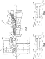
- FIG. 1 schematically illustrates a gas turbine engine 20.
- the gas turbine engine 20 is disclosed herein as a two-spool turbofan that generally incorporates a fan section 22, a compressor section 24, a combustor section 26 and a turbine section 28.
- Alternative engines might include an augmentor section (not shown) among other systems or features.
- the fan section 22 drives air along a bypass flow path B while the compressor section 24 drives air along a core flow path C for compression and communication into the combustor section 26 then expansion through the turbine section 28.
- FIG. 1 schematically illustrates a gas turbine engine 20.
- the gas turbine engine 20 is disclosed herein as a two-spool turbofan that generally incorporates a fan section 22, a compressor section 24, a combustor section 26 and a turbine section 28.
- Alternative engines might include an augmentor section (not shown) among other systems or features.
- the fan section 22 drives air along a bypass flow path B while the compressor section 24 drives air along a core flow path C for compression and communication into the comb
- the engine 20 generally includes a low speed spool 30 and a high speed spool 32 mounted for rotation about an engine central longitudinal axis A relative to an engine static structure 36 via several bearing systems 38. It should be understood that various bearing systems 38 at various locations may alternatively or additionally be provided.
- the low speed spool 30 generally includes an inner shaft 40 that interconnects a fan 42, a low pressure (or first) compressor section 44 and a low pressure (or first) turbine section 46.
- the inner shaft 40 is connected to the fan 42 through a geared architecture 48 to drive the fan 42 at a lower speed than the low speed spool 30.
- the high speed spool 32 includes an outer shaft 50 that interconnects a high pressure (or second) compressor section 52 and high pressure (or second) turbine section 54.
- a combustor 56 is arranged between the high pressure compressor section 52 and the high pressure turbine section 54.
- a mid-turbine frame 57 of the engine static structure 36 is arranged generally between the high pressure turbine section 54 and the low pressure turbine section 46. The mid-turbine frame 57 further supports bearing systems 38 in the turbine section 28.
- the high pressure turbine section experiences higher pressures than the low pressure turbine section.
- a low pressure turbine section is a section that powers a fan 42.
- the low (or first) pressure compressor 44 includes fewer stages than the high (or second) pressure compressor 52, and more narrowly, the low pressure compressor 44 includes three stages and the high pressure compressor 52 includes eight stages ( Figure 1 ). In another example, the low pressure compressor 44 includes four stages and the high pressure compressor 52 includes four stages.
- the high (or second) pressure turbine 54 includes fewer stages than the low (or first) pressure turbine 46, and more narrowly, the low pressure turbine 46 includes five stages, and the high pressure turbine 54 includes two stages. In one example, the low pressure turbine 46 includes three stages, and the high pressure turbine 54 includes two stages.
- the inner shaft 40 and the outer shaft 50 are concentric and rotate via bearing systems 38 about the engine central longitudinal axis A which is collinear with their longitudinal axes.
- the high and low spools can be either co-rotating or counter-rotating.
- the core airflow C is compressed by the low pressure compressor section 44 then the high pressure compressor section 52, mixed and burned with fuel in the combustor 56, then expanded over the high pressure turbine section 54 and low pressure turbine section 46.
- the mid-turbine frame 57 includes airfoils 59 which are in the core airflow path.
- the turbine sections 46, 54 rotationally drive the respective low speed spool 30 and high speed spool 32 in response to the expansion.
- the engine 20 in one example is a high-bypass geared aircraft engine.
- the bypass ratio is the amount of air delivered into bypass path B divided by the amount of air into core path C.
- the engine 20 bypass ratio is greater than about six, and less than about thirty, or more narrowly less than about twenty, with an example embodiment being greater than ten
- the geared architecture 48 is an epicyclic gear train, such as a planetary gear system or other gear system, with a gear reduction ratio of greater than about 2.3 and the low pressure turbine section 46 has a pressure ratio that is greater than about 5.
- the gear reduction ratio is less than about 5.0, or less than about 4.0.
- the engine 20 bypass ratio is greater than about ten
- the fan diameter is significantly larger than that of the low pressure compressor section 44
- the low pressure turbine section 46 has a pressure ratio that is greater than about 5:1.
- the high pressure turbine section may have two or fewer stages.
- the low pressure turbine section 46 in some embodiments, has between 3 and 6 stages.
- the low pressure turbine section 46 pressure ratio is total pressure measured prior to inlet of low pressure turbine section 46 as related to the total pressure at the outlet of the low pressure turbine section 46 prior to an exhaust nozzle.
- the geared architecture 48 may be an epicycle gear train, such as a planetary gear system or other gear system, with a gear reduction ratio of greater than about 2.5:1.
- a planetary gear system may be utilized.
- a star-type gear reduction may be utilized.
- the fan section 22 of the engine 20 is designed for a particular flight condition -- typically cruise at about 0.8 Mach and about 35,000 feet (10,668 m).
- TSFC Thrust Specific Fuel Consumption
- TSFC is the industry standard parameter of the rate of lbm of fuel being burned per hour divided by lbf of thrust the engine produces at that flight condition.
- Low fan pressure ratio is the ratio of total pressure across the fan blade alone, before the fan exit guide vanes.
- the low fan pressure ratio as disclosed herein according to one non-limiting embodiment is less than about 1.45.
- the "Low corrected fan tip speed" as disclosed herein according to one non-limiting embodiment is less than about 1150 ft / second (350.5 m/s). Further, the fan 42 may have 26 or fewer blades.
- An exit area 400 is shown, in Figure 1 and Figure 2 , at the exit location for the high pressure turbine section 54.
- An exit area for the low pressure turbine section is defined at exit 401 for the low pressure turbine section.
- the turbine engine 20 may be counter-rotating. This means that the low pressure turbine section 46 and low pressure compressor section 44 rotate in one direction, while the high pressure spool 32, including high pressure turbine section 54 and high pressure compressor section 52 rotate in an opposed direction.
- the gear reduction 48 may be selected such that the fan 42 rotates in the same direction as the high spool 32 as shown in Figure 2 .
- FIG. 3 Another embodiment is illustrated in Figure 3 .
- the fan rotates in the same direction as the low pressure spool 30.
- the gear reduction 48 may be a planetary gear reduction which would cause the fan 42 to rotate in the same direction.
- PQ Performance quantity
- PQ ltp A lpt ⁇ V lpt 2
- PQ htp A hpt ⁇ V hpt 2
- a lpt is the area of the low pressure turbine section at the exit thereof (e.g., at 401)
- V lpt is the speed of the low pressure turbine section
- a hpt is the area of the high pressure turbine section at the exit thereof (e.g., at 400)
- V hpt is the speed of the high pressure turbine section.
- the areas of the low and high pressure turbine sections are 557.9 in 2 (3599 cm 2 ) and 90.67 in 2 (585 cm 2 ), respectively.
- the speeds of the low and high pressure turbine sections are 10179 rpm and 24346 rpm, respectively.
- the ratio was about 0.5 and in another embodiment the ratio was about 1.5.
- PQ ltp/ PQ hpt ratios in the 0.5 to 1.5 range a very efficient overall gas turbine engine is achieved. More narrowly, PQ ltp/ PQ hpt ratios of above or equal to about 0.8 are more efficient. Even more narrowly, PQ ltp/ PQ hpt ratios above or equal to 1.0 are even more efficient.
- the turbine section can be made much smaller than in the prior art, both in diameter and axial length. In addition, the efficiency of the overall engine is greatly increased.
- the low pressure compressor section is also improved with this arrangement, and behaves more like a high pressure compressor section than a traditional low pressure compressor section. It is more efficient than the prior art, and can provide more work in fewer stages.
- the low pressure compressor section may be made smaller in radius and shorter in length while contributing more toward achieving an overall pressure ratio design target of the engine.
- the speed of the fan can be optimized to provide the greatest overall propulsive efficiency.
- engine 20 is designed at a predetermined design target defined by performance quantities for the low and high pressure turbine sections 46, 54.
- the predetermined design target is defined by pressure ratios of the low pressure and high pressure compressors 44, 52.
- the overall pressure ratio corresponding to the predetermined design target is greater than or equal to about 35:1. That is, after accounting for a pressure rise of the fan 42 in front of the low pressure compressor 44, the pressure of the air entering the low (or first) compressor section 44 should be compressed as much or over 35 times by the time it reaches an outlet of the high (or second) compressor section 52.
- an overall pressure ratio corresponding to the predetermined design target is greater than or equal to about 40:1, or greater than or equal to about 50:1. In some examples, the overall pressure ratio is less than about 70:1, or more narrowly less than about 50:1.
- the predetermined design target is defined at sea level and at a static, full-rated takeoff power condition. In other examples, the predetermined design target is defined at a cruise condition.
- Figure 4 shows an embodiment 200, wherein there is a fan drive turbine 208 driving a shaft 206 to in turn drive a fan rotor 202.
- a gear reduction 204 may be positioned between the fan drive turbine 208 and the fan rotor 202.
- This gear reduction 204 may be structured and operate like the gear reduction disclosed above.
- a compressor rotor 210 is driven by an intermediate pressure turbine 212, and a second stage compressor rotor 214 is driven by a turbine rotor 216.
- a combustion section 218 is positioned intermediate the compressor rotor 214 and the turbine section 216.
- Figure 5 shows yet another embodiment 300 wherein a fan rotor 302 and a first stage compressor 304 rotate at a common speed.
- the gear reduction 306 (which may be structured as disclosed above) is intermediate the compressor rotor 304 and a shaft 308 which is driven by a low pressure turbine section.
Landscapes
- Engineering & Computer Science (AREA)
- Chemical & Material Sciences (AREA)
- Combustion & Propulsion (AREA)
- Mechanical Engineering (AREA)
- General Engineering & Computer Science (AREA)
- Structures Of Non-Positive Displacement Pumps (AREA)
Applications Claiming Priority (1)
| Application Number | Priority Date | Filing Date | Title |
|---|---|---|---|
| US14/935,539 US20160061052A1 (en) | 2012-01-31 | 2015-11-09 | Gas turbine engine with high speed low pressure turbine section |
Publications (1)
| Publication Number | Publication Date |
|---|---|
| EP3165757A1 true EP3165757A1 (fr) | 2017-05-10 |
Family
ID=57286268
Family Applications (1)
| Application Number | Title | Priority Date | Filing Date |
|---|---|---|---|
| EP16197814.3A Withdrawn EP3165757A1 (fr) | 2015-11-09 | 2016-11-08 | Moteur à turbine à gaz à haute vitesse avec section de turbine basse pression |
Country Status (4)
| Country | Link |
|---|---|
| EP (1) | EP3165757A1 (fr) |
| JP (1) | JP2017089646A (fr) |
| BR (1) | BR102016025557A2 (fr) |
| CA (1) | CA2945265A1 (fr) |
Cited By (2)
| Publication number | Priority date | Publication date | Assignee | Title |
|---|---|---|---|---|
| EP3546737A1 (fr) * | 2018-03-30 | 2019-10-02 | United Technologies Corporation | Agencement de compresseur de turbine à gaz |
| US11846238B2 (en) | 2007-09-21 | 2023-12-19 | Rtx Corporation | Gas turbine engine compressor arrangement |
Citations (3)
| Publication number | Priority date | Publication date | Assignee | Title |
|---|---|---|---|---|
| US20120171018A1 (en) * | 2007-09-21 | 2012-07-05 | Hasel Karl L | Gas turbine engine compressor arrangement |
| US20130195648A1 (en) * | 2012-01-31 | 2013-08-01 | Frederick M. Schwarz | Gas turbine engine with high speed low pressure turbine section and bearing support features |
| US20130192200A1 (en) * | 2012-01-31 | 2013-08-01 | United Technologies Corporation | Geared turbofan gas turbine engine architecture |
Family Cites Families (3)
| Publication number | Priority date | Publication date | Assignee | Title |
|---|---|---|---|---|
| CA2850225C (fr) * | 2011-12-27 | 2015-10-13 | United Technologies Corporation | Agencement de compresseur de moteur a turbine a gaz |
| US20130192263A1 (en) * | 2012-01-31 | 2013-08-01 | Gabriel L. Suciu | Gas turbine engine with high speed low pressure turbine section |
| CA2879244C (fr) * | 2014-01-21 | 2018-04-03 | United Technologies Corporation | Rotor de compresseur a faible bruit pour turboreacteur a reducteur de vitesse pour l'entrainement de la soufflante |
-
2016
- 2016-10-12 CA CA2945265A patent/CA2945265A1/fr not_active Abandoned
- 2016-11-01 BR BR102016025557A patent/BR102016025557A2/pt not_active Application Discontinuation
- 2016-11-07 JP JP2016216843A patent/JP2017089646A/ja active Pending
- 2016-11-08 EP EP16197814.3A patent/EP3165757A1/fr not_active Withdrawn
Patent Citations (3)
| Publication number | Priority date | Publication date | Assignee | Title |
|---|---|---|---|---|
| US20120171018A1 (en) * | 2007-09-21 | 2012-07-05 | Hasel Karl L | Gas turbine engine compressor arrangement |
| US20130195648A1 (en) * | 2012-01-31 | 2013-08-01 | Frederick M. Schwarz | Gas turbine engine with high speed low pressure turbine section and bearing support features |
| US20130192200A1 (en) * | 2012-01-31 | 2013-08-01 | United Technologies Corporation | Geared turbofan gas turbine engine architecture |
Cited By (2)
| Publication number | Priority date | Publication date | Assignee | Title |
|---|---|---|---|---|
| US11846238B2 (en) | 2007-09-21 | 2023-12-19 | Rtx Corporation | Gas turbine engine compressor arrangement |
| EP3546737A1 (fr) * | 2018-03-30 | 2019-10-02 | United Technologies Corporation | Agencement de compresseur de turbine à gaz |
Also Published As
| Publication number | Publication date |
|---|---|
| JP2017089646A (ja) | 2017-05-25 |
| CA2945265A1 (fr) | 2017-05-09 |
| BR102016025557A2 (pt) | 2017-05-23 |
Similar Documents
| Publication | Publication Date | Title |
|---|---|---|
| US10240526B2 (en) | Gas turbine engine with high speed low pressure turbine section | |
| US9816442B2 (en) | Gas turbine engine with high speed low pressure turbine section | |
| US9845726B2 (en) | Gas turbine engine with high speed low pressure turbine section | |
| EP3557074A1 (fr) | Moteur à turbine à gaz à haute vitesse avec section de turbine basse pression | |
| CA2856561C (fr) | Turbine a gaz dotee d'une section turbine a basse pression a vitesse elevee | |
| EP3594483A1 (fr) | Moteur à turbine à gaz avec fixation pour section de turbine basse pression | |
| US9611859B2 (en) | Gas turbine engine with high speed low pressure turbine section and bearing support features | |
| US20160061052A1 (en) | Gas turbine engine with high speed low pressure turbine section | |
| EP3708792A1 (fr) | Moteur à turbine à gaz ayant une section basse pression haute vitesse et éléments de support de palier | |
| US20130192265A1 (en) | Gas turbine engine with high speed low pressure turbine section and bearing support features | |
| EP3032084A1 (fr) | Moteur à turbine à gaz à haute vitesse avec section de turbine basse pression | |
| EP3165757A1 (fr) | Moteur à turbine à gaz à haute vitesse avec section de turbine basse pression | |
| EP3165753A1 (fr) | Moteur à turbine à gaz avec fixation pour section de turbine basse pression | |
| EP3165755A1 (fr) | Moteur à turbine à gaz ayant une section basse pression haute vitesse et éléments de support de palier | |
| US20160053631A1 (en) | Gas turbine engine with mount for low pressure turbine section | |
| US20160053679A1 (en) | Gas turbine engine with high speed low pressure turbine section and bearing support features | |
| US20160053634A1 (en) | Gas turbine engine with high speed low pressure turbine section and bearing support features | |
| EP3034849A1 (fr) | Moteur à turbine à gaz à haute vitesse avec section de turbine basse pression | |
| EP3165754A1 (fr) | Moteur à turbine à gaz ayant une section basse pression haute vitesse et éléments de support de palier | |
| EP3163033A1 (fr) | Moteur à turbine à gaz avec section de turbine basse pression à haute vitesse et éléments support de palier | |
| EP3163062A1 (fr) | Moteur à turbine à gaz ayant une section basse pression haute vitesse et éléments de support de palier | |
| US20160047306A1 (en) | Gas turbine engine with high speed low pressure turbine section and bearing support features |
Legal Events
| Date | Code | Title | Description |
|---|---|---|---|
| PUAI | Public reference made under article 153(3) epc to a published international application that has entered the european phase |
Free format text: ORIGINAL CODE: 0009012 |
|
| AK | Designated contracting states |
Kind code of ref document: A1 Designated state(s): AL AT BE BG CH CY CZ DE DK EE ES FI FR GB GR HR HU IE IS IT LI LT LU LV MC MK MT NL NO PL PT RO RS SE SI SK SM TR |
|
| AX | Request for extension of the european patent |
Extension state: BA ME |
|
| STAA | Information on the status of an ep patent application or granted ep patent |
Free format text: STATUS: THE APPLICATION IS DEEMED TO BE WITHDRAWN |
|
| 18D | Application deemed to be withdrawn |
Effective date: 20171111 |