EP3165802B1 - Système de fixation d'un tuyau souple, en particulier d'un tuyau ondulé, à un objet - Google Patents
Système de fixation d'un tuyau souple, en particulier d'un tuyau ondulé, à un objet Download PDFInfo
- Publication number
- EP3165802B1 EP3165802B1 EP16002182.0A EP16002182A EP3165802B1 EP 3165802 B1 EP3165802 B1 EP 3165802B1 EP 16002182 A EP16002182 A EP 16002182A EP 3165802 B1 EP3165802 B1 EP 3165802B1
- Authority
- EP
- European Patent Office
- Prior art keywords
- flexible tube
- tube
- cover
- covering element
- flexible
- Prior art date
- Legal status (The legal status is an assumption and is not a legal conclusion. Google has not performed a legal analysis and makes no representation as to the accuracy of the status listed.)
- Active
Links
Images

Classifications
-
- F—MECHANICAL ENGINEERING; LIGHTING; HEATING; WEAPONS; BLASTING
- F16—ENGINEERING ELEMENTS AND UNITS; GENERAL MEASURES FOR PRODUCING AND MAINTAINING EFFECTIVE FUNCTIONING OF MACHINES OR INSTALLATIONS; THERMAL INSULATION IN GENERAL
- F16L—PIPES; JOINTS OR FITTINGS FOR PIPES; SUPPORTS FOR PIPES, CABLES OR PROTECTIVE TUBING; MEANS FOR THERMAL INSULATION IN GENERAL
- F16L3/00—Supports for pipes, cables or protective tubing, e.g. hangers, holders, clamps, cleats, clips, brackets
- F16L3/14—Hangers in the form of bands or chains
-
- F—MECHANICAL ENGINEERING; LIGHTING; HEATING; WEAPONS; BLASTING
- F16—ENGINEERING ELEMENTS AND UNITS; GENERAL MEASURES FOR PRODUCING AND MAINTAINING EFFECTIVE FUNCTIONING OF MACHINES OR INSTALLATIONS; THERMAL INSULATION IN GENERAL
- F16L—PIPES; JOINTS OR FITTINGS FOR PIPES; SUPPORTS FOR PIPES, CABLES OR PROTECTIVE TUBING; MEANS FOR THERMAL INSULATION IN GENERAL
- F16L3/00—Supports for pipes, cables or protective tubing, e.g. hangers, holders, clamps, cleats, clips, brackets
- F16L3/02—Supports for pipes, cables or protective tubing, e.g. hangers, holders, clamps, cleats, clips, brackets partly surrounding the pipes, cables or protective tubing
- F16L3/04—Supports for pipes, cables or protective tubing, e.g. hangers, holders, clamps, cleats, clips, brackets partly surrounding the pipes, cables or protective tubing and pressing it against a wall or other support
-
- F—MECHANICAL ENGINEERING; LIGHTING; HEATING; WEAPONS; BLASTING
- F16—ENGINEERING ELEMENTS AND UNITS; GENERAL MEASURES FOR PRODUCING AND MAINTAINING EFFECTIVE FUNCTIONING OF MACHINES OR INSTALLATIONS; THERMAL INSULATION IN GENERAL
- F16L—PIPES; JOINTS OR FITTINGS FOR PIPES; SUPPORTS FOR PIPES, CABLES OR PROTECTIVE TUBING; MEANS FOR THERMAL INSULATION IN GENERAL
- F16L11/00—Hoses, i.e. flexible pipes
- F16L11/14—Hoses, i.e. flexible pipes made of rigid material, e.g. metal or hard plastics
- F16L11/15—Hoses, i.e. flexible pipes made of rigid material, e.g. metal or hard plastics corrugated
-
- F—MECHANICAL ENGINEERING; LIGHTING; HEATING; WEAPONS; BLASTING
- F16—ENGINEERING ELEMENTS AND UNITS; GENERAL MEASURES FOR PRODUCING AND MAINTAINING EFFECTIVE FUNCTIONING OF MACHINES OR INSTALLATIONS; THERMAL INSULATION IN GENERAL
- F16L—PIPES; JOINTS OR FITTINGS FOR PIPES; SUPPORTS FOR PIPES, CABLES OR PROTECTIVE TUBING; MEANS FOR THERMAL INSULATION IN GENERAL
- F16L3/00—Supports for pipes, cables or protective tubing, e.g. hangers, holders, clamps, cleats, clips, brackets
- F16L3/24—Supports for pipes, cables or protective tubing, e.g. hangers, holders, clamps, cleats, clips, brackets with special member for attachment to profiled girders
-
- F—MECHANICAL ENGINEERING; LIGHTING; HEATING; WEAPONS; BLASTING
- F16—ENGINEERING ELEMENTS AND UNITS; GENERAL MEASURES FOR PRODUCING AND MAINTAINING EFFECTIVE FUNCTIONING OF MACHINES OR INSTALLATIONS; THERMAL INSULATION IN GENERAL
- F16L—PIPES; JOINTS OR FITTINGS FOR PIPES; SUPPORTS FOR PIPES, CABLES OR PROTECTIVE TUBING; MEANS FOR THERMAL INSULATION IN GENERAL
- F16L57/00—Protection of pipes or objects of similar shape against external or internal damage or wear
- F16L57/06—Protection of pipes or objects of similar shape against external or internal damage or wear against wear
-
- H—ELECTRICITY
- H02—GENERATION; CONVERSION OR DISTRIBUTION OF ELECTRIC POWER
- H02G—INSTALLATION OF ELECTRIC CABLES OR LINES, OR OF COMBINED OPTICAL AND ELECTRIC CABLES OR LINES
- H02G3/00—Installations of electric cables or lines or protective tubing therefor in or on buildings, equivalent structures or vehicles
- H02G3/02—Details
- H02G3/04—Protective tubing or conduits, e.g. cable ladders or cable troughs
- H02G3/0406—Details thereof
-
- H—ELECTRICITY
- H02—GENERATION; CONVERSION OR DISTRIBUTION OF ELECTRIC POWER
- H02G—INSTALLATION OF ELECTRIC CABLES OR LINES, OR OF COMBINED OPTICAL AND ELECTRIC CABLES OR LINES
- H02G3/00—Installations of electric cables or lines or protective tubing therefor in or on buildings, equivalent structures or vehicles
- H02G3/02—Details
- H02G3/04—Protective tubing or conduits, e.g. cable ladders or cable troughs
- H02G3/0462—Tubings, i.e. having a closed section
- H02G3/0468—Corrugated
-
- B—PERFORMING OPERATIONS; TRANSPORTING
- B60—VEHICLES IN GENERAL
- B60R—VEHICLES, VEHICLE FITTINGS, OR VEHICLE PARTS, NOT OTHERWISE PROVIDED FOR
- B60R16/00—Electric or fluid circuits specially adapted for vehicles and not otherwise provided for; Arrangement of elements of electric or fluid circuits specially adapted for vehicles and not otherwise provided for
- B60R16/02—Electric or fluid circuits specially adapted for vehicles and not otherwise provided for; Arrangement of elements of electric or fluid circuits specially adapted for vehicles and not otherwise provided for electric constitutive elements
- B60R16/0207—Wire harnesses
- B60R16/0215—Protecting, fastening and routing means therefor
-
- F—MECHANICAL ENGINEERING; LIGHTING; HEATING; WEAPONS; BLASTING
- F16—ENGINEERING ELEMENTS AND UNITS; GENERAL MEASURES FOR PRODUCING AND MAINTAINING EFFECTIVE FUNCTIONING OF MACHINES OR INSTALLATIONS; THERMAL INSULATION IN GENERAL
- F16L—PIPES; JOINTS OR FITTINGS FOR PIPES; SUPPORTS FOR PIPES, CABLES OR PROTECTIVE TUBING; MEANS FOR THERMAL INSULATION IN GENERAL
- F16L3/00—Supports for pipes, cables or protective tubing, e.g. hangers, holders, clamps, cleats, clips, brackets
- F16L3/08—Supports for pipes, cables or protective tubing, e.g. hangers, holders, clamps, cleats, clips, brackets substantially surrounding the pipe, cable or protective tubing
- F16L3/12—Supports for pipes, cables or protective tubing, e.g. hangers, holders, clamps, cleats, clips, brackets substantially surrounding the pipe, cable or protective tubing comprising a member substantially surrounding the pipe, cable or protective tubing
- F16L3/137—Supports for pipes, cables or protective tubing, e.g. hangers, holders, clamps, cleats, clips, brackets substantially surrounding the pipe, cable or protective tubing comprising a member substantially surrounding the pipe, cable or protective tubing and consisting of a flexible band
-
- F—MECHANICAL ENGINEERING; LIGHTING; HEATING; WEAPONS; BLASTING
- F16—ENGINEERING ELEMENTS AND UNITS; GENERAL MEASURES FOR PRODUCING AND MAINTAINING EFFECTIVE FUNCTIONING OF MACHINES OR INSTALLATIONS; THERMAL INSULATION IN GENERAL
- F16L—PIPES; JOINTS OR FITTINGS FOR PIPES; SUPPORTS FOR PIPES, CABLES OR PROTECTIVE TUBING; MEANS FOR THERMAL INSULATION IN GENERAL
- F16L3/00—Supports for pipes, cables or protective tubing, e.g. hangers, holders, clamps, cleats, clips, brackets
- F16L3/22—Supports for pipes, cables or protective tubing, e.g. hangers, holders, clamps, cleats, clips, brackets specially adapted for supporting a number of parallel pipes at intervals
- F16L3/237—Supports for pipes, cables or protective tubing, e.g. hangers, holders, clamps, cleats, clips, brackets specially adapted for supporting a number of parallel pipes at intervals for two pipes
Definitions
- the invention relates to an arrangement for fastening a flexible tube, in particular a corrugated tube, to an object, in particular to a component of a vehicle.
- corrugated pipes are used inter alia for routing. So it is common to flexible cables, such as. B. for the supply of electrical consumers, such. B. outside marker lights, or used to transmit control signals between ECUs and sensors to summarize branching trunk groups.
- cables such as. B. for the supply of electrical consumers, such. B. outside marker lights, or used to transmit control signals between ECUs and sensors to summarize branching trunk groups.
- cables bundles which are also referred to as harnesses from mechanical influences
- they are often, at least in sections, out in flexible corrugated pipes, which are usually made of plastic and loosely enclose the cable bundle.
- mounting devices are known that allow almost damage-free fastening of wire bundles or pipes.
- the US 2014/0131528 A1 a bracket for attaching a wiring harness to a thin strip, which will avoid strong bruising of the wiring harness.
- the holder in this case has a clasp surrounding the cable bundle, which is first fixed by means of two guide groove on the bar and then firmly clamped by means of a surrounding both the clasp and the strip cable binder.
- a disadvantage of this solution is that the mounting device requires a special type of planar support for mounting.
- the publication DE 10 2010 007 983 A1 discloses a fastening device for fixing a round profile element to a round profile carrier.
- the holder has an S-shaped cross section, whereby two receiving portions are formed, one of which surrounds the round profile carrier and the second round profile element.
- the actual fixation is again by means of a cable tie, which is guided partly on the outer circumference of the fastening means.
- a disadvantage of this construction is that the attachment of the fastening device requires a strong bending of the end portions of the holder.
- it is in the carrier tube in most cases to a solid and thus correspondingly stable object, which actually no anti-crushing is necessary for this area and thus unnecessarily material is consumed in this device.
- the object of the invention is in particular, an arrangement for attaching a flexible tube using a tension band, z. As a cable tie to provide, in which the risk of severe crushing of the flexible tube is avoided.
- an assembly for securing a flexible tube to an article is provided.
- the object to which the flexible tube is fastened may in particular be a component of a vehicle.
- the order includes a flexible tube that is placed on the object.
- the flexible tube may in particular be a corrugated tube.
- the term "flexible tube” should also include flexible tubes, which are usually referred to as hoses due to a comparatively small cross-section.
- the flexible tube may in particular also be a corrugated tube. Due to the flexible tube z. B. be performed at least one electrical line. Due to the flexible tube and a fluid line, for. B. a spray water pipe for a windscreen washer or optical fiber.
- the flexible tube can also be without content.
- the assembly further comprises a cover member for the flexible tube, which is supported on both sides of the flexible tube on the object and the flexible tube at least a portion of an arc-like or bridge-like covers, d. H. under formation of a vault.
- the cover may, for example, in the longitudinal direction of the flexible tube have a U-shaped, an arcuate or a V-shaped cross-section.
- the assembly further includes a tension band passed around an outer surface of the cover member and around a side of the article remote from the flexible tube.
- the strap can be performed, for example, as a locking band, more preferably assverrastendes locking band.
- the strap may be, for example, a cable tie.
- the arrangement according to the invention has the particular advantage that the clamping element is applied and acts directly on the cover element and on the object, but does not touch the flexible tube.
- the clamping element thus generates a flexible force directed to the flexible tube, which acts only indirectly on the cover and the object on the flexible tube.
- the cover serves as crush protection for the flexible tube and acts as anti-crushing element. Excessive squeezing of the corrugated pipe can thus be avoided.
- a fast, uncomplicated mounting option for the flexible tube is provided.
- the attachment approach of the invention can be used at all problematic places on a vehicle where the flexible tube can be crushed, z. As in places where thin corrugated tubes with little degree of filling, z. B. for the electrical supply of outdoor marker lights are used.
- the area where the flexible tube rests on the object preferably forms a generatrix of the flexible tube extending in the longitudinal direction of the flexible tube.
- the outside of the cover is preferably a tube facing away from the outer surface of the cover.
- the inside of the cover preferably forms the flexible tube facing outer surface of the cover, which forms a receiving space for the flexible tube.
- the side of the object facing away from the flexible tube preferably comprises that part of the outer surface of the object on which the tube does not rest.
- a particularly effective crush protection can be achieved if the cover is made of a non-elastic material.
- a particularly advantageous variant provides in this case that the cover is designed as a non-elastic plastic component.
- the cover can also be made of a different material, such. As metal or wood, be formed.
- the cover member has two legs with which the cover is supported on both sides of the flexible tube on the object.
- a recess formed by the inner sides of the legs for receiving the flexible tube is adapted to a diameter of the flexible tube, that the flexible tube rests on both legs.
- the flexible tube is fixed by covering with the cover equal to the object.
- a flexible tube facing the inner contour of the cover is adapted to an outer contour of the flexible tube, so that the cover on a side facing away from the object of the flexible tube on this surface, in particular form-fitting, rests.
- the object is a support tube with a larger diameter than the flexible tube and that the end faces of the cover, with which the cover is supported on the support tube, have a curvature corresponding to the curvature of the support tube.
- an alternative but not claimed aspect provides that the object has a flat footprint on which the flexible tube is placed.
- through holes, in particular slots be provided in the footprint through which the strap is guided.
- the invention further relates to a motor vehicle, in particular a utility vehicle, with an arrangement for securing a flexible tube as described in this document.
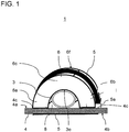
- FIG. 1 shows a schematic cross-sectional view of an arrangement for securing a flexible tube according to an unclaimed aspect.
- the flexible tube 3 is used, for example, for cable bushing in a vehicle and is to be attached to a component 4 with a flat footprint 4a.
- the flexible tube 3 may be designed in a conventional manner, for example as a corrugated tube, wherein the tube material may be made of vulcanized rubber or of a flexible plastic material.
- the flexible tube is first placed on the flat footprint 4a and then covered with a cover 6.
- the cover 6 is designed as a non-elastic plastic component.
- the cover has an arcuate cross-section and has two legs 6a, 6b, which extend away from an upper central shoulder 6c and with which the cover 6 is supported on both sides of the flexible tube 3 on the flat footprint 4a of the article 4.
- the cover 6 thus covers the flexible tube 3 at a longitudinal portion of the flexible tube 3 arcuate. Through the arcuate cross-section or through the inner sides of the legs, a recess 8 for receiving the flexible tube 3 is formed.
- the recess 8 is so matched to the diameter of the flexible tube 3 and adapted to the outer contour of the flexible tube, that the cover 6 at an upper portion of the tube 3 surface, in particular form-fitting, rests.
- This area of the flexible tube 3, opposite to the object 4, is in FIG FIG. 1 denoted by the reference numeral 3e.
- a cable tie 5 is guided around the outer arcuate surface 6f of the cover element 6 and guided around the side 4b of the article 4 facing away from the flexible tube 3.
- slots 4c are correspondingly made in the article 4 for the passage of the cable tie 5.
- the cable tie is clamped by latching on the cable tie head 5a.
- the cable tie 5 thus does not touch the flexible tube directly at any point, but surrounds the cover element 6 and the component 4.
- the cover element 6 transmits the clamping force of the cable tie 5 to the flexible tube 3, but at the same time prevents excessive squeezing of the flexible tube 3.
- FIG. 3 This is schematic and exemplary in FIG. 3 shown.
- Under “I.” is the state of the flexible tube 3 in the normal state, that is shown in the non-assembled state in which no clamping force from the outside acts on the wall of the flexible tube 3.
- the cross section of the flexible tube 3 is circular.
- Under “II.” is the state of the flexible tube 3 in the assembled and tensioned state of FIG. 1 shown.
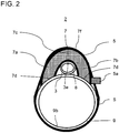
- FIG. 2 shows a cross-sectional view of an arrangement 2 for fixing a flexible tube according to an embodiment of the invention.
- components with the same reference numerals correspond to the components of FIG. 1 and will not be described separately.
- a special feature of this embodiment is that the object on which the flexible tube 3 is to be fastened, a tube, here referred to as a support tube 9, is.
- the serving as Anti-crushing bridge cover 7 is again a component made of non-elastic plastic with an arcuate cross-section.
- the flexible tube 3 is first placed on the support tube 9 and then covered with the cover 7.
- the cover element 7 in turn has two legs 7a, 7b, which extend away from an upper central shoulder 7c and with which the cover 7 is supported on both sides by the flexible tube 3 on the outer wall of the support tube 9.
- the cover member 7 thus covers the flexible tube 3 at a longitudinal portion of the flexible tube 3 like an arc.
- the end faces 7 d of the legs 7 a, 7 b, with which the cover is supported on the support tube 3, have a curvature corresponding to the curvature of the support tube 9.
- the recess 8 is matched to the diameter of the flexible tube 3 or adapted to the outer contour of the flexible tube so that the cover 7 at an upper portion 3e of the tube 3 surface, in particular form-fitting, rests.
- the cable tie 5 is guided around the outer arcuate surface 7f of the cover element 7 and around the side facing away from the flexible tube 3 side 9b of the support tube 9, d. H. around a lower circular arc half of the support tube 9, guided around. Subsequently, the cable tie is clamped by latching on the cable tie head 5a.
- the cable tie 5 at no point directly touches the flexible tube 3, but is guided around the outside around the cover member 7 and the support tube 9.
- the flexible tube 3 can be fastened quickly and securely to the carrier tube 9, without causing excessive squeezing of the flexible tube 3.
Landscapes
- Engineering & Computer Science (AREA)
- General Engineering & Computer Science (AREA)
- Mechanical Engineering (AREA)
- Architecture (AREA)
- Civil Engineering (AREA)
- Structural Engineering (AREA)
- Details Of Indoor Wiring (AREA)
- Clamps And Clips (AREA)
- Supports For Pipes And Cables (AREA)
- Installation Of Indoor Wiring (AREA)
- Rigid Pipes And Flexible Pipes (AREA)
Claims (8)
- Système (2) de fixation d'un tuyau souple (3), en particulier d'un tuyau ondulé, à un tuyau de support (9) de plus grand diamètre que le tuyau souple (3), comprenant:- le tuyau souple (3), qui peut être posé sur le tuyau de support (9),- un élément de recouvrement (7), qui peut s'appuyer sur le tuyau de support (9) de part et d'autre du tuyau souple (3) et qui peut recouvrir en forme d'arc le tuyau souple (3) sur au moins une partie; et- une bande de serrage (5), qui peut être conduite autour d'un côté extérieur (7f) de l'élément de recouvrement (7) et autour d'un côté (9b) du tuyau de support (9) éloigné du tuyau souple (3),caractérisé en ce que les faces frontales (7d) de l'élément de recouvrement (7), avec lesquelles l'élément de recouvrement (7) peut s'appuyer sur le tuyau de support (9), présentent une courbure qui correspond à la courbure du tuyau de support (9).
- Système (2) selon la revendication 1, caractérisé en ce que l'élément de recouvrement présente une section transversale en forme de U, en forme d'arc ou en forme de V pour recouvrir le tuyau souple (3).
- Système selon la revendication 1 ou 2, caractérisé en ce quea) l'élément de recouvrement (7) présente deux branches (7a, 7b), avec lesquelles l'élément de recouvrement (7) s'appuie sur le tuyau de support (9) de part et d'autre du tuyau souple (3); etb) un évidement (8) formé par les côtés intérieurs des branches (7a, 7b) pour loger le tuyau souple (3) est accordé à un diamètre du tuyau souple (3), de telle manière que le tuyau souple (3) s'applique sur les deux branches (7a, 7b).
- Système selon l'une quelconque des revendications précédentes, caractérisé en ce qu'un contour intérieur du recouvrement (7) tourné vers le tuyau souple (3) est adapté à un contour extérieur du tuyau souple (3) de telle manière que le recouvrement (7) s'applique sur un côté du tuyau souple (3) éloigné du tuyau de support (9) en surface, en particulier en complémentarité de forme, sur celui-ci.
- Système selon l'une quelconque des revendications précédentes, caractérisé en ce quea) la bande de serrage (5) est formée par une bande à encliquetage, de préférence par une bande à encliquetage automatique, et/oub) la bande de serrage (5) est un collier serre-câbles.
- Système selon l'une quelconque des revendications précédentes, caractérisé en ce quea) l'élément de recouvrement (7) est fabriqué en un matériau non élastique; et/oub) l'élément de recouvrement (7) est formé par un composant en matière plastique non élastique.
- Système selon l'une quelconque des revendications précédentes, caractérisé en ce quea) le tuyau souple (3) est un tuyau ondulé ou un flexible ondulé; et/oub) au moins un conducteur électrique est conduit dans le tuyau souple (3).
- Véhicule automobile, en particulier véhicule utilitaire, avec un système (2) selon l'une quelconque des revendications précédentes.
Priority Applications (1)
| Application Number | Priority Date | Filing Date | Title |
|---|---|---|---|
| PL16002182T PL3165802T3 (pl) | 2015-11-04 | 2016-10-10 | Układ do mocowania rury elastycznej, w szczególności rury falistej, na przedmiocie |
Applications Claiming Priority (1)
| Application Number | Priority Date | Filing Date | Title |
|---|---|---|---|
| DE102015014226.7A DE102015014226A1 (de) | 2015-11-04 | 2015-11-04 | Anordnung zum Befestigen eines flexiblen Rohres, insbesondere eines Wellrohres, an einem Gegenstand |
Publications (2)
| Publication Number | Publication Date |
|---|---|
| EP3165802A1 EP3165802A1 (fr) | 2017-05-10 |
| EP3165802B1 true EP3165802B1 (fr) | 2018-09-05 |
Family
ID=57130126
Family Applications (1)
| Application Number | Title | Priority Date | Filing Date |
|---|---|---|---|
| EP16002182.0A Active EP3165802B1 (fr) | 2015-11-04 | 2016-10-10 | Système de fixation d'un tuyau souple, en particulier d'un tuyau ondulé, à un objet |
Country Status (8)
| Country | Link |
|---|---|
| US (1) | US10024462B2 (fr) |
| EP (1) | EP3165802B1 (fr) |
| CN (1) | CN107023714B (fr) |
| BR (1) | BR102016024686B1 (fr) |
| DE (1) | DE102015014226A1 (fr) |
| HU (1) | HUE042113T2 (fr) |
| PL (1) | PL3165802T3 (fr) |
| RU (1) | RU2721520C2 (fr) |
Families Citing this family (1)
| Publication number | Priority date | Publication date | Assignee | Title |
|---|---|---|---|---|
| CN110966032B (zh) * | 2019-12-24 | 2024-11-15 | 中国矿业大学徐海学院 | 一种防护功能的煤矿通风用支撑装置 |
Family Cites Families (22)
| Publication number | Priority date | Publication date | Assignee | Title |
|---|---|---|---|---|
| US3243151A (en) * | 1964-04-13 | 1966-03-29 | Richard C Varney | Self-holding pipe strap |
| US3711632A (en) | 1971-12-02 | 1973-01-16 | Gen Motors Corp | End fitting for corrugated conduit |
| US3848839A (en) * | 1972-01-25 | 1974-11-19 | G Tillman | Conduit support clamp |
| US4258515A (en) * | 1977-09-13 | 1981-03-31 | Owen William J | Conduit trunking |
| SU1255799A1 (ru) * | 1984-12-27 | 1986-09-07 | Филиал "Проектэнерговентиляция" Проектно-Конструкторского Бюро Главэнергостроймеханизации | Устройство дл креплени трубопровода к поперечной профильной балке |
| WO1997016666A1 (fr) * | 1995-10-30 | 1997-05-09 | Capro, Inc. | Systeme de fixation de cable de commande |
| US6010099A (en) * | 1997-12-17 | 2000-01-04 | The Whitaker Corporation | Dimple forming clamp used to hold spring jacketed cable |
| US6105907A (en) * | 1998-12-19 | 2000-08-22 | Ta Mfg Co. | Apparatus and method for supporting and/or holding a payload |
| DE60206090T2 (de) * | 2001-03-16 | 2006-06-14 | Yazaki Corp | Kabelbaumanordnung für eine Kraftfahrzeugschiebetür |
| JP3741998B2 (ja) | 2001-11-14 | 2006-02-01 | 矢崎総業株式会社 | コルゲートチューブ用回転保持具 |
| US6729588B2 (en) * | 2001-11-16 | 2004-05-04 | Wilkinson, Iii Joseph | Pipe shoe and method |
| US7722001B2 (en) * | 2005-11-29 | 2010-05-25 | Illinois Tool Works Inc. | Bar clamp assembly |
| US7770848B2 (en) | 2007-11-29 | 2010-08-10 | The Boeing Company | Clamp for securing an object to a structure |
| WO2009132988A1 (fr) * | 2008-04-28 | 2009-11-05 | Thuesen Joergen | Elément de serrage pour fixer un tuyau à une structure de support |
| DE102010007983A1 (de) * | 2010-02-15 | 2011-08-18 | Linde Material Handling GmbH, 63743 | Befestigungsvorrichtung zur Befestigung eines Rundprofilelements an einem Rundprofilträger |
| GB201202883D0 (en) | 2012-02-20 | 2012-04-04 | Airbus Operations Ltd | Clamp block assembly |
| JP5697064B2 (ja) * | 2012-08-27 | 2015-04-08 | 古河As株式会社 | 電磁シールド管 |
| JP5913008B2 (ja) | 2012-09-03 | 2016-04-27 | 矢崎総業株式会社 | ハーネス保護チューブのクランプ構造 |
| GB201220289D0 (en) * | 2012-11-12 | 2012-12-26 | Airbus Operations Ltd | A mount for a cable harness |
| JP5895894B2 (ja) | 2013-04-12 | 2016-03-30 | 住友電装株式会社 | バンドクリップ、バンドクリップ付きワイヤーハーネス及び組み立て品 |
| US9512941B2 (en) * | 2013-07-23 | 2016-12-06 | Hawken Holdings, Llc | Conduit guide apparatus, system, and method |
| FR3016749B1 (fr) | 2014-01-20 | 2016-02-26 | Leoni Wiring Systems France | Dispositif de fixation sur un support d'un organe longiligne formant un faisceau de cables ou une gaine de faisceau de cables pour vehicule automobile |
-
2015
- 2015-11-04 DE DE102015014226.7A patent/DE102015014226A1/de not_active Withdrawn
-
2016
- 2016-10-10 EP EP16002182.0A patent/EP3165802B1/fr active Active
- 2016-10-10 HU HUE16002182A patent/HUE042113T2/hu unknown
- 2016-10-10 PL PL16002182T patent/PL3165802T3/pl unknown
- 2016-10-21 BR BR102016024686-5A patent/BR102016024686B1/pt active IP Right Grant
- 2016-11-02 RU RU2016143097A patent/RU2721520C2/ru active
- 2016-11-03 CN CN201610951245.1A patent/CN107023714B/zh active Active
- 2016-11-04 US US15/343,753 patent/US10024462B2/en active Active
Also Published As
| Publication number | Publication date |
|---|---|
| DE102015014226A1 (de) | 2017-05-04 |
| CN107023714B (zh) | 2020-11-13 |
| PL3165802T3 (pl) | 2019-05-31 |
| EP3165802A1 (fr) | 2017-05-10 |
| RU2016143097A3 (fr) | 2020-03-25 |
| US10024462B2 (en) | 2018-07-17 |
| RU2721520C2 (ru) | 2020-05-19 |
| CN107023714A (zh) | 2017-08-08 |
| BR102016024686A2 (pt) | 2017-05-09 |
| US20170122461A1 (en) | 2017-05-04 |
| RU2016143097A (ru) | 2018-05-07 |
| BR102016024686B1 (pt) | 2022-08-02 |
| HUE042113T2 (hu) | 2019-06-28 |
Similar Documents
| Publication | Publication Date | Title |
|---|---|---|
| EP2647093B1 (fr) | Dispositif de fixation pour la fixation d'un câble | |
| EP1295362B1 (fr) | Bride de fixation electro-conductrice pour cable ou tuyau | |
| DE19828073C1 (de) | Kabelhalter aus Kunststoff für Fahrzeuge | |
| DE102010044665A1 (de) | Befestigungseinrichtung mit einer Ausgleichsschiene zum Toleranzausgleich | |
| DE102010021835A1 (de) | Kabelhaltevorrichtung zum bündelweise Verlegen von Kabeln, insbesondere Koaxialkabeln, in einem Flugzeug | |
| EP3569916B1 (fr) | Dispositif de maintien permettant de fixer une isolation | |
| DE4018905A1 (de) | Kabelzugentlastung | |
| DE10214966C1 (de) | Schelle zum achsparallelen Verbinden eines zylindrischen Temperaturfühlers mit einem Rohr | |
| DE9300184U1 (de) | Kabelendkappe | |
| EP3165802B1 (fr) | Système de fixation d'un tuyau souple, en particulier d'un tuyau ondulé, à un objet | |
| DE102008052332A1 (de) | Baugruppe mit einer Achse und einer auf der Achse angeordneten Feder sowie Vorrichtung zur Befestigung eines Sicherheitsgurtschlosses | |
| DE102009034546A1 (de) | Vorrichtung zum lösbaren Fixieren eines langegestreckten Montageteils an einem Trägerteil | |
| DE102016114734A1 (de) | Leitungshalter für ein Fahrzeug und damit ausgestattete Leitungsanordnung | |
| DE102007046061A1 (de) | Sicherungseinrichtung für eine insbesondere Pressverbindung zwischen einer Schlauchleitung und einer Anschlussarmatur | |
| DE1912219A1 (de) | Vorrichtung zur Befestigung linearer Elemente,wie insbesondere Kabel oder elektrische Leitungen u.dgl. | |
| EP2557644B1 (fr) | Insertion aid for cables | |
| DE102014116468B4 (de) | Befestigungselement und Kabelschacht | |
| DE4406574C1 (de) | Rohrschelle | |
| DE20108139U1 (de) | Klemmvorrichtung | |
| DE102004021667A1 (de) | Schlauchverbindungssystem für einen beheizbaren Schlauch | |
| DE102007000487A1 (de) | Rohrschelle | |
| DE102011106912B4 (de) | Befestigungsclip zur Halterung eines länglichen Bauteils, insbesondere von Rohren, Leitungen oder Kabelbünden in Kraftfahrzeugen | |
| CH684114A5 (de) | Rohrschelle. | |
| DE102007031405A1 (de) | Halteeinrichtung | |
| AT14868U1 (de) | Kabelhalter |
Legal Events
| Date | Code | Title | Description |
|---|---|---|---|
| PUAI | Public reference made under article 153(3) epc to a published international application that has entered the european phase |
Free format text: ORIGINAL CODE: 0009012 |
|
| STAA | Information on the status of an ep patent application or granted ep patent |
Free format text: STATUS: THE APPLICATION HAS BEEN PUBLISHED |
|
| AK | Designated contracting states |
Kind code of ref document: A1 Designated state(s): AL AT BE BG CH CY CZ DE DK EE ES FI FR GB GR HR HU IE IS IT LI LT LU LV MC MK MT NL NO PL PT RO RS SE SI SK SM TR |
|
| AX | Request for extension of the european patent |
Extension state: BA ME |
|
| STAA | Information on the status of an ep patent application or granted ep patent |
Free format text: STATUS: REQUEST FOR EXAMINATION WAS MADE |
|
| 17P | Request for examination filed |
Effective date: 20171108 |
|
| RBV | Designated contracting states (corrected) |
Designated state(s): AL AT BE BG CH CY CZ DE DK EE ES FI FR GB GR HR HU IE IS IT LI LT LU LV MC MK MT NL NO PL PT RO RS SE SI SK SM TR |
|
| GRAP | Despatch of communication of intention to grant a patent |
Free format text: ORIGINAL CODE: EPIDOSNIGR1 |
|
| STAA | Information on the status of an ep patent application or granted ep patent |
Free format text: STATUS: GRANT OF PATENT IS INTENDED |
|
| RIC1 | Information provided on ipc code assigned before grant |
Ipc: B60R 16/02 20060101ALI20180308BHEP Ipc: F16L 3/137 20060101ALN20180308BHEP Ipc: F16L 3/237 20060101ALN20180308BHEP Ipc: F16L 3/04 20060101AFI20180308BHEP |
|
| RIC1 | Information provided on ipc code assigned before grant |
Ipc: F16L 3/04 20060101AFI20180309BHEP Ipc: F16L 3/237 20060101ALN20180309BHEP Ipc: B60R 16/02 20060101ALI20180309BHEP Ipc: F16L 3/137 20060101ALN20180309BHEP |
|
| INTG | Intention to grant announced |
Effective date: 20180410 |
|
| GRAS | Grant fee paid |
Free format text: ORIGINAL CODE: EPIDOSNIGR3 |
|
| GRAA | (expected) grant |
Free format text: ORIGINAL CODE: 0009210 |
|
| STAA | Information on the status of an ep patent application or granted ep patent |
Free format text: STATUS: THE PATENT HAS BEEN GRANTED |
|
| AK | Designated contracting states |
Kind code of ref document: B1 Designated state(s): AL AT BE BG CH CY CZ DE DK EE ES FI FR GB GR HR HU IE IS IT LI LT LU LV MC MK MT NL NO PL PT RO RS SE SI SK SM TR |
|
| REG | Reference to a national code |
Ref country code: GB Ref legal event code: FG4D Free format text: NOT ENGLISH |
|
| REG | Reference to a national code |
Ref country code: CH Ref legal event code: EP |
|
| REG | Reference to a national code |
Ref country code: AT Ref legal event code: REF Ref document number: 1038209 Country of ref document: AT Kind code of ref document: T Effective date: 20180915 |
|
| REG | Reference to a national code |
Ref country code: IE Ref legal event code: FG4D Free format text: LANGUAGE OF EP DOCUMENT: GERMAN |
|
| REG | Reference to a national code |
Ref country code: DE Ref legal event code: R096 Ref document number: 502016001831 Country of ref document: DE |
|
| REG | Reference to a national code |
Ref country code: NL Ref legal event code: FP |
|
| REG | Reference to a national code |
Ref country code: FR Ref legal event code: PLFP Year of fee payment: 3 |
|
| REG | Reference to a national code |
Ref country code: SE Ref legal event code: TRGR |
|
| REG | Reference to a national code |
Ref country code: LT Ref legal event code: MG4D |
|
| PG25 | Lapsed in a contracting state [announced via postgrant information from national office to epo] |
Ref country code: GR Free format text: LAPSE BECAUSE OF FAILURE TO SUBMIT A TRANSLATION OF THE DESCRIPTION OR TO PAY THE FEE WITHIN THE PRESCRIBED TIME-LIMIT Effective date: 20181206 Ref country code: NO Free format text: LAPSE BECAUSE OF FAILURE TO SUBMIT A TRANSLATION OF THE DESCRIPTION OR TO PAY THE FEE WITHIN THE PRESCRIBED TIME-LIMIT Effective date: 20181205 Ref country code: RS Free format text: LAPSE BECAUSE OF FAILURE TO SUBMIT A TRANSLATION OF THE DESCRIPTION OR TO PAY THE FEE WITHIN THE PRESCRIBED TIME-LIMIT Effective date: 20180905 Ref country code: FI Free format text: LAPSE BECAUSE OF FAILURE TO SUBMIT A TRANSLATION OF THE DESCRIPTION OR TO PAY THE FEE WITHIN THE PRESCRIBED TIME-LIMIT Effective date: 20180905 Ref country code: LT Free format text: LAPSE BECAUSE OF FAILURE TO SUBMIT A TRANSLATION OF THE DESCRIPTION OR TO PAY THE FEE WITHIN THE PRESCRIBED TIME-LIMIT Effective date: 20180905 Ref country code: BG Free format text: LAPSE BECAUSE OF FAILURE TO SUBMIT A TRANSLATION OF THE DESCRIPTION OR TO PAY THE FEE WITHIN THE PRESCRIBED TIME-LIMIT Effective date: 20181205 |
|
| PG25 | Lapsed in a contracting state [announced via postgrant information from national office to epo] |
Ref country code: AL Free format text: LAPSE BECAUSE OF FAILURE TO SUBMIT A TRANSLATION OF THE DESCRIPTION OR TO PAY THE FEE WITHIN THE PRESCRIBED TIME-LIMIT Effective date: 20180905 Ref country code: LV Free format text: LAPSE BECAUSE OF FAILURE TO SUBMIT A TRANSLATION OF THE DESCRIPTION OR TO PAY THE FEE WITHIN THE PRESCRIBED TIME-LIMIT Effective date: 20180905 Ref country code: HR Free format text: LAPSE BECAUSE OF FAILURE TO SUBMIT A TRANSLATION OF THE DESCRIPTION OR TO PAY THE FEE WITHIN THE PRESCRIBED TIME-LIMIT Effective date: 20180905 |
|
| PG25 | Lapsed in a contracting state [announced via postgrant information from national office to epo] |
Ref country code: IS Free format text: LAPSE BECAUSE OF FAILURE TO SUBMIT A TRANSLATION OF THE DESCRIPTION OR TO PAY THE FEE WITHIN THE PRESCRIBED TIME-LIMIT Effective date: 20190105 Ref country code: EE Free format text: LAPSE BECAUSE OF FAILURE TO SUBMIT A TRANSLATION OF THE DESCRIPTION OR TO PAY THE FEE WITHIN THE PRESCRIBED TIME-LIMIT Effective date: 20180905 Ref country code: RO Free format text: LAPSE BECAUSE OF FAILURE TO SUBMIT A TRANSLATION OF THE DESCRIPTION OR TO PAY THE FEE WITHIN THE PRESCRIBED TIME-LIMIT Effective date: 20180905 Ref country code: CZ Free format text: LAPSE BECAUSE OF FAILURE TO SUBMIT A TRANSLATION OF THE DESCRIPTION OR TO PAY THE FEE WITHIN THE PRESCRIBED TIME-LIMIT Effective date: 20180905 Ref country code: ES Free format text: LAPSE BECAUSE OF FAILURE TO SUBMIT A TRANSLATION OF THE DESCRIPTION OR TO PAY THE FEE WITHIN THE PRESCRIBED TIME-LIMIT Effective date: 20180905 |
|
| PG25 | Lapsed in a contracting state [announced via postgrant information from national office to epo] |
Ref country code: SK Free format text: LAPSE BECAUSE OF FAILURE TO SUBMIT A TRANSLATION OF THE DESCRIPTION OR TO PAY THE FEE WITHIN THE PRESCRIBED TIME-LIMIT Effective date: 20180905 Ref country code: PT Free format text: LAPSE BECAUSE OF FAILURE TO SUBMIT A TRANSLATION OF THE DESCRIPTION OR TO PAY THE FEE WITHIN THE PRESCRIBED TIME-LIMIT Effective date: 20190105 Ref country code: SM Free format text: LAPSE BECAUSE OF FAILURE TO SUBMIT A TRANSLATION OF THE DESCRIPTION OR TO PAY THE FEE WITHIN THE PRESCRIBED TIME-LIMIT Effective date: 20180905 |
|
| REG | Reference to a national code |
Ref country code: DE Ref legal event code: R097 Ref document number: 502016001831 Country of ref document: DE |
|
| REG | Reference to a national code |
Ref country code: BE Ref legal event code: MM Effective date: 20181031 |
|
| PG25 | Lapsed in a contracting state [announced via postgrant information from national office to epo] |
Ref country code: LU Free format text: LAPSE BECAUSE OF NON-PAYMENT OF DUE FEES Effective date: 20181010 |
|
| REG | Reference to a national code |
Ref country code: HU Ref legal event code: AG4A Ref document number: E042113 Country of ref document: HU |
|
| PLBE | No opposition filed within time limit |
Free format text: ORIGINAL CODE: 0009261 |
|
| STAA | Information on the status of an ep patent application or granted ep patent |
Free format text: STATUS: NO OPPOSITION FILED WITHIN TIME LIMIT |
|
| RAP2 | Party data changed (patent owner data changed or rights of a patent transferred) |
Owner name: MAN TRUCK & BUS SE |
|
| REG | Reference to a national code |
Ref country code: IE Ref legal event code: MM4A |
|
| PG25 | Lapsed in a contracting state [announced via postgrant information from national office to epo] |
Ref country code: DK Free format text: LAPSE BECAUSE OF FAILURE TO SUBMIT A TRANSLATION OF THE DESCRIPTION OR TO PAY THE FEE WITHIN THE PRESCRIBED TIME-LIMIT Effective date: 20180905 Ref country code: MC Free format text: LAPSE BECAUSE OF FAILURE TO SUBMIT A TRANSLATION OF THE DESCRIPTION OR TO PAY THE FEE WITHIN THE PRESCRIBED TIME-LIMIT Effective date: 20180905 |
|
| 26N | No opposition filed |
Effective date: 20190606 |
|
| PG25 | Lapsed in a contracting state [announced via postgrant information from national office to epo] |
Ref country code: BE Free format text: LAPSE BECAUSE OF NON-PAYMENT OF DUE FEES Effective date: 20181031 Ref country code: SI Free format text: LAPSE BECAUSE OF FAILURE TO SUBMIT A TRANSLATION OF THE DESCRIPTION OR TO PAY THE FEE WITHIN THE PRESCRIBED TIME-LIMIT Effective date: 20180905 |
|
| REG | Reference to a national code |
Ref country code: DE Ref legal event code: R081 Ref document number: 502016001831 Country of ref document: DE Owner name: MAN TRUCK & BUS SE, DE Free format text: FORMER OWNER: MAN TRUCK & BUS AG, 80995 MUENCHEN, DE |
|
| PG25 | Lapsed in a contracting state [announced via postgrant information from national office to epo] |
Ref country code: IE Free format text: LAPSE BECAUSE OF NON-PAYMENT OF DUE FEES Effective date: 20181010 |
|
| PG25 | Lapsed in a contracting state [announced via postgrant information from national office to epo] |
Ref country code: MT Free format text: LAPSE BECAUSE OF FAILURE TO SUBMIT A TRANSLATION OF THE DESCRIPTION OR TO PAY THE FEE WITHIN THE PRESCRIBED TIME-LIMIT Effective date: 20180905 |
|
| REG | Reference to a national code |
Ref country code: CH Ref legal event code: PL |
|
| PG25 | Lapsed in a contracting state [announced via postgrant information from national office to epo] |
Ref country code: CY Free format text: LAPSE BECAUSE OF FAILURE TO SUBMIT A TRANSLATION OF THE DESCRIPTION OR TO PAY THE FEE WITHIN THE PRESCRIBED TIME-LIMIT Effective date: 20180905 Ref country code: MK Free format text: LAPSE BECAUSE OF NON-PAYMENT OF DUE FEES Effective date: 20180905 |
|
| PG25 | Lapsed in a contracting state [announced via postgrant information from national office to epo] |
Ref country code: CH Free format text: LAPSE BECAUSE OF NON-PAYMENT OF DUE FEES Effective date: 20191031 Ref country code: LI Free format text: LAPSE BECAUSE OF NON-PAYMENT OF DUE FEES Effective date: 20191031 |
|
| GBPC | Gb: european patent ceased through non-payment of renewal fee |
Effective date: 20201010 |
|
| PG25 | Lapsed in a contracting state [announced via postgrant information from national office to epo] |
Ref country code: GB Free format text: LAPSE BECAUSE OF NON-PAYMENT OF DUE FEES Effective date: 20201010 |
|
| REG | Reference to a national code |
Ref country code: AT Ref legal event code: MM01 Ref document number: 1038209 Country of ref document: AT Kind code of ref document: T Effective date: 20211010 |
|
| PG25 | Lapsed in a contracting state [announced via postgrant information from national office to epo] |
Ref country code: AT Free format text: LAPSE BECAUSE OF NON-PAYMENT OF DUE FEES Effective date: 20211010 |
|
| PGFP | Annual fee paid to national office [announced via postgrant information from national office to epo] |
Ref country code: PL Payment date: 20250929 Year of fee payment: 10 Ref country code: TR Payment date: 20250929 Year of fee payment: 10 |
|
| PGFP | Annual fee paid to national office [announced via postgrant information from national office to epo] |
Ref country code: HU Payment date: 20251009 Year of fee payment: 10 |
|
| PGFP | Annual fee paid to national office [announced via postgrant information from national office to epo] |
Ref country code: NL Payment date: 20251024 Year of fee payment: 10 |
|
| PGFP | Annual fee paid to national office [announced via postgrant information from national office to epo] |
Ref country code: DE Payment date: 20251028 Year of fee payment: 10 |
|
| PGFP | Annual fee paid to national office [announced via postgrant information from national office to epo] |
Ref country code: IT Payment date: 20251022 Year of fee payment: 10 |
|
| PGFP | Annual fee paid to national office [announced via postgrant information from national office to epo] |
Ref country code: FR Payment date: 20251027 Year of fee payment: 10 |
|
| PGFP | Annual fee paid to national office [announced via postgrant information from national office to epo] |
Ref country code: SE Payment date: 20251024 Year of fee payment: 10 |