EP3166207A1 - Elektrisches servolenksystem - Google Patents
Elektrisches servolenksystem Download PDFInfo
- Publication number
- EP3166207A1 EP3166207A1 EP15814171.3A EP15814171A EP3166207A1 EP 3166207 A1 EP3166207 A1 EP 3166207A1 EP 15814171 A EP15814171 A EP 15814171A EP 3166207 A1 EP3166207 A1 EP 3166207A1
- Authority
- EP
- European Patent Office
- Prior art keywords
- rotor
- magnet
- magnets
- magnetic
- motor
- Prior art date
- Legal status (The legal status is an assumption and is not a legal conclusion. Google has not performed a legal analysis and makes no representation as to the accuracy of the status listed.)
- Withdrawn
Links
- 230000004907 flux Effects 0.000 claims description 68
- 238000004804 winding Methods 0.000 claims description 34
- 230000002093 peripheral effect Effects 0.000 claims description 26
- 239000000696 magnetic material Substances 0.000 claims description 22
- 230000002452 interceptive effect Effects 0.000 claims description 2
- 230000005415 magnetization Effects 0.000 description 16
- 230000009467 reduction Effects 0.000 description 15
- 230000008859 change Effects 0.000 description 13
- 238000001514 detection method Methods 0.000 description 11
- 229910000831 Steel Inorganic materials 0.000 description 10
- 239000010959 steel Substances 0.000 description 10
- 230000007246 mechanism Effects 0.000 description 9
- 230000006872 improvement Effects 0.000 description 8
- 230000001965 increasing effect Effects 0.000 description 8
- 229910052779 Neodymium Inorganic materials 0.000 description 7
- QEFYFXOXNSNQGX-UHFFFAOYSA-N neodymium atom Chemical group [Nd] QEFYFXOXNSNQGX-UHFFFAOYSA-N 0.000 description 7
- 230000001629 suppression Effects 0.000 description 7
- 238000001746 injection moulding Methods 0.000 description 5
- 238000010030 laminating Methods 0.000 description 4
- 239000006247 magnetic powder Substances 0.000 description 4
- 238000000034 method Methods 0.000 description 4
- 230000004048 modification Effects 0.000 description 4
- 238000012986 modification Methods 0.000 description 4
- 230000007935 neutral effect Effects 0.000 description 4
- 229920003002 synthetic resin Polymers 0.000 description 4
- 239000000057 synthetic resin Substances 0.000 description 4
- 230000004888 barrier function Effects 0.000 description 3
- 238000009499 grossing Methods 0.000 description 3
- 239000012212 insulator Substances 0.000 description 3
- 230000008569 process Effects 0.000 description 3
- 229910052761 rare earth metal Inorganic materials 0.000 description 3
- 150000002910 rare earth metals Chemical class 0.000 description 3
- RYGMFSIKBFXOCR-UHFFFAOYSA-N Copper Chemical compound [Cu] RYGMFSIKBFXOCR-UHFFFAOYSA-N 0.000 description 2
- XEEYBQQBJWHFJM-UHFFFAOYSA-N Iron Chemical compound [Fe] XEEYBQQBJWHFJM-UHFFFAOYSA-N 0.000 description 2
- 230000008901 benefit Effects 0.000 description 2
- 230000001419 dependent effect Effects 0.000 description 2
- 238000010586 diagram Methods 0.000 description 2
- 239000000463 material Substances 0.000 description 2
- 238000000465 moulding Methods 0.000 description 2
- 230000003313 weakening effect Effects 0.000 description 2
- 239000004593 Epoxy Substances 0.000 description 1
- AWWAHRLLQMQIOC-UHFFFAOYSA-N [Fe].[Sm] Chemical compound [Fe].[Sm] AWWAHRLLQMQIOC-UHFFFAOYSA-N 0.000 description 1
- XAGFODPZIPBFFR-UHFFFAOYSA-N aluminium Chemical compound [Al] XAGFODPZIPBFFR-UHFFFAOYSA-N 0.000 description 1
- 229910052782 aluminium Inorganic materials 0.000 description 1
- 230000015572 biosynthetic process Effects 0.000 description 1
- 238000006243 chemical reaction Methods 0.000 description 1
- 229910052802 copper Inorganic materials 0.000 description 1
- 239000010949 copper Substances 0.000 description 1
- 230000008878 coupling Effects 0.000 description 1
- 238000010168 coupling process Methods 0.000 description 1
- 238000005859 coupling reaction Methods 0.000 description 1
- 230000005347 demagnetization Effects 0.000 description 1
- 230000000694 effects Effects 0.000 description 1
- 230000002708 enhancing effect Effects 0.000 description 1
- 230000001747 exhibiting effect Effects 0.000 description 1
- 238000002474 experimental method Methods 0.000 description 1
- 230000006870 function Effects 0.000 description 1
- 229910052742 iron Inorganic materials 0.000 description 1
- 229910001337 iron nitride Inorganic materials 0.000 description 1
- 238000003475 lamination Methods 0.000 description 1
- 238000012423 maintenance Methods 0.000 description 1
- 230000004044 response Effects 0.000 description 1
- 229910000938 samarium–cobalt magnet Inorganic materials 0.000 description 1
- 238000007493 shaping process Methods 0.000 description 1
- 229910052720 vanadium Inorganic materials 0.000 description 1
- 239000013598 vector Substances 0.000 description 1
- 239000013585 weight reducing agent Substances 0.000 description 1
Images








Classifications
-
- B—PERFORMING OPERATIONS; TRANSPORTING
- B62—LAND VEHICLES FOR TRAVELLING OTHERWISE THAN ON RAILS
- B62D—MOTOR VEHICLES; TRAILERS
- B62D5/00—Power-assisted or power-driven steering
- B62D5/04—Power-assisted or power-driven steering electrical, e.g. using an electric servo-motor connected to, or forming part of, the steering gear
- B62D5/0457—Power-assisted or power-driven steering electrical, e.g. using an electric servo-motor connected to, or forming part of, the steering gear characterised by control features of the drive means as such
- B62D5/046—Controlling the motor
-
- H—ELECTRICITY
- H02—GENERATION; CONVERSION OR DISTRIBUTION OF ELECTRIC POWER
- H02K—DYNAMO-ELECTRIC MACHINES
- H02K29/00—Motors or generators having non-mechanical commutating devices, e.g. discharge tubes or semiconductor devices
- H02K29/03—Motors or generators having non-mechanical commutating devices, e.g. discharge tubes or semiconductor devices with a magnetic circuit specially adapted for avoiding torque ripples or self-starting problems
-
- B—PERFORMING OPERATIONS; TRANSPORTING
- B62—LAND VEHICLES FOR TRAVELLING OTHERWISE THAN ON RAILS
- B62D—MOTOR VEHICLES; TRAILERS
- B62D5/00—Power-assisted or power-driven steering
- B62D5/04—Power-assisted or power-driven steering electrical, e.g. using an electric servo-motor connected to, or forming part of, the steering gear
-
- B—PERFORMING OPERATIONS; TRANSPORTING
- B62—LAND VEHICLES FOR TRAVELLING OTHERWISE THAN ON RAILS
- B62D—MOTOR VEHICLES; TRAILERS
- B62D5/00—Power-assisted or power-driven steering
- B62D5/04—Power-assisted or power-driven steering electrical, e.g. using an electric servo-motor connected to, or forming part of, the steering gear
- B62D5/0409—Electric motor acting on the steering column
-
- B—PERFORMING OPERATIONS; TRANSPORTING
- B62—LAND VEHICLES FOR TRAVELLING OTHERWISE THAN ON RAILS
- B62D—MOTOR VEHICLES; TRAILERS
- B62D5/00—Power-assisted or power-driven steering
- B62D5/04—Power-assisted or power-driven steering electrical, e.g. using an electric servo-motor connected to, or forming part of, the steering gear
- B62D5/0457—Power-assisted or power-driven steering electrical, e.g. using an electric servo-motor connected to, or forming part of, the steering gear characterised by control features of the drive means as such
- B62D5/046—Controlling the motor
- B62D5/0466—Controlling the motor for returning the steering wheel to neutral position
-
- B—PERFORMING OPERATIONS; TRANSPORTING
- B62—LAND VEHICLES FOR TRAVELLING OTHERWISE THAN ON RAILS
- B62D—MOTOR VEHICLES; TRAILERS
- B62D6/00—Arrangements for automatically controlling steering depending on driving conditions sensed and responded to, e.g. control circuits
- B62D6/08—Arrangements for automatically controlling steering depending on driving conditions sensed and responded to, e.g. control circuits responsive only to driver input torque
- B62D6/10—Arrangements for automatically controlling steering depending on driving conditions sensed and responded to, e.g. control circuits responsive only to driver input torque characterised by means for sensing or determining torque
-
- H—ELECTRICITY
- H02—GENERATION; CONVERSION OR DISTRIBUTION OF ELECTRIC POWER
- H02K—DYNAMO-ELECTRIC MACHINES
- H02K1/00—Details of the magnetic circuit
- H02K1/06—Details of the magnetic circuit characterised by the shape, form or construction
- H02K1/12—Stationary parts of the magnetic circuit
- H02K1/14—Stator cores with salient poles
- H02K1/146—Stator cores with salient poles consisting of a generally annular yoke with salient poles
-
- H—ELECTRICITY
- H02—GENERATION; CONVERSION OR DISTRIBUTION OF ELECTRIC POWER
- H02K—DYNAMO-ELECTRIC MACHINES
- H02K1/00—Details of the magnetic circuit
- H02K1/06—Details of the magnetic circuit characterised by the shape, form or construction
- H02K1/22—Rotating parts of the magnetic circuit
- H02K1/24—Rotor cores with salient poles ; Variable reluctance rotors
- H02K1/246—Variable reluctance rotors
-
- H—ELECTRICITY
- H02—GENERATION; CONVERSION OR DISTRIBUTION OF ELECTRIC POWER
- H02K—DYNAMO-ELECTRIC MACHINES
- H02K1/00—Details of the magnetic circuit
- H02K1/06—Details of the magnetic circuit characterised by the shape, form or construction
- H02K1/22—Rotating parts of the magnetic circuit
- H02K1/27—Rotor cores with permanent magnets
- H02K1/2706—Inner rotors
-
- H—ELECTRICITY
- H02—GENERATION; CONVERSION OR DISTRIBUTION OF ELECTRIC POWER
- H02K—DYNAMO-ELECTRIC MACHINES
- H02K1/00—Details of the magnetic circuit
- H02K1/06—Details of the magnetic circuit characterised by the shape, form or construction
- H02K1/22—Rotating parts of the magnetic circuit
- H02K1/27—Rotor cores with permanent magnets
- H02K1/2706—Inner rotors
- H02K1/272—Inner rotors the magnetisation axis of the magnets being perpendicular to the rotor axis
- H02K1/274—Inner rotors the magnetisation axis of the magnets being perpendicular to the rotor axis the rotor consisting of two or more circumferentially positioned magnets
- H02K1/2753—Inner rotors the magnetisation axis of the magnets being perpendicular to the rotor axis the rotor consisting of two or more circumferentially positioned magnets the rotor consisting of magnets or groups of magnets arranged with alternating polarity
- H02K1/276—Magnets embedded in the magnetic core, e.g. interior permanent magnets [IPM]
- H02K1/2766—Magnets embedded in the magnetic core, e.g. interior permanent magnets [IPM] having a flux concentration effect
-
- H—ELECTRICITY
- H02—GENERATION; CONVERSION OR DISTRIBUTION OF ELECTRIC POWER
- H02K—DYNAMO-ELECTRIC MACHINES
- H02K21/00—Synchronous motors having permanent magnets; Synchronous generators having permanent magnets
- H02K21/12—Synchronous motors having permanent magnets; Synchronous generators having permanent magnets with stationary armatures and rotating magnets
- H02K21/14—Synchronous motors having permanent magnets; Synchronous generators having permanent magnets with stationary armatures and rotating magnets with magnets rotating within the armatures
- H02K21/16—Synchronous motors having permanent magnets; Synchronous generators having permanent magnets with stationary armatures and rotating magnets with magnets rotating within the armatures having annular armature cores with salient poles
-
- H—ELECTRICITY
- H02—GENERATION; CONVERSION OR DISTRIBUTION OF ELECTRIC POWER
- H02K—DYNAMO-ELECTRIC MACHINES
- H02K3/00—Details of windings
- H02K3/04—Windings characterised by the conductor shape, form or construction, e.g. with bar conductors
- H02K3/18—Windings for salient poles
-
- H—ELECTRICITY
- H02—GENERATION; CONVERSION OR DISTRIBUTION OF ELECTRIC POWER
- H02K—DYNAMO-ELECTRIC MACHINES
- H02K15/00—Processes or apparatus specially adapted for manufacturing, assembling, maintaining or repairing of dynamo-electric machines
- H02K15/02—Processes or apparatus specially adapted for manufacturing, assembling, maintaining or repairing of dynamo-electric machines of stator or rotor bodies
- H02K15/03—Processes or apparatus specially adapted for manufacturing, assembling, maintaining or repairing of dynamo-electric machines of stator or rotor bodies having permanent magnets
-
- H—ELECTRICITY
- H02—GENERATION; CONVERSION OR DISTRIBUTION OF ELECTRIC POWER
- H02K—DYNAMO-ELECTRIC MACHINES
- H02K2213/00—Specific aspects, not otherwise provided for and not covered by codes H02K2201/00 - H02K2211/00
- H02K2213/03—Machines characterised by numerical values, ranges, mathematical expressions or similar information
Definitions
- the present invention relates to an electric power steering (EPS) system using a brushless motor as a drive source and, more particularly, to an electric power steering system in which returnability, convergence and stability of a steering wheel are improved.
- EPS electric power steering
- Patent Document 1 Jpn. Pat. Appln. Laid-Open Publication No. 2013-81312
- the motor-driven EPS is significantly influenced in terms of returnability, convergence, and stability (straight traveling performance) of a steering wheel by motor friction, motor inertia, or motor loss torque.
- an increase in the motor friction or motor inertia may deteriorate the steering wheel returnability, which in turn may make it difficult for a steering wheel to return to its neutral position.
- the increase in motor friction or motor inertia may deteriorate the convergence and, in this case as well, a steering wheel may hardly return to its neutral position (returning speed is reduced).
- a large loss torque may deteriorate the convergence, and cogging increases with fluctuation in the motor loss torque, which may deteriorate the steering wheel stability.
- an EPS motor When a steering force is assisted, a large assist torque is required during parking or low-speed traveling. Therefore, an EPS motor needs to have a large torque specification so as to ensure a large assist torque.
- the EPS motor is also required to have a high-speed rotation specification. That is, the EPS is required to have a high-torque/high-speed rotation motor and, thus, in general, it has a specification where a high flux magnet and a coil with a large wire diameter are used to reduce the number of turns.
- a motor is connected to a steering shaft through a deceleration mechanism, so that the friction or inertia of the motor is transmitted while being amplified to a steering system. That is, influence of the motor friction or motor inertia becomes large.
- the high-torque/high-speed rotation motor uses a high flux magnet such as a rare earth magnet, so that cogging may increase together with the loss torque or magnetic friction.
- the increase in the loss torque may deteriorate stability of a steering wheel, making the behavior of the steering wheel at the neutral position unstable, which in turn may deteriorate straight traveling stability.
- An electric power steering system uses a brushless motor as a drive source and imparts a steering assist force to a steering shaft of a vehicle.
- the brushless motor includes a stator having a plurality of tooth sections protruding inward in a radial direction of the motor and phase windings wound around the tooth sections in a distributed manner, and a rotor rotatably disposed inside the stator and having a rotor core including a plurality sets of slit groups each having a plurality of curved slits arranged in a layered manner and a magnet embedded in each of the slits.
- the curved slits are each disposed in the rotor with a convex side thereof facing the center of the rotor.
- the magnets are each formed by polar anisotropically magnetizing a bonded magnetic material.
- the rotor is rotated by a magnet torque generated by a magnetic attraction force of the magnets and a reluctance torque based on a difference in inductance between magnetic paths so as to supply the steering assist force.
- the present invention has the following functions:
- the magnets may each be filled and formed by pressure-supplying the bonded magnetic material to the rotor core disposed in a die and polar anisotropically magnetized by a magnet for magnetic field orientation provided in the die.
- the slit groups each have the three curved slits, and three magnets are arranged in a layered manner along the radial direction.
- the three-layered structure has the best balance between a torque and productivity.
- the curved slits may each be formed along a circular arc having its center point outside the rotor. By forming each curved slit into the circular-arc shape and embedding the magnet therein, the magnet can be disposed at a portion having a low magnetic resistance in a q-axis direction, thereby making use of a reluctance torque.
- the magnets may form a first magnetic pole which is N-pole or S-pole and a second magnetic pole which is different in polarity from the first magnetic pole, and assuming that the direction of a magnetic flux formed by the first and second magnetic poles is set as a d-axis, and that the axis that is magnetically orthogonal to the d-axis is set as a q-axis, a plurality of d-axes and q-axes may be provided alternately in the peripheral direction on the rotor.
- the magnets of the first magnetic pole side may be disposed in such a way as to protrude into a region of the second magnetic pole side without interfering with the magnets of the second magnetic pole side.
- the stator may have a bridge part provided in the inner peripheral side of the tooth sections and connecting the inner peripheral side tip portions of the tooth sections.
- the outer periphery of the rotor may be made up of circular arcs each of which has a radius from a different center point for each of the first and second magnetic pole regions, and the center point of the radius may be located eccentrically outward in the radial direction by a predetermined distance from the center of the rotor.
- the eccentric structure of the rotor can reduce a high-frequency component of an induced voltage waveform, thereby reducing a torque ripple.
- the electric power steering system of the present invention by adopting, in a brushless motor as a drive source thereof, an IPM structure in which the magnets are embedded in the plurality of curved slits arranged in a layered state, it is possible to generate a reluctance torque and to suppress a magnet torque.
- By winding the phase winding in a distributed winding pattern it is possible to increase the reluctance torque and to suppress the magnet torque.
- magnet's flux can be suppressed to reduce magnetic friction of the motor to thereby improve returnability, convergence, and stability of a steering wheel. Further, a loss torque due to a magnetic flux can be reduced to thereby improve the convergence.
- the thickness of the magnet can be reduced to thereby reduce a rotor diameter. This reduces inertia to allow improvement in convergence of a steering wheel. Further, the use of the bonded magnet suppresses a variation in assembly of the magnet to reduce cogging. The bonded magnet exhibits less temperature-dependent magnetic flux change, so that a magnetic flux at low temperature can be reduced to thereby suppress a magnet torque.
- the magnetic flux on the rotor surface is made into a sine wave, thereby smoothing a magnetic flux change.
- cogging is reduced to thereby improve returnability, convergence, and stability of a steering wheel.
- the object of the following embodiments is to realize both low friction and low inertia of a brushless motor at the same time as well as low loss torque/low cogging and thus to improve returnability, convergence, and stability of a steering wheel of an EPS.
- the present embodiment improves returnability and convergence of a steering wheel during low-speed traveling and stability of a steering wheel during high-speed traveling by multilaterally and comprehensively reviewing the configuration of an EPS motor to thereby realize an EPS system excellent in traveling stability.
- the steering wheel returnability and stability are greatly influenced by magnetic friction of a motor, and thus a magnet's flux is required to be suppressed. Further, the loss torque having influence on the steering wheel stability also has relation to the magnet's flux.
- a reluctance torque in order to suppress the magnet's flux and have adopted a hybrid type motor that rotates a rotor using a magnet torque and a reluctance torque. Further, for the purpose of increasing the reluctance torque, a distributed winding is used as a winding form.
- an IPM (Interior Permanent Magnet) type brushless motor having a structure in which a magnet is embedded in a rotor is adopted.
- a multilayer IPM rotor having a structure in which curve-shaped (preferably, circular-arc shaped) magnets are arranged in a multilayer is used.
- a bonded magnet is adopted, and it is injection-molded in a rotor core. The use of the bonded magnet reduces a change in temperature of the magnetic flux, so that a magnetic flux density setting that allows for high-temperature demagnetization is relaxed, and the magnet's flux can be suppressed correspondingly.
- Polar anisotropic magnetization is applied to the bonded magnet in the rotor to make a surface magnetic flux into a sine wave. This makes a magnetic flux change smooth to reduce the cogging without skewing (this reduces output torque, causing an increase in magnetic flux). Further, the injection-molding of the bonded magnet suppresses a variation in assembly, which in turn reduces the cogging and a variation thereof.
- the present inventor built an EPS system using a motor provided with:
- FIG. 1 is an explanatory view illustrating a configuration of an electric power steering system according to a first embodiment.
- An electric power steering system 1 (hereinafter, abbreviated as "EPS 1") of FIG. 1 is a column-assist type electric power steering system in which an operation assist force is imparted to a steering shaft 2.
- the EPS 1 uses a brushless motor 3 (hereinafter, abbreviated as "motor 3”) as a power source.
- motor 3 brushless motor
- a steering wheel 4 is attached to the steering shaft 2.
- the steering force of the steering wheel 4 is transmitted to a tie rod 6 through a pinion and a rack shaft (which are not illustrated) provided in a steering gear box 5.
- Wheels 7 are connected to the opposite ends of the tie rod 6, respectively. When the tie rod 6 is actuated with operation of the steering wheel 4, the wheels 7 are tuned left and right through an unillustrated knuckle arm or the like.
- the steering shaft 2 is provided with an assist motor part 8 serving as a steering force assist mechanism.
- the assist motor part 8 is provided with a deceleration mechanism part 9 and a torque sensor 11 together with the motor 3.
- the deceleration mechanism part 9 is provided with a worm and a worm wheel (which are not illustrated).
- the rotation of the motor 3 is transmitted to the steering shaft 2 while being decelerated by the deceleration mechanism part 9.
- the motor 3 and the torque sensor 11 are connected to a controller (ECU) 12.
- the torque sensor 11 for detecting the twist of an unillustrated torsion bar connected to the steering shaft 2 is activated.
- the controller 10 supplies electric power to the motor 3 when necessary according to a detection torque from the torque sensor 11.
- the motor 3 is activated, the rotation of the motor 3 is transmitted to the steering shaft 2 through the deceleration mechanism part 9, whereby a steering assist force is imparted to the steering shaft 2.
- the steering shaft 2 is rotated by the steering assist force from the motor 3 and a manual steering force.
- the rotary motion of the steering shaft 2 is converted into the turning operation of the wheels 7 by coupling between the rack and pinion provided in the steering gear box 5. That is, the rotation of a pinion 5a provided at the leading end of the steering shaft 2 is converted into the linear motion of a rack shaft 5b, which turns the wheels 7.
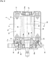
- FIG. 2 is a cross-sectional view of the motor 3
- FIG. 3 is a cross-sectional view of the motor 3 taken along the line A-A of FIG. 2 .
- the motor 3 is an IPM (Interior Permanent Magnet) type brushless motor having a structure in which a magnet is embedded in a rotor, and the rotor is rotated by a magnet torque and a reluctance torque.
- the IPM motor has a smaller magnetic friction than an SPM motor and thus can suppress a viscosity torque, thereby achieving stable convergence of a steering wheel.
- the motor 3 is an inner rotor type brushless motor including a stator 13 on an outer side thereof and a rotor 14 on an inner side thereof.
- the stator 13 is fixed to the inside of a bottomed cylindrical motor casing 15.
- the rotor 14 is rotatably fitted in the casing 15.
- the casing 15 is made of a magnetic material such as iron and is formed into a bottomed cylindrical shape.
- the casing 15 has an opening part which is fitted with an aluminum die cast bracket 16 by an unillustrated fixing screw.
- the stator 13 is constituted of a stator core 12, stator coils 17 (phase winding, hereinafter, referred to as "coils 17") and a bus bar unit (terminal unit) 18.
- the bus bar unit 18 is fitted to the stator core 12 and electrically connected to the coils 17.
- the coils 17 are wound in tooth sections 19 of the stator core 12 in a distributed winding pattern.
- Motor coil winding forms include the distributed winding and a concentrated winding. In this example, the distributed winding is adopted.
- a magnetic flux concentrated portion inevitably occurs in a stator core.
- magnetic saturation occurs to increase a magnetic resistance, making it difficult for a magnetic flux to flow there.
- the stator core 12 is formed by laminating a number of steel sheet materials (e.g., electromagnetic steel sheet).
- a plurality of (24, in this example) tooth sections 19 are formed so as to protrude inward in the radial direction of the motor 3.
- a slot 22 is formed between the adjacent tooth sections 19.
- the number of the tooth sections 19 is 24 and it has a 24-slot configuration.
- the slot 22 houses inside thereof the coils 17.
- the stator core 12 is fitted with a synthetic resin insulator 23.
- the coils 17 are wound at the outside of the insulator 23.
- the bus bar unit 18 is fitted to one end side of the stator core 12.
- the bus bar unit 18 has a synthetic resin main body formed into an annular shape. Inside the main body, a copper bus bar 24 is insert-molded. A plurality of bus bar terminals 25 are formed around the bus bar unit 18 so as to protrude in the radial direction.
- an end portion 17a of each of the coils 17 drawn from the stator core 12 is welded and electrically connected to each of the bus bar terminals 25.
- the bus bars are provided as many as the number (in this example, four bas bars (three for U-, V-, and W-phases, and one for connecting the three phases) are provided) of phases of the motor 3.
- the coils 17 are electrically connected to the bus bar terminals 25 corresponding to the respective phases.
- phase currents U, V, and W
- the stator core 12 is fitted with the bus bar unit 18 and then press-fitted and fixed inside the casing 15.
- FIG. 5 is an explanatory view illustrating a configuration of the rotor 14.
- a rotary shaft 27 of the rotor 14 is rotatably axially supported by bearings 29a and 29b.
- the bearings 29a and 29b are fixed to the bottom center of the casing 15 and the center portion of the bracket 16, respectively.
- the rotary shaft 27 is fitted, by a fixing means such as press-fitting, with a cylindrical rotor core 28 and a rotor (resolver rotor) 34a of a resolver 34 serving as a rotation angle detection means.
- a stator (resolver stator) 34b of the resolver 34 is housed in a synthetic resin resolver bracket 34c.
- the resolver bracket 34c is fixed to the inside of the bracket 16 by a fitting screw 35.
- the rotary shaft 27 is connected to a worm shaft of the deceleration mechanism part 9 by an unillustrated joint member.
- a worm is formed on the worm shaft.
- the worm shaft meshes with a worm wheel fixed to the steering shaft 2.
- the rotor core 28 is also formed by laminating a number of disk-shaped electromagnetic steel sheets.
- Slit groups 31 are formed so as to be bent in a circular arc (arched shape).
- the slit groups 31 are formed along the circular arc having its center at a virtual point (not illustrated) set outside the outer periphery of the rotor 14.
- Three slits are arranged as one slit group in a layered state in the radial direction with convex sides thereof facing the center side of the rotor 14. That is, one set of slit group 31 is constituted of the outermost first slit 31a, the intermediate second slit 31b, and the innermost third slit 31c.
- the slit groups 31 are each filled with a bonded magnet, and thus rotor magnet 32 are formed.
- the rotor magnets 32 are installed inside the rotor 14, whereby the motor 3 becomes an IPM type brushless motor.
- an anisotropic neodymium bonded magnetic material or the like is used as the bonded magnet.
- the neodymium bonded magnetic material is a material obtained by mixing magnetic powder of a rare-earth magnet such as a neodymium magnetic material with a synthetic resin such as epoxy.
- the bonded magnetic material is filled in each slit group 31 by injection molding, followed by predetermined magnetization, whereby shaping of the bonded magnetic material is accomplished.
- magnetic pole parts 33 each constituted of laminated magnets are formed by the rotor magnets 32 in the slit groups 31.
- a rotor magnet 32s whose outer peripheral side is magnetized as S-pole and a rotor magnet 32n whose outer peripheral side is magnetized as N-pole are provided.
- Two magnetic pole parts magnetized as S-pole and two magnetic pole parts magnetized as N-pole (four magnetic pole parts in total) are alternately arranged along the peripheral direction of the rotor 14.
- the motor 3 has a 4-pole 24-slot (4P24S) structure.
- Each magnetic pole part 33 has three rotor magnets 32 arranged in a layered state along the radial direction.
- a d-axis which is a direction of the magnetic flux formed by each of the magnetic poles and a q-axis which is magnetically orthogonal to the d-axis are formed by each of the magnetic pole parts 33.
- a plurality of the d- and q-axes are alternately arranged in the peripheral direction on the rotor 14.
- the circular arc-shaped slit groups 31 are provided.
- the slit groups 31 are each filled with the rotor magnet 32.
- the rotor 14 is formed in such a way as to make it easier for the q-axis magnetic flux to pass and to increase an inductance Lq.
- Lq inductance
- Ld inductance
- the difference between Lq and Ld is larger when the number of magnet layers is three than when it is one or two, no significant difference is observed when the number of layers is greater than or equal to three.
- the magnets are formed as three layers in the rotor 14 for effectively increasing the reluctance torque.
- the reluctance torque can be efficiently generated. Further, by arranging the rotor magnets 32 in a multilayer, the reluctance torque can be made larger. Further, the coils 17 are wound in a distributed winding pattern to make it difficult for magnetic saturation to occur, so that the magnetic resistance of the q-axis magnetic flux can be suppressed, resulting in an increase in the reluctance torque.
- the increase in the reluctance torque can reduce a magnet torque correspondingly to allow magnetic friction and loss torque of the motor, whereby returnability, convergence, and stability of the steering wheel can be improved.
- the thickness of the magnet needs to be made smaller.
- a gap air layer
- a magnet resistance is increased, and self-demagnetization easily occurs.
- backlash occurs due to existence of the gap to cause a variation in performance.
- the rotor magnets 32 are formed by injection-molding of the bonded magnets.
- the gap is not generated, and thus, the variation in performance due to backlash is not also generated.
- FIG. 7 is a schematic explanatory view illustrating the molding process of the rotor 14.
- the rotor 14 is formed using a magnetic field orientation die 37 provided with a plurality of magnets 36 for magnetic field orientation.
- a rare-earth magnet such as a samarium cobalt magnet is used as the magnets 36 for magnetic field orientation.
- the rotor core 28 is housed and disposed in a cavity part 38 formed inside the magnets 36 for magnetic field orientation.
- An upper die 39 connected to an unillustrated nozzle of an injection molding machine is placed on the cavity part 38.
- the upper die 39 has a plurality of runners 41 and a sprue 42 connected with one ends of the respective runners 41.
- the runners 41 serve as flow paths for supplying a molten bonded magnet to the plurality sets of slit groups 31.
- Each of the runners 41 are branched at the other end so as to correspond to slits 31a to 31c of each of the plurality sets of slit groups 31.
- a connection part (opening part) between the slits 31a to 31c of each of the plurality sets of slit groups 31 and the runners 41 serve as a plurality of gates 43.
- the rotor core 28 for which a lamination process has been completed is housed in the cavity part 38 of the magnetic field orientation die 37.
- the upper die 39 is placed on the rotor core 28, and the slit groups 31 of the rotor core 28 and the gates 43 are connected to each other.
- a molten bonded magnetic material is injected to the sprue 42 from an unillustrated nozzle of an injection molding machine.
- the bonded magnetic material supplied by pressurization to the sprue 42 flows inside the each slits 31a to 31c of the slit groups 31 of the rotor core 28 from the runners 41 through the gates 43.
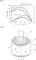
- FIG. 8 is an explanatory view illustrating a result obtained by comparing the relationship between a temperature and a motor toque between the bonded magnet and a sintered magnet.
- the torque is reduced by approximately 10%.
- the torque is reduced by almost half of the value obtained in the neodymium sintered magnet.
- a magnet having a lower flux density than the sintered magnet can be used in order to obtain the same target torque of 100°C.
- loss torque and cogging are reduced due to the reduced magnetic flux density. This results in improvement in stability of the steering wheel to make the behavior of the steering wheel at the neutral position stable, which in turn improves straight traveling stability.
- FIG. 9A is an explanatory view illustrating a magnetized state of a ring magnet subjected to the polar anisotropic magnetization
- FIG. 9B is an explanatory view illustrating a surface magnetic flux density in the polar anisotropic magnetized ring magnet
- FIG. 9C is an explanatory view illustrating a magnetized state of the rotor magnet 32.
- the magnets of respective layers are magnetized in such a way that magnetization vectors are directed to the center positioned inside the circular arc as illustrated in FIG. 9C , so that a peak value of the surface magnetic flux is increased. Further, as illustrated in FIG. 9B , the surface magnetic flux density becomes a sine wave.
- a surface magnetic flux density waveform after magnetization has a high peak value and brought close to a sine wave. Therefore, when such a rotor magnet is used in the rotor 14, a motor having a low cogging torque can be achieved without skewing.
- stability of the steering wheel is improved, thereby enhancing straight traveling stability during high-speed traveling.
- the bonded magnetic material in the slit groups 31 is magnetized by the magnets 36 for magnetic field orientation. That is, the rotor magnets 32 are shaped while being magnetized by the magnets 36 for magnetic field orientation. In the magnetic field orientation die 37, the magnets 32 are magnetized up to a magnetization percentage of about 80% of a full magnetization state by the magnets 36 for magnetic field orientation. Then, the rotor 14 is subjected to full magnetization by a magnetizing machine after the bonded magnetic material is filled and shaped. However, when the 80% magnetization state is sufficient for practical use, the additional magnetization using the magnetizing machine can be omitted.
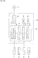
- FIG. 10 is a block diagram illustrating a configuration of the controller 10 of the EPS 1.
- the EPS 1 is drive-controlled by the controller 10.
- the controller 10 includes a current command section 50 that controls an amount of current to be supplied to the motor 3, a RAM 59 and a ROM 60 that store control data.
- the current command section 50 is connected with the torque sensor 11, a vehicle speed sensor 51, the resolver 34, and a current sensor 52.
- the current command section 50 determines an amount of current to be supplied to the motor 3 on the basis of detection values from the respective sensors and appropriately controls the EPS 1.
- the torque sensor 11 detects, accompanying the operation of the steering wheel 4, the twisting of an unillustrated torsion bar connected to the steering shaft 2 to thereby detect a torque value which is a load value of the motor 3.
- the detection value of the torque sensor 11 is input to the current command section 50 as motor load information.
- the vehicle speed sensor 51 detects a travel speed of a vehicle on which the EPS 1 is mounted.
- the detection value of the vehicle speed sensor 51 is input to the current command section 50 as vehicle speed information.
- the resolver 34 detects a rotation position of the rotor 14.
- the rotor rotation position is successively input to the current command section 50 as rotor rotation position information.
- the current command section 50 also calculates a motor rotational speed from the rotor rotation position information.
- the current sensor 52 detects a current value presently supplied to the motor 3 and outputs the detected current value to the current command section 50.
- the current command section 50 includes a basic current calculation section 53 that performs computation based on the above detection values to calculate a basic current amount to be supplied to the motor 3.
- the basic current calculation section 53 calculates the basic current amount by referring to a basic current map 54 on the basis of the detection values from the torque sensor 11 and the vehicle speed sensor 51.
- the basic current calculation section 53 sets the amount of current to be supplied to the motor so that an assist force according to a steering torque is output in accordance with a vehicle speed.
- the current command section 50 further includes a differential compensation control section 55.
- the differential compensation control section 55 calculates a current compensation value for correcting the basic current amount on the basis of the detection values from the torque sensor 11 and the vehicle speed sensor 51.
- the current compensation value corrects the motor supply current in accordance with fluctuation in the steering torque to suppress fluctuation in the steering force, thereby improving a steering feeling.
- the current command section 50 further includes a steering wheel returning control section 56 and a convergence control section 57.
- the control sections 56 and 57 appropriately correct the basic current amount on the basis of the detection values from the vehicle speed sensor 51 and the resolver 34 so as to improve returnability and convergence of the steering wheel.
- the steering wheel returning control section 56 makes current flow in an assist direction so as to assist returning of the steering wheel during low-speed traveling, thereby improving returnability of the steering wheel by a self-aligning torque.
- the convergence control section 57 makes motor current flow in a direction opposite to a steering wheel rotation direction to improve convergence and stability of the steering wheel when hands are off the steering wheel and adjusts the difference between a steering reaction force in a turning state and that in a returning state.
- a target current calculation section 58 is provided at the rear stage of the basic current calculation section 53 and the differential compensation control section 55.
- the target current calculation section 58 calculates and determines an amount of current to be supplied to the motor 3.
- the target current calculation section 58 adds, to the basic current amount calculated by the basic current calculation section 53, the current compensation value calculated by the differential compensation control section 55 and the settings made by the steering wheel returning control section 56 and the convergence control section 57 to thereby finally determine the current amount.
- the target current calculation section 58 receives a present current value of the motor 3 from the current sensor 52.
- the target current calculation section 58 feedback-controls the motor 3 on the basis of the present current value.
- FIG. 11 is an explanatory view illustrating a control mode for controlling the EPS 1 using the controller 10.
- the controller 10 performs maximum torque control during parking/low-speed traveling so as to make the motor 3 as "high torque motor”.
- the motor 3 adopts the "distributed winding stator", the "circular-arc shaped multilayer magnet rotor", and the “polar anisotropic bonded magnet” and can thereby realize low friction and low inertia and suppress loss torque while exhibiting high torque.
- returnability and convergence of the steering wheel during parking/low-speed traveling are improved, making it possible to perform garaging operation easily and comfortably.
- the controller 10 performs maximum rotation speed control so as to make the motor 3 as "high-speed rotation motor".
- an assist force can be promptly imparted with a high rotational speed also at a wheel turning operation during high-speed traveling.
- the motor 3 realizes low friction and low inertia and suppresses loss torque and cogging.
- high responsibility is exhibited during high-speed traveling and, at the same time, stability of the steering wheel is improved to improve straight traveling stability, thereby enabling stable high-speed traveling.
- the controller 10 performs optimum control according to the torque and the vehicle speed. That is, the controller 10 drives the motor 3 in a control mode in which the maximum torque control and the maximum rotation speed control are mixed on the basis of the detection values from the torque sensor 11 and the vehicle speed sensor 51. This control mode is reflected in the basic current map 54.
- the controller 10 imparts an assist force appropriate for conditions to the EPS system according to the torque and the vehicle speed while referring to the basic current map 54.
- the EPS 1 according to the present invention has the following advantages.
- the diameter of the rotor can be reduced to allow inertia reduction.
- the inertia reduction allows the rotor to be rotated lightly, thereby improving convergence of the steering wheel.
- the reduction in the cogging improves returnability, convergence, and stability of the steering wheel.
- FIG. 12 is a cross-sectional view of a brushless motor 61 used in the EPS system according to the second embodiment of the present invention.
- a motor 61 is used as a drive source for the EPS system as illustrated in FIG. 1 .
- the motor 61 is an inner rotor type brushless motor including a stator 62 on an outer side thereof and a rotor 63 on an inner side thereof.
- the stator 62 has a stator core 64 and a stator coil 65 (hereinafter, referred to as "coil 65").
- the stator core 64 is constituted of a cylindrical outer stator 66 and an inner stator 67 fitted to the inner peripheral side of the outer stator 66.
- the inner stator 67 is constituted of radially-formed 24 tooth sections 68 and a bridge part 69 connecting the inner peripheral sides of the tooth sections 68.
- a slot 71 is formed between the adjacent tooth sections 68.
- a width W of the bridge part 69 in the radial direction is set within a range t (thickness of one steel sheet constituting the stator core 64) ⁇ W ⁇ 1.5 mm.
- the inner peripheral sides of the tooth sections 68 are connected by the bridge part 69. Accordingly, unlike a typical motor, a coil cannot be wound around the tooth section with the use of slits on the tooth tip sides.
- the stator 62 is divided into the outer stator 66 and the inner stator 67, and the tooth section outer peripheral sides of the inner stator 67 are made open. This configuration enables formation of a coil 65, by winding a copper wire around the tooth sections 68. After the coil 65 is wound around in a distributed winding pattern, the tooth sections 68 are mounted on the inner peripheral side of the outer stator 66 (fitting and fixing). The distributed winding can keep the leak of magnetic flux in the bridge part 69 lower than that of the concentrated winding and can have a larger maximum torque than the concentrated winding.
- the width W of the bridge part 69 is preferably set to equal to or larger than the thickness of one steel sheet constituting the stator core 64 in order to reduce cogging.
- the width W is preferably equal to or smaller than 1.5 mm.
- FIG. 14 is an explanatory view illustrating a configuration of a fitting/fixing part between the outer stator 66 and the inner stator 67.
- the motor 61 has the 24 tooth sections 68.
- Each tooth section 68 is fitted/fixed at its outer peripheral side to a tooth fitting groove (concave part) 16 formed in the inner peripheral surface of the outer stator 66.
- the outer stator 66 has a dovetail tooth fitting groove 72 having a V-shape cross section.
- the tooth fitting groove 72 is formed so as to extend in the axial direction over the entire length of the outer stator 66.
- the tooth section 68 has, at its outer peripheral side, a tenon fitting part 73 whose outer end side is expanded.
- a rotor core 74 constituting the rotor 63 is also formed by laminating a number of disk-shaped electromagnetic steel sheets.
- a plurality of circular-arc shaped slits 75 are formed in the steel sheets constituting the rotor core 74.
- the plurality sets of slits 75 are provided, with q-axis, which is perpendicular to a rotary shaft 76, as a boundary.
- the slits 75 are provided in the motor 61.
- a magnet 77 is embedded in each slit 75.
- the slits 75 are disposed in a circular-arc shape around imaginary points (described later; centers Os and On of circular arcs of S- and N-pole magnets 77n and 77s), which are set outside the outer periphery of the rotor 63 on d-axis.
- Cavity parts 75a functioning as a flux barrier for making magnetic resistance of the rotor 63 vary along the rotational direction are formed in the steel sheets constituting the rotor core 74.
- a segment magnet is used as the magnet 77 in the motor 61, a bonded magnet may be used.
- FIG. 15 is an explanatory view illustrating the rotor 63.
- magnets 77s as the plurality of magnets 77, magnets 77s (77s1, 77s2) whose outer peripheral sides serve as S-poles and magnets 77n (77n1, 77n2) whose outer peripheral sides serve as N-poles are provided.
- the rotor 63 has a 4-pole structure, and the motor 61 is so formed as to have a 4-pole 24-slot structure.
- the S-pole magnets 77s1 and 77s2 and N-pole magnets 77n1 and 77n2 are disposed asymmetrically about the center line (magnet asymmetric arrangement).
- the rotor 63 is shaped in such a way as to have an eccentric outer periphery (rotor eccentricity).
- the asymmetrical setting of the magnets reduces the torque ripple.
- the asymmetrical setting in the rotor 63 has the following features:
- a space 79 is provided between the S-pole magnet 77s and its adjacent N-pole magnet 77n.
- a magnet that protrudes into an adjacent zone-side region may be of either S-pole or N-pole. What is shown here is the case where the S-pole magnet 77s has lapped over into the N-pole zone.
- the number of times cogging occurs is equal to a least common multiple of the poles and slots. Accordingly, in the case of a 4-pole 24-slot motor, cogging occurs for 24 peaks per rotation of the motor. In order to reduce the cogging, some methods are available, such as application of skewing. In this case, the problem is that the torque is lowered due to leakage flux. In the case of the motor 61, the rotor 63 is formed into an asymmetrical shape in line with (a) to (c). Therefore, the cogging is reduced as attraction forces generated between the rotor and the stator in respective poles are cancelled.
- the output torque of the motor 61 is a combination of reluctance torque and magnet torque.
- the ripple of the reluctance torque becomes larger.
- the rotor is asymmetrical. Therefore, the reluctance torque that is generated in the S-pole zones S1, S2 and the reluctance torque that is generated in the N-pole zones N1, N2 are cancelled, leading to a reduction in the torque ripple.
- the magnet torque in the case of a symmetric rotor, an induced voltage waveform deforms as high-frequency components are superimposed on the magnetic flux, resulting in an increase in the torque ripple.
- an asymmetric rotor high-frequency components are cancelled, an induced voltage waveform is made into a sine wave, and a torque ripple of a magnet torque is reduced.
- FIG. 16 is an explanatory view illustrating an eccentric configuration of the rotor 63.
- the rotor outer shape is exaggerated.
- the outer periphery of the rotor 63 is not a uniform circumference of a circle around the point Or.
- the outer periphery of the rotor 63 is made up of circular arcs each of which has a radius from a different center point for each of the four pole zones S1, S2, N1, and N2.
- the outer peripheries of the respective pole zones S1, S2, N1, and N2 are connected together at a boundary point P of each pole zone.
- the outer periphery of each pole zone is formed as a circular arc with a radius of Rec from eccentric point Oec.
- the eccentric point Oec is an eccentric distance Lec away from the rotor center point Or toward a radial-direction outer side.
- the eccentric point Oec is located on a line segment that is tilted at 45 degrees to the center lines M1 and M2.
- the radius Rec is smaller than a distance Rmax between an outermost position Q of the rotor 63 and the rotor center point Or.
- the motor 61 can reduce both the ripples of the reluctance torque and the magnet torque, and can reduce the cogging.
- the use of motor 61 for the EPS system can improve convergence and stability of the steering wheel.
- the motor has a configuration in which three rotor magnets (slit group) are arranged in a layered manner in the rotor and, as described above, placing three magnets is suitable in terms of balance; however, the number of magnets to be arranged in a layered manner is not limited to three, and two or four or more magnets may be arranged in a layered manner.
- the neodymium bonded magnet is exemplified as a bonded magnet, other bonded magnets such as a samarium iron nitride bonded magnet may be used.
- the cavity part functioning as a flux barrier is provided in the steel sheets constituting the rotor core
- a configuration like the first embodiment, in which no cavity part is provided may be adopted.
- a non-magnetic material may be disposed in the cavity part.
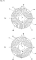
- a "curved" means not only circular-arc form but also includes a magnet 81 illustrated as a modification in FIG. 17A having a trapezoidal shape (upper base and two oblique sides of an isosceles trapezoid). Further, as illustrated in FIG. 17B , a polygonal line shaped magnet 82 approximate to a circular arc is included in the curved magnet.
- the resolver 34 is exemplified as a means for detecting the rotation position of the rotor 14, the means for detecting the rotor rotation position is not limited to this.
- a combination of a rotor magnet and a hall sensor may be used.
- the "magnet asymmetrical arrangement" and "rotor eccentricity" described in the second embodiment may be separately applied.
- FIGS. 17A and 17B when the bonded magnetic material is injection-molded into the slit groups of the rotor core 74, the magnetic material can sufficiently be filled in corner portions of each slit.
- the cavity part functioning as a flux barrier may be provided at end portions of each slit.
- the motor 3 is mounted to the steering shaft 2, the motor 3 may be applied to a structure for assisting the pinion 5a in the steering gear box 5 or an EPS system for directly assisting the rack shaft 5b.
Landscapes
- Engineering & Computer Science (AREA)
- Power Engineering (AREA)
- Chemical & Material Sciences (AREA)
- Combustion & Propulsion (AREA)
- Transportation (AREA)
- Mechanical Engineering (AREA)
- Power Steering Mechanism (AREA)
- Iron Core Of Rotating Electric Machines (AREA)
- Permanent Field Magnets Of Synchronous Machinery (AREA)
Applications Claiming Priority (2)
| Application Number | Priority Date | Filing Date | Title |
|---|---|---|---|
| JP2014136468A JP2016015819A (ja) | 2014-07-02 | 2014-07-02 | 電動パワーステアリングシステム |
| PCT/JP2015/063197 WO2016002334A1 (ja) | 2014-07-02 | 2015-05-07 | 電動パワーステアリングシステム |
Publications (2)
| Publication Number | Publication Date |
|---|---|
| EP3166207A1 true EP3166207A1 (de) | 2017-05-10 |
| EP3166207A4 EP3166207A4 (de) | 2018-02-21 |
Family
ID=55018891
Family Applications (1)
| Application Number | Title | Priority Date | Filing Date |
|---|---|---|---|
| EP15814171.3A Withdrawn EP3166207A4 (de) | 2014-07-02 | 2015-05-07 | Elektrisches servolenksystem |
Country Status (4)
| Country | Link |
|---|---|
| US (1) | US20170144693A1 (de) |
| EP (1) | EP3166207A4 (de) |
| JP (1) | JP2016015819A (de) |
| WO (1) | WO2016002334A1 (de) |
Cited By (1)
| Publication number | Priority date | Publication date | Assignee | Title |
|---|---|---|---|---|
| EP4203250A1 (de) * | 2021-12-22 | 2023-06-28 | Abb Schweiz Ag | Synchron-reluktanzmotor |
Families Citing this family (15)
| Publication number | Priority date | Publication date | Assignee | Title |
|---|---|---|---|---|
| US10800452B2 (en) * | 2016-03-04 | 2020-10-13 | Thyssenkrupp Ag | Ripple minimization by proper AS/TS magnet arrangement in electric power assisted steering apparatus |
| JP6886257B2 (ja) * | 2016-08-31 | 2021-06-16 | 株式会社ダイドー電子 | Ipmモータ |
| JP6695241B2 (ja) * | 2016-09-07 | 2020-05-20 | 株式会社ミツバ | ブラシレスモータ |
| JP2018153047A (ja) * | 2017-03-14 | 2018-09-27 | 本田技研工業株式会社 | 回転電機のロータ |
| TWM576750U (zh) | 2017-07-25 | 2019-04-11 | 美商米沃奇電子工具公司 | 電氣組合物、電動化裝置系統、電池組、電馬達、馬達總成及電馬達總成 |
| DE102017123767B3 (de) * | 2017-10-12 | 2019-01-03 | Hydraulik Nord Fluidtechnik Gmbh & Co. Kg | Hydraulische Lenkeinrichtung |
| US11482905B2 (en) * | 2017-11-28 | 2022-10-25 | Highlands Power, Inc. | Stator having housing-integrated bus bars and internal cooling jacket |
| JP6869918B2 (ja) * | 2018-03-30 | 2021-05-12 | 愛知電機株式会社 | 永久磁石電動機 |
| CN108777520B (zh) * | 2018-07-17 | 2020-03-27 | 珠海格力电器股份有限公司 | 一种交替极电机 |
| EP3917708A4 (de) | 2019-02-18 | 2022-11-30 | Milwaukee Electric Tool Corporation | Schlagwerkzeug |
| CN112152350B (zh) * | 2019-06-28 | 2023-08-15 | 日本电产株式会社 | 转子、马达以及驱动装置 |
| CN112421912B (zh) * | 2019-08-20 | 2025-08-01 | Trw有限公司 | 一种马达和一种线控转向驾驶盘致动器 |
| CN110994834B (zh) * | 2019-11-28 | 2021-12-21 | 江苏大学 | 一种交直轴电感可变式永磁无刷电机及其广域高效优化设计方法 |
| US12567775B2 (en) * | 2023-03-14 | 2026-03-03 | Hl Mando Corporation | Electromagnetic motor having permanent magnet rotor and stator and method for designing the same |
| US20250044381A1 (en) * | 2023-08-02 | 2025-02-06 | Abb Schweiz Ag | Method of magnetic orientation determination of injection molded permanent magnets |
Family Cites Families (2)
| Publication number | Priority date | Publication date | Assignee | Title |
|---|---|---|---|---|
| JP5887808B2 (ja) * | 2011-10-04 | 2016-03-16 | 日本精工株式会社 | 電動パワーステアリング用電動機及び電動パワーステアリング装置 |
| WO2014027630A1 (ja) * | 2012-08-16 | 2014-02-20 | 株式会社ミツバ | マグネット補助型リラクタンスモータ用ロータ及びブラシレスモータ |
-
2014
- 2014-07-02 JP JP2014136468A patent/JP2016015819A/ja active Pending
-
2015
- 2015-05-07 WO PCT/JP2015/063197 patent/WO2016002334A1/ja not_active Ceased
- 2015-05-07 US US15/320,473 patent/US20170144693A1/en not_active Abandoned
- 2015-05-07 EP EP15814171.3A patent/EP3166207A4/de not_active Withdrawn
Cited By (2)
| Publication number | Priority date | Publication date | Assignee | Title |
|---|---|---|---|---|
| EP4203250A1 (de) * | 2021-12-22 | 2023-06-28 | Abb Schweiz Ag | Synchron-reluktanzmotor |
| US11955843B2 (en) | 2021-12-22 | 2024-04-09 | Abb Schweiz Ag | Synchronous reluctance motor |
Also Published As
| Publication number | Publication date |
|---|---|
| EP3166207A4 (de) | 2018-02-21 |
| JP2016015819A (ja) | 2016-01-28 |
| WO2016002334A1 (ja) | 2016-01-07 |
| US20170144693A1 (en) | 2017-05-25 |
Similar Documents
| Publication | Publication Date | Title |
|---|---|---|
| EP3166207A1 (de) | Elektrisches servolenksystem | |
| US9490673B2 (en) | Rotor of magnet-assisted reluctance motor and brushless motor | |
| JP5880793B1 (ja) | 電動機、電動パワーステアリング装置および車両 | |
| JP6411833B2 (ja) | ブラシレスモータ | |
| JP5930131B2 (ja) | 電動機制御装置、電動パワーステアリング装置および車両 | |
| JP5948127B2 (ja) | 永久磁石回転電機及びそれを用いた電動車両 | |
| JP4640422B2 (ja) | ランデルロータ型モータ | |
| JP5932147B2 (ja) | 多重多相巻線交流回転電機および電動パワーステアリング装置 | |
| JP6218997B1 (ja) | 回転電機、電動パワーステアリング装置および回転電機の製造方法 | |
| JP4193859B2 (ja) | モータおよびそのモータの通電制御装置 | |
| US20140084741A1 (en) | Rotating electrical machine and electric power steering system using the same | |
| JP2015037331A (ja) | ブラシレスモータ | |
| US20140084728A1 (en) | Rotating electrical machine and electric power steering system using the same | |
| WO2008050637A1 (fr) | Moteur sans balai | |
| JP2008086064A (ja) | ブラシレスモータ | |
| WO2015019948A1 (ja) | ブラシレスモータ | |
| JP5842852B2 (ja) | 回転電機制御システム及び回転電機の制御方法 | |
| JP6385854B2 (ja) | ブラシレスモータ | |
| JP2013081312A (ja) | 電動パワーステアリング用電動機及び電動パワーステアリング装置 | |
| JP2015204638A (ja) | ブラシレスモータ及びブラシレスモータ用ロータの製造方法 | |
| JP5975786B2 (ja) | マグネット補助型リラクタンスモータ用ロータ及びブラシレスモータ | |
| US7902709B2 (en) | Brush-less motor and electric power steering device having brush-less motor | |
| JP2010183648A (ja) | 永久磁石回転電機及びそれを用いた電動車両 | |
| JP2014183613A (ja) | ブラシレスモータの制御方法及び制御装置 | |
| JP2009189235A (ja) | 回転角度検出装置、回転角度検出方法、および電動パワーステアリング装置 |
Legal Events
| Date | Code | Title | Description |
|---|---|---|---|
| PUAI | Public reference made under article 153(3) epc to a published international application that has entered the european phase |
Free format text: ORIGINAL CODE: 0009012 |
|
| 17P | Request for examination filed |
Effective date: 20170119 |
|
| AK | Designated contracting states |
Kind code of ref document: A1 Designated state(s): AL AT BE BG CH CY CZ DE DK EE ES FI FR GB GR HR HU IE IS IT LI LT LU LV MC MK MT NL NO PL PT RO RS SE SI SK SM TR |
|
| AX | Request for extension of the european patent |
Extension state: BA ME |
|
| DAV | Request for validation of the european patent (deleted) | ||
| DAX | Request for extension of the european patent (deleted) | ||
| A4 | Supplementary search report drawn up and despatched |
Effective date: 20180119 |
|
| RIC1 | Information provided on ipc code assigned before grant |
Ipc: B62D 6/10 20060101ALI20180115BHEP Ipc: H02K 15/03 20060101ALI20180115BHEP Ipc: H02K 1/27 20060101AFI20180115BHEP Ipc: H02K 21/16 20060101ALI20180115BHEP Ipc: H02K 29/03 20060101ALI20180115BHEP Ipc: H02K 1/24 20060101ALI20180115BHEP Ipc: H02K 1/22 20060101ALI20180115BHEP Ipc: B62D 5/04 20060101ALI20180115BHEP Ipc: H02K 1/14 20060101ALI20180115BHEP |
|
| STAA | Information on the status of an ep patent application or granted ep patent |
Free format text: STATUS: THE APPLICATION IS DEEMED TO BE WITHDRAWN |
|
| 18D | Application deemed to be withdrawn |
Effective date: 20180817 |