EP3166209B1 - Stator für elektrische rotationsmaschine - Google Patents
Stator für elektrische rotationsmaschine Download PDFInfo
- Publication number
- EP3166209B1 EP3166209B1 EP16196598.3A EP16196598A EP3166209B1 EP 3166209 B1 EP3166209 B1 EP 3166209B1 EP 16196598 A EP16196598 A EP 16196598A EP 3166209 B1 EP3166209 B1 EP 3166209B1
- Authority
- EP
- European Patent Office
- Prior art keywords
- coil
- layer
- winding
- insulating resin
- tooth
- Prior art date
- Legal status (The legal status is an assumption and is not a legal conclusion. Google has not performed a legal analysis and makes no representation as to the accuracy of the status listed.)
- Not-in-force
Links
- 239000010410 layer Substances 0.000 claims description 234
- 238000004804 winding Methods 0.000 claims description 157
- 239000011347 resin Substances 0.000 claims description 115
- 229920005989 resin Polymers 0.000 claims description 115
- 239000002344 surface layer Substances 0.000 claims description 64
- 239000012212 insulator Substances 0.000 claims description 21
- 230000002093 peripheral effect Effects 0.000 claims description 4
- 238000000034 method Methods 0.000 description 19
- 230000007704 transition Effects 0.000 description 10
- 238000001816 cooling Methods 0.000 description 8
- 239000002826 coolant Substances 0.000 description 6
- 238000009413 insulation Methods 0.000 description 5
- 239000007788 liquid Substances 0.000 description 5
- 239000002966 varnish Substances 0.000 description 4
- 239000011248 coating agent Substances 0.000 description 2
- 238000000576 coating method Methods 0.000 description 2
- KUNSUQLRTQLHQQ-UHFFFAOYSA-N copper tin Chemical class [Cu].[Sn] KUNSUQLRTQLHQQ-UHFFFAOYSA-N 0.000 description 2
- 239000006260 foam Substances 0.000 description 2
- 238000010438 heat treatment Methods 0.000 description 2
- 239000011810 insulating material Substances 0.000 description 2
- 239000000463 material Substances 0.000 description 2
- RYGMFSIKBFXOCR-UHFFFAOYSA-N Copper Chemical compound [Cu] RYGMFSIKBFXOCR-UHFFFAOYSA-N 0.000 description 1
- 239000004962 Polyamide-imide Substances 0.000 description 1
- 239000004642 Polyimide Substances 0.000 description 1
- 229910000831 Steel Inorganic materials 0.000 description 1
- 239000000853 adhesive Substances 0.000 description 1
- 230000001070 adhesive effect Effects 0.000 description 1
- 230000007423 decrease Effects 0.000 description 1
- 239000002320 enamel (paints) Substances 0.000 description 1
- 230000017525 heat dissipation Effects 0.000 description 1
- 239000006247 magnetic powder Substances 0.000 description 1
- 230000007935 neutral effect Effects 0.000 description 1
- 239000002985 plastic film Substances 0.000 description 1
- 229920006255 plastic film Polymers 0.000 description 1
- 229920003055 poly(ester-imide) Polymers 0.000 description 1
- 229920002312 polyamide-imide Polymers 0.000 description 1
- 229920000728 polyester Polymers 0.000 description 1
- 229920001721 polyimide Polymers 0.000 description 1
- 239000000843 powder Substances 0.000 description 1
- 238000000926 separation method Methods 0.000 description 1
- 239000010959 steel Substances 0.000 description 1
- 230000001360 synchronised effect Effects 0.000 description 1
Images


Classifications
-
- H—ELECTRICITY
- H02—GENERATION; CONVERSION OR DISTRIBUTION OF ELECTRIC POWER
- H02K—DYNAMO-ELECTRIC MACHINES
- H02K1/00—Details of the magnetic circuit
- H02K1/06—Details of the magnetic circuit characterised by the shape, form or construction
- H02K1/12—Stationary parts of the magnetic circuit
- H02K1/14—Stator cores with salient poles
- H02K1/146—Stator cores with salient poles consisting of a generally annular yoke with salient poles
-
- H—ELECTRICITY
- H02—GENERATION; CONVERSION OR DISTRIBUTION OF ELECTRIC POWER
- H02K—DYNAMO-ELECTRIC MACHINES
- H02K3/00—Details of windings
- H02K3/32—Windings characterised by the shape, form or construction of the insulation
- H02K3/325—Windings characterised by the shape, form or construction of the insulation for windings on salient poles, such as claw-shaped poles
-
- H—ELECTRICITY
- H02—GENERATION; CONVERSION OR DISTRIBUTION OF ELECTRIC POWER
- H02K—DYNAMO-ELECTRIC MACHINES
- H02K1/00—Details of the magnetic circuit
- H02K1/06—Details of the magnetic circuit characterised by the shape, form or construction
- H02K1/12—Stationary parts of the magnetic circuit
- H02K1/14—Stator cores with salient poles
-
- H—ELECTRICITY
- H02—GENERATION; CONVERSION OR DISTRIBUTION OF ELECTRIC POWER
- H02K—DYNAMO-ELECTRIC MACHINES
- H02K3/00—Details of windings
- H02K3/04—Windings characterised by the conductor shape, form or construction, e.g. with bar conductors
- H02K3/18—Windings for salient poles
-
- H—ELECTRICITY
- H02—GENERATION; CONVERSION OR DISTRIBUTION OF ELECTRIC POWER
- H02K—DYNAMO-ELECTRIC MACHINES
- H02K3/00—Details of windings
- H02K3/32—Windings characterised by the shape, form or construction of the insulation
- H02K3/34—Windings characterised by the shape, form or construction of the insulation between conductors or between conductor and core, e.g. slot insulation
- H02K3/345—Windings characterised by the shape, form or construction of the insulation between conductors or between conductor and core, e.g. slot insulation between conductor and core, e.g. slot insulation
-
- H—ELECTRICITY
- H02—GENERATION; CONVERSION OR DISTRIBUTION OF ELECTRIC POWER
- H02K—DYNAMO-ELECTRIC MACHINES
- H02K3/00—Details of windings
- H02K3/46—Fastening of windings on the stator or rotor structure
- H02K3/52—Fastening salient pole windings or connections thereto
- H02K3/521—Fastening salient pole windings or connections thereto applicable to stators only
-
- H—ELECTRICITY
- H02—GENERATION; CONVERSION OR DISTRIBUTION OF ELECTRIC POWER
- H02K—DYNAMO-ELECTRIC MACHINES
- H02K15/00—Processes or apparatus specially adapted for manufacturing, assembling, maintaining or repairing of dynamo-electric machines
- H02K15/12—Impregnating, moulding insulation, heating or drying of windings, stators, rotors or machines
-
- H—ELECTRICITY
- H02—GENERATION; CONVERSION OR DISTRIBUTION OF ELECTRIC POWER
- H02K—DYNAMO-ELECTRIC MACHINES
- H02K3/00—Details of windings
- H02K3/04—Windings characterised by the conductor shape, form or construction, e.g. with bar conductors
- H02K3/24—Windings characterised by the conductor shape, form or construction, e.g. with bar conductors with channels or ducts for cooling medium between the conductors
-
- H—ELECTRICITY
- H02—GENERATION; CONVERSION OR DISTRIBUTION OF ELECTRIC POWER
- H02K—DYNAMO-ELECTRIC MACHINES
- H02K3/00—Details of windings
- H02K3/32—Windings characterised by the shape, form or construction of the insulation
- H02K3/34—Windings characterised by the shape, form or construction of the insulation between conductors or between conductor and core, e.g. slot insulation
Definitions
- the invention relates to a rotary electric machine stator. More particularly, the invention relates to a rotary electric machine stator that uses resin to fix a coil wound around a stator core.
- Resin such as varnish is used to fix a coil wound around a stator of a rotary electric machine.
- Japanese Patent Application Publication JP 2010-136571 A describes using electric insulating material with high thermal conductance between the teeth and the coil, and using electric insulating material with low thermal conductance at portions such as the coil end, when fitting a coil formed in a wound state beforehand to the teeth and fixing it thereto by covering it with resin.
- Japanese Patent Application Publication JP 2014-087225 A describes a coil wound in a plurality of layers around teeth, in which a lower layer portion is impregnated with a low viscosity liquid varnish, and a resin in powder form is put on a surface layer portion where the varnish tends not to accumulate, and then adhered thereto, thus covering the surface layer portion.
- the preamble of claim 1 is described in US 3 182 383 A .
- Fixing the coil using resin in a rotary electric machine stator makes it possible to prevent the coil from moving when there is external vibration or a temperature fluctuation or the like.
- coolant or the like will not directly contact the coil, so the cooling performance of the rotary electric machine stator decreases.
- a rotary electric machine stator includes a stator core, a multi-layer winding coil, a first insulating resin layer, and a second insulating resin layer.
- the stator core includes an annular stator yoke, and a plurality of teeth that protrude toward an inner peripheral side from the annular stator yoke.
- the multi-layer winding coil is wound around a rectangular cross-section that is perpendicular to a radial direction of each tooth.
- the multi-layer winding coil is arranged with a predetermined number of steps in the radial direction of the tooth. Each step of the multi-layer winding coil includes a lowest layer coil of one winding and a surface layer coil of another winding.
- the first insulating resin layer is arranged between the tooth and the lowest layer coil, or between an insulator that is fixed to the tooth and the lowest layer coil.
- the second insulating resin layer is arranged (only) locally at curved portions of the multi-layer winding coil that correspond to corner portions of four corners of the rectangular cross-section of the tooth.
- the second insulating resin layer is arranged extending across a plurality of steps of the multi-layer winding coil.
- the first insulating resin layer is formed between the tooth or the insulator and the lowest layer coil, and the lowest layer coil of the multi-layer winding coil is fixed to the tooth.
- the second insulating resin layer is formed locally at the curved portions of the multi-layer winding coil, and extending across each of the steps, so the steps of the multi-layer winding coil are fixed together.
- the second insulating resin layer is formed locally at the curved portions of each step, and thus does not cover the entire multi-layer winding coil.
- the portion not covered by the second insulating resin layer is directly cooled by coolant or the like. As a result, movement of the coil is able to be prevented while improving cooling performance. Also, the amount of insulating resin that is used is able to be reduced.
- the second insulating resin layer may be arranged extending across the curved portions that face each other, of two of the multi-layer winding coils that are arranged in a slot between the teeth that are adjacent.
- one second insulating resin layer is sufficient for the two multi-layer winding coils, so the number of man-hours required to form the insulating resin layers is able to be reduced, and the amount of insulating resin that is used is able to be further reduced.
- the second insulating resin layer may also be arranged between the surface layer coil and one or more coils on a lower layer side of the surface layer coil, at the curved portions.
- the second insulating resin layer is fixed not only between the surface layer coils that extend across the steps, but also between each layer of coils. Even at this time, the second insulating resin layer is formed locally at the curved portions of each step of the multi-layer winding coil, so the portion not covered by the second insulating resin layer is directly cooled by coolant or the like. As a result, even if the number of layers of the multi-layer winding coil is increased, the coil is able to be prevented from moving, and cooling performance is able to be improved.
- the second insulating resin layer may be arranged extending across each of the steps of the multi-layer winding coil, at the curved portions. Also, the second insulating resin layer may be arranged between a wall surface on the annular stator yoke side of a slot between the teeth that are adjacent and the surface layer coil.
- the second insulating resin layer is formed not only extending across each of the steps, but also between the wall surface on the stator yoke side of the slot and the surface layer coil.
- the coil is able to be prevented from moving while cooling performance is improved.
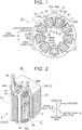
- FIG. 1 is a view of the structure of a rotary electric machine stator 10 used in a rotary electric machine mounted in a vehicle.
- FIG. 2 is a perspective view of portion A in FIG. 1 .
- the rotary electric machine stator 10 is not particularly limited, and will be referred to as the "stator 10".
- the rotary electric machine that uses the stator 10 is a three-phase synchronous rotary electric machine, and is a motor-generator that functions as a motor when the vehicle is powering, and functions as a generator when the vehicle is braking, according to control of a driving circuit.
- the rotary electric machine includes the stator 10 shown in FIG. 1 , and an annular-shaped rotor arranged spaced a predetermined distance apart from, to the inner radial side of, the stator 10. The rotor is not shown in FIG. 1 .
- FIG. 1 is a plan view from the axial direction of the stator 10.
- the stator 10 includes a stator core 12, a coil 14 that is fitted to the stator core 12 and has a winding starting end 13 and a winding terminal end 15, and an insulator 16 arranged between the stator core 12 and the coil 14.
- the stator 10 also includes first insulating resin layers 30 and 31, and second insulating resin layers 40a, 40b, 40c, and 40d, that are used for fixing the coil 14 (see FIG. 5 ).
- the first insulating resin layers 30 and 31 and the second insulating resin layers 40c and 40d are hidden and thus not shown in FIG. 1 .
- the second insulating resin layer 40d is hidden and thus not shown in FIG. 2 .
- FIGS. 1 and 2 are views both showing a circumferential direction, a radial direction, and an axial direction of the stator core 12.
- the circumferential direction is a direction that follows the circumferential direction of the stator core 12
- the radial direction is a direction that follows an inner radial side and an outer radial side of the stator core 12
- the axial direction is a direction that follows the center axis of the stator core 12.
- the side (i.e., direction) that the winding starting end 13 and the winding terminal end 15 of the coil 14 that is wound around the stator core 12 come out on is a lead side
- the opposite side i.e., direction
- FIG. 1 is a view from the lead side in the axial direction.
- the stator core 12 is an annular-shaped magnetic part, and includes an annular-shaped stator yoke 20, and a plurality of teeth 22 that protrude toward the inner peripheral side from the stator yoke 20.
- the spaces between adjacent teeth 22 are slots 24.
- the stator core 12 is formed by a predetermined number of annular-shaped magnetic thin plates 28, each of which includes the stator yoke 20 and the teeth 22 and is formed in a predetermined shape such that the slots 24 are formed, that are stacked together.
- Magnetic steel sheet may be used as the material of these magnetic thin plates 28.
- a body made of magnetic powder that has been formed in a predetermined shape may be used.
- the coil 14 is a concentrated winding coil, and is a multi-layer winding coil in which a single phase winding has been wound around a single tooth 22 a predetermined number of times by multi-layer winding. Coils 14 of different phases are arranged in one slot 24 between adjacent teeth 22.
- a multi-layer winding coil is a coil in which a conducting wire is continuously wound around a rectangular cross-section that is perpendicular to the radial direction of the tooth 22, and is arranged wound with a predetermined number of steps in the radial direction of the tooth 22, with each step being formed by a plurality of layers of coil.
- the coil 14 that is a multi-layer winding coil is a coil in which an insulation coated conducting wire is wound for a predetermined number of steps with a predetermined number of layers by multi-layer winding, to form a predetermined total number of windings.
- the coil is referred to as a two-layer winding coil
- the coil is referred to as a four-layer winding coil.
- FIGS. 1 and 2 shows the coil 14 of a two-layer winding coil having two layers, four steps, and a total of eight windings. The manner in which the conducting wire of the coil 14 that is the two-layer winding coil is wound will be described later with reference to FIGS. 3 and 4 .
- wire of the insulation coated conducting wire of the coil 14 copper wire, copper-tin alloy wire, or a silver-plated copper-tin alloy wire or the like may be used.
- wire flat wire having a generally rectangular cross-sectional shape is used.
- insulation coating an enamel coating of polyamide-imide is used. Instead of this, polyester-imide, polyimide, polyester, or formal or the like may be used.
- FIG. 1 is a view of the U1 coil in portion A of FIG. 1 extracted from FIG. 1 .
- Two coils 14 of the same phase are connected together by a connecting wire or the like, not shown.
- the coils 14 that are fitted to the teeth U1 to U3 used for the U-phase are connected together by connecting wires to form a single U-phase coil, and one end of this U-phase coil is connected to a U-terminal of a power line.
- the coils 14 fitted to the teeth V1 to V3 used for the V-phase are connected together by connecting wires to form a single V-phase coil, and one end of this V-phase coil is connected to a V-terminal of the power line, and the coils 14 fitted to the teeth W1 to W3 used for the W-phase are connected together by connecting wires to form a single W-phase coil, and one end of this W-phase coil is connected to a W-terminal of the power line.
- the other ends of the U-phase coil, the V-phase coil, and the W-phase coil are connected together to form a neutral point.
- the insulator 16 is an insulating body that has a cylindrical shape and is arranged between the lowest layer coil of the coil 14 and the stator core 12 that face each other.
- the insulator 16 is fixed to the stator core 12 by fixing means such as adhesive.
- a sheet having electrical insulating properties that has been formed in a predetermined shape may be used for the insulator 16.
- Aside from paper, a plastic film may be used as the sheet having electrical insulating properties.
- the insulator 16 may be omitted. At this time, the coil 14 is arranged directly facing the peripheral surface of the tooth 22. In the description below, the insulator 16 will be provided.
- FIGS. 3 and 4 are views illustrating the manner in which the conducting wire of the coil 14 that is the two-layer winding coil is wound.
- FIG. 3 is a sectional view taken along plane B - B in FIG. 2
- FIG. 4 is a view from direction C in FIG. 2 .
- Line B' - B' in FIG. 4 corresponds to the plane B - B.
- a flat wire having a rectangular cross-sectional shape is used for the coil 14.
- a cross-section of the tooth 22 that is perpendicular to the radial direction is rectangular, and the tooth 22 has a tapered shape in which a width dimension in the circumferential direction of the rectangle gradually becomes smaller from the base side toward the tip end side in the radial direction.
- the insulator 16 includes a cylindrical portion 16a that follows the shape of the tooth 22, and a wall surface portion 16b that has a through-hole through which the tooth 22 passes and that contacts the stator yoke 20. Stair-shaped steps are provided on the side surface in the axial direction of the cylindrical portion 16a such that the flat wire shape of the coil 14 matches the tapered shape of the tooth 22.
- an extending portion 17 that protrudes out to match the curved portion of the coil 14 is provided on both end sides of the cylindrical portion 16a in the axial direction.
- the cylindrical portion 16a, the wall surface portion 16b, and the extending portions 17, and these will simply be referred to as the "insulator 16".
- each winding of the coil 14 that has a total of eight windings is denoted by a number with an arrow.
- “1 with an arrow” indicates a first winding that starts from the winding starting end 13
- “2 with an arrow” indicates a second winding that continues on from the first winding. This continues with “3 with an arrow” and so on, up to “8 with an arrow” that indicates the eighth winding that ends at the winding terminal end 15.
- “1-arrow-2" indicates a portion where there is a transition from the first winding to the second winding.
- FIGS. 1 and 5 are also similar in this respect.
- the plurality of steps arranged wound around in the radial direction of the tooth 22 are in the order of first step, second step, third step, and fourth step from the base side on the stator yoke 20 side of the tooth 22 toward the tip end side of the tooth 22, as shown in FIG. 3 .
- the one winding coil on the tooth 22 side will be referred to as a "lower layer coil 60”
- the one winding coil to the outside of the lower layer coil 60 will be referred to as a "surface layer coil 70".
- a first winding 1 is wound as a surface layer coil 70 from the winding starting end 13, and a second winding 2 that continues on from the first winding 1 is wound as a lower layer coil 60.
- a third winding 3 that continues on from the second winding 2 from is wound as a lower layer coil 60
- a fourth winding 4 that continues on from the third winding 3 is wound as a surface layer coil 70.
- a fifth winding 5 that continues on from the fourth winding 4 is wound as a surface layer coil 70
- a sixth winding 6 that continues on from the fifth winding 5 is wound as a lower layer coil 60.
- a seventh winding 7 that continues on from the sixth winding 6 is wound as a lower layer coil 60
- an eighth winding 8 that continues on from the seventh winding 7 is wound as a surface layer coil 70 and becomes the winding terminal end 15.
- the state viewed from the tip end side of the tooth 22 is a somewhat complex winding shape that reflects the manner of winding shown in FIG. 3 .
- curved portions 50a, 50b, 50c, and 50d at the four corners of the winding of the coil 14 that is a two-layer winding coil are locations corresponding to corner portions 52a, 52b, 52c, and 52d of the four corners of the rectangular cross-section of the tooth 22.
- the height position in the axial direction of all of the windings is the same.
- the height in the axial direction of the curved portion at the transition from the third winding 3 to the fourth winding 4 and the curved portion at the transition from the seventh winding 7 to the eighth winding 8 is different from the height in the axial direction of the curved portion at the transition from the fourth winding 4 to the fifth winding 5.
- the portion at the transition from the third winding 3 to the fourth winding 4 and the portion at the transition from the seventh winding 7 to the eighth winding 8 remain at the height of the lower layer coil 60 in the axial direction, the portion at the transition from the fourth winding 4 to the fifth winding 5 is at the height of the surface layer coil 70, as shown in FIG. 3 .
- FIG. 5 is a view of the winding portion at the second step taken from FIG. 3 , which shows the positional relationship of the first insulating resin layers 30 and 31 and the second insulating resin layers 40a, 40b, 40c, and 40d.
- the gap between the insulator 16 and the lower layer coil 60, and the gap between the lower layer coil 60 and the surface layer coil 70 are shown overly wide.
- the lower layer coil 60 is the coil denoted by "3 with an arrow”
- the surface layer coil 70 is the coil denoted by "4 with an arrow”.
- the first insulating resin layers 30 and 31 and the second insulating resin layers 40a, 40b, 40c, and 40d are both provided to prevent the coil 14 from moving.
- the first insulating resin layers 30 and 31 fix the coil 14 to the insulator 16, while the second insulating resin layers 40a, 40b, 40c, and 40d locally fix the surface layer coils 70 of the steps of the coil 14 to each other.
- the reason that the second insulating resin layers 40a, 40b, 40c, and 40d do not completely cover the surface layer coils 70 is to expose the coil 14 and improve heat dissipation with coolant or the like.
- the first insulating resin layers 30 and 31 are formed between the coil denoted by "3 with an arrow" that is the lower layer coil 60, and the insulator 16.
- the first insulating resin layer 30 is formed by pouring a predetermined liquid resin into the gap between the lower layer coil 60 and the surface layer coil 70 from the tip end side of the tooth 22 by means such as injecting or dripping, after fitting the coil 14 onto the insulator 16.
- insulating resin with a relatively low viscosity is preferably used so that it will spread out and seep into the gap between all of the lower layer coils 60 from the fourth step to the first step, and the insulator 16.
- a varnish with a relatively low viscosity may be used.
- Insulating resin is resin that has electrical insulating properties.
- the first insulating resin layer 30 is formed between a side surface in the axial direction of the insulator 16, and the lower layer coil 60 of each step, and the first insulating resin layer 31 is formed between the extending portions 17 of the insulator 16 and the lower layer coil 60 of each step.
- the first insulating resin layer 30 and the first insulating resin layer 31 are formed separated from each other, but they may also be formed connected together.
- the second insulating resin layers 40a, 40b, 40c, and 40d are formed locally in locations corresponding to the curved portions 50a, 50b, 50c, and 50d, respectively, of the four corners of the coil denoted by "4 with an arrow" that is the surface layer coil 70.
- An insulating resin layer is not formed between the curved portion 50a and the curved portion 50b, between the curved portion 50b and the curved portion 50c, between the curved portion 50c and the curved portion 50d, and between the curved portion 50d and the curved portion 50a.
- the second insulating resin layers 40a, 40b, 40c, and 40d are formed extending across the surface layer coils 70 of the steps.
- the surface layer coils 70 of the steps are connected together by insulating resin.
- the curved portions 50a to 50d are locations that extend across the axial direction, the radial direction, and the circumferential direction of the coil 14. Therefore, providing the second insulating resin layers 40a, 40b, 40c, and 40d at the curved portions 50a to 50d of the four corners makes it possible to even more effectively inhibit movement of the coil 14 compared to when they are provided at four locations of linear portions of the coil 14, for example.
- the second insulating resin layers 40a, 40b, 40c, and 40d are arranged by means such as applying a predetermined resin from the outside of the surface layer coil 70 of the coil 14.
- a predetermined resin a liquid insulating resin with a relatively high viscosity, a semi-solidified insulating resin, a foam insulating resin that foams (i.e., expands) when heated, or a powdery insulating resin that flows and hardens when heated, or the like may be used.
- This heating hardens both the first insulating resin layers 30 and 31 and the second insulating resin layers 40a, 40b, 40c, and 40d, such that the lower layer coils 60 on the steps of the coil 14 are fixed to the insulator 16, and the surface layer coils 70 on the steps of the coil 14 are connected together in a fixed state.
- the lower layer coil 60 is first wound around the tooth 22, and then the surface layer coil 70 is wound on top of the lower layer coil 60. Then from the surface layer coil 70 on the first step 1, the coil moves to the second step 2, where the lower layer coil 60 is first wound on the second step 2, and then the surface layer coil 70 of the second step 2 is wound on top of this lower layer coil 60, and so on and so forth.
- the overall length of the conducting wire is fairly long, but the coil 14 is able to be wound by a direct winding method on the tooth 22 side without forming a cassette coil.
- a two-layer winding coil of the lower layer coil 60 and the surface layer coil 70 is also able to be formed using a method in which two conducting wires are overlapped and wrapped once around, just as in a conducting wire assembly.
- the winding starting end and the winding terminal end are each two conducting wires, so a process to make a series connection or a parallel connection at the coil ends and the like is necessary, but winding can be performed by a direct winding method on the tooth 22 side.
- the lower layer coil 60 is wound with a predetermined number of steps from the base side toward the tip end side of the tooth 22, and then the surface layer coil 70 is wound with a predetermined number of steps from the tip end side toward the base side of the tooth 22.
- the winding starting end and the winding terminal end are both on the base side of the tooth 22, but winding is able to be performed by a direct winding method on the tooth 22 side.
- neither the first insulating resin layers 30 and 31 nor the second insulating resin layers 40a, 40b, 40c, and 40d are formed in the gap between the lower layer coil 60 and the surface layer coil 70.
- the length of a connecting portion 54 of the lower layer coil 60 and the surface layer coil 70 is short, but the rigidity of the connecting portion 54 is quite height, so the coil 14 is able to be prevented from moving even if the space between the lower layer coil 60 and the surface layer coil 70 is left a gap.
- FIG. 6 is a view showing a frame format of the coil 14 of the two-layer winding.
- the lower layer coil 60 is fixed to the insulator 16 by the first insulating resin layers 30 and 31, and the surface layer coils 70 are fixed and integrated together across the plurality of steps by the second insulating resin layers 40a, 40b, 40c, and 40d.
- the surface layer coil 70 and the lower layer coil 60 are connected by the connecting portion 54, so the connecting portion 54 acts as resistance to movement of the surface layer coil 70 with respect to the lower layer coil 60. If the rigidity as resistance is sufficiently high due to the length of the connecting portion 54 being short or the like, the surface layer coil 70 is able to be prevented from moving with respect to the lower layer coil 60.
- the rigidity of the connecting portion 54 becomes relatively low with respect to external force such as vibration due to, for example, the total number of windings of the coil 14 increasing or the number of steps increasing, or the number of connecting portions 54 increasing or the length thereof increasing, movement of the surface layer coil 70 with respect to the lower layer coil 60 may not be able to be sufficiently prevented.
- An example of this is illustrated with a coil 80 of a four-layer winding in a frame format in FIG. 7 .
- the coil 80 in FIG. 7 is a four-layer winding, so the one winding coil that is arranged closest to the tooth 22 side and fixed by the first insulating resin layers 30 and 31 will be referred to as a lowest layer coil 60. Also, the one winding coil that is arranged farthest on the surface side and in which the windings on the steps are fixed together by the second insulating resin layers 40a, 40b, 40c, and 40d will be the surface layer coil 70.
- the two winding coils that are arranged between the lowest layer coil 60 and the surface layer coil 70 will be referred to as intermediate layer coils 61 and 62.
- FIG. 8 is a view of an example of a structure of a coil 82 that is a four-layer winding coil, in which movement of the surface layer coil 70 with respect to the lowest layer coil 60 is able to be effectively prevented.
- second insulating resin layers 42a, 42b, 42c, and 42d are formed not only at the curved portions 50a, 50b, 50c, and 50d of the surface layer coil 70, but also between the intermediate layer coils 62 and 61 and the lowest layer coil 60 on the lower layer side thereof.
- the second insulating resin layers 42a, 42b, 42c, and 42d are all formed between the surface layer coil 70 and the intermediate layer coil 62, between the intermediate layer coil 62 and the intermediate layer coil 61, and between the intermediate layer coil 61 and the lowest layer coil 60.
- the surface layer coil 70 is fixed to the lowest layer coil 60 by the second insulating resin layers 42a, 42b, 42c, and 42d via the intermediate layer coils 62 and 61, so movement of the surface layer coil 70 with respect to the lowest layer coil 60 is able to be effectively inhibited.
- the second insulating resin layers 42a, 42b, 42c, and 42d are arranged by means such as applying a predetermined resin from the outside of the surface layer coil 70 of the coil 82.
- a predetermined resin a liquid insulating resin having a viscosity that is suitably lower than that of the second insulating resin layers 40a, 40b, 40c, and 40d described with reference to FIGS. 5 and 6 may be used.
- the second insulating resin layers 42a, 42b, 42c, and 42d are arranged separated from each other, and at these separation regions, the surfaces on the surface layer side of the surface layer coil 70, the intermediate layer coils 62 and 61, and the lowest layer coil 60 are exposed in the insulation coated conducting wire state. As a result, the cooling performance by coolant or the like is able to be ensured.
- FIG. 9 is a view of an example of another structure of a coil 84 that is a four-layer winding coil, in which movement of the surface layer coil 70 with respect to the lowest layer coil 60 is able to be effectively prevented.
- FIG. 9 is a sectional view that corresponds to a sectional view taken along line D - D in FIG. 7 .
- the second insulating resin layers 40a, 40b, 40c, and 40d in FIG. 8 do not appear in the sectional view taken along line D - D, and are thus indicated by the alternate long and two short dashes line.
- a second insulating resin layer 44 includes, in addition to the portions of the second insulating resin layers 40a, 40b, 40c, and 40d described with reference to FIG. 8 , an additional insulating resin layer 46 that is formed between a wall surface on the stator yoke 20 side of the coil 84 and a wall surface portion 16b of the insulator 16.
- the additional insulating resin layer 46 is formed integrally connected to each of the second insulating resin layers 40a, 40b, 40c, and 40d and the first insulating resin layers 30 and 31.
- the methods described with reference to FIGS. 8 and 9 are applied to four-layer winding coils, but they are not limited to this. That is, these methods may be applied when the rigidity of the connecting portion 54 with respect to an external force such as vibration is relatively low due to, for example, the total number of windings of the coil 14 increasing or the number of steps increasing, or the number of connecting portions 54 increasing or the length thereof increasing.
- the methods described with reference to FIGS. 8 and 9 may also be suitably applied to a two-layer winding as well when it is necessary to increase the rigidity of the connecting portion 54 due to the winding method or some other reason.
- a stator 11 shown in FIG. 10 is a modified example of the structure shown in FIG. 1 .
- a second insulating resin layer 48 is formed extending across curved portions that face each other, of two coils 14 arranged in the same slot 24.
- FIG. 10 Although not shown in FIG.
- a second insulating resin layer formed extending across two curved portions 50c and 50d that face each other, of the two coils 14 in the same slot 24, are on the non-lead side.
- stator used in a rotary electric machine mounted in a vehicle is described, but this is merely an example for the description.
- the rotary electric machine stator uses a concentrated winding coil
- the stator may be used for another purpose.
- concentrated winding coil a multi-layer winding coil that uses a flat wire is described, but this is merely an example for the description.
- Another type of wire other than a flat wire such as a round wire having a circular cross-section or a conducting wire having an elliptical cross-section, may also be used.
- the shape, number of teeth, number of windings, and material and the like described above are merely examples for the description, and may be suitably modified to match the specifications of the rotary electric machine stator.
- a multi-layer winding a two-layer winding and a four-layer winding are described, but these are merely examples for the description.
- the multi-layer winding may also have a number of layers other than two or four. With the example of the two-layer winding, the total number of windings of the multi-layer winding is eight, but this is also only an example. The total number of windings may also be a number other than this.
Landscapes
- Engineering & Computer Science (AREA)
- Power Engineering (AREA)
- Manufacturing & Machinery (AREA)
- Insulation, Fastening Of Motor, Generator Windings (AREA)
- Windings For Motors And Generators (AREA)
Claims (4)
- Stator (10; 11) einer rotierenden elektrischen Maschine mit:einem Statorkern (12), der ein ringförmiges Statorjoch (20) und eine Vielzahl von Zähnen (22), die in Richtung einer Innenumfangsseite von dem ringförmigen Statorjoch (20) vorstehen, aufweist;einer mehrschichtig gewickelten Spule (14; 80; 82; 84), die um einen rechteckigen Querschnitt gewickelt ist, der senkrecht zu einer radialen Richtung jedes Zahnes (22) ist, wobei die mehrschichtig gewickelte Spule (14; 80; 82; 84) mit einer vorbestimmten Anzahl von Stufen in der radialen Richtung jedes Zahnes angeordnet ist und wobei jede Stufe der mehrschichtig gewickelten Spule (14; 80; 82; 84) eine unterste Spulenschicht (60) einer Wicklung und eine oberste Spulenschicht (70) einer anderen Wicklung aufweist; undeiner ersten isolierenden Harzschicht (30, 31), die zwischen jedem Zahn und der untersten Spulenschicht (60) oder zwischen einem Isolator (16), der an jedem Zahn (22) befestigt ist, und der untersten Spulenschicht (60) angeordnet ist;gekennzeichnet durcheine zweite isolierende Harzschicht (40a, 40b, 40c, 40d; 42a, 42b, 42c, 42d; 44; 48), die lokal an gebogenen Abschnitten (50a, 50b, 50c, 50d) der obersten Spulenschicht (70) angeordnet ist, die den Eckabschnitten (52a, 52b, 52c, 52d) der vier Ecken des rechteckigen Querschnitts jedes Zahnes (22) entsprechen, wobei die zweite isolierende Harzschicht (40a, 40b, 40c, 40d; 42a, 42b, 42c, 42d; 44; 48) angeordnet ist, um sich über die vorbestimmte Anzahl von Stufen der obersten Spulenschicht (70) zu erstrecken.
- Stator (11) der rotierenden elektrischen Maschine gemäß Anspruch 1, wobei die zweite isolierende Harzschicht (48) angeordnet ist, um sich über die einander zugewandten gebogenen Abschnitte (50a, 50b, 50c, 50d) von zwei der mehrschichtig gewickelten Spulen (14) zu erstrecken, die in einem Schlitz (24) zwischen den benachbarten Zähnen (22) angeordnet sind.
- Stator (10) der rotierenden elektrischen Maschine gemäß Anspruch 1 oder 2, wobei die zweite isolierende Harzschicht (42a, 42b, 42c, 42d) auch zwischen der obersten Spulenschicht (70) und einer oder mehreren Spulen (60, 61, 62) auf einer unteren Schichtseite der obersten Spulenschicht (70) an den gebogenen Abschnitten (50a, 50b, 50c, 50d) angeordnet ist.
- Stator (10) der rotierenden elektrischen Maschine gemäß einem der Ansprüche 1 bis 3, wobei
die zweite isolierende Harzschicht (44) angeordnet ist, um sich über jede der Stufen der mehrschichtig gewickelten Spule (84) an den gebogenen Abschnitten (50a, 50b, 50c, 50d) zu erstrecken; und
die zweite isolierende Harzschicht (44) zwischen einer Wandfläche auf der ringförmigen Statorjochseite eines Schlitzes (24) zwischen den benachbarten Zähnen (22) und der obersten Spulenschicht (70) angeordnet ist.
Applications Claiming Priority (1)
| Application Number | Priority Date | Filing Date | Title |
|---|---|---|---|
| JP2015216871A JP6299729B2 (ja) | 2015-11-04 | 2015-11-04 | 回転電機ステータ |
Publications (2)
| Publication Number | Publication Date |
|---|---|
| EP3166209A1 EP3166209A1 (de) | 2017-05-10 |
| EP3166209B1 true EP3166209B1 (de) | 2018-10-17 |
Family
ID=57211435
Family Applications (1)
| Application Number | Title | Priority Date | Filing Date |
|---|---|---|---|
| EP16196598.3A Not-in-force EP3166209B1 (de) | 2015-11-04 | 2016-10-31 | Stator für elektrische rotationsmaschine |
Country Status (8)
| Country | Link |
|---|---|
| US (1) | US10116180B2 (de) |
| EP (1) | EP3166209B1 (de) |
| JP (1) | JP6299729B2 (de) |
| KR (1) | KR101883857B1 (de) |
| CN (1) | CN106655577B (de) |
| BR (1) | BR102016025420B1 (de) |
| MY (1) | MY179363A (de) |
| RU (1) | RU2638165C1 (de) |
Families Citing this family (17)
| Publication number | Priority date | Publication date | Assignee | Title |
|---|---|---|---|---|
| JPWO2019003674A1 (ja) * | 2017-06-26 | 2020-03-19 | 日立オートモティブシステムズ株式会社 | 回転電機 |
| WO2020044428A1 (ja) * | 2018-08-28 | 2020-03-05 | 三菱電機株式会社 | 固定子 |
| CN109327096B (zh) * | 2018-08-31 | 2020-05-12 | 惠州富盛绝缘材料有限公司 | 扁线电机定子的槽绝缘方法 |
| WO2020080479A1 (ja) * | 2018-10-18 | 2020-04-23 | パナソニックIpマネジメント株式会社 | コイル装置 |
| EP3706290A1 (de) * | 2019-03-05 | 2020-09-09 | Kongsberg Maritime CM AS | Verfahren zum aufwickeln einer konzentrierten spule für eine elektrische maschine |
| JP6912508B2 (ja) * | 2019-03-19 | 2021-08-04 | ファナック株式会社 | 固定子および電動機 |
| JP7347105B2 (ja) * | 2019-10-16 | 2023-09-20 | 株式会社デンソー | ステータの製造装置、および、ステータの製造方法 |
| KR102696292B1 (ko) * | 2020-01-08 | 2024-08-20 | 엘지마그나 이파워트레인 주식회사 | 회전 전기 기기의 스테이터 |
| CN219875249U (zh) | 2020-09-28 | 2023-10-20 | 米沃奇电动工具公司 | 电机绝缘体 |
| CN112510943A (zh) * | 2020-11-27 | 2021-03-16 | 上海电气电站设备有限公司 | 一种转子匝间绝缘的预上胶垫条及其粘接方法 |
| CN113675965B (zh) * | 2020-12-07 | 2023-04-18 | 博格华纳动力驱动系统(天津)有限公司 | 一种电机定子及电机 |
| CN114679087B (zh) * | 2020-12-24 | 2026-02-17 | 丰田自动车株式会社 | 马达控制装置 |
| JP2022106469A (ja) * | 2021-01-07 | 2022-07-20 | トヨタ自動車株式会社 | モータ制御装置 |
| JP2023011308A (ja) * | 2021-07-12 | 2023-01-24 | 日立Astemo株式会社 | 回転電機および回転電機の固定子 |
| WO2023145746A1 (ja) * | 2022-01-28 | 2023-08-03 | パナソニックIpマネジメント株式会社 | ステータ及びモータ |
| CN116317227A (zh) * | 2023-03-10 | 2023-06-23 | 上海易唯科电机技术有限公司 | 一种定子组件及扁线电机 |
| CA3226348A1 (en) * | 2024-01-17 | 2025-10-31 | Steeven Gagnon | Three-phase electrical generator |
Family Cites Families (11)
| Publication number | Priority date | Publication date | Assignee | Title |
|---|---|---|---|---|
| US3182383A (en) * | 1960-09-13 | 1965-05-11 | Gen Electric | Electromagnetic construction |
| JPS51124401U (de) * | 1975-04-03 | 1976-10-08 | ||
| EP0910885A1 (de) * | 1996-05-29 | 1999-04-28 | Asea Brown Boveri Ab | Elektrische drehmaschine mit axialkühlung |
| JP3508687B2 (ja) | 1999-07-12 | 2004-03-22 | 株式会社デンソー | 回転電機 |
| JP2007135360A (ja) * | 2005-11-11 | 2007-05-31 | Sumitomo Electric Ind Ltd | モータコア部品及びモータ部品 |
| JP2010051087A (ja) * | 2008-08-21 | 2010-03-04 | Toyota Motor Corp | 固定子構造 |
| JP5267091B2 (ja) * | 2008-12-08 | 2013-08-21 | トヨタ自動車株式会社 | 回転電機用ステータ |
| US8643243B2 (en) * | 2009-12-23 | 2014-02-04 | Kohler Co. | Apparatus and method for electrically insulating end turns of a stator assembly |
| JP5904827B2 (ja) * | 2012-03-09 | 2016-04-20 | 日立オートモティブシステムズ株式会社 | 回転電機 |
| US9893594B2 (en) * | 2012-09-12 | 2018-02-13 | Mitsubishi Electric Corporation | Armature of rotating electrical machine and method for manufacturing same |
| JP5542894B2 (ja) * | 2012-10-26 | 2014-07-09 | 三菱電機株式会社 | 回転電機の固定子製造方法 |
-
2015
- 2015-11-04 JP JP2015216871A patent/JP6299729B2/ja active Active
-
2016
- 2016-10-31 MY MYPI2016703983A patent/MY179363A/en unknown
- 2016-10-31 BR BR102016025420-5A patent/BR102016025420B1/pt active IP Right Grant
- 2016-10-31 EP EP16196598.3A patent/EP3166209B1/de not_active Not-in-force
- 2016-11-01 US US15/340,542 patent/US10116180B2/en active Active
- 2016-11-01 RU RU2016142930A patent/RU2638165C1/ru active
- 2016-11-02 CN CN201610944351.7A patent/CN106655577B/zh not_active Expired - Fee Related
- 2016-11-02 KR KR1020160144870A patent/KR101883857B1/ko not_active Expired - Fee Related
Non-Patent Citations (1)
| Title |
|---|
| None * |
Also Published As
| Publication number | Publication date |
|---|---|
| KR20170052497A (ko) | 2017-05-12 |
| KR101883857B1 (ko) | 2018-08-01 |
| BR102016025420A2 (pt) | 2017-05-09 |
| CN106655577B (zh) | 2019-01-22 |
| RU2638165C1 (ru) | 2017-12-12 |
| JP2017093049A (ja) | 2017-05-25 |
| MY179363A (en) | 2020-11-05 |
| EP3166209A1 (de) | 2017-05-10 |
| CN106655577A (zh) | 2017-05-10 |
| JP6299729B2 (ja) | 2018-03-28 |
| US20170126086A1 (en) | 2017-05-04 |
| BR102016025420B1 (pt) | 2022-08-23 |
| US10116180B2 (en) | 2018-10-30 |
Similar Documents
| Publication | Publication Date | Title |
|---|---|---|
| US10116180B2 (en) | Rotary electric machine stator | |
| CN107959363B (zh) | 旋转电机的定子以及旋转电机的定子的制造方法 | |
| CN105210267B (zh) | 旋转电机及其制造方法 | |
| EP2596567B1 (de) | Vorrichtung zur motorleistungsverteilung | |
| EP2182614B1 (de) | Verdrahtungskomponente für Motorspule | |
| EP3095176B1 (de) | Stator für elektrisches rotationsmaschine | |
| EP2827476B1 (de) | Stator und verfahren zur herstellung des stators | |
| US20100244617A1 (en) | Stator having improved structure for restricting relative displacement between stator core and stator coil | |
| CN113615047B (zh) | 定子及电动机 | |
| EP2182615B1 (de) | Verdrahtungskomponente für Motorspule | |
| JP4623129B2 (ja) | 回転電機の固定子及び回転電機 | |
| JP2009131092A (ja) | 回転電機の固定子および回転電機 | |
| US20090212654A1 (en) | Coil fixing member and rotary electric machine | |
| JP7394216B2 (ja) | 回転電機の固定子及びその組立て方法 | |
| WO2013154054A1 (ja) | ブラシレスモータ | |
| JP5233630B2 (ja) | ステータ、回転電機、ステータの製造方法および回転電機の製造方法 | |
| JP2014093893A (ja) | 回転電機のステータ | |
| JP7208057B2 (ja) | 回転電機および車両 | |
| US20240204602A1 (en) | Rotary electric machine | |
| JP2018126029A (ja) | 回転電機のステータ | |
| JP6709870B2 (ja) | 電動機用ステータの製造方法および電動機用ステータ | |
| JP7025224B2 (ja) | 回転電機のステータ | |
| JP2023085032A (ja) | モータ | |
| JP7671941B2 (ja) | コイル及びそれを備えたステータ、モータ | |
| CN115603479A (zh) | 旋转电机及旋转电机的定子 |
Legal Events
| Date | Code | Title | Description |
|---|---|---|---|
| PUAI | Public reference made under article 153(3) epc to a published international application that has entered the european phase |
Free format text: ORIGINAL CODE: 0009012 |
|
| 17P | Request for examination filed |
Effective date: 20161031 |
|
| AK | Designated contracting states |
Kind code of ref document: A1 Designated state(s): AL AT BE BG CH CY CZ DE DK EE ES FI FR GB GR HR HU IE IS IT LI LT LU LV MC MK MT NL NO PL PT RO RS SE SI SK SM TR |
|
| AX | Request for extension of the european patent |
Extension state: BA ME |
|
| GRAP | Despatch of communication of intention to grant a patent |
Free format text: ORIGINAL CODE: EPIDOSNIGR1 |
|
| RIC1 | Information provided on ipc code assigned before grant |
Ipc: H02K 3/34 20060101ALI20180226BHEP Ipc: H02K 1/14 20060101ALI20180226BHEP Ipc: H02K 3/24 20060101ALN20180226BHEP Ipc: H02K 3/32 20060101AFI20180226BHEP Ipc: H02K 15/12 20060101ALN20180226BHEP Ipc: H02K 3/18 20060101ALN20180226BHEP |
|
| INTG | Intention to grant announced |
Effective date: 20180404 |
|
| GRAS | Grant fee paid |
Free format text: ORIGINAL CODE: EPIDOSNIGR3 |
|
| GRAJ | Information related to disapproval of communication of intention to grant by the applicant or resumption of examination proceedings by the epo deleted |
Free format text: ORIGINAL CODE: EPIDOSDIGR1 |
|
| GRAS | Grant fee paid |
Free format text: ORIGINAL CODE: EPIDOSNIGR3 |
|
| GRAP | Despatch of communication of intention to grant a patent |
Free format text: ORIGINAL CODE: EPIDOSNIGR1 |
|
| RAP1 | Party data changed (applicant data changed or rights of an application transferred) |
Owner name: TOYOTA JIDOSHA KABUSHIKI KAISHA |
|
| RIC1 | Information provided on ipc code assigned before grant |
Ipc: H02K 3/24 20060101ALN20180730BHEP Ipc: H02K 3/18 20060101ALN20180730BHEP Ipc: H02K 15/12 20060101ALN20180730BHEP Ipc: H02K 3/34 20060101ALI20180730BHEP Ipc: H02K 3/32 20060101AFI20180730BHEP Ipc: H02K 1/14 20060101ALI20180730BHEP |
|
| RIN1 | Information on inventor provided before grant (corrected) |
Inventor name: HATTORI, HIROYUKI Inventor name: NAGAI, SHINGO |
|
| INTG | Intention to grant announced |
Effective date: 20180813 |
|
| GRAA | (expected) grant |
Free format text: ORIGINAL CODE: 0009210 |
|
| AK | Designated contracting states |
Kind code of ref document: B1 Designated state(s): AL AT BE BG CH CY CZ DE DK EE ES FI FR GB GR HR HU IE IS IT LI LT LU LV MC MK MT NL NO PL PT RO RS SE SI SK SM TR |
|
| REG | Reference to a national code |
Ref country code: GB Ref legal event code: FG4D |
|
| REG | Reference to a national code |
Ref country code: CH Ref legal event code: EP |
|
| REG | Reference to a national code |
Ref country code: IE Ref legal event code: FG4D |
|
| REG | Reference to a national code |
Ref country code: DE Ref legal event code: R096 Ref document number: 602016006504 Country of ref document: DE Ref country code: AT Ref legal event code: REF Ref document number: 1055132 Country of ref document: AT Kind code of ref document: T Effective date: 20181115 |
|
| REG | Reference to a national code |
Ref country code: DE Ref legal event code: R084 Ref document number: 602016006504 Country of ref document: DE |
|
| REG | Reference to a national code |
Ref country code: GB Ref legal event code: 746 Effective date: 20181126 |
|
| REG | Reference to a national code |
Ref country code: NL Ref legal event code: MP Effective date: 20181017 |
|
| REG | Reference to a national code |
Ref country code: LT Ref legal event code: MG4D |
|
| REG | Reference to a national code |
Ref country code: AT Ref legal event code: MK05 Ref document number: 1055132 Country of ref document: AT Kind code of ref document: T Effective date: 20181017 |
|
| PG25 | Lapsed in a contracting state [announced via postgrant information from national office to epo] |
Ref country code: NL Free format text: LAPSE BECAUSE OF FAILURE TO SUBMIT A TRANSLATION OF THE DESCRIPTION OR TO PAY THE FEE WITHIN THE PRESCRIBED TIME-LIMIT Effective date: 20181017 |
|
| PG25 | Lapsed in a contracting state [announced via postgrant information from national office to epo] |
Ref country code: FI Free format text: LAPSE BECAUSE OF FAILURE TO SUBMIT A TRANSLATION OF THE DESCRIPTION OR TO PAY THE FEE WITHIN THE PRESCRIBED TIME-LIMIT Effective date: 20181017 Ref country code: NO Free format text: LAPSE BECAUSE OF FAILURE TO SUBMIT A TRANSLATION OF THE DESCRIPTION OR TO PAY THE FEE WITHIN THE PRESCRIBED TIME-LIMIT Effective date: 20190117 Ref country code: IS Free format text: LAPSE BECAUSE OF FAILURE TO SUBMIT A TRANSLATION OF THE DESCRIPTION OR TO PAY THE FEE WITHIN THE PRESCRIBED TIME-LIMIT Effective date: 20190217 Ref country code: HR Free format text: LAPSE BECAUSE OF FAILURE TO SUBMIT A TRANSLATION OF THE DESCRIPTION OR TO PAY THE FEE WITHIN THE PRESCRIBED TIME-LIMIT Effective date: 20181017 Ref country code: LT Free format text: LAPSE BECAUSE OF FAILURE TO SUBMIT A TRANSLATION OF THE DESCRIPTION OR TO PAY THE FEE WITHIN THE PRESCRIBED TIME-LIMIT Effective date: 20181017 Ref country code: BG Free format text: LAPSE BECAUSE OF FAILURE TO SUBMIT A TRANSLATION OF THE DESCRIPTION OR TO PAY THE FEE WITHIN THE PRESCRIBED TIME-LIMIT Effective date: 20190117 Ref country code: PL Free format text: LAPSE BECAUSE OF FAILURE TO SUBMIT A TRANSLATION OF THE DESCRIPTION OR TO PAY THE FEE WITHIN THE PRESCRIBED TIME-LIMIT Effective date: 20181017 Ref country code: ES Free format text: LAPSE BECAUSE OF FAILURE TO SUBMIT A TRANSLATION OF THE DESCRIPTION OR TO PAY THE FEE WITHIN THE PRESCRIBED TIME-LIMIT Effective date: 20181017 Ref country code: LV Free format text: LAPSE BECAUSE OF FAILURE TO SUBMIT A TRANSLATION OF THE DESCRIPTION OR TO PAY THE FEE WITHIN THE PRESCRIBED TIME-LIMIT Effective date: 20181017 Ref country code: AT Free format text: LAPSE BECAUSE OF FAILURE TO SUBMIT A TRANSLATION OF THE DESCRIPTION OR TO PAY THE FEE WITHIN THE PRESCRIBED TIME-LIMIT Effective date: 20181017 |
|
| PG25 | Lapsed in a contracting state [announced via postgrant information from national office to epo] |
Ref country code: AL Free format text: LAPSE BECAUSE OF FAILURE TO SUBMIT A TRANSLATION OF THE DESCRIPTION OR TO PAY THE FEE WITHIN THE PRESCRIBED TIME-LIMIT Effective date: 20181017 Ref country code: PT Free format text: LAPSE BECAUSE OF FAILURE TO SUBMIT A TRANSLATION OF THE DESCRIPTION OR TO PAY THE FEE WITHIN THE PRESCRIBED TIME-LIMIT Effective date: 20190217 Ref country code: RS Free format text: LAPSE BECAUSE OF FAILURE TO SUBMIT A TRANSLATION OF THE DESCRIPTION OR TO PAY THE FEE WITHIN THE PRESCRIBED TIME-LIMIT Effective date: 20181017 Ref country code: GR Free format text: LAPSE BECAUSE OF FAILURE TO SUBMIT A TRANSLATION OF THE DESCRIPTION OR TO PAY THE FEE WITHIN THE PRESCRIBED TIME-LIMIT Effective date: 20190118 Ref country code: SE Free format text: LAPSE BECAUSE OF FAILURE TO SUBMIT A TRANSLATION OF THE DESCRIPTION OR TO PAY THE FEE WITHIN THE PRESCRIBED TIME-LIMIT Effective date: 20181017 |
|
| REG | Reference to a national code |
Ref country code: BE Ref legal event code: MM Effective date: 20181031 |
|
| PG25 | Lapsed in a contracting state [announced via postgrant information from national office to epo] |
Ref country code: LU Free format text: LAPSE BECAUSE OF NON-PAYMENT OF DUE FEES Effective date: 20181031 |
|
| REG | Reference to a national code |
Ref country code: DE Ref legal event code: R097 Ref document number: 602016006504 Country of ref document: DE |
|
| REG | Reference to a national code |
Ref country code: IE Ref legal event code: MM4A |
|
| PG25 | Lapsed in a contracting state [announced via postgrant information from national office to epo] |
Ref country code: CZ Free format text: LAPSE BECAUSE OF FAILURE TO SUBMIT A TRANSLATION OF THE DESCRIPTION OR TO PAY THE FEE WITHIN THE PRESCRIBED TIME-LIMIT Effective date: 20181017 Ref country code: DK Free format text: LAPSE BECAUSE OF FAILURE TO SUBMIT A TRANSLATION OF THE DESCRIPTION OR TO PAY THE FEE WITHIN THE PRESCRIBED TIME-LIMIT Effective date: 20181017 Ref country code: IT Free format text: LAPSE BECAUSE OF FAILURE TO SUBMIT A TRANSLATION OF THE DESCRIPTION OR TO PAY THE FEE WITHIN THE PRESCRIBED TIME-LIMIT Effective date: 20181017 |
|
| PLBE | No opposition filed within time limit |
Free format text: ORIGINAL CODE: 0009261 |
|
| STAA | Information on the status of an ep patent application or granted ep patent |
Free format text: STATUS: NO OPPOSITION FILED WITHIN TIME LIMIT |
|
| PG25 | Lapsed in a contracting state [announced via postgrant information from national office to epo] |
Ref country code: MC Free format text: LAPSE BECAUSE OF FAILURE TO SUBMIT A TRANSLATION OF THE DESCRIPTION OR TO PAY THE FEE WITHIN THE PRESCRIBED TIME-LIMIT Effective date: 20181017 Ref country code: RO Free format text: LAPSE BECAUSE OF FAILURE TO SUBMIT A TRANSLATION OF THE DESCRIPTION OR TO PAY THE FEE WITHIN THE PRESCRIBED TIME-LIMIT Effective date: 20181017 Ref country code: BE Free format text: LAPSE BECAUSE OF NON-PAYMENT OF DUE FEES Effective date: 20181031 Ref country code: SK Free format text: LAPSE BECAUSE OF FAILURE TO SUBMIT A TRANSLATION OF THE DESCRIPTION OR TO PAY THE FEE WITHIN THE PRESCRIBED TIME-LIMIT Effective date: 20181017 Ref country code: SM Free format text: LAPSE BECAUSE OF FAILURE TO SUBMIT A TRANSLATION OF THE DESCRIPTION OR TO PAY THE FEE WITHIN THE PRESCRIBED TIME-LIMIT Effective date: 20181017 Ref country code: EE Free format text: LAPSE BECAUSE OF FAILURE TO SUBMIT A TRANSLATION OF THE DESCRIPTION OR TO PAY THE FEE WITHIN THE PRESCRIBED TIME-LIMIT Effective date: 20181017 |
|
| 26N | No opposition filed |
Effective date: 20190718 |
|
| PG25 | Lapsed in a contracting state [announced via postgrant information from national office to epo] |
Ref country code: SI Free format text: LAPSE BECAUSE OF FAILURE TO SUBMIT A TRANSLATION OF THE DESCRIPTION OR TO PAY THE FEE WITHIN THE PRESCRIBED TIME-LIMIT Effective date: 20181017 Ref country code: IE Free format text: LAPSE BECAUSE OF NON-PAYMENT OF DUE FEES Effective date: 20181031 |
|
| PG25 | Lapsed in a contracting state [announced via postgrant information from national office to epo] |
Ref country code: MT Free format text: LAPSE BECAUSE OF NON-PAYMENT OF DUE FEES Effective date: 20181031 |
|
| PG25 | Lapsed in a contracting state [announced via postgrant information from national office to epo] |
Ref country code: TR Free format text: LAPSE BECAUSE OF FAILURE TO SUBMIT A TRANSLATION OF THE DESCRIPTION OR TO PAY THE FEE WITHIN THE PRESCRIBED TIME-LIMIT Effective date: 20181017 |
|
| REG | Reference to a national code |
Ref country code: CH Ref legal event code: PL |
|
| PG25 | Lapsed in a contracting state [announced via postgrant information from national office to epo] |
Ref country code: CY Free format text: LAPSE BECAUSE OF FAILURE TO SUBMIT A TRANSLATION OF THE DESCRIPTION OR TO PAY THE FEE WITHIN THE PRESCRIBED TIME-LIMIT Effective date: 20181017 Ref country code: MK Free format text: LAPSE BECAUSE OF NON-PAYMENT OF DUE FEES Effective date: 20181017 Ref country code: HU Free format text: LAPSE BECAUSE OF FAILURE TO SUBMIT A TRANSLATION OF THE DESCRIPTION OR TO PAY THE FEE WITHIN THE PRESCRIBED TIME-LIMIT; INVALID AB INITIO Effective date: 20161031 |
|
| PG25 | Lapsed in a contracting state [announced via postgrant information from national office to epo] |
Ref country code: CH Free format text: LAPSE BECAUSE OF NON-PAYMENT OF DUE FEES Effective date: 20191031 Ref country code: LI Free format text: LAPSE BECAUSE OF NON-PAYMENT OF DUE FEES Effective date: 20191031 |
|
| PGFP | Annual fee paid to national office [announced via postgrant information from national office to epo] |
Ref country code: FR Payment date: 20210913 Year of fee payment: 6 |
|
| PGFP | Annual fee paid to national office [announced via postgrant information from national office to epo] |
Ref country code: GB Payment date: 20210922 Year of fee payment: 6 |
|
| PGFP | Annual fee paid to national office [announced via postgrant information from national office to epo] |
Ref country code: DE Payment date: 20210923 Year of fee payment: 6 |
|
| REG | Reference to a national code |
Ref country code: DE Ref legal event code: R119 Ref document number: 602016006504 Country of ref document: DE |
|
| GBPC | Gb: european patent ceased through non-payment of renewal fee |
Effective date: 20221031 |
|
| PG25 | Lapsed in a contracting state [announced via postgrant information from national office to epo] |
Ref country code: FR Free format text: LAPSE BECAUSE OF NON-PAYMENT OF DUE FEES Effective date: 20221031 Ref country code: DE Free format text: LAPSE BECAUSE OF NON-PAYMENT OF DUE FEES Effective date: 20230503 |
|
| PG25 | Lapsed in a contracting state [announced via postgrant information from national office to epo] |
Ref country code: GB Free format text: LAPSE BECAUSE OF NON-PAYMENT OF DUE FEES Effective date: 20221031 |