EP3166247A1 - Datenübertragungsverfahren, -system und -vorrichtung - Google Patents
Datenübertragungsverfahren, -system und -vorrichtung Download PDFInfo
- Publication number
- EP3166247A1 EP3166247A1 EP15815217.3A EP15815217A EP3166247A1 EP 3166247 A1 EP3166247 A1 EP 3166247A1 EP 15815217 A EP15815217 A EP 15815217A EP 3166247 A1 EP3166247 A1 EP 3166247A1
- Authority
- EP
- European Patent Office
- Prior art keywords
- domain
- signal
- orthogonal characteristic
- ues
- transmission
- Prior art date
- Legal status (The legal status is an assumption and is not a legal conclusion. Google has not performed a legal analysis and makes no representation as to the accuracy of the status listed.)
- Granted
Links
Images




Classifications
-
- H—ELECTRICITY
- H04—ELECTRIC COMMUNICATION TECHNIQUE
- H04L—TRANSMISSION OF DIGITAL INFORMATION, e.g. TELEGRAPHIC COMMUNICATION
- H04L1/00—Arrangements for detecting or preventing errors in the information received
- H04L1/02—Arrangements for detecting or preventing errors in the information received by diversity reception
- H04L1/06—Arrangements for detecting or preventing errors in the information received by diversity reception using space diversity
-
- H—ELECTRICITY
- H04—ELECTRIC COMMUNICATION TECHNIQUE
- H04L—TRANSMISSION OF DIGITAL INFORMATION, e.g. TELEGRAPHIC COMMUNICATION
- H04L5/00—Arrangements affording multiple use of the transmission path
- H04L5/003—Arrangements for allocating sub-channels of the transmission path
- H04L5/0044—Allocation of payload; Allocation of data channels, e.g. PDSCH or PUSCH
-
- H—ELECTRICITY
- H04—ELECTRIC COMMUNICATION TECHNIQUE
- H04L—TRANSMISSION OF DIGITAL INFORMATION, e.g. TELEGRAPHIC COMMUNICATION
- H04L1/00—Arrangements for detecting or preventing errors in the information received
- H04L1/004—Arrangements for detecting or preventing errors in the information received by using forward error control
- H04L1/0041—Arrangements at the transmitter end
-
- H—ELECTRICITY
- H04—ELECTRIC COMMUNICATION TECHNIQUE
- H04L—TRANSMISSION OF DIGITAL INFORMATION, e.g. TELEGRAPHIC COMMUNICATION
- H04L1/00—Arrangements for detecting or preventing errors in the information received
- H04L1/004—Arrangements for detecting or preventing errors in the information received by using forward error control
- H04L1/0041—Arrangements at the transmitter end
- H04L1/0042—Encoding specially adapted to other signal generation operation, e.g. in order to reduce transmit distortions, jitter, or to improve signal shape
-
- H—ELECTRICITY
- H04—ELECTRIC COMMUNICATION TECHNIQUE
- H04L—TRANSMISSION OF DIGITAL INFORMATION, e.g. TELEGRAPHIC COMMUNICATION
- H04L27/00—Modulated-carrier systems
- H04L27/32—Carrier systems characterised by combinations of two or more of the types covered by groups H04L27/02, H04L27/10, H04L27/18 or H04L27/26
- H04L27/34—Amplitude- and phase-modulated carrier systems, e.g. quadrature-amplitude modulated carrier systems
-
- H—ELECTRICITY
- H04—ELECTRIC COMMUNICATION TECHNIQUE
- H04L—TRANSMISSION OF DIGITAL INFORMATION, e.g. TELEGRAPHIC COMMUNICATION
- H04L5/00—Arrangements affording multiple use of the transmission path
- H04L5/0001—Arrangements for dividing the transmission path
- H04L5/0003—Two-dimensional division
- H04L5/0005—Time-frequency
-
- H—ELECTRICITY
- H04—ELECTRIC COMMUNICATION TECHNIQUE
- H04W—WIRELESS COMMUNICATION NETWORKS
- H04W52/00—Power management, e.g. Transmission Power Control [TPC] or power classes
- H04W52/04—Transmission power control [TPC]
- H04W52/30—Transmission power control [TPC] using constraints in the total amount of available transmission power
-
- H—ELECTRICITY
- H04—ELECTRIC COMMUNICATION TECHNIQUE
- H04W—WIRELESS COMMUNICATION NETWORKS
- H04W72/00—Local resource management
- H04W72/04—Wireless resource allocation
- H04W72/044—Wireless resource allocation based on the type of the allocated resource
- H04W72/0453—Resources in frequency domain, e.g. a carrier in FDMA
Definitions
- the present disclosure relates to the field of radio communication technology, in particular to a method, a system and a device for data transmission.
- the multiple access technology may determine a basic capacity of the network, and may significantly affect the system complexity as well as the deployment cost.
- An orthogonal multiple access technology e.g., frequency-division multiple access technology, time-division multiple access technology, code-division multiple access technology or orthogonal frequency-division multiple access technology, may be adopted by the traditional mobile communication (1 st Generation to 4 th Generation).
- An object of the present disclosure is to provide a method, a system and a device for data transmission, so as to, on the basis of the view point of optimizing an entire multiuser communication system, improve the radio resource utilization through joint processing at both a transmitting device and a receiving device, as compared with the related art where it is merely able for an orthogonal mode to reach an inner bound of a multiuser capacity region.
- users may be differentiated from each other on the basis of non-orthogonal characteristic patterns of a plurality of signal domains; and at the receiving device, on the basis of characteristic structures of users' patterns, multiuser detection may be achieved by using a Serial Interference Cancellation (SIC) method, so as to enable the radio resources in the existing time-frequency radio resources to be multiplexed by the users.
- SIC Serial Interference Cancellation
- a technology corresponding to the method, the system and the device for data transmission is called as Pattern Division Non-orthogonal Multiple Access (Pattern Division Multiple Access for short).
- the present disclosure provides in some embodiments a method for data transmission, including steps of: processing, by a transmitting device, signals transmitted by one or more UEs; mapping, by the transmitting device, non-orthogonal characteristic patterns for the processed signals for the one or more UEs, so as to superpose the signals for different UEs on corresponding radio resources; and transmitting, by the transmitting device, the processed signals for the one or more UEs in accordance with a mapping result.
- the step of mapping, by the transmitting device, the non-orthogonal characteristic patterns for the processed signals for the one or more UEs includes: mapping, by the transmitting device, the non-orthogonal characteristic patterns in a separate signal domain or a joint signal domain for the processed signals for the one or more UEs.
- the signal domain includes parts of or all of a power domain, a space domain and an encoding domain.
- the transmitting device is a network side device.
- the step of mapping, by the transmitting device, the non-orthogonal characteristic patterns for the processed signals for the one or more UEs includes: allocating, by the transmitting device, an identical transmission time and an identical frequency resource to the signals transmitted by the UEs and allocating transmission power to the signals transmitted by the UEs in accordance with the non-orthogonal characteristic patterns in the power domain. And a sum of the transmission power allocated to all the UEs is equal to total system-available power.
- the step of mapping, by the transmitting device, the non-orthogonal characteristic patterns for the processed signals for the UEs includes: allocating, by the transmitting device, an identical transmission time and an identical frequency resource to the signals transmitted by the UEs and allocating at least two transmission antenna ports to the signal transmitted by at least one UE in accordance with the non-orthogonal characteristic patterns in the space domain. At least one of the transmission antenna ports corresponds to the signals transmitted by at least two UEs.
- the non-orthogonal characteristic pattern is a non-orthogonal characteristic pattern in the encoding domain
- the step of mapping, by the transmitting device, the non-orthogonal characteristic patterns for the processed signals for the UEs includes: allocating, by the transmitting device, an identical transmission time and an identical frequency resource to the signals transmitted by the UEs and allocating different encoding modes and different transmission delays to the signals transmitted by the one or more UEs in accordance with the non-orthogonal characteristic patterns in the encoding domain.
- the transmitting device is a network side device.
- the step of mapping, by the transmitting device, the non-orthogonal characteristic patterns for the processed signals for the UEs includes: allocating, by the transmitting device, an identical transmission time and an identical frequency resource to the signals transmitted by the UEs, allocating transmission power to the signals transmitted by the UEs in accordance with the non-orthogonal characteristic pattern in the joint signal domain consisting of the power domain and the space domain, and allocating at least two transmission antenna ports to the signal transmitted by at least one UE.
- the non-orthogonal characteristic pattern is a non-orthogonal characteristic pattern in a joint signal domain consisting of the power domain and the encoding domain
- the step of mapping, by the transmitting device, the non-orthogonal characteristic patterns for the processed signals for the UEs includes: allocating, by the transmitting device, an identical transmission time and an identical frequency resource to the signals transmitted by the UEs, allocating transmission power to the signals transmitted by the UEs in accordance with the non-orthogonal characteristic patterns in the joint signal domain consisting of the power domain and the encoding domain, and allocating different encoding modes and different transmission delays to the signals transmitted by the UEs.
- the step of mapping, by the transmitting device, the non-orthogonal characteristic patterns for the processed signals for the UEs includes: allocating, by the transmitting device, an identical transmission time and an identical frequency resource to the signals transmitted by the UEs, allocating at least two transmission antenna ports to the signal transmitted by at least one UE in accordance with the non-orthogonal characteristic patterns in the joint signal domain consisting of the space domain and the encoding domain, and allocating different encoding modes and different transmission delays to the signals transmitted by each of the UEs.
- the non-orthogonal characteristic patterns is a non-orthogonal characteristic pattern in a joint signal domain consisting of the power domain, the space domain and the encoding domain
- the step of mapping, by the transmitting device, the non-orthogonal characteristic patterns for the processed signals for the UEs includes: allocating, by the transmitting device, an identical transmission time and an identical frequency resource to the signals transmitted by the UEs, allocating transmission power to the UEs in accordance with the non-orthogonal characteristic patterns in the joint signal domain consisting of the power domain, the space domain and the encoding domain, allocating at least two transmission antenna ports to the signal transmitted by at least one UE, and allocating different encoding modes and different transmission delays to the signals transmitted by each of the UEs.
- a sum of the transmission power allocated to all the UEs is equal to total system-available power; and at least one of the transmission antenna ports corresponds to the signals
- the transmitting device is a UE.
- the step of mapping, by the transmitting device, the non-orthogonal characteristic pattern for the processed signal for one UE includes: determining, by the transmitting device, a transmission time and a frequency resource for its own signal, and determining transmission power for its own signal in accordance with its own non-orthogonal characteristic pattern in the power domain. And the transmission time and the frequency resource for the signal are identical to those for a signal transmitted by another UE.
- the non-orthogonal characteristic pattern is a non-orthogonal characteristic pattern in the space domain
- the step of mapping, by the transmitting device, the non-orthogonal characteristic pattern for the processed signal for one UE includes: determining, by the transmitting device, a transmission time and a frequency resource for its own signal, and determining a transmission antenna port corresponding to its own signal in accordance with its own non-orthogonal characteristic pattern in the space domain. And the transmission time and the frequency resource for the signal are identical to those for a signal transmitted by another UE.
- the non-orthogonal characteristic pattern is a non-orthogonal characteristic pattern in the encoding domain
- the step of mapping, by the transmitting device, the non-orthogonal characteristic pattern for the processed signal for one UE includes: determining, by the transmitting device, a transmission time and a frequency resource for its own signal, and determining an encoding mode and a transmission delay for its own signal in accordance with its own non-orthogonal characteristic pattern in the encoding domain.
- the transmission time and the frequency resource for the signal transmitted by the transmitting device are identical to those for a signal transmitted by another UE; the encoding mode for the signal transmitted by the transmitting device is different from that for the signal transmitted by the other UE; and the transmission delay for the signal transmitted by the transmitting device is different from that for the signal transmitted by the other UE.
- the transmitting device is a UE.
- the step of mapping, by the transmitting device, the non-orthogonal characteristic pattern for the processed signal for one UE includes: determining, by the transmitting device, a transmission time and a frequency resource for its own signal, and determining transmission power and a corresponding transmission antenna port for its own signal in accordance with its own non-orthogonal characteristic pattern in the joint signal domain consisting of the power domain and the space domain.
- the transmission time and the frequency resource for the signal transmitted by the transmitting device are identical to those for a signal transmitted by another UE.
- the step of mapping, by the transmitting device, the non-orthogonal characteristic pattern for the processed signal for one UE includes: determining, by the transmitting device, a transmission time and a frequency resource for its own signal, and determining transmission power, an encoding mode and a transmission delay for its own signal in accordance with its own non-orthogonal characteristic pattern in the joint signal domain consisting of the power domain and the encoding domain.
- the transmission time and the frequency resource for the signal are identical to those for a signal transmitted by another UE; the encoding mode for the signal transmitted by the transmitting device is different from that for the signal transmitted by the other UE; and the transmission delay for the signal for the transmitting device is different from that for the signal transmitted by the other UE.
- the step of mapping, by the transmitting device, the non-orthogonal characteristic pattern for the processed signal for one UE includes: determining, by the transmitting device, a transmission time and a frequency resource for its own signal, and determining a transmission antenna port, an encoding mode and a transmission delay for its own signal in accordance with its own non-orthogonal characteristic pattern in the joint signal domain consisting of the space domain and the encoding domain.
- the transmission time and the frequency resource for the signal transmitted by the transmitting device are identical to those for a signal transmitted by another UE; the encoding mode for the signal transmitted by the transmitting device is different from that for the signal transmitted by the other UE; and the transmission delay for the signal transmitted by the transmitting device is different from that for the signal transmitted by the other UE.
- the non-orthogonal characteristic pattern is a non-orthogonal characteristic pattern in a joint signal domain consisting of the power domain, the space domain and the encoding domain
- the step of mapping, by the transmitting device, the non-orthogonal characteristic pattern for the processed signal for one UE includes: determining, by the transmitting device, a transmission time and a frequency resource for its own signal, and determining a transmission antenna port, transmission power, an encoding mode and a transmission delay for its own signal in accordance with its own non-orthogonal characteristic pattern in the joint signal domain consisting of the power domain, the space domain and the encoding domain.
- the transmission time and the frequency resource for the signal transmitted by the transmitting device are identical to those for a signal transmitted by another UE; the encoding mode for the signal transmitted by the transmitting device is different from that for the signal transmitted by the other UE; and the transmission delay for the signal transmitted by the transmitting device is different from that for the signal transmitted by the other UE.
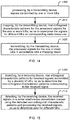
- the present disclosure provides in some embodiments a method for data transmission, including steps of: detecting, by a receiving device, non-orthogonal characteristic patterns for received signals transmitted by a plurality of UEs, so as to determine the non-orthogonal characteristic patterns corresponding to the received signal; and detecting, by the receiving device, the received signals in a serial interference cancellation manner using the detected non-orthogonal characteristic patterns, and processing the received signals, so as to determine data for different UEs.
- the step of detecting, by the receiving device, the non-orthogonal characteristic patterns for the received signals transmitted by the plurality of UEs includes: detecting, by the receiving device, the non-orthogonal characteristic patterns in a separate signal domain or a joint signal domain for the received signals.
- the method prior to the step of detecting, by the receiving device, the non-orthogonal characteristic pattern for the received signals transmitted by the plurality of the UEs, the method further includes: receiving through signaling, or blind-detecting, by the receiving device, the non-orthogonal characteristic patterns in the separate signal domain or the joint signal domain.
- the signal domain includes parts of or all of a power domain, a space domain and an encoding domain.
- the step of detecting, by the receiving device, the non-orthogonal characteristic patterns for the received signals transmitted by the plurality of UEs includes: in the case that non-orthogonal characteristic patterns in the power domain are used and the receiving device determines that the received signals transmitted by the plurality of UEs have an identical transmission time and an identical frequency resource but the UEs have different transmission power, determining, by the receiving device, that the non-orthogonal characteristic patterns contained in the received signals are the non-orthogonal characteristic patterns in the power domain.
- the receiving device determines that the received signals transmitted by the plurality of UEs have an identical transmission time and an identical frequency resource
- the signal transmitted by at least one UE corresponds to at least two transmission antenna ports and at least one reception antenna port corresponds to the signals transmitted by at least two UEs, determining, by the receiving device, that the non-orthogonal characteristic patterns contained in the received signals are the non-orthogonal characteristic patterns in the space domain.
- the receiving device determines that the received signals transmitted by the plurality of UEs have an identical transmission time and an identical frequency resource and have different encoding modes and different transmission delays, determining, by the receiving device, that the non-orthogonal characteristic patterns contained in the received signals are the non-orthogonal characteristic patterns in the encoding domain.
- the step of detecting, by the receiving device, the non-orthogonal characteristic patterns for the received signals transmitted by the plurality of UEs includes: in the case that the non-orthogonal characteristic patterns in a joint signal domain consisting of the power domain and the space domain are adopted, and the receiving device determines that the received signals transmitted by the plurality of UEs have an identical transmission time, an identical frequency resource and different transmission power.
- the signal transmitted by at least one UE corresponds to at least two transmission antenna ports and at least one reception antenna port corresponds to the signals transmitted by at least two UEs, determining, by the receiving device, that the non-orthogonal characteristic patterns contained in the received signals are the non-orthogonal characteristic patterns in the joint signal domain consisting of the power domain and the space domain.
- the receiving device determines that the received signals transmitted by the plurality of UEs have an identical transmission time, an identical frequency resource, different transmission power, different encoding modes and different transmission delays, determining, by the receiving device, that the non-orthogonal characteristic patterns contained in the received signals are the non-orthogonal characteristic patterns in the joint signal domain consisting of the power domain and the encoding domain.
- the receiving device determines that the received signals transmitted by the plurality of UEs have an identical transmission time, an identical frequency resource, different encoding modes and different transmission delays, the signal transmitted by at least one UE corresponding to at least two transmission antenna ports and at least one reception antenna port corresponding to the signals transmitted by at least two UEs, determining, by the receiving device, that the non-orthogonal characteristic patterns contained in the received signals are non-orthogonal characteristic patterns in the joint signal domain consisting of the space domain and the encoding domain.
- the receiving device determines that the received signals transmitted by the plurality of UEs have an identical transmission time, an identical frequency resource, different transmission power, different encoding modes and different transmission delays, the signal transmitted by at least one UE corresponding to at least two transmission antenna ports and at least one reception antenna port corresponding to the signals transmitted by at least two UEs, determining, by the receiving device, that the non-orthogonal characteristic patterns contained in the received signals are the non-orthogonal characteristic patterns in the joint signal domain consisting of the power domain, the space domain and the encoding domain.
- the present disclosure provides in some embodiments a transmitting device for data transmission, including: a first processing module configured to process signals transmitted by one or more UEs; a characteristic pattern mapping module configured to map non-orthogonal characteristic patterns for the processed signals for the one or more UEs, so as to superpose the signals for different UEs on corresponding radio resources; and a transmission module configured to transmit the processed signals for the one or more UEs in accordance with a mapping result.
- the characteristic pattern mapping module is configured to map the non-orthogonal characteristic patterns in a separate signal domain or a joint signal domain for the processed signals for the one or more UEs.
- the signal domain includes parts of or all of a power domain, a space domain and an encoding domain.
- the transmitting device is a network side device.
- the characteristic pattern mapping module is configured to allocate an identical transmission time and an identical frequency resource to the signals transmitted by the UEs and allocate transmission power to the signals transmitted by the UEs in accordance with the non-orthogonal characteristic patterns in the power domain. And a sum of the transmission power allocated to all the UEs is equal to total system-available power.
- the characteristic pattern mapping module is configured to allocate an identical transmission time and an identical frequency resource to the signals transmitted by the UEs and allocate at least two transmission antenna ports to the signal transmitted by at least one UE in accordance with the non-orthogonal characteristic patterns in the space domain. And at least one of the transmission antenna ports corresponds to the signals transmitted by at least two UEs.
- the characteristic pattern mapping module is configured to allocate an identical transmission time and an identical frequency resource to the signals transmitted by the UEs and allocate different encoding modes and different transmission delays to the signals transmitted by the one or more UEs in accordance with the non-orthogonal characteristic patterns in the encoding domain.
- the transmitting device is a network side device.
- the characteristic pattern mapping module is configured to allocate an identical transmission time and an identical frequency resource to the signals transmitted by the UEs, allocate transmission power to the signals transmitted by the UEs in accordance with the non-orthogonal characteristic pattern in the joint signal domain consisting of the power domain and the space domain, and allocate at least two transmission antenna ports to the signal transmitted by at least one UE, a sum of the transmission power allocated to all the UEs being equal to total system-available power, and the at least one of transmission antenna ports corresponding to the signals transmitted by at least two UEs.
- the characteristic pattern mapping module is configured to allocate an identical transmission time and an identical frequency resource to the signals transmitted by the UEs, allocate transmission power to the signals transmitted by the UEs in accordance with the non-orthogonal characteristic patterns in the joint signal domain consisting of the power domain and the encoding domain, and allocate different encoding modes and different transmission delays to the signals transmitted by the UEs, and a sum of the transmission power allocated to all the UEs being equal to total system-available power.
- the characteristic pattern mapping module is configured to allocate an identical transmission time and an identical frequency resource to the signals transmitted by the UEs, allocate at least two transmission antenna ports to the signal transmitted by at least one UE in accordance with the non-orthogonal characteristic patterns in the joint signal domain consisting of the space domain and the encoding domain, and allocate different encoding modes and different transmission delays to the signals transmitted by the UEs, and at least one of the transmission antenna ports corresponding to the signals for at least two UEs.
- the characteristic pattern mapping module is configured to allocate an identical transmission time and an identical frequency resource to the signals transmitted by the UEs, allocate transmission power to the UEs in accordance with the non-orthogonal characteristic patterns in the joint signal domain consisting of the power domain, the space domain and the encoding domain, allocate at least two transmission antenna ports to the signal transmitted by at least one UE, and allocate different encoding modes and different transmission delays to the signals transmitted by each of the UEs, a sum of the transmission power allocated to all the UEs being equal to total system-available power, and at least one of the transmission antenna ports corresponding to the signals transmitted by at least two UEs.
- the transmitting device is a UE.
- the characteristic pattern mapping module is configured to determine a transmission time and a frequency resource for its own signal, and determine transmission power for its own signal in accordance with its own non-orthogonal characteristic pattern in the power domain, and the transmission time and the frequency resource for the signal being identical to those for a signal transmitted by another UE.
- the characteristic pattern mapping module is configured to determine a transmission time and a frequency resource for its own signal, and determine a transmission antenna port corresponding to its own signal in accordance with its own non-orthogonal characteristic pattern in the space domain, and the transmission time and the frequency resource for the signal being identical to those for a signal transmitted by another UE.
- the characteristic pattern mapping module is configured to determine a transmission time and a frequency resource for its own signal, and determine an encoding mode and a transmission delay for its own signal in accordance with its own non-orthogonal characteristic pattern in the encoding domain, the transmission time and the frequency resource for the signal transmitted by the transmitting device being identical to those for a signal transmitted by another UE, the encoding mode for the signal transmitted by the transmitting device being different from that for the signal transmitted by the other UE, and the transmission delay for the signal transmitted by the transmitting device being different from that for the signal transmitted by the other UE.
- the transmitting device is a UE.
- the characteristic pattern mapping module is configured to determine a transmission time and a frequency resource for its own signal, and determine transmission power and a corresponding transmission antenna port for its own signal in accordance with its own non-orthogonal characteristic pattern in the joint signal domain consisting of the power domain and the space domain, and the transmission time and the frequency resource for the signal transmitted by the transmitting device are identical to those for a signal transmitted by another UE.
- the characteristic pattern mapping module is configured to determine a transmission time and a frequency resource for its own signal, and determine transmission power, an encoding mode and a transmission delay for its own signal in accordance with its own non-orthogonal characteristic pattern in the joint signal domain consisting of the power domain and the encoding domain, the transmission time and the frequency resource for the signal being identical to those for a signal transmitted by another UE, the encoding mode for the signal transmitted by the transmitting device being different from that for the signal transmitted by the other UE, and the transmission delay for the signal transmitted by the transmitting device being different from that for the signal transmitted by the other UE.
- the characteristic pattern mapping module is configured to determine a transmission time and a frequency resource for its own signal, and determine a transmission antenna port, an encoding mode and a transmission delay for its own signal in accordance with its own non-orthogonal characteristic pattern in the joint signal domain consisting of the space domain and the encoding domain, the transmission time and the frequency resource for the signal transmitted by the transmitting device being identical to those for a signal transmitted by another UE, the encoding mode for the signal transmitted by the transmitting device being different from that for the signal transmitted by the other UE, and the transmission delay for the signal transmitted by the transmitting device being different from that for the signal transmitted by the other UE.
- the characteristic pattern mapping module is configured to determine a transmission time and a frequency resource for its own signal, and determine a transmission antenna port, transmission power, an encoding mode and a transmission delay for its own signal in accordance with its own non-orthogonal characteristic pattern in the joint signal domain consisting of the power domain, the space domain and the encoding domain, the transmission time and the frequency resource for the signal transmitted by the transmitting device being identical to those for a signal transmitted by another UE, the encoding mode for the signal transmitted by the transmitting device being different from that for the signal transmitted by the other UE, and the transmission delay for the signal transmitted by the transmitting device being different from that for the signal transmitted by the other UE.
- a transmitting device for data transmission including: a processor; a memory connected to the processor via a bus interface and configured to store a program and data used for the operation of the processor; and a transceiver connected to the processor and the memory via the bus interface, and configured to transmit and receive data under the control of the processor.
- the processor is configured to call and execute the program and data stored in the memory, so as to realize the following steps including: processing signals transmitted by one or more User Equipments (UEs); mapping non-orthogonal characteristic patterns for the processed signals for the one or more UEs, so as to superpose the signals for different UEs on corresponding radio resources; and transmitting the processed signals for the one or more UEs in accordance with a mapping result.
- UEs User Equipments
- the present disclosure provides in some embodiments a receiving device for data transmission, including: a characteristic pattern detection module configured to detect non-orthogonal characteristic patterns for received signals transmitted by a plurality of UEs, so as to determine the non-orthogonal characteristic patterns corresponding to the received signal; and a second processing module configured to detect the received signals in a serial interference cancellation manner using the detected non-orthogonal characteristic patterns, and process the received signals, so as to determine data for different UEs.
- a characteristic pattern detection module configured to detect non-orthogonal characteristic patterns for received signals transmitted by a plurality of UEs, so as to determine the non-orthogonal characteristic patterns corresponding to the received signal
- a second processing module configured to detect the received signals in a serial interference cancellation manner using the detected non-orthogonal characteristic patterns, and process the received signals, so as to determine data for different UEs.
- the characteristic pattern detection module is configured to detect the non-orthogonal characteristic patterns in a separate signal domain or a joint signal domain for the received signals.
- the characteristic pattern detection module is further configured to receive through signaling, or blind-detecting the non-orthogonal characteristic patterns in the separate signal domain or the joint signal domain.
- the signal domain includes parts of or all of a power domain, a space domain and an encoding domain.
- the characteristic pattern detection module is configured to: in the case that non-orthogonal characteristic patterns in the power domain are used, the received signals transmitted by the plurality of UEs have an identical transmission time and an identical frequency resource but the UEs have different transmission power, determine that the non-orthogonal characteristic patterns contained in the received signals are the non-orthogonal characteristic patterns in the power domain; or in the case that non-orthogonal characteristic patterns in the space domain are used, the received signals transmitted by the plurality of UEs have an identical transmission time and an identical frequency resource, the signal transmitted by at least one UE corresponds to at least two transmission antenna ports and at least one reception antenna port corresponds to the signals transmitted by at least two UEs, determine that the non-orthogonal characteristic patterns contained in the received signals are the non-orthogonal characteristic patterns in the space domain; or in the case that the non-orthogonal characteristic patterns in the encoding domain are adopted and the received signals transmitted by the plurality of UEs have an identical transmission time and an identical frequency resource and
- the characteristic pattern detection module is configured to: in the case that the non-orthogonal characteristic patterns in a joint signal domain consisting of the power domain and the space domain are adopted, the received signals transmitted by the plurality of UEs have an identical transmission time, an identical frequency resource and different transmission power, the signal transmitted by at least one UE corresponding to at least two transmission antenna ports and at least one reception antenna port corresponds to the signals transmitted by at least two UEs, determine that the non-orthogonal characteristic patterns contained in the received signals are the non-orthogonal characteristic patterns in the joint signal domain consisting of the power domain and the space domain; or in the case that the non-orthogonal characteristic patterns in a joint signal domain consisting of the power domain and the encoding domain are adopted, and the received signals transmitted by the plurality of UEs have an identical transmission time, an identical frequency resource, different transmission power, different encoding modes and different transmission delays, determine that the non-orthogonal characteristic patterns contained in the received signals are the non-orthogonal characteristic patterns in the
- the present disclosure provides in some embodiments a receiving device for data transmission, including: a processor; a memory connected to the processor via a bus interface, and configured to store a program and data desired for the operation of the processor; and a transceiver connected to the processor and the memory via a bus interface, and configured to transmit and receive data under the control of the processor.
- the processor is configured to call and execute the program and data stored in the memory, so as to realize the following steps including: detecting non-orthogonal characteristic patterns for received signals transmitted by a plurality of User Equipments (UEs), so as to determine the non-orthogonal characteristic patterns corresponding to the received signal; and detecting the received signals in a Serial Interference Cancellation (SIC) manner using the detected non-orthogonal characteristic patterns, and processing the received signals, so as to determine data for different UEs.
- UEs User Equipments
- SIC Serial Interference Cancellation
- the present disclosure provides in some embodiments a data transmission system, including: a transmitting device configured to process signals transmitted by one or more UEs, map non-orthogonal characteristic patterns for the processed signals for the one or more UEs so as to superpose the signals for different UEs on corresponding radio resources, and transmit the processed signals for the one or more UEs in accordance with a mapping result; and a receiving device configured to detect non-orthogonal characteristic patterns for received signals transmitted by a plurality of UEs, so as to determine the non-orthogonal characteristic patterns corresponding to the received signal, and detect the received signals in a serial interference cancellation manner using the detected non-orthogonal characteristic patterns, and process the received signals, so as to determine data for different UEs.
- the transmitting device may process the signals transmitted by one or more UEs, map the non-orthogonal characteristic patterns for the processed signals for the one or more UEs so as to superpose the signals for different UEs on the corresponding radio resources, and transmit the processed signals for the one or more UEs in accordance with a mapping result.
- the signals transmitted by the one or more UEs it is able for the signals transmitted by the one or more UEs to be superposed non-orthogonally on the radio resources, thereby to achieve the data transmission in a non-orthogonal multiple access manner, and improve the radio resource utilization.
- Such words as “one” or “one of” are merely used to represent the existence of at least one member, rather than to limit the number thereof.
- Such words as “connect” or “connected to” may include electrical connection, direct or indirect, rather than to be limited to physical or mechanical connection.
- Such words as “on”, “under”, “left” and “right” are merely used to represent relative position relationship, and when an absolute position of the object is changed, the relative position relationship will be changed too.
- a transmitting device may process signals transmitted by one or more UEs, map non-orthogonal characteristic patterns for the processed signals for the one or more UEs so as to superpose the signals transmitted by different UEs on corresponding radio resources, and transmit the processed signals for the one or more UEs in accordance with a mapping result.
- the signals transmitted by the one or more UEs it is able for the signals transmitted by the one or more UEs to be superposed non-orthogonally on the radio resources, thereby to achieve the data transmission in a non-orthogonal multiple access manner, and improve the radio resource utilization.
- the above-mentioned non-orthogonal characteristic patterns refer to superposing patterns of signals having certain characteristics on identical time-domain and frequency-domain resources in such a manner that the signals cannot be divided orthogonally on the same time-domain and frequency-domain resources.
- the above-mentioned non-orthogonal characteristic patterns refer to transmitting, on the same time-domain and frequency-domain resources, signals for a plurality of users superposed in accordance with their non-orthogonal characteristic patterns, where the signal for each user corresponds to one of the non-orthogonal characteristic patterns.
- the resources of an existing orthogonal multiple access system may be multiplexed by the plurality of users or the signals for the plurality of users may be directly multiplexed, so as to achieve the non-orthogonal multiple access transmission.
- the transmitting device in the case of uplink transmission, is a UE and a receiving device is a network side device.
- the transmitting device is a network side device and the receiving device is a UE.
- the network side device may be a base station (e.g., macro base station, micro base station or Femtocell), or a relay node (RN) device, or any other network side device that is already known or that may come into being in the future.
- RN relay node
- the present disclosure provides in the first embodiment a system for data transmission, which includes transmitting device 10 and a receiving device 20.
- the transmitting device 10 is configured to process signals transmitted by one or more UEs, map non-orthogonal characteristic patterns for the processed signals transmitted by the one or more UEs so as to superpose the signals for different UEs on corresponding radio resources, and transmit the processed signals for the one or more UEs in accordance with a mapping result.
- the receiving device 20 is configured to detect non-orthogonal characteristic patterns for received signals transmitted by a plurality of UEs so as to determine the non-orthogonal characteristic patterns corresponding to the received signal, detect the received signals in a serial interference cancellation (SIC) manner using the detected non-orthogonal characteristic patterns, and process the received signals, so as to determine data for different UEs.
- SIC serial interference cancellation
- the transmitting device maps the non-orthogonal characteristic patterns for the processed signals transmitted by the one or more UEs, it may map the non-orthogonal characteristic patterns in a separate signal domain or a joint signal domain for the processed signals for the one or more UEs.
- the receiving device may detect the non-orthogonal characteristic patterns in the separate signal domain or the joint signal domain for the received signals.
- the signal domain includes parts of or all of a power domain, a space domain and an encoding domain.
- the transmitting device in the case of the uplink transmission, is a UE and the receiving device is a network side device.
- the transmitting device is a network side device and the receiving device is a UE. More details will be given as follows.
- Case 1 downlink transmission where the transmitting device is a network side device and the receiving device is a UE.
- the transmitting device maps the non-orthogonal characteristic patterns for the processed signals transmitted by the one or more UEs, it may allocate an identical transmission time and an identical frequency resource to the signals transmitted by the UEs and allocate transmission power to the signals transmitted by the UEs in accordance with the non-orthogonal characteristic patterns in the power domain.
- a sum of the transmission power allocated to all the UEs is equal to total system-available power, so as to differentiate the UEs.
- the receiving device determines that the received signals for the UEs have an identical transmission time, an identical frequency resource and different transmission power, it may determine that the non-orthogonal characteristic patterns contained in the received signals are the non-orthogonal characteristic patterns in the power domain.
- all the UEs in the embodiments of the present disclosure are located within an identical region, for example, an identical cell.
- the transmission power may be allocated to the signals transmitted by the UEs, and the sum of the transmission power allocated to all the UEs is equal to the total system-available power.
- the transmission power may be allocated to the signals transmitted by the UEs superposed on an identical time-frequency resource in accordance with the maximum available transmission power on the time-frequency resource.
- the transmission power ⁇ P may be allocated to a UE1 and the transmission power (1- ⁇ )P may be allocated to a UE2 ( ⁇ is a power allocation factor, and 0 ⁇ 1).
- the transmitting device maps the non-orthogonal characteristic patterns for the processed signals for the UEs, it may allocate an identical transmission time and an identical frequency resource to the signals for the UEs and allocate at least two transmission antenna ports to the signal for at least one UE in accordance with the non-orthogonal characteristic patterns in the space domain.
- At least one of the transmission antenna ports corresponds to the signals for at least two UEs, so as to differentiate the UEs or data streams for an identical UE.
- each signal may be transmitted via a corresponding transmission antenna. For example, in the case that a certain signal corresponds to two antennae, it may be transmitted via the two antennae.
- the receiving device determines that the received signals for the UEs have an identical transmission time and an identical frequency resource, the signal for at least one UE corresponds to at least two transmission antenna ports and at least one of the transmission antenna ports corresponds to the signals for at least two UEs, it may determine that the non-orthogonal characteristic patterns contained in the received signals are non-orthogonal characteristic patterns in the space domain.
- At least two transmission antenna ports may be allocated to the signal for at least one UE, and at least one transmission antenna port corresponds to the signals for at least two UEs.
- Each antenna port is a identifiable (recognizable) baseband logic unit, and each baseband logic unit may correspond to one physical antenna or a combination of a plurality of physical antennae.
- a data stream S 1 for the UE1 may be transmitted via a first antenna
- a data stream S 2 for the UE2 may be transmitted via a second antenna.
- more than two data streams may be transmitted by the base station, e.g., an additional data stream S 3 may be transmitted to the UE2.
- the data stream S 1 for the UE1 may be transmitted via an antenna 1
- the data stream S 2 for the UE2 may be transmitted via the antenna 1 too
- the data stream S 3 for the UE2 may be transmitted via an antenna 2.
- the antenna 1 corresponds to the data stream S 1 for the UE1 and the data stream S 2 for the UE2
- the antenna 2 corresponds to the data stream S 3 for the UE2.
- the data stream S 1 for the UE1 may be transmitted simultaneously via the antennae 1 and 2, the data stream S 2 for the UE2 may be transmitted via the antenna 1, and the data stream S 3 for the UE2 may be transmitted via the antenna 2.
- the antenna 1 corresponds to the data stream S 1 for the UE1 and the data stream S 2 for the UE2
- the antenna 2 corresponds to the data stream S 1 for the UE1 and the data stream S 3 for the UE2.
- it may transmit more information in the space-domain non-orthogonal transmission mode with spatial encoding, so it is able to improve the detection performance of the corresponding receiving device.
- the transmitting device maps the non-orthogonal characteristic patterns for the processed signals for the UEs, it may allocate an identical transmission time and an identical frequency resource to the signals for the UEs and allocate different encoding modes and different transmission delays to the signals for the one or more UEs in accordance with the non-orthogonal characteristic patterns in the encoding domain, so as to differentiate the UEs.
- the receiving device determines that the received signals for the UEs have an identical transmission time, an identical frequency resource, different encoding modes and different transmission delays, it may determine that the non-orthogonal characteristic patterns contained in the receiving signals are the non-orthogonal characteristic patterns in the encoding domain.
- the transmission of the encoded data stream for the UE2 may be delayed by t 1 as compared with the transmission of the encoded data stream for the UE1, and the transmission of the encoded data stream for a UE3 may be delayed by t 2 as compared with the transmission of the encoded data stream for the UE2.
- the non-orthogonal characteristic pattern is a non-orthogonal characteristic pattern in a joint signal domain consisting of the power domain and the space domain.
- the transmitting device maps the non-orthogonal characteristic patterns for the processed signals for the UEs, it may allocate an identical transmission time and an identical frequency resource to the signals for the UEs, allocate transmission power to the signals for the UEs in accordance with the non-orthogonal characteristic pattern in the joint signal domain consisting of the power domain and the space domain, and allocate at least two transmission antenna ports to the signal for at least one UE.
- a sum of the transmission power allocated to all the UEs is equal to total system-available power, and the at least one transmission antenna port corresponds to the signals for at least two UEs, so as to differentiate the UEs.
- the receiving device determines that the received signals for the UEs have an identical transmission time, an identical frequency resource and different transmission power, the signal for at least one UE corresponds to at least two transmission antenna ports and at least one transmission antenna port corresponds to the signals for at least two UEs, the receiving device may determine that the non-orthogonal characteristic patterns contained in the received signals are the non-orthogonal characteristic patterns in the joint signal domain consisting of the power domain and the space domain.
- the non-orthogonal characteristic pattern is a non-orthogonal characteristic pattern in a joint signal domain consisting of the power domain and the encoding domain.
- the transmitting device maps the non-orthogonal characteristic patterns for the processed signals for the UEs, it may allocate an identical transmission time and an identical frequency resource to the signals for the UEs, allocate transmission power to the signals for the UEs in accordance with the non-orthogonal characteristic patterns in the joint signal domain consisting of the power domain and the encoding domain, and allocate different encoding modes and different transmission delays to the signals for the UEs, so as to differentiate the UEs.
- a sum of the transmission power allocated to all the UEs is equal to total system-available power.
- the receiving device may determine that the non-orthogonal characteristic patterns contained in the received signals are the non-orthogonal characteristic patterns in the joint signal domain consisting of the power domain and the encoding domain.
- the non-orthogonal characteristic pattern is a non-orthogonal characteristic pattern in a joint signal domain consisting of the space domain and the encoding domain.
- the transmitting device maps the non-orthogonal characteristic patterns for the processed signals for the UEs, it may allocate an identical transmission time and an identical frequency resource to the signals for the UEs, allocate at least two transmission antenna ports to the signal for at least one UE in accordance with the non-orthogonal characteristic patterns in the joint signal domain consisting of the space domain and the encoding domain, and allocate different encoding modes and different transmission delays to the signals for the UEs, so as to differentiate the UEs. At least one of the transmission antenna ports corresponds to the signals for at least two UEs.
- the receiving device determines that the received signals for the UEs have an identical transmission time, an identical frequency resource, different encoding modes and different transmission delays, the signal for at least one UE corresponds to at least two transmission antenna ports and at least one transmission antenna port corresponds to the signals for at least two UEs, the receiving device may determine that the non-orthogonal characteristic patterns contained in the received signals are the non-orthogonal characteristic patterns in the joint signal domain consisting of the space domain and the encoding domain.
- the non-orthogonal characteristic pattern is a non-orthogonal characteristic pattern in a joint signal domain consisting of the power domain, the space domain and the encoding domain.
- the transmitting device maps the non-orthogonal characteristic patterns for the processed signals for the UEs, it may allocate an identical transmission time and an identical frequency resource to the signals for the UEs, allocate transmission power to the UEs in accordance with the non-orthogonal characteristic patterns in the joint signal domain consisting of the power domain, the space domain and the encoding domain, allocate at least two transmission antenna ports to the signal for at least one UE, and allocate different encoding modes and different transmission delays to the signals for the UEs, so as to differentiate the UEs.
- a sum of the transmission power allocated to all the UEs is equal to total system-available power, and at least one of the transmission antenna ports corresponds to the signals for at least two UEs.
- the receiving device determines that the received signals for the UEs have an identical transmission time, an identical frequency resource, different transmission power, different encoding modes and different transmission delays, the signal for at least one UE corresponds to at least two transmission antenna ports and at least one transmission antenna port corresponds to the signals for at least two UEs, the receiving device may determine that the non-orthogonal characteristic patterns contained in the received signals are that the non-orthogonal characteristic patterns in the joint signal domain consisting of the power domain, the space domain and the encoding domain.
- Case 2 uplink transmission, where the transmitting device is a UE, and the receiving device is a network side device.
- the transmitting device maps the non-orthogonal characteristic pattern for the processed signal for one UE, it may determine a transmission time and a frequency resource for its own signal, and determine transmission power for its own signal in accordance with its own non-orthogonal characteristic pattern in the power domain.
- the transmission time and the frequency resource for the signal are identical to those for a signal for another UE.
- the receiving device may determine that the non-orthogonal characteristic patterns contained in the received signals are the non-orthogonal characteristic patterns in the power domain.
- all the UEs in the embodiments of the present disclosure are located within an identical region, e.g., an identical cell.
- the transmitting device maps the non-orthogonal characteristic pattern for the processed signal for one UE, it may determine a transmission time and a frequency resource for its own signal, and determine a transmission antenna port corresponding to its own signal in accordance with its own non-orthogonal characteristic pattern in the space domain.
- the transmission time and the frequency resource for the signal are identical to those for a signal for another UE.
- the receiving device determines that the received signals for the UEs have an identical transmission time and an identical frequency resource, the signal for at least one UE corresponds to at least two transmission antenna ports and at least one of the transmission antenna ports corresponds to the signals for at least two UEs, it may determine that the non-orthogonal characteristic patterns contained in the received signals are non-orthogonal characteristic patterns in the space domain.
- the merely one data stream S 1 is to be transmitted by the UE via two antennae, it may be transmitted via the antenna 1 and the antenna 2, and in the case that two data streams S 1 and S 2 are to be transmitted, the data stream S 1 may generally be transmitted via the antenna 1 and the data stream S 2 may be transmitted via the antenna 2.
- the transmitting device maps the non-orthogonal characteristic pattern for the processed signal for one UE, it may determine a transmission time and a frequency resource for its own signal, and determine an encoding mode and a transmission delay for its own signal in accordance with its own non-orthogonal characteristic pattern in the encoding domain.
- the transmission time and the frequency resource for the signal are identical to those for a signal for another UE, the encoding mode for the signal for the transmitting device is different from that for the signal for the other UE, and the transmission delay for the signal for the transmitting device is different from that for the signal for the other UE.
- the receiving device determines that the received signals for the UEs have an identical transmission time, an identical frequency resource, different encoding modes and different transmission delays, it may determine that the non-orthogonal characteristic patterns contained in the receiving signals are the non-orthogonal characteristic patterns in the encoding domain.
- the transmitting device maps the non-orthogonal characteristic pattern for the processed signal for one UE, it may determine a transmission time and a frequency resource for its own signal, and determine transmission power and a corresponding transmission antenna port for its own signal in accordance with its own non-orthogonal characteristic pattern in the joint signal domain consisting of the power domain and the space domain.
- the transmission time and the frequency resource for the signal are identical to those for a signal for another UE.
- the receiving device determines that the received signals for the UEs have an identical transmission time and an identical frequency resource, the signals for at least two UEs have different transmission power, the signal for at least one UE corresponds to at least two transmission antenna ports and at least one transmission antenna port corresponds to the signals for at least two UEs, the receiving device may determine that the non-orthogonal characteristic patterns contained in the received signals are the non-orthogonal characteristic patterns in the joint signal domain consisting of the power domain and the space domain.
- the transmitting device maps the non-orthogonal characteristic pattern for the processed signal for one UE, it may determine a transmission time and a frequency resource for its own signal, and determine transmission power, an encoding mode and a transmission delay for its own signal in accordance with its own non-orthogonal characteristic pattern in the joint signal domain consisting of the power domain and the encoding domain.
- the transmission time and the frequency resource for the signal for the transmitting device are identical to those for a signal for another UE, the encoding mode for the signal for the transmitting device is different from that for the signal for the other UE, and the transmission delay for the signal for the transmitting device is different from that for the signal for the other UE.
- the receiving device determines that the received signals for the UEs have an identical transmission time and an identical frequency resource, and the signals for at least two UEs have different transmission power, different encoding modes and different transmission delays, the receiving device may determine that the non-orthogonal characteristic patterns contained in the received signals are the non-orthogonal characteristic patterns in the joint signal domain consisting of the power domain and the encoding domain.
- the transmitting device maps the non-orthogonal characteristic pattern for the processed signal for one UE, it may determine a transmission time and a frequency resource for its own signal, and determine a transmission antenna port, an encoding mode and a transmission delay for its own signal in accordance with its own non-orthogonal characteristic pattern in the joint signal domain consisting of the space domain and the encoding domain.
- the transmission time and the frequency resource for the signal for the transmitting device are identical to those for a signal for another UE, the encoding mode for the signal for the transmitting device is different from that for the signal for the other UE, and the transmission delay for the signal for the transmitting device is different from that for the signal for the other UE.
- the receiving device determines that the received signals for the plurality of UEs have an identical transmission time and an identical frequency resource, the signals for at least two UEs have different encoding modes and different transmission delays, the signal for at least one UE corresponds to at least two transmission antenna ports and at least one transmission antenna port corresponds to the signals for at least two UEs, the receiving device may determine that the non-orthogonal characteristic patterns contained in the received signals are the non-orthogonal characteristic patterns in the joint signal domain consisting of the space domain and the encoding domain.
- the non-orthogonal characteristic pattern is a non-orthogonal characteristic pattern in a joint signal domain consisting of the power domain, the space domain and the encoding domain.
- the transmitting device maps the non-orthogonal characteristic pattern for the processed signal for one UE, it may determine a transmission time and a frequency resource for its own signal, and determine a transmission antenna port, transmission power, an encoding mode and a transmission delay for its own signal in accordance with its own non-orthogonal characteristic pattern in the joint signal domain consisting of the power domain, the space domain and the encoding domain.
- the transmission time and the frequency resource for the signal for the transmitting device are identical to those for a signal for another UE, the encoding mode for the signal for the transmitting device is different from that for the signal for the other UE, and the transmission delay for the signal for the transmitting device is different from that for the signal for the other UE, so as to differentiate the plurality of UEs.
- the receiving device determines that the received signals for the UEs have an identical transmission time and an identical frequency resource, the signals for at least two UEs have different transmission power, different encoding modes and different transmission delays, the signal for at least one UE corresponds to at least two transmission antenna ports and at least one transmission antenna port corresponds to the signals for at least two UEs, the receiving device may determine that the non-orthogonal characteristic patterns contained in the received signals are that the non-orthogonal characteristic patterns in the joint signal domain consisting of the power domain, the space domain and the encoding domain.
- the detection signals for the UEs may be separated level by level, and the co-channel interference may be canceled in time, so as to improve the detection accuracy.
- the UEs may be differentiated from each other on the basis of the non-orthogonal characteristic patterns of a plurality of signal domains, and at the receiving device, on the basis of characteristic structures of users' patterns, the multiuser detection may be achieved in a SIC manner.
- a technology corresponding to the method, the system and the device for data transmission is called as Pattern Division Non-orthogonal Multiple Access (Pattern Division Multiple Access (PDMA) for short) technology.
- PDMA Pattern Division Non-orthogonal Multiple Access
- the PDMA technology may be applied to both an uplink and a downlink of a communication system.
- a base station includes a transmitting device and a receiving device.
- a signal for the downlink may be modulated and transmitted by the transmitting device, and during the reception, a signal for the uplink may be received and detected by the receiving device.
- the signals for the UEs may be differentiated from each other at the transmitting device using the non-orthogonal characteristic patterns in the separate signal domain or the joint signal domain consisting of the power domain, the space domain and the encoding domain, and the signals for the UEs maybe effectively detected at the receiving device in a SIC manner.
- FDMA frequency division multiple access
- TDMA time division multiple access
- CDMA code division multiple access
- OFDMA orthogonal frequency division multiple access
- the base station may transmit the signals via multiple antennae, and each UE may receive the signal via a single antenna.
- FIG. 3A shows the downlink for the PDMA system.
- the transmitting device may process (e.g., encode and modulate) the signals for the plurality of UEs, and then map the non-orthogonal characteristic patterns, so as to achieve the non-orthogonal superposition of the signals for the UEs in the time-frequency domain.
- the receiving device e.g., a UE
- the receiving device may detect and preliminarily identify the non-orthogonal characteristic patterns for the received and superposed signals for the UEs, and then detect the valid UEs through processing the preliminarily-identified signals in a SIC manner.
- each UE receives the signal via multiple antennae
- the operation procedures for the transmitting device and the receiving device are similar to the operation procedures where the signal is received via a single antenna. The only difference lies in that the signal may be received via multiple antennae.
- the UE may transmit the signal via a single antenna, and the base station may receive the signals via multiple antennae.
- FIG. 3B shows an uplink for the PDMA system.
- each UE may encode and modulate its own signal, and then the transmitting device may map the non-orthogonal characteristic patterns, so as to achieve the non-orthogonal superposition of the signals for the UEs in an identical time-frequency domain.
- the base station may detect and preliminarily identify the non-orthogonal characteristic patterns for the received and superposed signals for the UEs, and then detect the UEs through processing the preliminarily-identified signals in a SIC manner.
- each UE transmits the signal via multiple antennae
- the operation procedures for the transmitting device and the receiving device are similar to the operation procedures where the signal is transmitted via a single antenna. The only difference lies in that the signal may be transmitted via multiple antennae.
- the non-orthogonal characteristic pattern may be a non-orthogonal characteristic pattern in a separate signal domain, e.g., a non-orthogonal characteristic pattern in the power domain, a non-orthogonal characteristic pattern in the space domain or a non-orthogonal characteristic pattern in the encoding domain; or a non-orthogonal characteristic pattern in a joint signal domain, e.g., a non-orthogonal characteristic pattern in a joint signal domain consisting of the power domain and the space domain, non-orthogonal characteristic pattern in a joint signal domain consisting of the power domain and the encoding domain, a non-orthogonal characteristic pattern in a joint signal domain consisting of the space domain and the encoding domain, or a non-orthogonal characteristic pattern in a joint signal domain consisting of the power domain, the space domain and the encoding domain.
- a non-orthogonal characteristic pattern in a separate signal domain e.g., a non-orthogonal
- the power may be allocated in accordance with channel quality of the UE, and theoretically all the time-frequency resources of a system may be occupied by each UE.
- an auxiliary user scheduling algorithm is provided, and at the receiving device, the SIC is performed, so as to increase the system capacity and the capacity for each UE (especially the capacity for the UE at a cell edge).
- FIG. 5A and FIG. 5B each shows the mapping procedures of the non-orthogonal characteristic patterns in the power domain on the uplink and the downlink respectively.
- Each mapping procedure includes two basic procedures, i.e., the allocation of the time-frequency resources and the allocation of the power. Although shown in FIG. 5A and FIG. 5B , the order of these two basic procedures is not particularly defined herein, which can be swapped up.
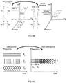
- FIG. 4A shows the difference in the occupation of the radio resources between the non-orthogonal mode and the orthogonal mode.
- different frequency resources may be adopted by different UEs.
- an identical frequency resource and different power may be adopted by different UEs, so as to differentiate the UEs from one another.
- the non-orthogonal characteristic pattern in the power domain includes power vectors corresponding to respective time-frequency resource blocks for the UEs.
- the signals for the UEs may be spatially encoded in a SIC manner, so as to effectively divide the signals for the UEs after the SIC detection, thereby to achieve the multiple access.
- FIG. 6A and FIG. 6B each shows the mapping procedures of the non-orthogonal characteristic patterns in the space domain on the uplink and the downlink respectively.
- Each mapping procedure includes two basic procedures, i.e., the allocation of the time-frequency resources and the spatial encoding. Although shown in FIG. 6A and FIG. 6B , the order of these two basic procedures is not particularly defined herein, which can be swapped up.
- FIG. 4B shows the difference in the occupation of the radio resources between the non-orthogonal mode without spatial encoding and the non-orthogonal mode with spatial encoding.
- the signal for the UE1 may merely be transmitted via the antenna 1, and the signal for the UE2 may be transmitted via the antennae 1 and 2, so it is very difficult to simultaneously detect the signals for the UE1 and the UE2 merely through the antenna 1.
- the signal for the UE1 may be simultaneously transmitted via the antennae 1 and 2, and the signals for multiple UEs may be superposed on each antenna.
- the non-orthogonal characteristic pattern in the space domain is a spatial encoding matrix for each UE in different antennae arrays.
- the data streams for the UEs may be encoded and then delayed, i.e., multi-stream superposition may be performed on the data streams.
- a structure similar to a channel encoding structure may be established between the data for the UEs, and then the structure may be optimized on the basis of a channel encoding theory.
- FIG. 7A and FIG. 7B each shows the mapping procedures of the non-orthogonal characteristic patterns in the encoding domain on the uplink and the downlink respectively.
- Each mapping procedure includes three basic procedures, i.e., copying, interleaving and delaying. The copying and interleaving procedures just refer to the data encoding procedure.
- the order of the data encoding procedure and the delaying procedure is not particularly defined herein, which can be swapped up.
- FIG. 4C shows the difference in the occupation of the radio resources between non-orthogonal mode and the orthogonal mode.
- different frequency resources may be adopted by different UEs.
- an identical frequency resource different encoding modes and different transmission delays may be adopted by different UEs, so as to differentiate the UEs from one another.
- the non-orthogonal characteristic pattern in the encoding domain refers to an encoding sequence and a corresponding transmission delay for each UE.
- FIG. 8A and FIG. 8B each shows the mapping procedures of the non-orthogonal characteristic patterns in the joint signal domain consisting of the power domain and the space domain on the uplink and the downlink respectively
- FIG. 9A and FIG. 9B each shows the mapping procedures of the non-orthogonal characteristic patterns in the joint signal domain consisting of the power domain and the encoding domain on the uplink and the downlink respectively.
- the mapping procedures of the non-orthogonal characteristic patterns in the other joint signal domains may be easily deducible and thus will not be particularly defined herein. Although shown in the drawings, the order of the basic procedures of each mapping procedure is not particularly defined herein.
- FIG. 4D shows the superposition of the signals for the UEs in the power domain and the space domain.
- An identical time-frequency resource may be adopted by different UEs, but these UEs may be differentiated from one another in terms of the power and the spatial encoding.
- the non-orthogonal characteristic pattern in the joint signal domain consisting of the power domain and the space domain is a combination of the non-orthogonal characteristic pattern in the power domain and the non-orthogonal characteristic pattern in the space domain.
- the non-orthogonal mode ten symbols may be transmitted via each data block, while in the orthogonal mode, merely nine symbols may be transmitted via each data block.
- the non-orthogonal mode it is able for the non-orthogonal mode to improve the spectrum utilization and the diversity (to reduce an error rate).
- the other non-orthogonal characteristic patterns may be similar to those mentioned above, and thus will not be particularly defined herein.
- the PDMA technology has been described hereinbefore mainly taking the power domain, the space domain and the encoding domain as an example.
- the non-orthogonal characteristic pattern in other potential signal domains may also be used.
- the non-orthogonal characteristic pattern at the transmitting device may be designed in such a manner as to facilitate the SIC detection at the receiving device, so as to improve the system performance and reduce the system complexity.
- the mapping procedure at the transmitting device may be used to effectively divide the user information, and the patterns may be differentiated from one another at the receiving device.
- the effective SIC may be performed on the selected pattern(s), so as to achieve the multiuse data transmission. Neither of the above can exist effectively without the other.
- the data transmission system in the embodiments of the present disclosure may be applied to a 3 rd -Generation (3G) mobile communication system on the basis of CDMA, or a 4 th -Generation (4G) mobile communication system on the basis of OFDMA.
- 3G 3 rd -Generation
- 4G 4 th -Generation
- a superposition technology for the existing mobile communication system may be adopted, so as to further improve the system capacity and the spectrum utilization.
- the data transmission system in the embodiments of the present disclosure may also be applied to a future 5 th -Generation (5G) mobile communication system, so as to meet the requirement on the capacity.
- the PDMA technology in the embodiments of the present disclosure may be adapted to various application scenarios for a 5 th -Generation system.
- the PDMA technology may be used to overcome a near-far effect, and improve the coverage performance at a cell edge.
- the PDMA technology may be dynamically adapted to a change in the network structure, so as to flexibly transmit the signals for the UEs.
- the PDMA technology may be used to inhibit the co-channel interference from a variety of sources, reduce the power consumption and improve the spectrum utilization.
- the PDMA technology may be used to double the number of the uplink access users.
- the PDMA technology may be used to perform redundancy transmission, so as to improve the reliability of the data transmission.
- the characteristic pattern used in the PDMA technology refers to the non-orthogonal division of the pattern in several signal domains (for example, the power domain, the space domain and the encoding domain) with respect to UE's attributes, rather than the orthogonal division on the basis of the time-frequency radio resources. Accordingly, it is unnecessary to strictly limit the number of the radio resources, thereby to remarkably increase the system capacity and improve the adaptability to the dynamic scenarios.
- the present disclosure provides in the second embodiment a transmitting device in the system for data transmission, which includes: a first processing module 1000 configured to process signals for one or more UEs; a characteristic pattern mapping module 1010 configured to map non-orthogonal characteristic patterns for the processed signals for the one or more UEs, so as to superpose the signals for different UEs on corresponding radio resources; and a transmission module 1020 configured to transmit the processed signals for the one or more UEs in accordance with a mapping result.
- a first processing module 1000 configured to process signals for one or more UEs
- a characteristic pattern mapping module 1010 configured to map non-orthogonal characteristic patterns for the processed signals for the one or more UEs, so as to superpose the signals for different UEs on corresponding radio resources
- a transmission module 1020 configured to transmit the processed signals for the one or more UEs in accordance with a mapping result.
- the characteristic pattern mapping module 1010 is specifically configured to map the non-orthogonal characteristic patterns in a separate signal domain or a joint signal domain for the processed signals for the one or more UEs.
- the signal domain includes parts of or all of a power domain, a space domain and an encoding domain.
- the transmitting device is a network side device.
- the characteristic pattern mapping module 1010 is specifically configured to allocate an identical transmission time and an identical frequency resource to the signals for the plurality of UEs and allocate transmission power to the signals for the UEs in accordance with the non-orthogonal characteristic patterns in the power domain, and a sum of the transmission power allocated to all the UEs being equal to total system-available power.
- the characteristic pattern mapping module 1010 is specifically configured to allocate an identical transmission time and an identical frequency resource to the signals for the plurality of UEs and allocate at least two transmission antenna ports to the signal for at least one UE in accordance with the non-orthogonal characteristic patterns in the space domain, and at least one of the transmission antenna ports corresponding to the signals for at least two UEs.
- the characteristic pattern mapping module 1010 is specifically configured to allocate an identical transmission time and an identical frequency resource to the signals for the plurality of UEs and allocate different encoding modes and different transmission delays to the signals for the one or more UEs in accordance with the non-orthogonal characteristic patterns in the encoding domain.
- the transmitting device is a network side device.
- the characteristic pattern mapping module 1010 is specifically configured to allocate an identical transmission time and an identical frequency resource to the signals for the plurality of UEs, allocate transmission power to the signals for the UEs in accordance with the non-orthogonal characteristic pattern in the joint signal domain consisting of the power domain and the space domain, and allocate at least two transmission antenna ports to the signal for at least one UE, a sum of the transmission power allocated to all the UEs being equal to total system-available power, and the at least one transmission antenna port corresponding to the signals for at least two UEs.
- the characteristic pattern mapping module 1010 is specifically configured to allocate an identical transmission time and an identical frequency resource to the signals for the plurality of UEs, allocate transmission power to the signals for the UEs in accordance with the non-orthogonal characteristic patterns in the joint signal domain consisting of the power domain and the encoding domain, and allocate different encoding modes and different transmission delays to the signals for the UEs, and a sum of the transmission power allocated to all the UEs being equal to total system-available power.
- the characteristic pattern mapping module 1010 is specifically configured to allocate an identical transmission time and an identical frequency resource to the signals for the plurality of UEs, allocate at least two transmission antenna ports to the signal for at least one UE in accordance with the non-orthogonal characteristic patterns in the joint signal domain consisting of the space domain and the encoding domain, and allocate different encoding modes and different transmission delays to the signals for the UEs, and at least one of the transmission antenna ports corresponding to the signals for at least two UEs.
- the characteristic pattern mapping module 1010 is specifically configured to allocate an identical transmission time and an identical frequency resource to the signals for the plurality of UEs, allocate transmission power to the UEs in accordance with the non-orthogonal characteristic patterns in the joint signal domain consisting of the power domain, the space domain and the encoding domain, allocate at least two transmission antenna ports to the signal for at least one UE, and allocate different encoding modes and different transmission delays to the signals for the UEs, a sum of the transmission power allocated to all the UEs being equal to total system-available power, and at least one of the transmission antenna ports corresponding to the signals for at least two UEs.
- the transmitting device is a UE.
- the characteristic pattern mapping module 1010 is specifically configured to determine a transmission time and a frequency resource for its own signal, and determine transmission power for its own signal in accordance with its own non-orthogonal characteristic pattern in the power domain, and the transmission time and the frequency resource for the signal being identical to those for a signal for another UE.
- the characteristic pattern mapping module 1010 is specifically configured to determine a transmission time and a frequency resource for its own signal, and determine a transmission antenna port corresponding to its own signal in accordance with its own non-orthogonal characteristic pattern in the space domain, and the transmission time and the frequency resource for the signal being identical to those for a signal for another UE.
- the characteristic pattern mapping module 1010 is specifically configured to determine a transmission time and a frequency resource for its own signal, and determine an encoding mode and a transmission delay for its own signal in accordance with its own non-orthogonal characteristic pattern in the encoding domain, the transmission time and the frequency resource for the signal being identical to those for a signal for another UE, the encoding mode for the signal for the transmitting device being different from that for the signal for the other UE, and the transmission delay for the signal for the transmitting device being different from that for the signal for the other UE.
- the transmitting device is a UE.
- the characteristic pattern mapping module 1010 is specifically configured to determine a transmission time and a frequency resource for its own signal, and determine transmission power and a corresponding transmission antenna port for its own signal in accordance with its own non-orthogonal characteristic pattern in the joint signal domain consisting of the power domain and the space domain, and the transmission time and the frequency resource for the signal being identical to those for a signal for another UE.
- the characteristic pattern mapping module 1010 is specifically configured to determine a transmission time and a frequency resource for its own signal, and determine transmission power, an encoding mode and a transmission delay for its own signal in accordance with its own non-orthogonal characteristic pattern in the joint signal domain consisting of the power domain and the encoding domain, the transmission time and the frequency resource for the signal being identical to those for a signal for another UE, the encoding mode for the signal for the transmitting device being different from that for the signal for the other UE, and the transmission delay for the signal for the transmitting device being different from that for the signal for the other UE.
- the characteristic pattern mapping module 1010 is specifically configured to determine a transmission time and a frequency resource for its own signal, and determine a transmission antenna port, an encoding mode and a transmission delay for its own signal in accordance with its own non-orthogonal characteristic pattern in the joint signal domain consisting of the space domain and the encoding domain, the transmission time and the frequency resource for the signal being identical to those for a signal for another UE, the encoding mode for the signal for the transmitting device being different from that for the signal for the other UE, and the transmission delay for the signal for the transmitting device being different from that for the signal for the other UE.
- the characteristic pattern mapping module 1010 is specifically configured to determine a transmission time and a frequency resource for its own signal, and determine a transmission antenna port, transmission power, an encoding mode and a transmission delay for its own signal in accordance with its own non-orthogonal characteristic pattern in the joint signal domain consisting of the power domain, the space domain and the encoding domain, the transmission time and the frequency resource for the signal being identical to those for a signal for another UE, the encoding mode for the signal for the transmitting device being different from that for the signal for the other UE, and the transmission delay for the signal for the transmitting device being different from that for the signal for the other UE.
- the present disclosure provides in the third embodiment a receiving device in the system for data transmission, which includes: a characteristic pattern detection module 1100 configured to detect non-orthogonal characteristic patterns for received signals for a plurality of UEs, so as to determine the non-orthogonal characteristic patterns corresponding to the received signal; and a second processing module 1110 configured to detect the received signals in a serial interference cancellation manner using the detected non-orthogonal characteristic patterns, and process the received signals, so as to determine data for different UEs.
- a characteristic pattern detection module 1100 configured to detect non-orthogonal characteristic patterns for received signals for a plurality of UEs, so as to determine the non-orthogonal characteristic patterns corresponding to the received signal
- a second processing module 1110 configured to detect the received signals in a serial interference cancellation manner using the detected non-orthogonal characteristic patterns, and process the received signals, so as to determine data for different UEs.
- the characteristic pattern detection module 1100 is specifically configured to detect the non-orthogonal characteristic patterns in a separate signal domain or a joint signal domain for the received signals.
- the characteristic pattern detection module 1100 is further configured to receive through signaling, or blind-detecting the non-orthogonal characteristic patterns in the separate signal domain or the joint signal domain.
- the signal domain includes parts of or all of a power domain, a space domain and an encoding domain.
- the characteristic pattern detection module 1100 is specifically configured to: in the case that non-orthogonal characteristic patterns in the power domain are used, the received signals for the plurality of UEs have an identical transmission time and an identical frequency resource but the UEs have different transmission power, determine that the non-orthogonal characteristic patterns contained in the received signals are the non-orthogonal characteristic patterns in the power domain; or in the case that non-orthogonal characteristic patterns in the space domain are used, the received signals for the plurality of UEs have an identical transmission time and an identical frequency resource, the signal for at least one UE corresponds to at least two transmission antenna ports and at least one reception antenna port corresponding to the signals for at least two UEs, determine that the non-orthogonal characteristic patterns contained in the received signals are the non-orthogonal characteristic patterns in the space domain; or in the case that the non-orthogonal characteristic patterns in the encoding domain are adopted and the received signals for the plurality of UEs have an identical transmission time and an identical frequency resource and have different
- the characteristic pattern detection module 1100 is specifically configured to: in the case that the non-orthogonal characteristic patterns in a joint signal domain consisting of the power domain and the space domain are adopted, the received signals for the plurality of UEs have an identical transmission time, an identical frequency resource and different transmission power, the signal for at least one UE corresponds to at least two transmission antenna ports and at least one reception antenna port corresponds to the signals for at least two UEs, determine that the non-orthogonal characteristic patterns contained in the received signals are the non-orthogonal characteristic patterns in the joint signal domain consisting of the power domain and the space domain; or in the case that the non-orthogonal characteristic patterns in a joint signal domain consisting of the power domain and the encoding domain are adopted, and the received signals for the plurality of UEs have an identical transmission time, an identical frequency resource, different transmission power, different encoding modes and different transmission delays, determine that the non-orthogonal characteristic patterns contained in the received signals are the non-orthogonal characteristic patterns in the joint
- the transmitting device may also be used as the receiving device, and the receiving device may also be used as the transmitting device.
- the functions of the transmitting device and the receiving device may be integrated into an identical entity (i.e., the modules shown in FIG. 10 and FIG. 11 may be integrated into an identical entity), and the transmission or reception function may be selected in accordance with the practical need.
- the present disclosure provides in the fourth embodiment a transmitting device in the system for data transmission, which includes: a processor 1200 and a transceiver 1210.
- the processor 1200 is configured to process signals for one or more UEs, map non-orthogonal characteristic patterns for the processed signals for the one or more UEs so as to superpose the signals for different UEs on corresponding radio resources, and transmit, via the transceiver 1210, the processed signals for the one or more UEs in accordance with a mapping result.
- the transceiver 1210 is configured to transmit and receive data under the control of the processor 1200.
- the processor 1200 is specifically configured to map the non-orthogonal characteristic patterns in a separate signal domain or a joint signal domain for the processed signals for the one or more UEs.
- the signal domain includes parts of or all of a power domain, a space domain and an encoding domain.
- the transmitting device is a network side device.
- the processor 1200 is specifically configured to allocate an identical transmission time and an identical frequency resource to the signals for the plurality of UEs and allocate transmission power to the signals for the UEs in accordance with the non-orthogonal characteristic patterns in the power domain, and a sum of the transmission power allocated to all the UEs being equal to total system-available power.
- the processor 1200 is specifically configured to allocate an identical transmission time and an identical frequency resource to the signals for the plurality of UEs and allocate at least two transmission antenna ports to the signal for at least one UE in accordance with the non-orthogonal characteristic patterns in the space domain, and at least one of the transmission antenna ports corresponding to the signals for at least two UEs.
- the processor 1200 is specifically configured to allocate an identical transmission time and an identical frequency resource to the signals for the plurality of UEs and allocate different encoding modes and different transmission delays to the signals for the one or more UEs in accordance with the non-orthogonal characteristic patterns in the encoding domain.
- the transmitting device is a network side device.
- the processor 1200 is specifically configured to allocate an identical transmission time and an identical frequency resource to the signals for the plurality of UEs, allocate transmission power to the signals for the UEs in accordance with the non-orthogonal characteristic pattern in the joint signal domain consisting of the power domain and the space domain, and allocate at least two transmission antenna ports to the signal for at least one UE, a sum of the transmission power allocated to all the UEs being equal to total system-available power, and the at least one transmission antenna port corresponding to the signals for at least two UEs.
- the processor 1200 is specifically configured to allocate an identical transmission time and an identical frequency resource to the signals for the plurality of UEs, allocate transmission power to the signals for the UEs in accordance with the non-orthogonal characteristic patterns in the joint signal domain consisting of the power domain and the encoding domain, and allocate different encoding modes and different transmission delays to the signals for the UEs, and a sum of the transmission power allocated to all the UEs being equal to total system-available power.
- the processor 1200 is specifically configured to allocate an identical transmission time and an identical frequency resource to the signals for the plurality of UEs, allocate at least two transmission antenna ports to the signal for at least one UE in accordance with the non-orthogonal characteristic patterns in the joint signal domain consisting of the space domain and the encoding domain, and allocate different encoding modes and different transmission delays to the signals for the UEs, and at least one of the transmission antenna ports corresponding to the signals for at least two UEs.
- the processor 1200 is specifically configured to allocate an identical transmission time and an identical frequency resource to the signals for the plurality of UEs, allocate transmission power to the UEs in accordance with the non-orthogonal characteristic patterns in the joint signal domain consisting of the power domain, the space domain and the encoding domain, allocate at least two transmission antenna ports to the signal for at least one UE, and allocate different encoding modes and different transmission delays to the signals for the UEs, a sum of the transmission power allocated to all the UEs being equal to total system-available power, and at least one of the transmission antenna ports corresponding to the signals for at least two UEs.
- the transmitting device is a UE.
- the processor 1200 is specifically configured to determine a transmission time and a frequency resource for its own signal, and determine transmission power for its own signal in accordance with its own non-orthogonal characteristic pattern in the power domain, and the transmission time and the frequency resource for the signal being identical to those for a signal for another UE.
- the processor 1200 is specifically configured to determine a transmission time and a frequency resource for its own signal, and determine a transmission antenna port corresponding to its own signal in accordance with its own non-orthogonal characteristic pattern in the space domain, and the transmission time and the frequency resource for the signal being identical to those for a signal for another UE.
- the processor 1200 is specifically configured to determine a transmission time and a frequency resource for its own signal, and determine an encoding mode and a transmission delay for its own signal in accordance with its own non-orthogonal characteristic pattern in the encoding domain, the transmission time and the frequency resource for the signal being identical to those for a signal for another UE, the encoding mode for the signal for the transmitting device being different from that for the signal for the other UE, and the transmission delay for the signal for the transmitting device being different from that for the signal for the other UE.
- the transmitting device is a UE.
- the processor 1200 is specifically configured to determine a transmission time and a frequency resource for its own signal, and determine transmission power and a corresponding transmission antenna port for its own signal in accordance with its own non-orthogonal characteristic pattern in the joint signal domain consisting of the power domain and the space domain, and the transmission time and the frequency resource for the signal being identical to those for a signal for another UE.
- the processor 1200 is specifically configured to determine a transmission time and a frequency resource for its own signal, and determine transmission power, an encoding mode and a transmission delay for its own signal in accordance with its own non-orthogonal characteristic pattern in the joint signal domain consisting of the power domain and the encoding domain, the transmission time and the frequency resource for the signal being identical to those for a signal for another UE, the encoding mode for the signal for the transmitting device being different from that for the signal for the other UE, and the transmission delay for the signal for the transmitting device being different from that for the signal for the other UE.
- the processor 1200 is specifically configured to determine a transmission time and a frequency resource for its own signal, and determine a transmission antenna port, an encoding mode and a transmission delay for its own signal in accordance with its own non-orthogonal characteristic pattern in the joint signal domain consisting of the space domain and the encoding domain, the transmission time and the frequency resource for the signal being identical to those for a signal for another UE, the encoding mode for the signal for the transmitting device being different from that for the signal for the other UE, and the transmission delay for the signal for the transmitting device being different from that for the signal for the other UE.
- the processor 1200 is specifically configured to determine a transmission time and a frequency resource for its own signal, and determine a transmission antenna port, transmission power, an encoding mode and a transmission delay for its own signal in accordance with its own non-orthogonal characteristic pattern in the joint signal domain consisting of the power domain, the space domain and the encoding domain, the transmission time and the frequency resource for the signal being identical to those for a signal for another UE, the encoding mode for the signal for the transmitting device being different from that for the signal for the other UE, and the transmission delay for the signal for the transmitting device being different from that for the signal for the other UE.
- a bus architecture may include a number of buses and bridges connected to each other, so as to connect various circuits for one or more processors 1200 and one or more memories 1220.
- the bus architecture may be used to connect any other circuits, such as a circuit for a peripheral device, a circuit for a voltage stabilizer and a power management circuit.
- Bus interfaces are provided, and the transceiver 1210 may consist of a transmitter and a receiver for communication with any other devices over a transmission medium.
- the processor 1200 may take charge of managing the bus architecture as well as general processings.
- the memory 1220 may store data desired for the operation of the processor 1200.
- the present disclosure provides in the fifth embodiment a receiving device in the system for data transmission, which includes a processor 1300 and a transceiver 1310.
- the processor 1300 is configured to detect, via the transceiver 1310, non-orthogonal characteristic patterns for received signals for a plurality of UEs so as to determine the non-orthogonal characteristic patterns corresponding to the received signal, detect the received signals in a serial interference cancellation manner using the detected non-orthogonal characteristic patterns, and process the received signals, so as to determine data for different UEs.
- the transceiver 1310 is configured to transmit and receive data under the control of the processor 1300.
- the processor 1300 is configured to detect the non-orthogonal characteristic patterns in a separate signal domain or a joint signal domain for the received signals.
- the processor 1300 is further configured to receive through signaling, or blind-detecting the non-orthogonal characteristic patterns in the separate signal domain or the joint signal domain.
- the signal domain includes parts of or all of a power domain, a space domain and an encoding domain.
- the processor 1300 is specifically configured to: in the case that non-orthogonal characteristic patterns in the power domain are used, the received signals for the plurality of UEs have an identical transmission time and an identical frequency resource but the UEs have different transmission power, determine that the non-orthogonal characteristic patterns contained in the received signals are the non-orthogonal characteristic patterns in the power domain; in the case that non-orthogonal characteristic patterns in the space domain are used, the received signals for the plurality of UEs have an identical transmission time and an identical frequency resource, the signal for at least one UE corresponds to at least two transmission antenna ports and at least one reception antenna port corresponds to the signals for at least two UEs, determine that the non-orthogonal characteristic patterns contained in the received signals are the non-orthogonal characteristic patterns in the space domain; or in the case that the non-orthogonal characteristic patterns in the encoding domain are adopted and the received signals for the plurality of UEs have an identical transmission time and an identical frequency resource and have different encoding modes
- the processor 1300 is specifically configured to: in the case that the non-orthogonal characteristic patterns in a joint signal domain consisting of the power domain and the space domain are adopted, the received signals for the plurality of UEs have an identical transmission time, an identical frequency resource and different transmission power, the signal for at least one UE corresponds to at least two transmission antenna ports and at least one reception antenna port corresponds to the signals for at least two UEs, determine that the non-orthogonal characteristic patterns contained in the received signals are the non-orthogonal characteristic patterns in the joint signal domain consisting of the power domain and the space domain; or in the case that the non-orthogonal characteristic patterns in a joint signal domain consisting of the power domain and the encoding domain are adopted, and the received signals for the plurality of UEs have an identical transmission time, an identical frequency resource, different transmission power, different encoding modes and different transmission delays, determine that the non-orthogonal characteristic patterns contained in the received signals are the non-orthogonal characteristic patterns in the joint signal domain consist
- a bus architecture may include a number of buses and bridges connected to each other, so as to connect various circuits for one or more processors 1300 and one or more memories 1320.
- the bus architecture may be used to connect any other circuits, such as a circuit for a peripheral device, a circuit for a voltage stabilizer and a power management circuit.
- Bus interfaces are provided, and the transceiver 1310 may consist of a transmitter and a receiver for communication with any other devices over a transmission medium.
- the processor 1300 may take charge of managing the bus architecture as well as general processings.
- the memory 1320 may store data desired for the operation of the processor 1300.
- the transmitting device may also be used as the receiving device, and the receiving device may also be used as the transmitting device.
- the functions of the transmitting device and the receiving device may be integrated into an identical entity (i.e., the modules shown in FIG. 12 and FIG. 13 may be integrated into an identical entity), and the transmission or reception function may be selected in accordance with the practical need.
- the present disclosure further provides in some embodiments a method for data transmission.
- the principle of the method is similar to that of the above-mentioned system for data transmission, so the implementations of the method may refer to those mentioned above and will not be particularly defined herein.
- the present disclosure provides in the sixth embodiment a method for data transmission, which includes: Step 1400 of processing, by a transmitting device, signals for one or more UEs; Step 1410 of mapping, by the transmitting device, non-orthogonal characteristic patterns for the processed signals for the one or more UEs, so as to superpose the signals for different UEs on corresponding radio resources; and Step 1420 of transmitting, by the transmitting device, the processed signals for the one or more UEs in accordance with a mapping result.
- the step of mapping, by the transmitting device, the non-orthogonal characteristic patterns for the processed signals for the one or more UEs includes: mapping, by the transmitting device, the non-orthogonal characteristic patterns in a separate signal domain or a joint signal domain for the processed signals for the one or more UEs.
- the signal domain includes parts of or all of a power domain, a space domain and an encoding domain.
- the transmitting device is a network side device.
- the non-orthogonal characteristic pattern is a non-orthogonal characteristic pattern in a power domain
- the step of mapping, by the transmitting device, the non-orthogonal characteristic patterns for the processed signals for the one or more UEs includes: allocating, by the transmitting device, an identical transmission time and an identical frequency resource to the signals for the plurality of UEs and allocating transmission power to the signals for the UEs in accordance with the non-orthogonal characteristic patterns in the power domain, and a sum of the transmission power allocated to all the UEs being equal to total system-available power.
- the non-orthogonal characteristic pattern is a non-orthogonal characteristic pattern in the space domain
- the step of mapping, by the transmitting device, the non-orthogonal characteristic patterns for the processed signals for the UEs includes: allocating, by the transmitting device, an identical transmission time and an identical frequency resource to the signals for the plurality of UEs and allocating at least two transmission antenna ports to the signal for at least one UE in accordance with the non-orthogonal characteristic patterns in the space domain, and at least one of the transmission antenna ports corresponding to the signals for at least two UEs.
- the non-orthogonal characteristic pattern is a non-orthogonal characteristic pattern in the encoding domain
- the step of mapping, by the transmitting device, the non-orthogonal characteristic patterns for the processed signals for the UEs includes: allocating, by the transmitting device, an identical transmission time and an identical frequency resource to the signals for the plurality of UEs and allocating different encoding modes and different transmission delays to the signals for the one or more UEs in accordance with the non-orthogonal characteristic patterns in the encoding domain.
- the transmitting device is a network side device.
- the non-orthogonal characteristic pattern is a non-orthogonal characteristic pattern in a joint signal domain consisting of the power domain and the space domain
- the step of mapping, by the transmitting device, the non-orthogonal characteristic patterns for the processed signals for the UEs includes: allocating, by the transmitting device, an identical transmission time and an identical frequency resource to the signals for the plurality of UEs, allocating transmission power to the signals for the UEs in accordance with the non-orthogonal characteristic pattern in the joint signal domain consisting of the power domain and the space domain, and allocating at least two transmission antenna ports to the signal for at least one UE, a sum of the transmission power allocated to all the UEs being equal to total system-available power, and the at least one transmission antenna port corresponding to the signals for at least two UEs.
- the non-orthogonal characteristic pattern is a non-orthogonal characteristic pattern in a joint signal domain consisting of the power domain and the encoding domain
- the step of mapping, by the transmitting device, the non-orthogonal characteristic patterns for the processed signals for the UEs includes: allocating, by the transmitting device, an identical transmission time and an identical frequency resource to the signals for the plurality of UEs, allocating transmission power to the signals for the UEs in accordance with the non-orthogonal characteristic patterns in the joint signal domain consisting of the power domain and the encoding domain, and allocating different encoding modes and different transmission delays to the signals for the UEs, and a sum of the transmission power allocated to all the UEs being equal to total system-available power.
- the non-orthogonal characteristic pattern is a non-orthogonal characteristic pattern in a joint signal domain consisting of the space domain and the encoding domain
- the step of mapping, by the transmitting device, the non-orthogonal characteristic patterns for the processed signals for the UEs includes: allocating, by the transmitting device, an identical transmission time and an identical frequency resource to the signals for the plurality of UEs, allocating at least two transmission antenna ports to the signal for at least one UE in accordance with the non-orthogonal characteristic patterns in the joint signal domain consisting of the space domain and the encoding domain, and allocating different encoding modes and different transmission delays to the signals for the UEs, and at least one of the transmission antenna ports corresponding to the signals for at least two UEs.
- the non-orthogonal characteristic patterns is a non-orthogonal characteristic pattern in a joint signal domain consisting of the power domain, the space domain and the encoding domain
- the step of mapping, by the transmitting device, the non-orthogonal characteristic patterns for the processed signals for the UEs includes: allocating, by the transmitting device, an identical transmission time and an identical frequency resource to the signals for the plurality of UEs, allocating transmission power to the UEs in accordance with the non-orthogonal characteristic patterns in the joint signal domain consisting of the power domain, the space domain and the encoding domain, allocating at least two transmission antenna ports to the signal for at least one UE, and allocating different encoding modes and different transmission delays to the signals for the UEs, a sum of the transmission power allocated to all the UEs being equal to total system-available power, and at least one of the transmission antenna ports corresponding to the signals for at least two UEs.
- the transmitting device is a UE.
- the non-orthogonal characteristic pattern is a non-orthogonal characteristic pattern in the power domain
- the step of mapping, by the transmitting device, the non-orthogonal characteristic pattern for the processed signal for one UE includes: determining, by the transmitting device, a transmission time and a frequency resource for its own signal, and determining transmission power for its own signal in accordance with its own non-orthogonal characteristic pattern in the power domain, and the transmission time and the frequency resource for the signal being identical to those for a signal for another UE.
- the non-orthogonal characteristic pattern is a non-orthogonal characteristic pattern in the space domain
- the step of mapping, by the transmitting device, the non-orthogonal characteristic pattern for the processed signal for one UE includes: determining, by the transmitting device, a transmission time and a frequency resource for its own signal, and determining a transmission antenna port corresponding to its own signal in accordance with its own non-orthogonal characteristic pattern in the space domain, and the transmission time and the frequency resource for the signal being identical to those for a signal for another UE.
- the non-orthogonal characteristic pattern is a non-orthogonal characteristic pattern in the encoding domain
- the step of mapping, by the transmitting device, the non-orthogonal characteristic pattern for the processed signal for one UE includes: determining, by the transmitting device, a transmission time and a frequency resource for its own signal, and determining an encoding mode and a transmission delay for its own signal in accordance with its own non-orthogonal characteristic pattern in the encoding domain, the transmission time and the frequency resource for the signal being identical to those for a signal for another UE, the encoding mode for the signal for the transmitting device being different from that for the signal for the other UE, and the transmission delay for the signal for the transmitting device being different from that for the signal for the other UE.
- the transmitting device is a UE.
- the non-orthogonal characteristic pattern is a non-orthogonal characteristic pattern in a joint signal domain consisting of the power domain and the space domain
- the step of mapping, by the transmitting device, the non-orthogonal characteristic pattern for the processed signal for one UE includes: determining, by the transmitting device, a transmission time and a frequency resource for its own signal, and determining transmission power and a corresponding transmission antenna port for its own signal in accordance with its own non-orthogonal characteristic pattern in the joint signal domain consisting of the power domain and the space domain, and the transmission time and the frequency resource for the signal being identical to those for a signal for another UE.
- the non-orthogonal characteristic pattern is a non-orthogonal characteristic pattern in a joint signal domain consisting of the power domain and the encoding domain
- the step of mapping, by the transmitting device, the non-orthogonal characteristic pattern for the processed signal for one UE includes: determining, by the transmitting device, a transmission time and a frequency resource for its own signal, and determining transmission power, an encoding mode and a transmission delay for its own signal in accordance with its own non-orthogonal characteristic pattern in the joint signal domain consisting of the power domain and the encoding domain, the transmission time and the frequency resource for the signal being identical to those for a signal for another UE, the encoding mode for the signal for the transmitting device being different from that for the signal for the other UE, and the transmission delay for the signal for the transmitting device being different from that for the signal for the other UE.
- the non-orthogonal characteristic is a non-orthogonal characteristic pattern in a joint signal domain consisting of the space domain and the encoding domain
- the step of mapping, by the transmitting device, the non-orthogonal characteristic pattern for the processed signal for one UE includes: determining, by the transmitting device, a transmission time and a frequency resource for its own signal, and determining a transmission antenna port, an encoding mode and a transmission delay for its own signal in accordance with its own non-orthogonal characteristic pattern in the joint signal domain consisting of the space domain and the encoding domain, the transmission time and the frequency resource for the signal being identical to those for a signal for another UE, the encoding mode for the signal for the transmitting device is different from that for the signal for the other UE, and the transmission delay for the signal for the transmitting device is different from that for the signal for the other UE.
- the non-orthogonal characteristic pattern is a non-orthogonal characteristic pattern in a joint signal domain consisting of the power domain, the space domain and the encoding domain
- the step of mapping, by the transmitting device, the non-orthogonal characteristic pattern for the processed signal for one UE includes: determining, by the transmitting device, a transmission time and a frequency resource for its own signal, and determining a transmission antenna port, transmission power, an encoding mode and a transmission delay for its own signal in accordance with its own non-orthogonal characteristic pattern in the joint signal domain consisting of the power domain, the space domain and the encoding domain, the transmission time and the frequency resource for the signal being identical to those for a signal for another UE, the encoding mode for the signal for the transmitting device being different from that for the signal for the other UE, and the transmission delay for the signal for the transmitting device being different from that for the signal for the other UE.
- the present disclosure provides in the seventh embodiment a method for data transmission, which includes: Step 1500 of detecting, by a receiving device, non-orthogonal characteristic patterns for received signals for a plurality of UEs, so as to determine the non-orthogonal characteristic patterns corresponding to the received signal; and Step 1510 of detecting, by the receiving device, the received signals in a serial interference cancellation manner using the detected non-orthogonal characteristic patterns, and processing the received signals, so as to determine data for different UEs.
- the step of detecting, by the receiving device, the non-orthogonal characteristic patterns for the received signals for the UEs includes: detecting, by the receiving device, the non-orthogonal characteristic patterns in a separate signal domain or a joint signal domain for the received signals.
- the method further includes: receiving through signaling, or blind-detecting, by the receiving device, the non-orthogonal characteristic patterns in the separate signal domain or the joint signal domain.
- the signal domain includes parts of or all of a power domain, a space domain and an encoding domain.
- the step of detecting, by the receiving device, the non-orthogonal characteristic patterns for the received signals for the plurality of UEs includes: in the case that non-orthogonal characteristic patterns in the power domain are used and the receiving device determines that the received signals for the plurality of UEs have an identical transmission time and an identical frequency resource but the UEs have different transmission power, determining, by the receiving device, that the non-orthogonal characteristic patterns contained in the received signals are the non-orthogonal characteristic patterns in the power domain; or in the case that non-orthogonal characteristic patterns in the space domain are used and the receiving device determines that the received signals for the plurality of UEs have an identical transmission time and an identical frequency resource, the signal for at least one UE corresponds to at least two transmission antenna ports and at least one reception antenna port corresponds to the signals for at least two UEs, determining, by the receiving device, that the non-orthogonal characteristic patterns contained in the received signals are the non-orthogonal characteristic patterns in the space domain
- the step of detecting, by the receiving device, the non-orthogonal characteristic patterns for the received signals for the plurality of UEs includes: in the case that the non-orthogonal characteristic patterns in a joint signal domain consisting of the power domain and the space domain are adopted, and the receiving device determines that the received signals for the plurality of UEs have an identical transmission time, an identical frequency resource and different transmission power, the signal for at least one UE corresponds to at least two transmission antenna ports and at least one reception antenna port corresponds to the signals for at least two UEs, determining, by the receiving device, that the non-orthogonal characteristic patterns contained in the received signals are the non-orthogonal characteristic patterns in the joint signal domain consisting of the power domain and the space domain; or in the case that the non-orthogonal characteristic patterns in a joint signal domain consisting of the power domain and the encoding domain are adopted, and the receiving device determines that the received signals for the plurality of UEs have an identical transmission time, an identical frequency resource, different
- the transmitting device may process the signals for one or more UEs, map the non-orthogonal characteristic patterns for the processed signals for the one or more UEs so as to superpose the signals for different UEs on the corresponding radio resources, and transmit the processed signals for the one or more UEs in accordance with a mapping result.
- the signals for the one or more UEs it is able for the signals for the one or more UEs to be superposed non-orthogonally on the radio resources, thereby to achieve the data transmission in a non-orthogonal multiple access manner, and improve the radio resource utilization.
- the present disclosure may be provided as a method, a system or a computer program product, so the present disclosure may be in the form of full hardware embodiments, full software embodiments, or combinations thereof.
- the present disclosure may be in the form of a computer program product implemented on one or more computer-readable storage mediums (including but not limited to disk memory, Compact Disc Read-Only Memory (CD-ROM) and optical memory) including computer-readable program codes.
- CD-ROM Compact Disc Read-Only Memory
- optical memory including computer-readable program codes.
- These computer program instructions may also be stored in a computer readable storage that may guide the computer or the other programmable data process devices to function in a certain way, so that the instructions stored in the computer readable storage may create a product including an instruction unit which achieves the functions assigned in one or more flows in the flow chart and/or one or more blocks in the block diagram.
- These computer program instructions may also be loaded in the computer or the other programmable data process devices, so that a series of operation steps are executed on the computer or the other programmable devices to create processes achieved by the computer. Therefore, the instructions executed in the computer or the other programmable devices provide the steps for achieving the function assigned in one or more flows in the flow chart and/or one or more blocks in the block diagram.
Landscapes
- Engineering & Computer Science (AREA)
- Signal Processing (AREA)
- Computer Networks & Wireless Communication (AREA)
- Mobile Radio Communication Systems (AREA)
Applications Claiming Priority (2)
| Application Number | Priority Date | Filing Date | Title |
|---|---|---|---|
| CN201410312309.4A CN105227273B (zh) | 2014-07-02 | 2014-07-02 | 一种数据传输的方法、系统和设备 |
| PCT/CN2015/081552 WO2016000523A1 (zh) | 2014-07-02 | 2015-06-16 | 一种数据传输的方法、系统和设备 |
Publications (3)
| Publication Number | Publication Date |
|---|---|
| EP3166247A1 true EP3166247A1 (de) | 2017-05-10 |
| EP3166247A4 EP3166247A4 (de) | 2017-07-19 |
| EP3166247B1 EP3166247B1 (de) | 2025-03-12 |
Family
ID=54996002
Family Applications (1)
| Application Number | Title | Priority Date | Filing Date |
|---|---|---|---|
| EP15815217.3A Active EP3166247B1 (de) | 2014-07-02 | 2015-06-16 | Datenübertragungsverfahren, -system und -vorrichtung |
Country Status (7)
| Country | Link |
|---|---|
| US (1) | US10454636B2 (de) |
| EP (1) | EP3166247B1 (de) |
| JP (1) | JP6513108B2 (de) |
| KR (1) | KR101919717B1 (de) |
| CN (1) | CN105227273B (de) |
| TW (1) | TWI571154B (de) |
| WO (1) | WO2016000523A1 (de) |
Cited By (1)
| Publication number | Priority date | Publication date | Assignee | Title |
|---|---|---|---|---|
| WO2024084483A1 (en) * | 2022-10-18 | 2024-04-25 | Elbit Systems C4I and Cyber Ltd. | A system and method for transmitting data in a wireless communication network |
Families Citing this family (23)
| Publication number | Priority date | Publication date | Assignee | Title |
|---|---|---|---|---|
| CN105656596B (zh) * | 2014-11-14 | 2019-07-19 | 电信科学技术研究院 | 一种进行数据传输的方法和设备 |
| CN106161291B (zh) * | 2015-04-07 | 2019-09-17 | 电信科学技术研究院 | 一种数据的发送方法、接收方法及装置 |
| US10985950B2 (en) * | 2016-01-26 | 2021-04-20 | Sony Corporaton | Apparatus and method for performing radio communication |
| CN106027128B (zh) * | 2016-04-27 | 2019-05-21 | 清华大学 | 一种基于非正交多址接入的上行多用户干扰的抑制方法 |
| CN105763300B (zh) * | 2016-05-04 | 2018-10-12 | 东南大学 | 一种空域图样分割多址接入技术的接收机设计方法 |
| CN107645784A (zh) * | 2016-07-22 | 2018-01-30 | 电信科学技术研究院 | 选择用户签名矢量的方法及装置 |
| CN107733616A (zh) * | 2016-08-12 | 2018-02-23 | 中兴通讯股份有限公司 | 一种业务处理方法及装置 |
| WO2018027909A1 (zh) * | 2016-08-12 | 2018-02-15 | 富士通株式会社 | 解调参考信号的映射和复用方法、装置以及通信系统 |
| CN107786482B (zh) * | 2016-08-19 | 2021-06-04 | 北京三星通信技术研究有限公司 | 基于栅格映射的多终端信息接收、发送方法及相应设备 |
| CN107770854A (zh) * | 2016-08-19 | 2018-03-06 | 株式会社Ntt都科摩 | 用于控制发射功率的方法、移动台和基站 |
| CN108418654B (zh) * | 2017-02-09 | 2020-08-14 | 电信科学技术研究院 | 一种信号检测方法及装置 |
| US10476678B2 (en) * | 2017-03-27 | 2019-11-12 | Intelligent Fusion Technology, Inc. | Methods and systems for high throughput and cyber-secure data communications |
| CN107171770B (zh) * | 2017-05-25 | 2020-01-07 | 深圳清华大学研究院 | 上行多用户非正交多址接入方法 |
| CN109526057A (zh) * | 2017-09-18 | 2019-03-26 | 株式会社Ntt都科摩 | 一种用于生成扩展符号的方法及装置 |
| TWI665927B (zh) * | 2017-11-24 | 2019-07-11 | 財團法人資訊工業策進會 | 基地台及使用者裝置 |
| EP3769438A1 (de) | 2018-03-19 | 2021-01-27 | IDAC Holdings, Inc. | Verfahren zur nichtorthogonalen uplink-multiplexierung von heterogenen informationstypen |
| CN108882389B (zh) * | 2018-05-07 | 2020-09-01 | 清华大学 | 一种多用户信号确定方法及装置 |
| CN109005551B (zh) * | 2018-07-10 | 2021-05-04 | 南京邮电大学 | 一种非理想信道状态信息的多用户noma下行功率分配方法 |
| CN109600858B (zh) * | 2019-01-16 | 2021-11-12 | 常熟理工学院 | 一种非正交多址接入机制下的低复杂度用户调度方法 |
| KR20220018358A (ko) | 2020-08-06 | 2022-02-15 | 삼성전자주식회사 | 주파수 오프셋을 사용하는 비직교 다중 접속 시스템에서 채널 추정 방법 및 장치 |
| EP4178301A4 (de) | 2020-10-30 | 2023-12-13 | Samsung Electronics Co., Ltd. | Elektronische vorrichtung zur neuplanung eines drahtlosen kanals auf basis einer drahtlosen kanalumgebung und verfahren zur steuerung davon |
| KR20230009221A (ko) | 2021-07-08 | 2023-01-17 | 삼성전자주식회사 | 시간 비동기식 비직교 다중 접속 시스템에서 시간 오프셋을 이용하여 신호를 송수신하는 방법 및 장치 |
| US20240421947A1 (en) * | 2021-10-29 | 2024-12-19 | Ntt Docomo, Inc. | Network side device and user equipment in wireless communication network |
Family Cites Families (14)
| Publication number | Priority date | Publication date | Assignee | Title |
|---|---|---|---|---|
| WO2005029758A2 (en) | 2003-09-15 | 2005-03-31 | Intel Corporation | Multiple antenna systems and methods using high-throughput space-frequency block codes |
| US8179876B2 (en) | 2004-12-22 | 2012-05-15 | Qualcomm Incorporated | Multiple modulation technique for use in a communication system |
| EP1775840B1 (de) * | 2005-10-17 | 2017-08-30 | NTT DoCoMo, Inc. | Sender, Empfänger und Verfahren mit teilnehmerspezifischen Interleavern |
| KR100891818B1 (ko) * | 2006-01-27 | 2009-04-07 | 삼성전자주식회사 | 이동통신 시스템에서 복합 다중 접속 장치 및 방법 |
| CN101106800B (zh) * | 2006-07-11 | 2012-08-29 | 工业和信息化部电信传输研究所 | 一种用于上行交织多址系统的资源调度方法 |
| CN101145891A (zh) | 2006-09-11 | 2008-03-19 | 华为技术有限公司 | 数据传输系统和方法以及数据接收装置 |
| EP1962463A1 (de) | 2007-02-26 | 2008-08-27 | Nokia Siemens Networks Gmbh & Co. Kg | Verfahren und System zur Kodierung von Sendedaten in einer MIMO-OFDM-Übertragungsumgebung |
| US7916081B2 (en) | 2007-12-19 | 2011-03-29 | Qualcomm Incorporated | Beamforming in MIMO systems |
| US20090185475A1 (en) | 2008-01-23 | 2009-07-23 | Myung Hyung G | Non-orthogonal subcarrier mapping method and system |
| US8340605B2 (en) | 2008-08-06 | 2012-12-25 | Qualcomm Incorporated | Coordinated transmissions between cells of a base station in a wireless communications system |
| CN102118216A (zh) | 2009-12-31 | 2011-07-06 | 华为技术有限公司 | 数据传输的方法、设备及系统 |
| JP5830478B2 (ja) * | 2013-02-06 | 2015-12-09 | 株式会社Nttドコモ | 無線基地局、ユーザ端末及び無線通信方法 |
| CN103607261B (zh) | 2013-11-22 | 2017-06-23 | 大唐移动通信设备有限公司 | 一种数据传输方法及装置 |
| KR102189315B1 (ko) * | 2013-12-04 | 2020-12-11 | 삼성전자주식회사 | 다중 입출력 시스템에서 상향링크 스케쥴링 방법 및 장치 |
-
2014
- 2014-07-02 CN CN201410312309.4A patent/CN105227273B/zh active Active
-
2015
- 2015-06-16 WO PCT/CN2015/081552 patent/WO2016000523A1/zh not_active Ceased
- 2015-06-16 KR KR1020177001658A patent/KR101919717B1/ko active Active
- 2015-06-16 US US15/322,079 patent/US10454636B2/en active Active
- 2015-06-16 EP EP15815217.3A patent/EP3166247B1/de active Active
- 2015-06-16 JP JP2016575399A patent/JP6513108B2/ja active Active
- 2015-07-01 TW TW104121253A patent/TWI571154B/zh active
Cited By (3)
| Publication number | Priority date | Publication date | Assignee | Title |
|---|---|---|---|---|
| WO2024084483A1 (en) * | 2022-10-18 | 2024-04-25 | Elbit Systems C4I and Cyber Ltd. | A system and method for transmitting data in a wireless communication network |
| IL297394B1 (en) * | 2022-10-18 | 2024-05-01 | Elbit Systems C4I & Cyber Ltd | A system and method for transmitting data in a wireless communication network |
| IL297394B2 (en) * | 2022-10-18 | 2024-09-01 | Elbit Systems C4I & Cyber Ltd | A system and method for transmitting data in a wireless communication network |
Also Published As
| Publication number | Publication date |
|---|---|
| TW201603616A (zh) | 2016-01-16 |
| KR20170021306A (ko) | 2017-02-27 |
| JP2017526232A (ja) | 2017-09-07 |
| WO2016000523A1 (zh) | 2016-01-07 |
| EP3166247B1 (de) | 2025-03-12 |
| EP3166247A4 (de) | 2017-07-19 |
| TWI571154B (zh) | 2017-02-11 |
| CN105227273B (zh) | 2019-09-17 |
| US20170155484A1 (en) | 2017-06-01 |
| CN105227273A (zh) | 2016-01-06 |
| JP6513108B2 (ja) | 2019-05-15 |
| US10454636B2 (en) | 2019-10-22 |
| KR101919717B1 (ko) | 2018-11-16 |
Similar Documents
| Publication | Publication Date | Title |
|---|---|---|
| US10454636B2 (en) | Method, system and device for data transmission | |
| US8917679B2 (en) | Method for signaling the overlap of downlink control and data channels | |
| JP2022065107A (ja) | ネットワークデバイス、端末デバイス、及び方法 | |
| WO2020118686A1 (en) | Dmrs configuration | |
| WO2020056591A1 (en) | Multi-trp transmission | |
| KR101791808B1 (ko) | 신호 처리 방법 및 기지국 | |
| US11569956B2 (en) | Methods and apparatuses for phase tracking reference signal configuration | |
| KR20090095437A (ko) | 간섭 측정 방법 | |
| US20230327843A1 (en) | Methods and apparatuses for reference signal allocation | |
| CN112584508B (zh) | 解调参考信号端口的分配指示方法、装置、基站及终端 | |
| US11196522B2 (en) | Enhanced sounding reference signal scheme | |
| WO2012008593A1 (ja) | 無線基地局及び通信制御方法 | |
| CN117812737A (zh) | 通信方法及通信装置 | |
| WO2024065200A1 (en) | Method, device and computer storage medium of communication | |
| WO2023039704A1 (en) | Systems and methods for non-codebook based transmission | |
| CN107295668B (zh) | 数据的传输方法及装置 | |
| US20210195619A1 (en) | Over-the-edge user-specific reference symbols | |
| US11451276B2 (en) | Method and apparatus for generating spreading sequence codebooks | |
| KR102377840B1 (ko) | 셀룰러 통신 시스템에서 중첩 전송을 지원하는 통신 노드의 동작 방법 | |
| CN120786641A (zh) | 信号传输方法、装置、存储介质及程序产品 | |
| CN115037410A (zh) | 通信方法和通信装置 |
Legal Events
| Date | Code | Title | Description |
|---|---|---|---|
| STAA | Information on the status of an ep patent application or granted ep patent |
Free format text: STATUS: THE INTERNATIONAL PUBLICATION HAS BEEN MADE |
|
| PUAI | Public reference made under article 153(3) epc to a published international application that has entered the european phase |
Free format text: ORIGINAL CODE: 0009012 |
|
| STAA | Information on the status of an ep patent application or granted ep patent |
Free format text: STATUS: REQUEST FOR EXAMINATION WAS MADE |
|
| 17P | Request for examination filed |
Effective date: 20161207 |
|
| AK | Designated contracting states |
Kind code of ref document: A1 Designated state(s): AL AT BE BG CH CY CZ DE DK EE ES FI FR GB GR HR HU IE IS IT LI LT LU LV MC MK MT NL NO PL PT RO RS SE SI SK SM TR |
|
| AX | Request for extension of the european patent |
Extension state: BA ME |
|
| A4 | Supplementary search report drawn up and despatched |
Effective date: 20170619 |
|
| RIC1 | Information provided on ipc code assigned before grant |
Ipc: H04L 27/34 20060101ALI20170612BHEP Ipc: H04L 1/06 20060101AFI20170612BHEP Ipc: H04L 5/00 20060101ALI20170612BHEP Ipc: H04L 1/00 20060101ALI20170612BHEP |
|
| DAV | Request for validation of the european patent (deleted) | ||
| DAX | Request for extension of the european patent (deleted) | ||
| STAA | Information on the status of an ep patent application or granted ep patent |
Free format text: STATUS: EXAMINATION IS IN PROGRESS |
|
| 17Q | First examination report despatched |
Effective date: 20200430 |
|
| RAP1 | Party data changed (applicant data changed or rights of an application transferred) |
Owner name: DATANG MOBILE COMMUNICATIONS EQUIPMENT CO., LTD. |
|
| GRAP | Despatch of communication of intention to grant a patent |
Free format text: ORIGINAL CODE: EPIDOSNIGR1 |
|
| STAA | Information on the status of an ep patent application or granted ep patent |
Free format text: STATUS: GRANT OF PATENT IS INTENDED |
|
| INTG | Intention to grant announced |
Effective date: 20250107 |
|
| GRAS | Grant fee paid |
Free format text: ORIGINAL CODE: EPIDOSNIGR3 |
|
| GRAA | (expected) grant |
Free format text: ORIGINAL CODE: 0009210 |
|
| STAA | Information on the status of an ep patent application or granted ep patent |
Free format text: STATUS: THE PATENT HAS BEEN GRANTED |
|
| AK | Designated contracting states |
Kind code of ref document: B1 Designated state(s): AL AT BE BG CH CY CZ DE DK EE ES FI FR GB GR HR HU IE IS IT LI LT LU LV MC MK MT NL NO PL PT RO RS SE SI SK SM TR |
|
| REG | Reference to a national code |
Ref country code: GB Ref legal event code: FG4D |
|
| REG | Reference to a national code |
Ref country code: CH Ref legal event code: EP |
|
| REG | Reference to a national code |
Ref country code: DE Ref legal event code: R096 Ref document number: 602015091199 Country of ref document: DE |
|
| REG | Reference to a national code |
Ref country code: IE Ref legal event code: FG4D |
|
| PG25 | Lapsed in a contracting state [announced via postgrant information from national office to epo] |
Ref country code: RS Free format text: LAPSE BECAUSE OF FAILURE TO SUBMIT A TRANSLATION OF THE DESCRIPTION OR TO PAY THE FEE WITHIN THE PRESCRIBED TIME-LIMIT Effective date: 20250612 |
|
| PG25 | Lapsed in a contracting state [announced via postgrant information from national office to epo] |
Ref country code: FI Free format text: LAPSE BECAUSE OF FAILURE TO SUBMIT A TRANSLATION OF THE DESCRIPTION OR TO PAY THE FEE WITHIN THE PRESCRIBED TIME-LIMIT Effective date: 20250312 |
|
| PGFP | Annual fee paid to national office [announced via postgrant information from national office to epo] |
Ref country code: DE Payment date: 20250618 Year of fee payment: 11 |
|
| PG25 | Lapsed in a contracting state [announced via postgrant information from national office to epo] |
Ref country code: ES Free format text: LAPSE BECAUSE OF FAILURE TO SUBMIT A TRANSLATION OF THE DESCRIPTION OR TO PAY THE FEE WITHIN THE PRESCRIBED TIME-LIMIT Effective date: 20250312 |
|
| PGFP | Annual fee paid to national office [announced via postgrant information from national office to epo] |
Ref country code: GB Payment date: 20250618 Year of fee payment: 11 |
|
| REG | Reference to a national code |
Ref country code: LT Ref legal event code: MG9D |
|
| PG25 | Lapsed in a contracting state [announced via postgrant information from national office to epo] |
Ref country code: NO Free format text: LAPSE BECAUSE OF FAILURE TO SUBMIT A TRANSLATION OF THE DESCRIPTION OR TO PAY THE FEE WITHIN THE PRESCRIBED TIME-LIMIT Effective date: 20250612 |
|
| PG25 | Lapsed in a contracting state [announced via postgrant information from national office to epo] |
Ref country code: HR Free format text: LAPSE BECAUSE OF FAILURE TO SUBMIT A TRANSLATION OF THE DESCRIPTION OR TO PAY THE FEE WITHIN THE PRESCRIBED TIME-LIMIT Effective date: 20250312 |
|
| REG | Reference to a national code |
Ref country code: NL Ref legal event code: MP Effective date: 20250312 |
|
| PG25 | Lapsed in a contracting state [announced via postgrant information from national office to epo] |
Ref country code: LV Free format text: LAPSE BECAUSE OF FAILURE TO SUBMIT A TRANSLATION OF THE DESCRIPTION OR TO PAY THE FEE WITHIN THE PRESCRIBED TIME-LIMIT Effective date: 20250312 |
|
| PGFP | Annual fee paid to national office [announced via postgrant information from national office to epo] |
Ref country code: FR Payment date: 20250625 Year of fee payment: 11 |
|
| PG25 | Lapsed in a contracting state [announced via postgrant information from national office to epo] |
Ref country code: GR Free format text: LAPSE BECAUSE OF FAILURE TO SUBMIT A TRANSLATION OF THE DESCRIPTION OR TO PAY THE FEE WITHIN THE PRESCRIBED TIME-LIMIT Effective date: 20250613 Ref country code: BG Free format text: LAPSE BECAUSE OF FAILURE TO SUBMIT A TRANSLATION OF THE DESCRIPTION OR TO PAY THE FEE WITHIN THE PRESCRIBED TIME-LIMIT Effective date: 20250312 |
|
| REG | Reference to a national code |
Ref country code: AT Ref legal event code: MK05 Ref document number: 1775921 Country of ref document: AT Kind code of ref document: T Effective date: 20250312 |
|
| PG25 | Lapsed in a contracting state [announced via postgrant information from national office to epo] |
Ref country code: NL Free format text: LAPSE BECAUSE OF FAILURE TO SUBMIT A TRANSLATION OF THE DESCRIPTION OR TO PAY THE FEE WITHIN THE PRESCRIBED TIME-LIMIT Effective date: 20250312 |
|
| PG25 | Lapsed in a contracting state [announced via postgrant information from national office to epo] |
Ref country code: SE Free format text: LAPSE BECAUSE OF FAILURE TO SUBMIT A TRANSLATION OF THE DESCRIPTION OR TO PAY THE FEE WITHIN THE PRESCRIBED TIME-LIMIT Effective date: 20250312 |
|
| PG25 | Lapsed in a contracting state [announced via postgrant information from national office to epo] |
Ref country code: SM Free format text: LAPSE BECAUSE OF FAILURE TO SUBMIT A TRANSLATION OF THE DESCRIPTION OR TO PAY THE FEE WITHIN THE PRESCRIBED TIME-LIMIT Effective date: 20250312 |
|
| PG25 | Lapsed in a contracting state [announced via postgrant information from national office to epo] |
Ref country code: PT Free format text: LAPSE BECAUSE OF FAILURE TO SUBMIT A TRANSLATION OF THE DESCRIPTION OR TO PAY THE FEE WITHIN THE PRESCRIBED TIME-LIMIT Effective date: 20250714 |
|
| PG25 | Lapsed in a contracting state [announced via postgrant information from national office to epo] |
Ref country code: PL Free format text: LAPSE BECAUSE OF FAILURE TO SUBMIT A TRANSLATION OF THE DESCRIPTION OR TO PAY THE FEE WITHIN THE PRESCRIBED TIME-LIMIT Effective date: 20250312 Ref country code: IT Free format text: LAPSE BECAUSE OF FAILURE TO SUBMIT A TRANSLATION OF THE DESCRIPTION OR TO PAY THE FEE WITHIN THE PRESCRIBED TIME-LIMIT Effective date: 20250312 |
|
| PG25 | Lapsed in a contracting state [announced via postgrant information from national office to epo] |
Ref country code: AT Free format text: LAPSE BECAUSE OF FAILURE TO SUBMIT A TRANSLATION OF THE DESCRIPTION OR TO PAY THE FEE WITHIN THE PRESCRIBED TIME-LIMIT Effective date: 20250312 |
|
| PG25 | Lapsed in a contracting state [announced via postgrant information from national office to epo] |
Ref country code: CZ Free format text: LAPSE BECAUSE OF FAILURE TO SUBMIT A TRANSLATION OF THE DESCRIPTION OR TO PAY THE FEE WITHIN THE PRESCRIBED TIME-LIMIT Effective date: 20250312 Ref country code: EE Free format text: LAPSE BECAUSE OF FAILURE TO SUBMIT A TRANSLATION OF THE DESCRIPTION OR TO PAY THE FEE WITHIN THE PRESCRIBED TIME-LIMIT Effective date: 20250312 |
|
| PG25 | Lapsed in a contracting state [announced via postgrant information from national office to epo] |
Ref country code: RO Free format text: LAPSE BECAUSE OF FAILURE TO SUBMIT A TRANSLATION OF THE DESCRIPTION OR TO PAY THE FEE WITHIN THE PRESCRIBED TIME-LIMIT Effective date: 20250312 |
|
| PG25 | Lapsed in a contracting state [announced via postgrant information from national office to epo] |
Ref country code: SK Free format text: LAPSE BECAUSE OF FAILURE TO SUBMIT A TRANSLATION OF THE DESCRIPTION OR TO PAY THE FEE WITHIN THE PRESCRIBED TIME-LIMIT Effective date: 20250312 |
|
| PG25 | Lapsed in a contracting state [announced via postgrant information from national office to epo] |
Ref country code: IS Free format text: LAPSE BECAUSE OF FAILURE TO SUBMIT A TRANSLATION OF THE DESCRIPTION OR TO PAY THE FEE WITHIN THE PRESCRIBED TIME-LIMIT Effective date: 20250712 |
|
| REG | Reference to a national code |
Ref country code: DE Ref legal event code: R097 Ref document number: 602015091199 Country of ref document: DE |
|
| PG25 | Lapsed in a contracting state [announced via postgrant information from national office to epo] |
Ref country code: DK Free format text: LAPSE BECAUSE OF FAILURE TO SUBMIT A TRANSLATION OF THE DESCRIPTION OR TO PAY THE FEE WITHIN THE PRESCRIBED TIME-LIMIT Effective date: 20250312 |
|
| PLBE | No opposition filed within time limit |
Free format text: ORIGINAL CODE: 0009261 |
|
| STAA | Information on the status of an ep patent application or granted ep patent |
Free format text: STATUS: NO OPPOSITION FILED WITHIN TIME LIMIT |
|
| REG | Reference to a national code |
Ref country code: CH Ref legal event code: L10 Free format text: ST27 STATUS EVENT CODE: U-0-0-L10-L00 (AS PROVIDED BY THE NATIONAL OFFICE) Effective date: 20260121 |
|
| REG | Reference to a national code |
Ref country code: CH Ref legal event code: H13 Free format text: ST27 STATUS EVENT CODE: U-0-0-H10-H13 (AS PROVIDED BY THE NATIONAL OFFICE) Effective date: 20260127 |
|
| PG25 | Lapsed in a contracting state [announced via postgrant information from national office to epo] |
Ref country code: MC Free format text: LAPSE BECAUSE OF FAILURE TO SUBMIT A TRANSLATION OF THE DESCRIPTION OR TO PAY THE FEE WITHIN THE PRESCRIBED TIME-LIMIT Effective date: 20250312 |
|
| PG25 | Lapsed in a contracting state [announced via postgrant information from national office to epo] |
Ref country code: LU Free format text: LAPSE BECAUSE OF NON-PAYMENT OF DUE FEES Effective date: 20250616 |
|
| 26N | No opposition filed |
Effective date: 20251215 |
|
| REG | Reference to a national code |
Ref country code: BE Ref legal event code: MM Effective date: 20250630 |
|
| PG25 | Lapsed in a contracting state [announced via postgrant information from national office to epo] |
Ref country code: IE Free format text: LAPSE BECAUSE OF NON-PAYMENT OF DUE FEES Effective date: 20250616 |
|
| PG25 | Lapsed in a contracting state [announced via postgrant information from national office to epo] |
Ref country code: BE Free format text: LAPSE BECAUSE OF NON-PAYMENT OF DUE FEES Effective date: 20250630 |
|
| PG25 | Lapsed in a contracting state [announced via postgrant information from national office to epo] |
Ref country code: CH Free format text: LAPSE BECAUSE OF NON-PAYMENT OF DUE FEES Effective date: 20250630 |