EP3166272B1 - Procédé et dispositif de réception de canal physique de multidiffusion dans un système d'accès sans fil supportant un schéma 256qam - Google Patents
Procédé et dispositif de réception de canal physique de multidiffusion dans un système d'accès sans fil supportant un schéma 256qam Download PDFInfo
- Publication number
- EP3166272B1 EP3166272B1 EP15819197.3A EP15819197A EP3166272B1 EP 3166272 B1 EP3166272 B1 EP 3166272B1 EP 15819197 A EP15819197 A EP 15819197A EP 3166272 B1 EP3166272 B1 EP 3166272B1
- Authority
- EP
- European Patent Office
- Prior art keywords
- mcch
- pmch
- 256qam
- mbms
- information
- Prior art date
- Legal status (The legal status is an assumption and is not a legal conclusion. Google has not performed a legal analysis and makes no representation as to the accuracy of the status listed.)
- Active
Links
Images





Classifications
-
- H—ELECTRICITY
- H04—ELECTRIC COMMUNICATION TECHNIQUE
- H04L—TRANSMISSION OF DIGITAL INFORMATION, e.g. TELEGRAPHIC COMMUNICATION
- H04L12/00—Data switching networks
- H04L12/02—Details
- H04L12/16—Arrangements for providing special services to substations
- H04L12/18—Arrangements for providing special services to substations for broadcast or conference, e.g. multicast
- H04L12/189—Arrangements for providing special services to substations for broadcast or conference, e.g. multicast in combination with wireless systems
-
- H—ELECTRICITY
- H04—ELECTRIC COMMUNICATION TECHNIQUE
- H04L—TRANSMISSION OF DIGITAL INFORMATION, e.g. TELEGRAPHIC COMMUNICATION
- H04L27/00—Modulated-carrier systems
- H04L27/32—Carrier systems characterised by combinations of two or more of the types covered by groups H04L27/02, H04L27/10, H04L27/18 or H04L27/26
- H04L27/34—Amplitude- and phase-modulated carrier systems, e.g. quadrature-amplitude modulated carrier systems
-
- H—ELECTRICITY
- H04—ELECTRIC COMMUNICATION TECHNIQUE
- H04L—TRANSMISSION OF DIGITAL INFORMATION, e.g. TELEGRAPHIC COMMUNICATION
- H04L1/00—Arrangements for detecting or preventing errors in the information received
- H04L1/0001—Systems modifying transmission characteristics according to link quality, e.g. power backoff
- H04L1/0015—Systems modifying transmission characteristics according to link quality, e.g. power backoff characterised by the adaptation strategy
- H04L1/0016—Systems modifying transmission characteristics according to link quality, e.g. power backoff characterised by the adaptation strategy involving special memory structures, e.g. look-up tables
-
- H—ELECTRICITY
- H04—ELECTRIC COMMUNICATION TECHNIQUE
- H04L—TRANSMISSION OF DIGITAL INFORMATION, e.g. TELEGRAPHIC COMMUNICATION
- H04L1/00—Arrangements for detecting or preventing errors in the information received
- H04L1/0001—Systems modifying transmission characteristics according to link quality, e.g. power backoff
- H04L1/0023—Systems modifying transmission characteristics according to link quality, e.g. power backoff characterised by the signalling
- H04L1/0025—Transmission of mode-switching indication
-
- H—ELECTRICITY
- H04—ELECTRIC COMMUNICATION TECHNIQUE
- H04L—TRANSMISSION OF DIGITAL INFORMATION, e.g. TELEGRAPHIC COMMUNICATION
- H04L5/00—Arrangements affording multiple use of the transmission path
- H04L5/0001—Arrangements for dividing the transmission path
- H04L5/0003—Two-dimensional division
- H04L5/0005—Time-frequency
- H04L5/0007—Time-frequency the frequencies being orthogonal, e.g. OFDM(A) or DMT
- H04L5/001—Time-frequency the frequencies being orthogonal, e.g. OFDM(A) or DMT the frequencies being arranged in component carriers
-
- H—ELECTRICITY
- H04—ELECTRIC COMMUNICATION TECHNIQUE
- H04L—TRANSMISSION OF DIGITAL INFORMATION, e.g. TELEGRAPHIC COMMUNICATION
- H04L5/00—Arrangements affording multiple use of the transmission path
- H04L5/0091—Signalling for the administration of the divided path, e.g. signalling of configuration information
- H04L5/0094—Indication of how sub-channels of the path are allocated
-
- H—ELECTRICITY
- H04—ELECTRIC COMMUNICATION TECHNIQUE
- H04W—WIRELESS COMMUNICATION NETWORKS
- H04W72/00—Local resource management
- H04W72/30—Resource management for broadcast services
-
- H—ELECTRICITY
- H04—ELECTRIC COMMUNICATION TECHNIQUE
- H04L—TRANSMISSION OF DIGITAL INFORMATION, e.g. TELEGRAPHIC COMMUNICATION
- H04L1/00—Arrangements for detecting or preventing errors in the information received
- H04L1/004—Arrangements for detecting or preventing errors in the information received by using forward error control
- H04L1/0045—Arrangements at the receiver end
-
- H—ELECTRICITY
- H04—ELECTRIC COMMUNICATION TECHNIQUE
- H04L—TRANSMISSION OF DIGITAL INFORMATION, e.g. TELEGRAPHIC COMMUNICATION
- H04L1/00—Arrangements for detecting or preventing errors in the information received
- H04L1/004—Arrangements for detecting or preventing errors in the information received by using forward error control
- H04L1/0056—Systems characterized by the type of code used
- H04L1/0061—Error detection codes
-
- H—ELECTRICITY
- H04—ELECTRIC COMMUNICATION TECHNIQUE
- H04L—TRANSMISSION OF DIGITAL INFORMATION, e.g. TELEGRAPHIC COMMUNICATION
- H04L1/00—Arrangements for detecting or preventing errors in the information received
- H04L1/004—Arrangements for detecting or preventing errors in the information received by using forward error control
- H04L1/0072—Error control for data other than payload data, e.g. control data
-
- H—ELECTRICITY
- H04—ELECTRIC COMMUNICATION TECHNIQUE
- H04L—TRANSMISSION OF DIGITAL INFORMATION, e.g. TELEGRAPHIC COMMUNICATION
- H04L1/00—Arrangements for detecting or preventing errors in the information received
- H04L1/12—Arrangements for detecting or preventing errors in the information received by using return channel
- H04L1/16—Arrangements for detecting or preventing errors in the information received by using return channel in which the return channel carries supervisory signals, e.g. repetition request signals
- H04L1/18—Automatic repetition systems, e.g. Van Duuren systems
- H04L1/1829—Arrangements specially adapted for the receiver end
- H04L1/1861—Physical mapping arrangements
-
- H—ELECTRICITY
- H04—ELECTRIC COMMUNICATION TECHNIQUE
- H04L—TRANSMISSION OF DIGITAL INFORMATION, e.g. TELEGRAPHIC COMMUNICATION
- H04L5/00—Arrangements affording multiple use of the transmission path
- H04L5/003—Arrangements for allocating sub-channels of the transmission path
- H04L5/0048—Allocation of pilot signals, i.e. of signals known to the receiver
-
- H—ELECTRICITY
- H04—ELECTRIC COMMUNICATION TECHNIQUE
- H04L—TRANSMISSION OF DIGITAL INFORMATION, e.g. TELEGRAPHIC COMMUNICATION
- H04L5/00—Arrangements affording multiple use of the transmission path
- H04L5/003—Arrangements for allocating sub-channels of the transmission path
- H04L5/0053—Allocation of signalling, i.e. of overhead other than pilot signals
-
- H—ELECTRICITY
- H04—ELECTRIC COMMUNICATION TECHNIQUE
- H04W—WIRELESS COMMUNICATION NETWORKS
- H04W88/00—Devices specially adapted for wireless communication networks, e.g. terminals, base stations or access point devices
- H04W88/02—Terminal devices
Definitions
- the present invention relates to a wireless access system supporting 256-ary Quadrature Amplitude Modulation (256QAM), and more particularly, to methods and apparatuses for transmitting and receiving a Physical Multicast Channel (PMCH) to provide Multimedia Broadcast and Multicast Service (MBMS).
- 256QAM 256-ary Quadrature Amplitude Modulation
- PMCH Physical Multicast Channel
- MBMS Multimedia Broadcast and Multicast Service
- a wireless access system is a multiple access system that supports communication of multiple users by sharing available system resources (a bandwidth, transmission power, etc.) among them.
- multiple access systems include a Code Division Multiple Access (CDMA) system, a Frequency Division Multiple Access (FDMA) system, a Time Division Multiple Access (TDMA) system, an Orthogonal Frequency Division Multiple Access (OFDMA) system, and a Single Carrier Frequency Division Multiple Access (SC-FDMA) system.
- CDMA Code Division Multiple Access
- FDMA Frequency Division Multiple Access
- TDMA Time Division Multiple Access
- OFDMA Orthogonal Frequency Division Multiple Access
- SC-FDMA Single Carrier Frequency Division Multiple Access
- Document US 2013/044670 A1 may be construed to disclose an MBMS service reception method and an apparatus for facilitating reception of Multimedia Broadcast/Multicast Service (MBMS) provided in the Long Term Evolution (LTE) system.
- the method for receiving MBMS in a radio communication system includes receiving User Service Description (USD) information including time information of the MBMS in a connected mode, determining whether a session of the MBMS has started based on the time information, and receiving, when the MBMS session has started, MBMS data of the MBMS session.
- USD User Service Description
- the MBMS service reception method and apparatus of the present invention facilitates receiving the MBMS service.
- LTE Longer Term Evolution
- LTE-A Longer Term Evolution-Advanced
- QPSK Quadrature Phase Shift Keying
- 16QAM 16-ary Quadrature Amplitude Modulation
- 64QAM 64QAM as modulation schemes.
- QPSK Quadrature Phase Shift Keying
- 16QAM 16-ary Quadrature Amplitude Modulation
- 64QAM 64QAM as modulation schemes.
- whether to use 256QAM having a higher modulation order is under discussion in order to increase the amount of transmission data and efficiently use radio resources.
- provisioning of MBMS and application of 256QAM to data becomes an issue for a small cell.
- An object of the present invention is to provide methods for solving the problem.
- Another object of the present invention is to provide a method for transmitting Multimedia Broadcast and Multicast Service (MBMS) control information and data by applying 256QAM to MBMS.
- MBMS Multimedia Broadcast and Multicast Service
- Another object of the present invention is to define a new Cyclic Prefix (CP) for new MBMS data transmission and a reference signal for demodulation and to provide a method for transmitting MBMS data in MBMS, when a small cell is introduced.
- CP Cyclic Prefix
- Another object of the present invention is to provide apparatuses supporting these methods.
- the present invention relates to a wireless access system supporting 256-ary Quadrature Amplitude Modulation (256QAM), and more particularly, to methods and apparatuses for transmitting and receiving a Physical Multicast Channel (PMCH) to provide Multimedia Broadcast and Multicast Service (MBMS).
- 256QAM 256-ary Quadrature Amplitude Modulation
- PMCH Physical Multicast Channel
- MBMS Multimedia Broadcast and Multicast Service
- a method for receiving a PMCH by a User Equipment (UE) in a wireless access system supporting 256QAM includes receiving a System Information Block (SIB) including information for acquiring a Multicast Control Channel (MCCH), receiving a PMCH carrying an MCCH including Multimedia Broadcast and Multicast Service (MBMS) control information, and receiving a PMCH carrying a Multicast Traffic Channel (MTCH) including MBMS data based on the MBMS control information.
- SIB System Information Block
- MCCH Multicast Control Channel
- MBMS Multimedia Broadcast and Multicast Service
- MTCH Multicast Traffic Channel
- 256QAM is preferably not applied to the PMCH carrying the MCCH, and the UE preferably derives a Modulation and Coding Scheme (MCS) and a Transport Block Size (TBS) using a second table supporting 256QAM to receive and demodulate the PMCH carrying the MTCH.
- MCS Modulation and Coding Scheme
- TBS Transport Block Size
- a UE for receiving a PMCH in a wireless access system supporting 256QAM includes a receiver, and a processor operatively connected to the receiver and configured to receive the PMCH supporting 256QAM.
- the processor is preferably configured to receive an SIB including information for acquiring an MCCH by controlling the receiver, to receive a PMCH carrying an MCCH including MBMS control information by controlling the receiver, and to receive a PMCH carrying an MTCH including MBMS data based on the MBMS control information by controlling the receiver.
- 256QAM is preferably not applied to the PMCH carrying the MCCH, and the processor is preferably configured to derive an MCS and a TBS using a second table supporting 256QAM to receive and demodulate the PMCH carrying the MTCH.
- whether 256QAM is supported or not is configured on a subframe basis.
- the UE preferably receives the PMCH carrying the MTCH on the assumption that a PMCH Energy Per Resource Element (EPRE) is equal to a Multimedia Broadcast multicast service Single Frequency Network (MBSFN) Reference Signal (RS) EPRE.
- EPRE PMCH Energy Per Resource Element
- MBSFN Multimedia Broadcast multicast service Single Frequency Network
- RS Reference Signal
- the MBMS control information preferably is included in an MBSFN area configuration message and the MBSFN area configuration message preferably is transmitted on the MCCH.
- the SIB preferably indicates whether 256QAM is supported on an MBSFN area basis.
- the processor of the UE preferably derives an MCS and a TBS using a first table configured to support a legacy modulation scheme to receive and demodulate the PMCH carrying the MCCH.
- the embodiment of the present invention has the following effects.
- Downlink (DL) data is transmitted and received using a high-order modulation scheme, the data can be transmitted and received efficiently.
- the MBMS when MBMS is provided in a small cell environment, the MBMS can be provided more efficiently by defining a new CP length and defining a reference signal in relation to the new CP length.
- the embodiments of the present invention relates to a wireless access system supporting 256-ary Quadrature Amplitude Modulation (256QAM) and more particularly, provide methods and apparatuses for transmitting and receiving a Physical Multicast Channel (PMCH) to provide Multimedia Broadcast and Multicast Service (MBMS).
- 256QAM 256-ary Quadrature Amplitude Modulation
- PMCH Physical Multicast Channel
- MBMS Multimedia Broadcast and Multicast Service
- a BS refers to a terminal node of a network, which directly communicates with a UE.
- a specific operation described as being performed by the BS may be performed by an upper node of the BS.
- a network comprised of a plurality of network nodes including a BS
- various operations performed for communication with a UE may be performed by the BS, or network nodes other than the BS.
- the term 'BS' may be replaced with a fixed station, a Node B, an evolved Node B (eNode B or eNB), an Advanced Base Station (ABS), an access point, etc.
- the term terminal may be replaced with a UE, a Mobile Station (MS), a Subscriber Station (SS), a Mobile Subscriber Station (MSS), a mobile terminal, an Advanced Mobile Station (AMS), etc.
- MS Mobile Station
- SS Subscriber Station
- MSS Mobile Subscriber Station
- AMS Advanced Mobile Station
- a transmitter is a fixed and/or mobile node that provides a data service or a voice service and a receiver is a fixed and/or mobile node that receives a data service or a voice service. Therefore, a UE may serve as a transmitter and a BS may serve as a receiver, on an UpLink (UL). Likewise, the UE may serve as a receiver and the BS may serve as a transmitter, on a DownLink (DL).
- UL UpLink
- DL DownLink
- the embodiment of the present disclosure may be supported by standard specifications disclosed for at least one of wireless access systems including an Institute of Electrical and Electronics Engineers (IEEE) 802.xx system, a 3 rd Generation Partnership Project (3GPP) system, a 3GPP Long Term Evolution (LTE) system, and a 3GPP2 system.
- the embodiment of the present disclosure may be supported by the standard specifications, 3GPP TS 36.211, 3GPP TS 36.212, 3GPP TS 36.213, 3GPP TS 36.321 and 3GPP TS 36.331. That is, the steps or parts, which are not described to clearly reveal the technical idea of the present disclosure, in the embodiment of the present disclosure may be explained by the above standard specifications. All terms used in the embodiment of the present disclosure may be explained by the standard specifications.
- a data block is interchangeable with a transport block in the same meaning.
- the MCS/TBS index table used in the LTE/LTE-A system can be defined as a first table or a legacy table
- the MCS/TBS index table which is used for supporting the 256QAM can be defined as a second table or a new table.
- CDMA Code Division Multiple Access
- FDMA Frequency Division Multiple Access
- TDMA Time Division Multiple Access
- OFDMA Orthogonal Frequency Division Multiple Access
- SC-FDMA Single Carrier Frequency Division Multiple Access
- CDMA may be implemented as a radio technology such as Universal Terrestrial Radio Access (UTRA) or CDMA2000.
- TDMA may be implemented as a radio technology such as Global System for Mobile communications (GSM)/General packet Radio Service (GPRS)/Enhanced Data Rates for GSM Evolution (EDGE).
- OFDMA may be implemented as a radio technology such as IEEE 802.11 (Wi-FiTM), IEEE 802.16 (WiMAX), IEEE 802.20, Evolved UTRA (E-UTRA), etc.
- UTRA is a part of Universal Mobile Telecommunications System (UMTS).
- 3GPP LTE is a part of Evolved UMTS (E-UMTS) using E-UTRA, adopting OFDMA for DL and SC-FDMA for UL.
- LTE-Advanced (LTE-A) is an evolution of 3GPP LTE. While the embodiment of the present disclosure are described in the context of a 3GPP LTE/LTE-A system in order to clarify the technical features of the present disclosure, the present disclosure is also applicable to an IEEE 802.16e/m system, etc.
- a UE receives information from an eNB on a DL and transmits information to the eNB on a UL.
- the information transmitted and received between the UE and the eNB includes general data information and various types of control information.
- FIG. 1 illustrates physical channels and a general method using the physical channels, which may be used in comparative examples.
- the UE When a UE is powered on or enters a new cell, the UE performs initial cell search (S11).
- the initial cell search involves acquisition of synchronization to an eNB. Specifically, the UE synchronizes its timing to the eNB and acquires information such as a cell Identifier (ID) by receiving a Primary Synchronization Channel (P-SCH) and a Secondary Synchronization Channel (S-SCH) from the eNB.
- ID cell Identifier
- P-SCH Primary Synchronization Channel
- S-SCH Secondary Synchronization Channel
- the UE may acquire information broadcast in the cell by receiving a Physical Broadcast Channel (PBCH) from the eNB.
- PBCH Physical Broadcast Channel
- the UE may monitor a DL channel state by receiving a Downlink Reference Signal (DL RS).
- DL RS Downlink Reference Signal
- the UE may acquire more detailed system information by receiving a Physical Downlink Control Channel (PDCCH) and receiving a Physical Downlink Shared Channel (PDSCH) based on information of the PDCCH (S12).
- PDCCH Physical Downlink Control Channel
- PDSCH Physical Downlink Shared Channel
- the UE may perform a random access procedure with the eNB (S13 to S16).
- the UE may transmit a preamble on a Physical Random Access Channel (PRACH) (S13) and may receive a PDCCH and a PDSCH associated with the PDCCH (S14).
- PRACH Physical Random Access Channel
- the UE may additionally perform a contention resolution procedure including transmission of an additional PRACH (S15) and reception of a PDCCH signal and a PDSCH signal corresponding to the PDCCH signal (S16).
- the UE may receive a PDCCH and/or a PDSCH from the eNB (S17) and transmit a Physical Uplink Shared Channel (PUSCH) and/or a Physical Uplink Control Channel (PUCCH) to the eNB (S18), in a general UL/DL signal transmission procedure.
- PUSCH Physical Uplink Shared Channel
- PUCCH Physical Uplink Control Channel
- the UCI includes a Hybrid Automatic Repeat and reQuest Acknowledgement/Negative Acknowledgement (HARQ-ACK/NACK), a Scheduling Request (SR), a Channel Quality Indicator (CQI), a Precoding Matrix Index (PMI), a Rank Indicator (RI), etc.
- HARQ-ACK/NACK Hybrid Automatic Repeat and reQuest Acknowledgement/Negative Acknowledgement
- SR Scheduling Request
- CQI Channel Quality Indicator
- PMI Precoding Matrix Index
- RI Rank Indicator
- UCI is generally transmitted on a PUCCH periodically. However, if control information and traffic data should be transmitted simultaneously, the control information and traffic data may be transmitted on a PUSCH. In addition, the UCI may be transmitted aperiodically on the PUSCH, upon receipt of a request/command from a network.
- FIG. 2 illustrates exemplary radio frame structures used in comparative examples.
- FIG. 2(a) illustrates frame structure type 1 according to a comparative example.
- Frame structure type 1 is applicable to both a full Frequency Division Duplex (FDD) system and a half FDD system.
- FDD Frequency Division Duplex
- One subframe includes two successive slots.
- An i th subframe includes 2i th and (2i+1) th slots. That is, a radio frame includes 10 subframes.
- a time required for transmitting one subframe is defined as a Transmission Time Interval (TTI).
- One slot includes a plurality of Orthogonal Frequency Division Multiplexing (OFDM) symbols or SC-FDMA symbols in the time domain by a plurality of Resource Blocks (RBs) in the frequency domain.
- OFDM Orthogonal Frequency Division Multiplexing
- RBs Resource Blocks
- a slot includes a plurality of OFDM symbols in the time domain. Since OFDMA is adopted for DL in the 3GPP LTE system, one OFDM symbol represents one symbol period. An OFDM symbol may be called an SC-FDMA symbol or symbol period. An RB is a resource allocation unit including a plurality of contiguous subcarriers in one slot.
- each of 10 subframes may be used simultaneously for DL transmission and UL transmission during a 10-ms duration.
- the DL transmission and the UL transmission are distinguished by frequency.
- a UE cannot perform transmission and reception simultaneously in a half FDD system.
- the above radio frame structure is purely exemplary.
- the number of subframes in a radio frame, the number of slots in a subframe, and the number of OFDM symbols in a slot may be changed.
- FIG. 2(b) illustrates frame structure type 2 according to a comparative example.
- Frame structure type 2 is applied to a Time Division Duplex (TDD) system.
- TDD Time Division Duplex
- a type-2 frame includes a special subframe having three fields, Downlink Pilot Time Slot (DwPTS), Guard Period (GP), and Uplink Pilot Time Slot (UpPTS).
- DwPTS Downlink Pilot Time Slot
- GP Guard Period
- UpPTS Uplink Pilot Time Slot
- the DwPTS is used for initial cell search, synchronization, or channel estimation at a UE
- the UpPTS is used for channel estimation and UL transmission synchronization with a UE at an eNB.
- the GP is used to cancel UL interference between a UL and a DL, caused by the multi-path delay of a DL signal.
- FIG. 3 illustrates an exemplary structure of a DL resource grid for the duration of one DL slot, which may be used in comparative examples.
- a DL slot includes a plurality of OFDM symbols in the time domain.
- One DL slot includes 7 OFDM symbols in the time domain and an RB includes 12 subcarriers in the frequency domain, to which the present disclosure is not limited.
- Each element of the resource grid is referred to as a Resource Element (RE).
- An RB includes 12x7 REs.
- the number of RBs in a DL slot, N DL depends on a DL transmission bandwidth.
- a UL slot may have the same structure as a DL slot.
- FIG. 4 illustrates a structure of a UL subframe which may be used in comparative examples.
- a UL subframe may be divided into a control region and a data region in the frequency domain.
- a PUCCH carrying UCI is allocated to the control region and a PUSCH carrying user data is allocated to the data region.
- a UE does not transmit a PUCCH and a PUSCH simultaneously.
- a pair of RBs in a subframe is allocated to a PUCCH for a UE.
- the RBs of the RB pair occupy different subcarriers in two slots. Thus it is said that the RB pair frequency-hops over a slot boundary.
- FIG. 5 illustrates a structure of a DL subframe that may be used in comparative examples.
- DL control channels defined for the 3GPP LTE system include a Physical Control Format Indicator Channel (PCFICH), a PDCCH, and a Physical Hybrid ARQ Indicator Channel (PHICH).
- PCFICH Physical Control Format Indicator Channel
- PDCCH Physical Downlink Control Channel
- PHICH Physical Hybrid ARQ Indicator Channel
- the PCFICH is transmitted in the first OFDM symbol of a subframe, carrying information about the number of OFDM symbols used for transmission of control channels (i.e. the size of the control region) in the subframe.
- the PHICH is a response channel to a UL transmission, delivering an HARQ ACK/NACK signal.
- Control information carried on the PDCCH is called Downlink Control Information (DCI).
- the DCI transports UL resource assignment information, DL resource assignment information, or UL Transmission (Tx) power control commands for a UE group.
- the PDCCH may deliver information about resource allocation and a transport format for a Downlink Shared Channel (DL-SCH) (i.e. a DL grant), information about resource allocation and a transport format for an Uplink Shared Channel (UL-SCH) (i.e. a UL grant), paging information of a Paging Channel (PCH), system information on the DL-SCH, information about resource allocation for a higher-layer control message such as a random access response transmitted on the PDSCH, a set of Tx power control commands for individual UEs of a UE group, Voice Over Internet Protocol (VoIP) activation indication information, etc.
- DL-SCH Downlink Shared Channel
- UL-SCH Uplink Shared Channel
- PCH Paging Channel
- system information on the DL-SCH information about resource allocation for a higher-layer control message such as a random access response transmitted on the PDSCH
- VoIP Voice Over Internet Protocol
- a plurality of PDCCHs may be transmitted in the control region.
- a UE may monitor a plurality of PDCCHs.
- a PDCCH is transmitted in an aggregate of one or more consecutive Control Channel Elements (CCEs).
- a PDCCH made up of one or more consecutive CCEs may be transmitted in the control region after subblock interleaving.
- a CCE is a logical allocation unit used to provide a PDCCH at a code rate based on the state of a radio channel.
- a CCE includes a plurality of RE Groups (REGs). The format of a PDCCH and the number of available bits for the PDCCH are determined according to the relationship between the number of CCEs and a code rate provided by the CCEs.
- REGs RE Groups
- a plurality of PDCCHs for a plurality of UEs may be multiplexed and transmitted in the control region.
- a PDCCH is made up of an aggregate of one or more consecutive CCEs.
- a CCE is a unit of 9 REGs each REG including 4 REs.
- QPSK Quadrature Phase Shift Keying
- REs occupied by RSs are excluded from REGs. That is, the total number of REGs in an OFDM symbol may be changed depending on the presence or absence of a cell-specific RS.
- the concept of an REG to which four REs are mapped is also applicable to other DL control channels (e.g. the PCFICH or the PHICH).
- the eNB may configure a PDCCH with 1, 2, 4, or 8 CCEs. ⁇ 1, 2, 4, 8 ⁇ are called CCE aggregation levels.
- the number of CCEs used for transmission of a PDCCH is determined according to a channel state by the eNB. For example, one CCE is sufficient for a PDCCH directed to a UE in a good DL channel state (a UE near to the eNB).
- 8 CCEs may be required for a PDCCH directed to a UE in a poor DL channel state (a UE at a cell edge) in order to ensure sufficient robustness.
- a different CCE aggregation level is allocated to each UE because the format or Modulation and Coding Scheme (MCS) level of control information delivered in a PDCCH for the UE is different.
- MCS Modulation and Coding Scheme
- An MCS level defines a code rate used for data coding and a modulation order.
- An adaptive MCS level is used for link adaptation. In general, three or four MCS levels may be considered for control channels carrying control information.
- control information transmitted on a PDCCH is called DCI.
- the configuration of information in PDCCH payload may be changed depending on the DCI format.
- the PDCCH payload is information bits.
- [Table 3] lists DCI according to DCI formats. [Table 3] DCI Format Description For mat 0 Resource grants for the PUSCH transmissions (uplink) For mat 1 Resource assignments for single codeword PDSCH transmissions (transmission modes 1, 2 and 7) For mat 1A Compact signaling of resource assignments for single codeword PDSCH (all modes) For mat 1B Compact resource assignments for PDSCH using rank-1 closed loop precoding (mode 6) For mat 1C Very compact resource assignments for PDSCH (e.g.
- the DCI formats include Format 0 for PUSCH scheduling, Format 1 for single-codeword PDSCH scheduling, Format 1A for compact single-codeword PDSCH scheduling, Format 1C for very compact DL-SCH scheduling, Format 2 for PDSCH scheduling in a closed-loop spatial multiplexing mode, Format 2A for PDSCH scheduling in an open-loop spatial multiplexing mode, and Format 3/3A for transmission of Transmission Power Control (TPC) commands for uplink channels.
- DCI Format 1A is available for PDSCH scheduling irrespective of the transmission mode of a UE.
- the length of PDCCH payload may vary with DCI formats.
- the type and length of PDCCH payload may be changed depending on compact or non-compact scheduling or the transmission mode of a UE.
- the transmission mode of a UE may be configured for DL data reception on a PDSCH at the UE.
- DL data carried on a PDSCH includes scheduled data, a paging message, a random access response, broadcast information on a BCCH, etc. for a UE.
- the DL data of the PDSCH is related to a DCI format signaled through a PDCCH.
- the transmission mode may be configured semi-statically for the UE by higher-layer signaling (e.g. Radio Resource Control (RRC) signaling).
- RRC Radio Resource Control
- the transmission mode may be classified as single antenna transmission or multi-antenna transmission.
- a transmission mode is configured for a UE semi-statically by higher-layer signaling.
- multi-antenna transmission scheme may include transmit diversity, open-loop or closed-loop spatial multiplexing, Multi-User Multiple Input Multiple Output (MU-MIMO), or beamforming.
- Transmit diversity increases transmission reliability by transmitting the same data through multiple Tx antennas.
- Spatial multiplexing enables high-speed data transmission without increasing a system bandwidth by simultaneously transmitting different data through multiple Tx antennas.
- Beamforming is a technique of increasing the Signal to Interference plus Noise Ratio (SINR) of a signal by weighting multiple antennas according to channel states.
- SINR Signal to Interference plus Noise Ratio
- a DCI format for a UE depends on the transmission mode of the UE.
- the UE has a reference DCI format monitored according to the transmission mode configure for the UE.
- the following 10 transmission modes are available to UEs:
- the eNB determines a PDCCH format according to DCI that will be transmitted to the UE and adds a Cyclic Redundancy Check (CRC) to the control information.
- the CRC is masked by a unique Identifier (ID) (e.g. a Radio Network Temporary Identifier (RNTI)) according to the owner or usage of the PDCCH.
- ID e.g. a Radio Network Temporary Identifier (RNTI)
- RNTI Radio Network Temporary Identifier
- the PDCCH is destined for a specific UE, the CRC may be masked by a unique ID (e.g. a cell-RNTI (C-RNTI)) of the UE.
- C-RNTI Cell-RNTI
- the CRC of the PDCCH may be masked by a paging indicator ID (e.g.
- P-RNTI Paging-RNTI
- SIB System Information Block
- SI-RNTI System Information RNTI
- RA-RNTI Random Access-RNTI
- the eNB generates coded data by channel-encoding the CRC-added control information.
- the channel coding may be performed at a code rate corresponding to an MCS level.
- the eNB rate-matches the coded data according to a CCE aggregation level allocated to a PDCCH format and generates modulation symbols by modulating the coded data.
- a modulation order corresponding to the MCS level may be used for the modulation.
- the CCE aggregation level for the modulation symbols of a PDCCH may be one of 1, 2, 4, and 8.
- the eNB maps the modulation symbols to physical REs (i.e. CCE to RE mapping).
- a plurality of PDCCHs may be transmitted in a subframe. That is, the control region of a subframe includes a plurality of CCEs, CCE 0 to CCE N CCE,k -1. N CCE,k is the total number of CCEs in the control region of a k th subframe.
- a UE monitors a plurality of PDCCHs in every subframe. This means that the UE attempts to decode each PDCCH according to a monitored PDCCH format.
- the eNB does not provide the UE with information about the position of a PDCCH directed to the UE in an allocated control region of a subframe. Without knowledge of the position, CCE aggregation level, or DCI format of its PDCCH, the UE searches for its PDCCH by monitoring a set of PDCCH candidates in the subframe in order to receive a control channel from the eNB. This is called blind decoding. Blind decoding is the process of demasking a CRC part with a UE ID, checking a CRC error, and determining whether a corresponding PDCCH is a control channel directed to a UE by the UE.
- the UE monitors a PDCCH in every subframe to receive data transmitted to the UE in an active mode.
- a Discontinuous Reception (DRX) mode the UE wakes up in a monitoring interval of every DRX cycle and monitors a PDCCH in a subframe corresponding to the monitoring interval.
- the PDCCH-monitored subframe is called a non-DRX subframe.
- the UE To receive its PDCCH, the UE should blind-decode all CCEs of the control region of the non-DRX subframe. Without knowledge of a transmitted PDCCH format, the UE should decode all PDCCHs with all possible CCE aggregation levels until the UE succeeds in blind-decoding a PDCCH in every non-DRX subframe. Since the UE does not know the number of CCEs used for its PDCCH, the UE should attempt detection with all possible CCE aggregation levels until the UE succeeds in blind decoding of a PDCCH.
- SS Search Space
- An SS is a set of PDCCH candidates that a UE will monitor.
- the SS may have a different size for each PDCCH format.
- a USS may be configured for each individual UE. Accordingly, a UE should monitor both a CSS and a USS to decode a PDCCH. As a consequence, the UE performs up to 44 blind decodings in one subframe, except for blind decodings based on different CRC values (e.g., C-RNTI, P-RNTI, SI-RNTI, and RA-RNTI).
- CRC values e.g., C-RNTI, P-RNTI, SI-RNTI, and RA-RNTI.
- the eNB may not secure CCE resources to transmit PDCCHs to all intended UEs in a given subframe. This situation occurs because the remaining resources except for allocated CCEs may not be included in an SS for a specific UE. To minimize this obstacle that may continue in the next subframe, a UE-specific hopping sequence may apply to the starting point of a USS.
- the UE does not search for all defined DCI formats simultaneously. Specifically, the UE always searches for DCI Format 0 and DCI Format 1A in a USS. Although DCI Format 0 and DCI Format 1A are of the same size, the UE may distinguish the DCI formats by a flag for format0/format 1a differentiation included in a PDCCH. Other DCI formats than DCI Format 0 and DCI Format 1A, such as DCI Format 1, DCI Format 1B, and DCI Format 2 may be required for the UE.
- the UE may search for DCI Format 1A and DCI Format 1C in a CSS.
- the UE may also be configured to search for DCI Format 3 or 3A in the CSS.
- DCI Format 3 and DCI Format 3A have the same size as DCI Format 0 and DCI Format 1A, the UE may distinguish the DCI formats by a CRC scrambled with an ID other than a UE-specific ID.
- An SS S k L is a PDCCH candidate set with a CCE aggregation level L ⁇ ⁇ 1,2,4,8 ⁇ .
- the UE monitors both the USS and the CSS to decode a PDCCH.
- the CSS supports PDCCHs with CCE aggregation levels ⁇ 4, 8 ⁇ and the USS supports PDCCHs with CCE aggregation levels ⁇ 1, 2, 4, 8 ⁇ .
- [Table 5] illustrates PDCCH candidates monitored by a UE. [Table 5] Search space S k L Number of PDCCH candidates M ( L ) Type Aggregation level L Size [in CCEs] UE-specific 1 6 6 2 12 6 4 8 2 8 16 2 Common 4 16 4 8 16 2
- Y k is set to 0 in the CSS, whereas Y k is defined by [Equation 2] for aggregation level L in the USS.
- Y k A ⁇ Y k ⁇ 1 mod D
- Y -1 n RNTI ⁇ 0, n RNTI indicating an RNTI value.
- CA Carrier Aggregation
- a 3GPP LTE system (conforming to Rel-8 or Rel-9) (hereinafter, referred to as an LTE system) uses Multi-Carrier Modulation (MCM) in which a single Component Carrier (CC) is divided into a plurality of bands.
- MCM Multi-Carrier Modulation
- a 3GPP LTE-A system (hereinafter, referred to an LTE-A system) may use CA by aggregating one or more CCs to support a broader system bandwidth than the LTE system.
- CA is interchangeably used with carrier combining, multi-CC environment, or multi-carrier environment.
- multi-carrier means CA (or carrier combining).
- CA covers aggregation of contiguous carriers and aggregation of non-contiguous carriers.
- the number of aggregated CCs may be different for a DL and a UL. If the number of DL CCs is equal to the number of UL CCs, this is called symmetric aggregation. If the number of DL CCs is different from the number of UL CCs, this is called asymmetric aggregation.
- CA is interchangeable with carrier combining, bandwidth aggregation, spectrum aggregation, etc.
- the LTE-A system aims to support a bandwidth of up to 100MHz by aggregating two or more CCs, that is, by CA.
- each of one or more carriers which has a smaller bandwidth than a target bandwidth, may be limited to a bandwidth used in the legacy system.
- the legacy 3GPP LTE system supports bandwidths ⁇ 1.4, 3, 5, 10, 15, and 20MHz ⁇ and the 3GPP LTE-A system may support a broader bandwidth than 20MHz using these LTE bandwidths.
- a CA system of the present disclosure may support CA by defining a new bandwidth irrespective of the bandwidths used in the legacy system.
- Intra-band CA means that a plurality of DL CCs and/or UL CCs are successive or adjacent in frequency. In other words, the carrier frequencies of the DL CCs and/or UL CCs are positioned in the same band.
- inter-band CA an environment where CCs are far away from each other in frequency
- the carrier frequencies of a plurality of DL CCs and/or UL CCs are positioned in different bands.
- a UE may use a plurality of Radio Frequency (RF) ends to conduct communication in a CA environment.
- RF Radio Frequency
- the LTE-A system adopts the concept of cell to manage radio resources.
- the above-described CA environment may be referred to as a multi-cell environment.
- a cell is defined as a pair of DL and UL CCs, although the UL resources are not mandatory. Accordingly, a cell may be configured with DL resources alone or DL and UL resources.
- the UE may have one DL CC and one UL CC. If two or more serving cells are configured for the UE, the UE may have as many DL CCs as the number of the serving cells and as many UL CCs as or fewer UL CCs than the number of the serving cells, or vice versa. That is, if a plurality of serving cells is configured for the UE, a CA environment using more UL CCs than DL CCs may also be supported.
- CA may be regarded as aggregation of two or more cells having different carrier frequencies (center frequencies).
- center frequencies center frequencies
- 'cell' should be distinguished from 'cell' as a geographical area covered by an eNB.
- intra-band CA is referred to as intra-band multi-cell and inter-band CA is referred to as inter-band multi-cell.
- a Primacy Cell (PCell) and a Secondary Cell (SCell) are defined.
- a PCell and an SCell may be used as serving cells.
- a single serving cell including only a PCell exists for the UE.
- the UE is in RRC_CONNECTED state and CA is configured for the UE, one or more serving cells may exist for the UE, including a PCell and one or more SCells.
- Serving cells may be configured by an RRC parameter.
- a physical-layer ID of a cell PhysCellId is an integer value ranging from 0 to 503.
- a short ID of an SCell SCellIndex is an integer value ranging from 1 to 7.
- a short ID of a serving cell PCell or SCell
- ServeCellIndex is an integer value ranging from 1 to 7. If ServeCellIndex is 0, this indicates a PCell and the values of ServeCellIndex for SCells are pre-assigned. That is, the smallest cell ID (or cell index) of ServeCelllndex indicates a PCell.
- a PCell refers to a cell operating in a primary frequency (or a primary CC).
- a UE may use a PCell for initial connection establishment or connection reestablishment.
- the PCell may be a cell indicated during handover.
- the PCell is a cell responsible for control-related communication among serving cells configured in a CA environment. That is, PUCCH allocation and transmission for the UE may take place only in the PCell.
- the UE may use only the PCell in acquiring system information or changing a monitoring procedure.
- An Evolved Universal Terrestrial Radio Access Network (E-UTRAN) may change only a PCell for a handover procedure by a higher-layer RRCConnectionReconfiguraiton message including mobilityControlInfo to a UE supporting CA.
- E-UTRAN Evolved Universal Terrestrial Radio Access Network
- An SCell may refer to a cell operating in a secondary frequency (or a secondary CC). Although only one PCell is allocated to a specific UE, one or more SCells may be allocated to the UE. An SCell may be configured after RRC connection establishment and may be used to provide additional radio resources. There is no PUCCH in cells other than a PCell, that is, in SCells among serving cells configured in the CA environment.
- the E-UTRAN may transmit all system information related to operations of related cells in RRC_CONNECTED state to the UE by dedicated signaling. Changing system information may be controlled by releasing and adding a related SCell.
- a higher-layer RRCConnectionReconfiguration message may be used.
- the E-UTRAN may transmit a dedicated signal having a different parameter for each cell rather than it broadcasts in a related SCell.
- the E-UTRAN may configure a network including one or more SCells by adding the SCells to a PCell initially configured during a connection establishment procedure.
- each of a PCell and an SCell may operate as a CC.
- a Primary CC (PCC) and a PCell may be used in the same meaning and a Secondary CC (SCC) and an SCell may be used in the same meaning in comparative examples.
- FIG. 6 illustrates an example of CCs and CA in the LTE-A system, which are used in comparative examples.
- FIG. 6(a) illustrates a single carrier structure in the LTE system according to a comparative example.
- FIG. 6(b) illustrates a CA structure in the LTE-A system according to a comparative example.
- three CCs each having 20MHz are aggregated. While three DL CCs and three UL CCs are configured, the numbers of DL CCs and UL CCs are not limited.
- a UE may monitor three CCs simultaneously, receive a DL signal/DL data in the three CCs, and transmit a UL signal/UL data in the three CCs.
- the network may allocate M (M ⁇ N) DL CCs to a UE.
- the UE may monitor only the M DL CCs and receive a DL signal in the M DL CCs.
- the network may prioritize L (L ⁇ M ⁇ N) DL CCs and allocate a main DL CC to the UE. In this case, the UE should monitor the L DL CCs. The same thing may apply to UL transmission.
- the linkage between the carrier frequencies of DL resources (or DL CCs) and the carrier frequencies of UL resources (or UL CCs) may be indicated by a higher-layer message such as an RRC message or by system information.
- a set of DL resources and UL resources may be configured based on linkage indicated by System Information Block Type 2 (SIB2).
- SIB2 System Information Block Type 2
- DL-UL linkage may refer to a mapping relationship between a DL CC carrying a PDCCH with a UL grant and a UL CC using the UL grant, or a mapping relationship between a DL CC (or a UL CC) carrying HARQ data and a UL CC (or a DL CC) carrying an HARQ ACK/NACK signal.
- Cross carrier scheduling may be called cross CC scheduling or cross cell scheduling.
- a PDCCH (carrying a DL grant) and a PDSCH are transmitted in the same DL CC or a PUSCH is transmitted in a UL CC linked to a DL CC in which a PDCCH (carrying a UL grant) is received.
- a PDCCH (carrying a DL grant) and a PDSCH are transmitted in different DL CCs or a PUSCH is transmitted in a UL CC other than a UL CC linked to a DL CC in which a PDCCH (carrying a UL grant) is received.
- Cross carrier scheduling may be activated or deactivated UE-specifically and indicated to each UE semi-statically by higher-layer signaling (e.g. RRC signaling).
- higher-layer signaling e.g. RRC signaling
- a Carrier Indicator Field is required in a PDCCH to indicate a DL/UL CC in which a PDSCH/PUSCH indicated by the PDCCH is to be transmitted.
- the PDCCH may allocate PDSCH resources or PUSCH resources to one of a plurality of CCs by the CIF. That is, when a PDCCH of a DL CC allocates PDSCH or PUSCH resources to one of aggregated DL/UL CCs, a CIF is set in the PDCCH.
- the DCI formats of LTE Release-8 may be extended according to the CIF.
- the CIF may be fixed to three bits and the position of the CIF may be fixed irrespective of a DCI format size.
- the LTE Release-8 PDCCH structure (the same coding and resource mapping based on the same CCEs) may be reused.
- a PDCCH transmitted in a DL CC allocates PDSCH resources of the same DL CC or allocates PUSCH resources in a single UL CC linked to the DL CC, a CIF is not set in the PDCCH.
- the LTE Release-8 PDCCH structure (the same coding and resource mapping based on the same CCEs) may be used.
- a UE needs to monitor a plurality of PDCCHs for DCI in the control region of a monitoring CC according to the transmission mode and/or bandwidth of each CC. Accordingly, an appropriate SS configuration and PDCCH monitoring are needed for the purpose.
- a UE DL CC set is a set of DL CCs scheduled for a UE to receive a PDSCH
- a UE UL CC set is a set of UL CCs scheduled for a UE to transmit a PUSCH.
- a PDCCH monitoring set is a set of one or more DL CCs in which a PDCCH is monitored.
- the PDCCH monitoring set may be identical to the UE DL CC set or may be a subset of the UE DL CC set.
- the PDCCH monitoring set may include at least one of the DL CCs of the UE DL CC set. Or the PDCCH monitoring set may be defined irrespective of the UE DL CC set.
- the DL CCs included in the PDCCH monitoring set may be configured to always enable self-scheduling for UL CCs linked to the DL CCs.
- the UE DL CC set, the UE UL CC set, and the PDCCH monitoring set may be configured UE-specifically, UE group-specifically, or cell-specifically.
- cross carrier scheduling is deactivated, this implies that the PDCCH monitoring set is always identical to the UE DL CC set. In this case, there is no need for signaling the PDCCH monitoring set.
- the PDCCH monitoring set may be defined within the UE DL CC set. That is, the eNB transmits a PDCCH only in the PDCCH monitoring set to schedule a PDSCH or PUSCH for the UE.
- FIG. 7 illustrates a cross carrier-scheduled subframe structure in the LTE-A system, which is used in comparative examples.
- DL CC 'A' is configured as a PDCCH monitoring DL CC. If a CIF is not used, each DL CC may deliver a PDCCH that schedules a PDSCH in the same DL CC without a CIF. On the other hand, if the CIF is used by higher-layer signaling, only DL CC 'A' may carry a PDCCH that schedules a PDSCH in the same DL CC 'A' or another CC.
- no PDCCH is transmitted in DL CC 'B' and DL CC 'C' that are not configured as PDCCH monitoring DL CCs.
- FIG. 8 is conceptual diagram illustrating a construction of serving cells according to cross-carrier scheduling according to a comparative example.
- an eNB (or BS) and/or UEs for use in a radio access system supporting carrier aggregation (CA) may include one or more serving cells.
- the eNB can support a total of four serving cells (cells A, B, C and D). It is assumed that UE A may include Cells (A, B, C), UE B may include Cells (B, C, D), and UE C may include Cell B. In this case, at least one of cells of each UE may be composed of P Cell. In this case, P Cell is always activated, and S Cell may be activated or deactivated by the eNB and/or UE.
- the cells shown in the comparative example of FIG. 8 may be configured per UE.
- the above-mentioned cells selected from among cells of the eNB, cell addition may be applied to carrier aggregation (CA) on the basis of a measurement report message received from the UE.
- the configured cell may reserve resources for ACK/NACK message transmission in association with PDSCH signal transmission.
- the activated cell is configured to actually transmit a PDSCH signal and/or a PUSCH signal from among the configured cells, and is configured to transmit CSI reporting and Sounding Reference Signal (SRS) transmission.
- the deactivated cell is configured not to transmit/receive PDSCH/PUSCH signals by an eNB command or a timer operation, and CRS reporting and SRS transmission are interrupted.
- a wireless access system performs coding of transmission information of a transmission end (or transmitter) using a forward error correction code, and transmits the coded information, so that channel errors can be corrected by a reception end (or receiver).
- the reception end demodulates a received (Rx) signal, performs decoding of forward error correction code, and recovers transmission information.
- Rx received
- RF radio frequency
- FIG. 9 is a conceptual diagram illustrating an example of rate matching using a turbo coder for use in the comparative examples.
- the turbo coder may include a recursive systematic convolution code and an interleaver.
- An interleaver for facilitating parallel decoding may be used when the turbo code is actually implemented.
- One kind of such interleaver may be Quadratic Polynomial Permutation (QPP).
- QPP interleaver may indicate a performance suitable for a specific size of a transport block (i.e., a data block), and the turbo-code performance increases in proportion to the TB size.
- the wireless access system divides a predetermined-sized TB into a plurality of small-sized TBs, and encodes the small-sized TBs. In this case, each small-sized TB is referred to as a code block.
- the transmitter performs the error correction coding process on the basis of a code block of the interleaver.
- a code block of the interleaver For example, as can be seen from the comparative example of FIG. 9 , one code block is input to the turbo coder 910.
- the turbo coder 910 performs 1/3 coding of an input code block, and outputs a systematic block and parity blocks (1, 2).
- the transmitter performs interleaving of each block using the sub-block interleaver 930 so as to reduce influence of burst error encountered when data is transmitted through RF channels.
- the transmitter may map the interleaved code block to actual radio resources, and transmit the mapped result.
- the transmitter Since the amount of radio resources used for transmission is constant, the transmitter performs rate matching to the encoded code block so as to adjust the amount of radio resources to the amount of radio resources to be used for transmission.
- rate matching may be performed through puncturing or repetition of data.
- Rate matching may be performed on the basis of an encoded code block unit as in WCDMA of 3GPP.
- the systematic block of the encoded code block and the parity blocks are separated from each other, such that independent interleaving may be performed for the separated systematic block and each parity block.
- the comparative example of FIG. 9 shows that the systematic block and the parity blocks are separated from each other so that rate matching is carried out.
- a Cyclic Redundancy Code (CRC) for error detection is attached to a transport block (TB) transmitted from a higher layer of the transmitter, and CRC is attached to each code block separated from the TB.
- Various TB sizes need to be defined according to service categories of a higher layer.
- the transmitter may perform quantization to transmit TBs to the receiver.
- For TB quantization a dummy bit is added in such a manner that a source TB transmitted from the higher layer can be adjusted for the size of TB of a physical layer. In this case, quantization may be preferably performed to minimize the amount of added dummy bits.
- the relationship among transport Block Size (TBS) modulation, MCS, and the number of allocated resources is a function. That is, the remaining one parameter is decided according to values of any two parameters. Accordingly, if the transmitter and/or the receiver perform signaling of the corresponding parameters, the transmitter and/or the receiver must inform the counterpart device of only two of three parameters.
- TBS transport Block Size
- the transmitter uses parameters associated with MCS and the number of allocated resources so as to inform the receiver of a transport block size (TBS).
- TBS transport block size
- a pilot for performing channel estimation according to antenna construction, and resources used for transmission of RS (Reference Signal) and control information may be used.
- the above-mentioned factors may be changed every transmission moment.
- the eNB may use DL control channels (e.g., PDCCH/EPDCCH).
- DL control channels e.g., PDCCH/EPDCCH.
- the eNB combines MCS index indicating MCS associated information with resource allocation information, and transmits TB size information of the TB transmitted on a PDSCH to the UE.
- the MCS index (I MCS ) field may be configured with 5 bits, and may be assigned radio resources from 1 RB to 110 RBs. Accordingly, in the case of a non-MIMO scheme to which MIMO is not applied, signaling of a TBS (permitting a duplicate size) corresponding to ⁇ 32 (states) x 110 (RBs) ⁇ is possible. However, three states (e.g., 29, 30, 31) from among the MCS index field transmitted using 5 bits may be used to indicate modification of the modulation scheme during retransmission. Therefore, signaling of a TBS corresponding to (29 x 110) is actually possible.
- the MCS index may indicate a modulation order and a TBS index, and the MCS index may indicate the same TBS although a different modulation scheme is used at a switching point at which the modulation scheme is changed, such that the MCS index can efficiently operate in various channel environments.
- the amount of information capable of being transmitted during a unit time may be slightly changed at a switching point at which the modulation scheme is changed, as compared to SINR (Signal to Interference plus Noise Ratio) variation. Therefore, although the modulation scheme is changed at the switching point, the same TBS is indicated so that radio resources can be efficiently allocated.
- SINR Signal to Interference plus Noise Ratio
- the MCS index field (e.g., I MCS ) transmitted through a DL control channel is mapped to another variable (i.e., I TBS ) so as to indicate the actual TB size.
- I TBS TBS index
- Table 6 shows a modulation order and a TBS index (I TBS ) table according to the 5-bit MCS index (I MCS ) for use in the current LTE/LTE-A system.
- [Table 6] will be referred to as a first table or a legacy table and [Table 7] will be referred to as a second table or a new table. That is, the first table is configured to support legacy modulation schemes (e.g., QPSK, 16QAM, and 64QAM) and the second table is configured to support the legacy modulation schemes and 256QAM.
- legacy modulation schemes e.g., QPSK, 16QAM, and 64QAM
- the second table is configured to support the legacy modulation schemes and 256QAM.
- FIG. 11 illustrates one of methods for transmitting an MCS index to support 256QAM according to a comparative example.
- each of a UE and an eNB maintains the first and second tables.
- the first table is [Table 6], defining MCS indexes for legacy UEs.
- the second table is [Table 7], defining MCS indexes for UEs supporting 256QAM.
- the UE after initial access, the UE performs a UE capability negotiation procedure with the eNB in order to negotiate whether to support 256QAM (S1110).
- the eNB may transmit to the UE a physical layer signal (e.g., a PDCCH signal and/or an EPDCCH signal) or a higher layer signal (e.g., a MAC signal or an RRC signal) including a 256QAM indicator indicating use of 256QAM or a table ID indicating the second table (S1120).
- a physical layer signal e.g., a PDCCH signal and/or an EPDCCH signal
- a higher layer signal e.g., a MAC signal or an RRC signal
- the UE may determine that the DL data transmitted by the eNB has been modulated in 256QAM. Accordingly, the UE may use the second table.
- the eNB transmits a PDCCH and/or an EPDCCH including I MCS to the UE. Since the UE has prepared the second table for 256QAM, the UE may derive a TBS based on the received I MCS from the second table (S1130).
- the eNB modulates DL data (e.g., a DL-SCH signal) according to a modulation order and the TBS indicated to the UE by I MCS and transmits the modulated DL data to the UE.
- the UE receives and demodulates the DL data based on I MCS received in step S1130 (S1140).
- I MCS may be signaled in step S1130 according to the method described in Clause 4.1 or 4.2.
- the MCS/TBS index table i.e., the second table
- the PDCCH signal/EPDCCH signal including I MCS in step S1130 may be signaled in the same manner as in the LTE/LTE-A system.
- MBMS Multimedia Broadcast and Multicast Service
- MBMS supports both multicast/broadcast service and unicast service over a single network by supporting the multicast/broadcast service in a cellular system.
- the same content is transmitted to a plurality of users located in a specific area known as an MBMS service area including a plurality of cells.
- Each of cells participating in MBMS transmission configures point-to-multipoint radio resources and all users that have subscribed to MBMS receive the same transmission signal. There is no need for tracking the movement of users in a wireless access network and the users may receive content without any specific notification to the network.
- FIG. 12 illustrates the architecture of a user plane and a control plane for supporting MBMS according to a comparative example.
- FIG 12(a) illustrates the structure of a user plane for supporting MBMS.
- a Broadcast Multicast Service Center (BM-SC) located in a core network authenticates a content provider, performs billing, and establishes an overall data flow that passes through the core network.
- An MBMS gateway is a logical node for multicasting Internet Protocol (IP) packets received from the BM-SC to all eNBs participating in transmission within a Multimedia Broadcast multicast service Single Frequency Network (MBSFN) area.
- IP Internet Protocol
- An MBSFN area refers to a specific area in which one or more cells transmit the same content.
- One MBSFN area may cover a plurality of cells and one cell may belong to a plurality of (up to 8) MBSFN areas. From the perspective of MBSFN reception at a UE, individual cells are not distinguished from each other and an MBSFN area is statically determined.
- FIG. 12(b) illustrates the structure of a control plane for supporting MBMS according to a comparative example.
- time synchronization is required between cells within an MBSFN area and the cells preferably use the same radio resources for a specific service.
- a Multi-cell/Multicast Coordination Entity performs such synchronization and coordinates radio resources.
- the MCE may control a plurality of eNBs within the MBSFN area. Also, the MCE may process session control signaling through an MME.
- a UE is capable of MBMS reception in idle state (e.g., RRC_IDLE state) and/or connected state (e.g., RRC_CONNECTED state).
- idle state e.g., RRC_IDLE state
- connected state e.g., RRC_CONNECTED state
- LTE/LTE-A system defines various DL channels.
- a Physical Multicast Channel (PMCH) is defined for use at the physical layer
- a Multicast Channel (MCH) is defined as a transport channel
- a Multicast Control Channel (MCCH) and a Multicast Traffic Channel (MTCH) are defined as logical channels.
- the MCCH is used to transmit control information for providing MBMS, and the MTCH is used to transmit data for providing MBMS.
- the MCCH and the MTCH may be mapped to the PMCH which is one of physical channels and then to be transmitted.
- the UE may receive and demodulate the MTCH.
- an idle-state UE may perform the following operation.
- a connected-state UE may perform the following operation.
- a logical channel for transmitting MBMS control information, MCCH has the following features.
- MCCH information is transmitted periodically according to a configurable repetition period. Scheduling information is not provided for the MCCH. That is, a lower-layer configuration (e.g., a MAC-layer configuration) as well as time-domain scheduling is provided semi-statically as defined by an SIB13 message.
- a lower-layer configuration e.g., a MAC-layer configuration
- time-domain scheduling is provided semi-statically as defined by an SIB13 message.
- the E-UTRAN periodically provides MCH Scheduling Information (MSI) for MBMS user data transmitted on the logical channel, MTCH, through the lower layer (i.e., the MAC layer).
- MCH information is related only to time-domain scheduling. That is, frequency-domain scheduling and a lower-layer configuration are provided semi-statically.
- the periodicity of the MSI is configurable and defined by an MCS scheduling period.
- FIG. 13 illustrates a change notification mechanism for notifying a change of MCCH information according to a comparative example.
- the change notification mechanism may be used to notify a change in MCCH information caused by the start of a session or the presence of an MBMSCountingRequest message.
- MCCH information is changed only in specific radio frames.
- the same MCCH information may be transmitted a plurality of times within a modification period.
- the UE may monitor one or more notification subframes in every modification period. Upon receipt of a change notification, the UE may acquire an MCCH at the boundary of the next modification period. The UE may detect an MCCH change which has not been notified by the MCCH monitoring-based notification mechanism, during a modification period.
- m is the number of radio frames included in a modification period.
- the modification period may be indicated by an SIB13 message.
- the network if the network is to change MCCH information, the network notifies UEs of the change in a first modification period.
- the network may transmit updated MCCH information in the next modification period (i.e., a second modification period).
- a UE interested in MBMS may immediately receive the new MCCH information in the next modification period.
- an MBMS-specific RNTI may be used on a PDCCH.
- MCCH information change notifications on the PDCCH may be transmitted periodically only in MBSFN subframes. That is, a change notification is transmitted periodically in MBSFN subframes in every modification period before an MCCH modification.
- DCI format 1C including an M-RNTI is used for such a notification and includes an 8-bit bitmap to indicate one or more MBSFN areas to which an MCCH change has occurred.
- FIG. 14 illustrates a procedure for acquiring MCCH information by a UE according to a comparative example.
- the UE may perform the MCCH information acquisition procedure illustrated in the comparative example of FIG. 14 in order to acquire MBMS control information broadcast by the E-UTRAN. For example, if a UE, which wants to receive MBMS, enters an MBSFN area or receives a notification indicating a change in MCCH information, the UE may start the MCCH information acquisition procedure. A UE that is receiving MBMS may also perform the MCCH information acquisition procedure.
- the E-UTRAN including one or more eNBs transmits an MBSFNAreaConfiguration message at the RRC layer to the UE in order to transmit MCCH information.
- the MBSFNAreaConfiguration message and/or the MBSFNCountingRequest message may be mapped to a logical channel MCCH, for transmission, and the MCCH may be mapped to a physical channel PMCCH, for transmission.
- the MBSFNAreaConfiguration message includes MBMS control information applicable to an MBSFN area and the E-UTRAN configures an MCCH for each MBSFN area. That is, an MCCH identifies an MBSFN area.
- the MBSFNAreaConfiguration message includes a pmchInfoList Information Element (IE) as MBMS control information.
- the pmchInfoList IE may include a dataMCS field to define MCS information for a subframe carrying a PMCH.
- the dataMCS field may indicate whether 256QAM is supported for the PMCH and may indicate I MCS indicating an MCS.
- a UE may perform an MBMS counting procedure.
- the MBMS counting procedure is used to calculate the number of UEs that the E-UTRAN receives through an MRB or that want to receive a specific MBMS service through an MRB in RRC_CONNECTED state.
- SIB System Information Block
- SIB messages related to MBMS are SIB 13 and SIB15.
- SIB13 includes information needed to acquire MBMS control information related to one or more MBSFN areas
- SIB 15 includes MBMS Service Area Identities (SAIs) for current and/or neighbor carrier frequencies.
- SAIs MBMS Service Area Identities
- [Table 9] illustrates an exemplary mbsfn-AreaInfoList IE format and [Table 10] illustrates fields included in the mbsfn-AreaInfoList IE format. [Table 9]
- the MBSFN-Arealnfo IE includes a signaling MCS field.
- the signaling MCS field indicates an MCS applicable to a (P)MCH configured for an MBSFN area, subframes indicated by an sf-AllocInfo field, and/or a first subframe allocated to the (P)MCH within an MCS scheduling period.
- the MCS field may be set to n2, n7, n13, or n19. For example, if the signaling MCS field is set to 'n2', this means a value corresponding to I MCS index 2 in [Table 6] being the first table.
- the MBSFN-Arealnfo IE may include an mbsfn-Areaid field indicating an ID identifying the MBSFN area, an mcch-ModificationPeriod field for defining a boundary of an MCCH modification period, an mcch-Offset field indicating a radio frame in which an MCCH is scheduled, along with the mcc-ModificationPeriod field, an mcch-RepetitionPeriod field for defining a transmission interval for MCCH information, a non-MBSFNregionLength field indicating the number of symbols used to configure a non-MBSFN area, counted from the start of subframes, a notificationlndicator field indicating a PDCCH bit used to notify a change in an MCCH applicable to the MBSFN area, and an sf-AllocInfo field indicating a subframe including an MCCH. [Table 11]
- the SIB15 message may include an mbms-SAI-interFreqList field including a list of the frequency bands of neighbor cells, an mbms-SAI-IntraFreq field including a list of MBMS SAIs for the frequency band of a current cell, an mbms-SAI-List field including a list of MBMS SAIs for a specific frequency band, and a multiBandInfoList field including a list of frequency bands applicable to cells participating in MBSFN transmission.
- a technical specification TS 36.331 v12.2 may be referred to.
- An extended CP is always used as a CP for a PMCH transmitted for MBMS in the legacy LTE/LTE-A system (e.g., Rel' 8/9/10/11/12).
- the long CP is adopted to combine signals transmitted with SFNs in a macro cell area.
- the MBSFN RS may be designed based on the following principle.
- RSs used for data demodulation such as Cell-specific RS (CRS) or UE-specific RS (UE-RS) used in the legacy system are all arranged equidistantly in the frequency/time domain. That is, the same channel estimator structure may be used by designing the MBSFN RS based on the above principle.
- CRS Cell-specific RS
- UE-RS UE-specific RS
- FIG. 15 illustrates a method according to a comparative example for arranging MBSFN RSs for antenna port M in a PMCH subframe to which the normal CP is applied.
- a Resource Block (RB) included in one subframe includes 14 OFDM symbols and 12 subframes.
- An RS illustrated in the comparative example of FIG. 15 may be represented by a resource unit (l, k) where l is an OFDM symbol index and k is a subcarrier index.
- FIG. 15 RSs configured based on the above MBSFN RS configuration principle are arranged.
- the comparative examples of FIGS. 15(a) and 15(b) illustrate a case in which a PDCCH can be allocated up to OFDM symbol index 1 and the comparative examples of FIGS. 15(c) and 15(d) illustrate a case in which a PDCCH can be allocated up to OFDM symbol index 2.
- the same subframe spacing and the same OFDM symbol spacing may be set for MBSFN RSs.
- MBSFN RSs may be arranged every 2 subframes and every 5 OFDM symbols.
- FIG. 16 is another view illustrating a method for arranging MBSFN RSs for antenna port M in a PMCH subframe to which the normal CP is applied.
- MBSFN normal CP means operability in an environment in which the delay spread of a radio channel is relatively small. Therefore, the frequency-domain spacing of MBSFN RSs may be set to be wider than in the comparative example of FIG. 15 . As a consequence, more MBSFN data can be transmitted.
- MBSFN RSs may be arranged at a spacing of a factor of the number of subcarriers in one RB. If one RB includes 12 subcarriers, MBSFN RSs may be arranged in one symbol area at a subcarrier spacing of 2, 3, or 6 which is a factor of 12.
- FIG. 16 illustrates a case in which MBSFN RSs are arranged at a spacing of 6 subframes in the normal CP MBSFN subframe, according to a comparative example.
- the comparative example of FIG. 16(a) illustrates a case in which a PDCCH can be allocated up to OFDM symbol index 1
- the comparative example of FIG. 16(b) illustrates a case in which a PDCCH can be allocated up to OFDM symbol index 2.
- the OFDM symbol spacing is 3.
- MBSFN RSs may also be defined in the first two OFDM symbols of each subframe carrying a PDCCH.
- MBSFN RSs may be allocated by shifting -1 or -2 OFDM symbols in the time domain.
- the eNB or the network (E-UTRAN) it is preferable for the eNB or the network (E-UTRAN) to indicate a CP length used for a PMCH to a UE, for PMCH demodulation.
- the eNB or the network may indicate a CP length by an SIB.
- CP length information may be added to an MBSFNAreaInfoList-r9 IE included in the afore-described SIB13.
- a CP length is configured on an MBSFN area basis.
- a UE may assume that the extended CP is used, unless otherwise configured. Only when the normal CP is configured for a specific MBMS area by an SIB 13 message, the UE may receive and decode a corresponding MBMS subframe by applying the normal CP.
- the UE may assume that the extended CP is used in a corresponding MBSFN area.
- the eNB or the network may add CP length information to an MBSFNSubframeConfig IE included in an MBSFNSubframeConfigList IE of SIB2.
- a CP length is configured on an MBSFN subframe basis. If the normal CP is supported for a specific MBSFN subframe, the eNB should indicate a CP length of a subframe carrying a PRS to the UE.
- an MBSFN subframe configured as a PRS subframe adopts a CP of the same length as used for subframe #0. Further, if subframes carrying PRSs are all MBSFN subframes, the MBSFN subframes configured as PRS subframes use the extended CP.
- an MBSFN CP may be configured as the normal CP or the extended CP.
- CP length information for an MBSFN subframe may be transmitted in the afore-described method for indicating a CP length for an MBSFN subframe. For example, if PRS subframes are all MBSFN subframes, the CP length of the PRS subframes may be configured to be equal to the CP length of an MBSFN subframe indicated to the UE by an SIB (e.g., SIB2 or SIB 13).
- SIB e.g., SIB2 or SIB 13
- a PMCH that a 256QAM-supporting UE can receive may be transmitted distinguishably from a PMCH that a non-256QAM-supporting UE can receive.
- the 256QAM-supporting UE should acquire information about the PMCH supporting 256QAM.
- the network e.g., the eNB or the E-UTRAN
- the UE may assume that 256QAM is not used unless otherwise configured by the eNB or the like. Therefore, only when 256QAM is configured for a specific MBSFN area, the UE may use 256QAM to decode and demodulate a PMCH.
- the UE may assume that 256QAM is not used for the subframes. That is, only when 256QAM is configured for a specific MBSFN area, the UE may use 256QAM to decode and demodulate a PMCH.
- the eNB or the like may indicate whether 256QAM is supported on an MBSFN subframe basis to the UE by an SIB.
- the UE may be configured to assume that the ratio of MBSFN RS Energy Per RE (EPRE) to PMCH EPRE is 0dB. This advantageously enables the UE to decode the PMCH in the same manner as when 16QAM/64QAM is used in the legacy system.
- EPRE MBSFN RS Energy Per RE
- the eNB may transmit an MCCH carrying control information for providing MBMS and an MTCH carrying data for providing MBMS on PMCHs.
- the eNB may be configured to apply 256QAM only to the PMCH for MCCH transmission, not to the PMCH for MTCH transmission.
- the UE may determine a TB size of a PMCH based on [Table 7] being a second table illustrating a mapping relationship between 256QAM-supporting MCS indexes and TBS indexes.
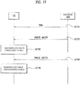
- FIG. 17 illustrates the embodiment according to the present disclosure of methods for providing MBMS.
- the E-UTRAN may include one or more eNBs.
- the UE may be in RRC_IDLE or RRC_CONNECTED state and may want to receive or be receiving MBMS. It is assumed that the E-UTRAN is capable of transmitting system information or MBMS control information to the UE through the eNB. Further, it is assumed that the UE and the eNB preserve the first table (refer to [Table 6]) and the second table, for supporting 256QAM.
- the eNB included in the E-UTRAN may transmit one or more SIBx messages to the UE in order to transmit MBMS-related system information (S1710).
- an SIB2 message includes an mbsfn-SubframeConfigList field that defines DL subframes reserved for MBSFN.
- An SIB13 message may include information for acquiring an MCCH carrying control information related to an MBSFN area, as described in [Table 8], [Table 9], and [Table 10].
- An SIB15 message may include an MBSFN service area ID for a current and/or a neighbor carrier frequency band, as illustrated in [Table 11].
- the E-UTRAN including the eNB may transmit MBMS control information to the UE by a higher-layer signal.
- the higher-layer signal carrying the MBMS control information may be an MBSFNAreaConfiguration message described with reference to the comparative example of FIG. 14 .
- the MBSFNAreaConfiguration message is transmitted on an MCCH and the MCCH may be mapped to a physical channel PMCH, for transmission.
- the UE may receive the MCCH on the PMCH based on the MCCH acquisition information including the MBSFN area-related control information, included in the SIB13 message (S1720).
- the eNB may transmit a PMCH including an MCCH without applying 256QAM to the PMCH.
- an I MCS value indicating an MCS applied to a subframe carrying the MCCH may be included in the SIB13 message. Therefore, the UE may assume that 256QAM is not applied, when it demodulates the MCCH transmitted on the PMCH and may demodulate the MCCH using an MCS and a TBS based on an I MCS index defined in the first table (see [Table 6]) (S1730).
- the eNB When the eNB transmits an MTCH on a PMCH, it may apply 256QAM. Since the MTCH is used to transmit MBMS data, the throughput of the network may be increased by applying 256QAM to the MTCH.
- the UE may acquire MTCH scheduling information (e.g., MBMS control information after demodulating the MCCH. That is, the UE may receive the MTCH based on the scheduling information (S1740).
- MTCH scheduling information e.g., MBMS control information after demodulating the MCCH. That is, the UE may receive the MTCH based on the scheduling information (S1740).
- the UE may receive and demodulate the PMCH including the MTCH based on the I MCS value included in the MBSFN area configuration information included in the MCCH demodulated in step S1730. That is, the UE may demodulate the PMCH using the MCS and TBS according to the I MCS index defined in the afore-described second table (refer to [Table 7]) (S1750).
- an MCCH and an MTCH transmitted on PMCHs may be configured on a subframe basis. That is, if support or non-support of 256QAM is determined on a subframe basis, non-support of 256QAM is indicated for a subframe carrying an MCCH, and support of 256QAM is indicated for a subframe carrying an MTCH. Therefore, the UE may receive MBMS control information robustly and the throughput of MBMS data in the system may be increased.
- MBSFN RSs are transmitted on the PMCH.
- the UE and the PMCH support 256QAM, the UE may demodulate data accurately only when it is ware of the transmission power of a transmitted signal. Since the UE may decode the PMCH in the same manner as when 16QAM/64QAM is used for the PMCH in the legacy system, the UE may demodulate the PMCH based on 256QAM without introduction of an additional scheme.
- Apparatuses illustrated in FIG. 18 are means that can implement the methods described before with reference to the comparative examples and the embodiment FIGS. 1 to 17 .
- a UE may act as a transmitting end on a UL and as a receiving end on a DL.
- An eNB may act as a receiving end on a UL and as a transmitting end on a DL.
- each of the UE and the eNB may include a Transmitter 1840 or 1850 and a Receiver 1860 or 1870, for controlling transmission and reception of information, data, and/or messages, and an antenna 1800 or 1810 for transmitting and receiving information, data, and/or messages.
- Each of the UE and the eNB may further include a processor 1820 or 1830 for implementing the afore-described embodiment of the present disclosure and a memory 1880 or 1190 for temporarily or permanently storing operations of the processor 1820 or 1830.
- the embodiment of the present invention can be performed by suing components and functions of the UE and the eNB.
- the processor of the eNB is able to maintain and manage the MCS/TBS index tables supporting the 256QAM, and the eNB is able to transmit I MCS for supporting 256QAM.
- the processor of the eNB can modulate and transmit the PMCH by applying the 256QAM.
- the processor of UE is able to receive and demodulate the PMCH modulated by the 256QAM by controlling the transmitter and the receiver.
- the specific examples are referred to the descriptions on Clause 5.
- the transmitter and the receiver of the UE and the eNB may perform a packet modulation/demodulation function for data transmission, a high-speed packet channel coding function, OFDMA packet scheduling, TDD packet scheduling, and/or channelization.
- Each of the UE and the eNB of the comparative example/embodiment of FIG. 18 may further include a low-power Radio Frequency (RF)/Intermediate Frequency (IF) module.
- RF Radio Frequency
- IF Intermediate Frequency
- the UE may be any of a Personal Digital Assistant (PDA), a cellular phone, a Personal Communication Service (PCS) phone, a Global System for Mobile (GSM) phone, a Wideband Code Division Multiple Access (WCDMA) phone, a Mobile Broadband System (MBS) phone, a hand-held PC, a laptop PC, a smart phone, a Multi-Mode-Multi Band (MM-MB) terminal, etc.
- PDA Personal Digital Assistant
- PCS Personal Communication Service
- GSM Global System for Mobile
- WCDMA Wideband Code Division Multiple Access
- MBS Mobile Broadband System
- hand-held PC a laptop PC
- smart phone a Multi-Mode-Multi Band (MM-MB) terminal, etc.
- MM-MB Multi-Mode-Multi Band
- the smart phone is a terminal taking the advantages of both a mobile phone and a PDA. It incorporates the functions of a PDA, that is, scheduling and data communications such as fax transmission and reception and Internet connection into a mobile phone.
- the MB-MM terminal refers to a terminal which has a multi-modem chip built therein and which can operate in any of a mobile Internet system and other mobile communication systems (e.g. CDMA 2000, WCDMA, etc.).
- the embodiment of the present disclosure may be achieved by various means, for example, hardware, firmware, software, or a combination thereof.
- the methods according to the embodiment of the present disclosure may be achieved by one or more Application Specific Integrated Circuits (ASICs), Digital Signal Processors (DSPs), Digital Signal Processing Devices (DSPDs), Programmable Logic Devices (PLDs), Field Programmable Gate Arrays (FPGAs), processors, controllers, microcontrollers, microprocessors, etc.
- ASICs Application Specific Integrated Circuits
- DSPs Digital Signal Processors
- DSPDs Digital Signal Processing Devices
- PLDs Programmable Logic Devices
- FPGAs Field Programmable Gate Arrays
- processors controllers, microcontrollers, microprocessors, etc.
- the methods according to the embodiment of the present disclosure may be implemented in the form of a module, a procedure, a function, etc. performing the above-described functions or operations.
- a software code may be stored in the memory 1880 or 1890 and executed by the processor 1820 or 1830.
- the memory is located at the interior or exterior of the processor and may transmit and receive data to and from the processor via various known means.
- the embodiment of the present invention is applicable to various wireless access systems including a 3GPP system, a 3GPP2 system, and/or an IEEE 802.xx system. In addition to these wireless access systems, the embodiment of the present invention is applicable to all technical fields in which the wireless access systems find their applications.
Landscapes
- Engineering & Computer Science (AREA)
- Signal Processing (AREA)
- Computer Networks & Wireless Communication (AREA)
- Quality & Reliability (AREA)
- Mobile Radio Communication Systems (AREA)
Claims (15)
- Procédé de réception d'un canal physique de multidiffusion, PMCH, par un équipement utilisateur, UE, dans un système d'accès sans fil prenant en charge une modulation d'amplitude en quadrature, 256QAM, le procédé consistant à :recevoir (S1710) un bloc d'informations de système, SIB, comprenant des informations destinées à acquérir un canal de contrôle de multidiffusion, MCCH ;recevoir (S1720) un PMCH portant un MCCH comprenant des informations de contrôle de services de diffusion MBMS ; etrecevoir (S1740) un PMCH portant un canal de trafic de multidiffusion, MTCH, comprenant des données de MBMS en fonction des informations de contrôle de MBMS,la 256QAM n'étant pas appliquée au PMCH portant le MCCH, etl'UE extrayant (S1750) un schéma de modulation et de codage, MCS, et une taille de bloc de transport, TBS, à l'aide d'une table prenant en charge 256QAM pour recevoir et démoduler le PMCH portant le MTCH.
- Procédé selon la revendication 1, l'UE recevant le PMCH portant le MTCH selon la supposition qu'une énergie de PMCH par élément de ressource, EPRE, est égale à un signal de référence, RS, EPRE, de réseau d'isofréquence MBSFN.
- Procédé selon la revendication 1 ou 2, le PMCH portant le MCCH étant démodulé en fonction d'une table conçue pour prendre en charge le schéma de modulation patrimonial jusqu'à 64 QAM.
- Procédé de transmission d'un canal physique de multidiffusion, PMCH, par un noeud évolué B, eNB, dans un système d'accès sans fil prenant en charge une modulation d'amplitude en quadrature 256-ary, le procédé consistant à :transmettre (S1710) un bloc d'informations de système, SIB, comprenant des informations destinées à acquérir un canal de contrôle de multidiffusion, MCCH ;transmettre (S1720) un PMCH portant un MCCH comprenant des informations de contrôle de service de diffusion MBMS ; ettransmettre (S1740) un PMCH portant un canal de trafic de multidiffusion, MTCH, comprenant des données MBMS en fonction des informations de contrôle de MBMS,la 256QAM n'étant pas appliquée au PMCH portant le MCCH, etl'eNB modulant le PMCH portant le MTCH en fonction d'une table prenant en charge la 256QAM.
- Procédé selon la revendication 4, le PMCH portant le MCCH étant modulé en fonction d'une table configurée pour prendre en charge un schéma de modulation patrimonial jusqu'à 64 QAM.
- Procédé selon l'une quelconque des revendications 1 à 5, il est configuré sur une base de sous-trame si la 256QAM est prise en charge ou non.
- Procédé selon l'une quelconque des revendications 1 à 6, les informations de contrôle de MBMS étant comprises dans un message de configuration de zone de MBSFN et le message de configuration de zone de MBSFN étant transmis sur le MCCH.
- Procédé selon l'une quelconque des revendications 1 à 7, le SIB indiquant si 256QAM est pris en charge ou non sur une base de zone de MBSFN.
- Support lisible par ordinateur (1880, 1890) comprenant des parties de code qui, lorsqu'elles sont exécutées dans un processeur (1820, 1830), configurent le processeur pour effectuer toutes les étapes d'un procédé selon l'une quelconque des revendications précédentes.
- Equipement d'utilisateur, UE, destiné à recevoir un canal physique de multidiffusion, PMCH, dans un système d'accès sans fil prenant en charge une modulation d'amplitude en quadrature 256-ary, l'UE comprenant :un récepteur (1850) ; etun processeur (1830) connecté fonctionnellement à l'émetteur-récepteur et configuré pour recevoir le PMCH prenant en charge 256QAM,le processeur étant configuré pour :- recevoir un bloc d'informations de système, SIB, comprenant des informations destinées à acquérir un canal de contrôle de multidiffusion, MCCH, en commandant le récepteur ;- recevoir un PMCH portant un MCCH comprenant des informations de service de diffusion MBMS, en commandant le récepteur ; et- recevoir un PMCH portant un canal de trafic de multidiffusion, MTCH, comprenant des données de MBMS en fonction des informations de contrôle de MBMS en commandant le récepteur,256QAM n'étant pas appliquée au PMCH portant le MCCH, etle processeur étant configuré pour extraire un schéma de modulation et de codage, MCS, et une taille de bloc de transport, TBS, à l'aide d'une table prenant en charge la 256QAM pour recevoir et démoduler le PMCH portant le MTCH.
- UE selon la revendication 10 :- il est configuré sur une base de sous-trame si 256QAM est pris en charge ou non ;- les informations de contrôle de MBMS étant comprises dans un message de configuration de zone de MBSFN et le message de configuration de zone de MBSFN étant transmis sur le MCCH ; et- le SIB indiquant si 256QAM est prise en charge ou non sur une base de zone de MBSFN.
- UE selon la revendication 10 ou 11, le processeur étant configuré pour :- recevoir le PMCH portant le MTCH selon la supposition qu'une énergie de PMCH par élément de ressource, EPRE, est égale à un signal de référence, RS, EPRE, de réseau d'isofréquence MBSFN ; et- démoduler le PMCH portant le MCCH en fonction d'une table configurée pour prendre en charge le schéma de modulation patrimonial jusqu'à 64QAM.
- Noeud B évolué, eNB, destiné à recevoir un canal physique de multidiffusion, PMCH, dans un système d'accès sans fil prenant en charge une modulation d'amplitude en quadrature 256-ary, 256QAM, l'eNB comprenant :Un émetteur (1850) ; etUn processeur (1830) connecté fonctionnellement à l'émetteur et configuré pour transmettre le PMCH prenant en charge la 256QAM,- transmettre un bloc d'informations de système, SIB, comprenant des informations destinées à acquérir un canal de contrôle de diffusion, MCCH, en commandant le récepteur ;- transmettre un PMCH portant un canal de trafic de multidiffusion, MTCH, comprenant des données de MBMS en fonction des informations de contrôle de MBMS en commandant le récepteur,256QAM n'étant pas appliquée au PMCH portant le MCCH, etLe processeur étant configuré pour moduler le PMCH portant le MTCH en fonction d'une table prenant en charge la 256QAM.
- eNB selon la revendication 13 :- s'il est configuré que la 256 QAM étant prise en charge ou non sur la base de sous-trame ;- les informations de contrôle de MBMS étant comprises dans un message de configuration de zone de MBSFN et le message de configuration de zone de MBSFN étant transmis sur le MCCH ;Et- si le SIB indique si la 256QAM est prise en charge ou non sur une base de zone de MBSFN.
- eNB selon la revendication 13 ou 14, le processeur étant configuré pour :- moduler le PMCH portant le MCCH en fonction d'une table configurée pour prendre en charge un schéma de modulation patrimonial jusqu'à 64QAM.
Applications Claiming Priority (2)
| Application Number | Priority Date | Filing Date | Title |
|---|---|---|---|
| US201462021206P | 2014-07-06 | 2014-07-06 | |
| PCT/KR2015/006713 WO2016006860A1 (fr) | 2014-07-06 | 2015-06-30 | Procédé et dispositif de réception de canal physique de multidiffusion dans un système d'accès sans fil supportant un schéma 256qam |
Publications (3)
| Publication Number | Publication Date |
|---|---|
| EP3166272A1 EP3166272A1 (fr) | 2017-05-10 |
| EP3166272A4 EP3166272A4 (fr) | 2018-02-21 |
| EP3166272B1 true EP3166272B1 (fr) | 2019-04-24 |
Family
ID=55064431
Family Applications (1)
| Application Number | Title | Priority Date | Filing Date |
|---|---|---|---|
| EP15819197.3A Active EP3166272B1 (fr) | 2014-07-06 | 2015-06-30 | Procédé et dispositif de réception de canal physique de multidiffusion dans un système d'accès sans fil supportant un schéma 256qam |
Country Status (5)
| Country | Link |
|---|---|
| US (1) | US10200207B2 (fr) |
| EP (1) | EP3166272B1 (fr) |
| JP (1) | JP6426822B2 (fr) |
| TW (1) | TWI549542B (fr) |
| WO (1) | WO2016006860A1 (fr) |
Families Citing this family (12)
| Publication number | Priority date | Publication date | Assignee | Title |
|---|---|---|---|---|
| US9722848B2 (en) | 2014-05-08 | 2017-08-01 | Intel Corporation | Techniques for using a modulation and coding scheme for downlink transmissions |
| KR102458067B1 (ko) | 2016-03-30 | 2022-10-24 | 삼성전자 주식회사 | 이동 통신 시스템에서의 신호 전송 방법 및 장치 |
| US9894458B2 (en) * | 2016-04-25 | 2018-02-13 | Verizon Patent And Licensing Inc. | Optimizing MTC updates using MBMS |
| WO2018021812A1 (fr) * | 2016-07-26 | 2018-02-01 | 엘지전자 주식회사 | Procédé et dispositif pour recevoir des informations de commande de services mbms par le biais d'un faisceau |
| CN107734646A (zh) * | 2016-08-11 | 2018-02-23 | 电信科学技术研究院 | 一种多播业务信息的发送方法、接收方法、基站及终端 |
| MX2019009146A (es) | 2017-02-03 | 2019-09-10 | Ericsson Telefon Ab L M | Metodos, equipo de usuario y nodo de red de radio para el servicio de multifusion por difusión multimedia. |
| US11190975B2 (en) | 2017-02-13 | 2021-11-30 | Qualcomm Incorporated | Feedback techniques for wireless communications |
| IT201800000832A1 (it) * | 2018-01-12 | 2019-07-12 | Inst Rundfunktechnik Gmbh | Sender und/oder empfänger zum senden bzw. empfangen von rundfunkinformationssignalen |
| US10708866B2 (en) * | 2018-04-05 | 2020-07-07 | Samsung Electronics Co., Ltd. | Signaling of control information in a communication system |
| CN112087720B (zh) * | 2019-06-12 | 2023-10-24 | 华为技术有限公司 | 一种通信方法和装置 |
| US12219580B2 (en) | 2019-12-20 | 2025-02-04 | Interdigital Patent Holdings, Inc. | Methods, apparatus, and systems for resource allocation for multimedia broadcast multicast service (MBMS) in wireless systems |
| US11785611B2 (en) * | 2020-07-09 | 2023-10-10 | Mediatek Inc. | Method for performing 2-stage downlink control information based cross-carrier scheduling in carrier aggregation |
Family Cites Families (12)
| Publication number | Priority date | Publication date | Assignee | Title |
|---|---|---|---|---|
| US8503546B1 (en) | 2008-01-31 | 2013-08-06 | Quantum XTEL, Inc. | Multiple layer overlay modulation |
| US8351467B2 (en) | 2009-02-06 | 2013-01-08 | Qualcomm Incorporated | Methods and systems for providing MBMS data to subscriber stations |
| CN101924998B (zh) * | 2009-06-09 | 2011-12-21 | 电信科学技术研究院 | 一种数据传输方法、系统及装置 |
| US8457033B2 (en) * | 2009-06-19 | 2013-06-04 | Innovative Sonic Corporation | Method and apparatus for handling MBMS dynamic scheduling information |
| CN102742181B (zh) * | 2010-06-13 | 2014-12-10 | Lg电子株式会社 | 在无线通信系统中对终端发送指示服务区域的计数响应消息的方法及其设备 |
| KR101948801B1 (ko) * | 2011-04-11 | 2019-02-18 | 삼성전자주식회사 | Mbms 지원 사용자 장치의 데이터 수신 방법 및 장치 |
| JP2014515226A (ja) | 2011-04-14 | 2014-06-26 | アルカテル−ルーセント | 低次変調器を使用して高次変調方式を実施する方法および装置 |
| KR101935785B1 (ko) | 2011-08-16 | 2019-04-03 | 삼성전자 주식회사 | 무선통신시스템에서 멀티미디어 방송 서비스를 수신하는 방법 및 장치 |
| WO2015054201A2 (fr) * | 2013-10-07 | 2015-04-16 | Nokia Solutions And Networks Oy | Définition de ressources d'estimation d'interférence et son utilisation pour des récepteurs améliorés |
| US9722848B2 (en) * | 2014-05-08 | 2017-08-01 | Intel Corporation | Techniques for using a modulation and coding scheme for downlink transmissions |
| KR102241827B1 (ko) * | 2014-05-16 | 2021-04-19 | 삼성전자 주식회사 | 복수의 캐리어들을 지원하는 이동 통신 시스템에서 신호 송/수신 방법 및 장치 |
| US10554708B2 (en) * | 2015-03-27 | 2020-02-04 | Qualcomm Incorporated | Point-to-multipoint broadcast assisted vehicle-to-X broadcast |
-
2015
- 2015-06-30 EP EP15819197.3A patent/EP3166272B1/fr active Active
- 2015-06-30 US US15/324,465 patent/US10200207B2/en active Active
- 2015-06-30 JP JP2017500996A patent/JP6426822B2/ja active Active
- 2015-06-30 WO PCT/KR2015/006713 patent/WO2016006860A1/fr not_active Ceased
- 2015-07-02 TW TW104121501A patent/TWI549542B/zh active
Non-Patent Citations (1)
| Title |
|---|
| None * |
Also Published As
| Publication number | Publication date |
|---|---|
| US10200207B2 (en) | 2019-02-05 |
| JP2017529719A (ja) | 2017-10-05 |
| US20170207925A1 (en) | 2017-07-20 |
| TWI549542B (zh) | 2016-09-11 |
| EP3166272A4 (fr) | 2018-02-21 |
| TW201607346A (zh) | 2016-02-16 |
| WO2016006860A1 (fr) | 2016-01-14 |
| EP3166272A1 (fr) | 2017-05-10 |
| JP6426822B2 (ja) | 2018-11-21 |
Similar Documents
| Publication | Publication Date | Title |
|---|---|---|
| EP3166272B1 (fr) | Procédé et dispositif de réception de canal physique de multidiffusion dans un système d'accès sans fil supportant un schéma 256qam | |
| US11082955B2 (en) | Method and device for transmitting/receiving data using transport block size defined for machine type communication terminal in wireless access system supporting machine type communication | |
| US10231261B2 (en) | Method and apparatus for transmitting and receiving MCS index for 256QAM in wireless access system | |
| US10285139B2 (en) | Power control method and apparatus in wireless access system | |
| EP3349379B1 (fr) | Procédé et appareil pour recevoir un canal physique de diffusion de liaison descendante dans un système d'accès radio qui prend en charge un internet des objets à bande étroite | |
| US10117217B2 (en) | Method and apparatus for transmitting positioning reference signal in wireless access system supporting machine type communication | |
| EP3062542B1 (fr) | Procédé pour transmettre un canal de diffusion dans un système d'accès sans fil prenant en charge une communication de type machine, et appareil le prenant en charge | |
| EP2978230B1 (fr) | Procédé pour l'allocation d'un canal de diffusion, procédé pour la transmission et la réception d'un signal d'un canal de diffusion, et dispositif pour la mise en uvre de ces procédés | |
| EP3079414A1 (fr) | Procédé et appareil pour commander la puissance d'émission d'une liaison montante dans un système d'accès sans fil acceptant une communication de type machine | |
| EP2983306A1 (fr) | Procédé de transmission d'informations de commande en liaison montante dans un système d'accès sans fil et appareil associé | |
| US10230562B2 (en) | Method and device for supporting 256QAM in wireless access system | |
| US20170164407A1 (en) | Method for transmitting and receiving control information for broadcast multicast service, and device therefor | |
| US10244508B2 (en) | Method and device by which machine type communication terminal transmits and receives data in wireless access system supporting machine type communication | |
| US9531576B2 (en) | Method and apparatus for transmitting modulation symbol using 256QAM in a wireless access system | |
| EP3062452B1 (fr) | Procédé et appareil de transmission de canal de commande physique de liaison descendante dans un système d'accès sans fil prenant en charge une communication de type machine |
Legal Events
| Date | Code | Title | Description |
|---|---|---|---|
| STAA | Information on the status of an ep patent application or granted ep patent |
Free format text: STATUS: THE INTERNATIONAL PUBLICATION HAS BEEN MADE |
|
| PUAI | Public reference made under article 153(3) epc to a published international application that has entered the european phase |
Free format text: ORIGINAL CODE: 0009012 |
|
| STAA | Information on the status of an ep patent application or granted ep patent |
Free format text: STATUS: REQUEST FOR EXAMINATION WAS MADE |
|
| 17P | Request for examination filed |
Effective date: 20170111 |
|
| AK | Designated contracting states |
Kind code of ref document: A1 Designated state(s): AL AT BE BG CH CY CZ DE DK EE ES FI FR GB GR HR HU IE IS IT LI LT LU LV MC MK MT NL NO PL PT RO RS SE SI SK SM TR |
|
| AX | Request for extension of the european patent |
Extension state: BA ME |
|
| DAV | Request for validation of the european patent (deleted) | ||
| DAX | Request for extension of the european patent (deleted) | ||
| A4 | Supplementary search report drawn up and despatched |
Effective date: 20180118 |
|
| RIC1 | Information provided on ipc code assigned before grant |
Ipc: H04L 27/34 20060101ALI20180112BHEP Ipc: H04L 5/00 20060101AFI20180112BHEP |
|
| REG | Reference to a national code |
Ref country code: DE Ref legal event code: R079 Ref document number: 602015029034 Country of ref document: DE Free format text: PREVIOUS MAIN CLASS: H04L0027340000 Ipc: H04L0005000000 |
|
| GRAP | Despatch of communication of intention to grant a patent |
Free format text: ORIGINAL CODE: EPIDOSNIGR1 |
|
| STAA | Information on the status of an ep patent application or granted ep patent |
Free format text: STATUS: GRANT OF PATENT IS INTENDED |
|
| RIC1 | Information provided on ipc code assigned before grant |
Ipc: H04L 1/18 20060101ALN20181024BHEP Ipc: H04L 27/34 20060101ALI20181024BHEP Ipc: H04L 5/00 20060101AFI20181024BHEP |
|
| INTG | Intention to grant announced |
Effective date: 20181128 |
|
| GRAS | Grant fee paid |
Free format text: ORIGINAL CODE: EPIDOSNIGR3 |
|
| GRAA | (expected) grant |
Free format text: ORIGINAL CODE: 0009210 |
|
| STAA | Information on the status of an ep patent application or granted ep patent |
Free format text: STATUS: THE PATENT HAS BEEN GRANTED |
|
| AK | Designated contracting states |
Kind code of ref document: B1 Designated state(s): AL AT BE BG CH CY CZ DE DK EE ES FI FR GB GR HR HU IE IS IT LI LT LU LV MC MK MT NL NO PL PT RO RS SE SI SK SM TR |
|
| REG | Reference to a national code |
Ref country code: GB Ref legal event code: FG4D |
|
| REG | Reference to a national code |
Ref country code: CH Ref legal event code: EP |
|
| REG | Reference to a national code |
Ref country code: AT Ref legal event code: REF Ref document number: 1125404 Country of ref document: AT Kind code of ref document: T Effective date: 20190515 Ref country code: IE Ref legal event code: FG4D |
|
| REG | Reference to a national code |
Ref country code: DE Ref legal event code: R096 Ref document number: 602015029034 Country of ref document: DE |
|
| REG | Reference to a national code |
Ref country code: NL Ref legal event code: FP |
|
| REG | Reference to a national code |
Ref country code: LT Ref legal event code: MG4D |
|
| PG25 | Lapsed in a contracting state [announced via postgrant information from national office to epo] |
Ref country code: ES Free format text: LAPSE BECAUSE OF FAILURE TO SUBMIT A TRANSLATION OF THE DESCRIPTION OR TO PAY THE FEE WITHIN THE PRESCRIBED TIME-LIMIT Effective date: 20190424 Ref country code: HR Free format text: LAPSE BECAUSE OF FAILURE TO SUBMIT A TRANSLATION OF THE DESCRIPTION OR TO PAY THE FEE WITHIN THE PRESCRIBED TIME-LIMIT Effective date: 20190424 Ref country code: AL Free format text: LAPSE BECAUSE OF FAILURE TO SUBMIT A TRANSLATION OF THE DESCRIPTION OR TO PAY THE FEE WITHIN THE PRESCRIBED TIME-LIMIT Effective date: 20190424 Ref country code: PT Free format text: LAPSE BECAUSE OF FAILURE TO SUBMIT A TRANSLATION OF THE DESCRIPTION OR TO PAY THE FEE WITHIN THE PRESCRIBED TIME-LIMIT Effective date: 20190824 Ref country code: NO Free format text: LAPSE BECAUSE OF FAILURE TO SUBMIT A TRANSLATION OF THE DESCRIPTION OR TO PAY THE FEE WITHIN THE PRESCRIBED TIME-LIMIT Effective date: 20190724 Ref country code: SE Free format text: LAPSE BECAUSE OF FAILURE TO SUBMIT A TRANSLATION OF THE DESCRIPTION OR TO PAY THE FEE WITHIN THE PRESCRIBED TIME-LIMIT Effective date: 20190424 Ref country code: FI Free format text: LAPSE BECAUSE OF FAILURE TO SUBMIT A TRANSLATION OF THE DESCRIPTION OR TO PAY THE FEE WITHIN THE PRESCRIBED TIME-LIMIT Effective date: 20190424 Ref country code: LT Free format text: LAPSE BECAUSE OF FAILURE TO SUBMIT A TRANSLATION OF THE DESCRIPTION OR TO PAY THE FEE WITHIN THE PRESCRIBED TIME-LIMIT Effective date: 20190424 |
|
| PG25 | Lapsed in a contracting state [announced via postgrant information from national office to epo] |
Ref country code: RS Free format text: LAPSE BECAUSE OF FAILURE TO SUBMIT A TRANSLATION OF THE DESCRIPTION OR TO PAY THE FEE WITHIN THE PRESCRIBED TIME-LIMIT Effective date: 20190424 Ref country code: BG Free format text: LAPSE BECAUSE OF FAILURE TO SUBMIT A TRANSLATION OF THE DESCRIPTION OR TO PAY THE FEE WITHIN THE PRESCRIBED TIME-LIMIT Effective date: 20190724 Ref country code: LV Free format text: LAPSE BECAUSE OF FAILURE TO SUBMIT A TRANSLATION OF THE DESCRIPTION OR TO PAY THE FEE WITHIN THE PRESCRIBED TIME-LIMIT Effective date: 20190424 Ref country code: GR Free format text: LAPSE BECAUSE OF FAILURE TO SUBMIT A TRANSLATION OF THE DESCRIPTION OR TO PAY THE FEE WITHIN THE PRESCRIBED TIME-LIMIT Effective date: 20190725 Ref country code: PL Free format text: LAPSE BECAUSE OF FAILURE TO SUBMIT A TRANSLATION OF THE DESCRIPTION OR TO PAY THE FEE WITHIN THE PRESCRIBED TIME-LIMIT Effective date: 20190424 |
|
| REG | Reference to a national code |
Ref country code: AT Ref legal event code: MK05 Ref document number: 1125404 Country of ref document: AT Kind code of ref document: T Effective date: 20190424 |
|
| PG25 | Lapsed in a contracting state [announced via postgrant information from national office to epo] |
Ref country code: IS Free format text: LAPSE BECAUSE OF FAILURE TO SUBMIT A TRANSLATION OF THE DESCRIPTION OR TO PAY THE FEE WITHIN THE PRESCRIBED TIME-LIMIT Effective date: 20190824 |
|
| REG | Reference to a national code |
Ref country code: DE Ref legal event code: R097 Ref document number: 602015029034 Country of ref document: DE |
|
| PG25 | Lapsed in a contracting state [announced via postgrant information from national office to epo] |
Ref country code: AT Free format text: LAPSE BECAUSE OF FAILURE TO SUBMIT A TRANSLATION OF THE DESCRIPTION OR TO PAY THE FEE WITHIN THE PRESCRIBED TIME-LIMIT Effective date: 20190424 Ref country code: MC Free format text: LAPSE BECAUSE OF FAILURE TO SUBMIT A TRANSLATION OF THE DESCRIPTION OR TO PAY THE FEE WITHIN THE PRESCRIBED TIME-LIMIT Effective date: 20190424 Ref country code: EE Free format text: LAPSE BECAUSE OF FAILURE TO SUBMIT A TRANSLATION OF THE DESCRIPTION OR TO PAY THE FEE WITHIN THE PRESCRIBED TIME-LIMIT Effective date: 20190424 Ref country code: DK Free format text: LAPSE BECAUSE OF FAILURE TO SUBMIT A TRANSLATION OF THE DESCRIPTION OR TO PAY THE FEE WITHIN THE PRESCRIBED TIME-LIMIT Effective date: 20190424 Ref country code: RO Free format text: LAPSE BECAUSE OF FAILURE TO SUBMIT A TRANSLATION OF THE DESCRIPTION OR TO PAY THE FEE WITHIN THE PRESCRIBED TIME-LIMIT Effective date: 20190424 Ref country code: CZ Free format text: LAPSE BECAUSE OF FAILURE TO SUBMIT A TRANSLATION OF THE DESCRIPTION OR TO PAY THE FEE WITHIN THE PRESCRIBED TIME-LIMIT Effective date: 20190424 Ref country code: SK Free format text: LAPSE BECAUSE OF FAILURE TO SUBMIT A TRANSLATION OF THE DESCRIPTION OR TO PAY THE FEE WITHIN THE PRESCRIBED TIME-LIMIT Effective date: 20190424 |
|
| REG | Reference to a national code |
Ref country code: CH Ref legal event code: PL |
|
| PG25 | Lapsed in a contracting state [announced via postgrant information from national office to epo] |
Ref country code: IT Free format text: LAPSE BECAUSE OF FAILURE TO SUBMIT A TRANSLATION OF THE DESCRIPTION OR TO PAY THE FEE WITHIN THE PRESCRIBED TIME-LIMIT Effective date: 20190424 Ref country code: SM Free format text: LAPSE BECAUSE OF FAILURE TO SUBMIT A TRANSLATION OF THE DESCRIPTION OR TO PAY THE FEE WITHIN THE PRESCRIBED TIME-LIMIT Effective date: 20190424 |
|
| PLBE | No opposition filed within time limit |
Free format text: ORIGINAL CODE: 0009261 |
|
| STAA | Information on the status of an ep patent application or granted ep patent |
Free format text: STATUS: NO OPPOSITION FILED WITHIN TIME LIMIT |
|
| GBPC | Gb: european patent ceased through non-payment of renewal fee |
Effective date: 20190724 |
|
| REG | Reference to a national code |
Ref country code: BE Ref legal event code: MM Effective date: 20190630 |
|
| PG25 | Lapsed in a contracting state [announced via postgrant information from national office to epo] |
Ref country code: TR Free format text: LAPSE BECAUSE OF FAILURE TO SUBMIT A TRANSLATION OF THE DESCRIPTION OR TO PAY THE FEE WITHIN THE PRESCRIBED TIME-LIMIT Effective date: 20190424 |
|
| 26N | No opposition filed |
Effective date: 20200127 |
|
| PG25 | Lapsed in a contracting state [announced via postgrant information from national office to epo] |
Ref country code: IE Free format text: LAPSE BECAUSE OF NON-PAYMENT OF DUE FEES Effective date: 20190630 Ref country code: GB Free format text: LAPSE BECAUSE OF NON-PAYMENT OF DUE FEES Effective date: 20190724 |
|
| PG25 | Lapsed in a contracting state [announced via postgrant information from national office to epo] |
Ref country code: LI Free format text: LAPSE BECAUSE OF NON-PAYMENT OF DUE FEES Effective date: 20190630 Ref country code: CH Free format text: LAPSE BECAUSE OF NON-PAYMENT OF DUE FEES Effective date: 20190630 Ref country code: SI Free format text: LAPSE BECAUSE OF FAILURE TO SUBMIT A TRANSLATION OF THE DESCRIPTION OR TO PAY THE FEE WITHIN THE PRESCRIBED TIME-LIMIT Effective date: 20190424 Ref country code: LU Free format text: LAPSE BECAUSE OF NON-PAYMENT OF DUE FEES Effective date: 20190630 Ref country code: BE Free format text: LAPSE BECAUSE OF NON-PAYMENT OF DUE FEES Effective date: 20190630 |
|
| PG25 | Lapsed in a contracting state [announced via postgrant information from national office to epo] |
Ref country code: CY Free format text: LAPSE BECAUSE OF FAILURE TO SUBMIT A TRANSLATION OF THE DESCRIPTION OR TO PAY THE FEE WITHIN THE PRESCRIBED TIME-LIMIT Effective date: 20190424 |
|
| PG25 | Lapsed in a contracting state [announced via postgrant information from national office to epo] |
Ref country code: MT Free format text: LAPSE BECAUSE OF FAILURE TO SUBMIT A TRANSLATION OF THE DESCRIPTION OR TO PAY THE FEE WITHIN THE PRESCRIBED TIME-LIMIT Effective date: 20190424 Ref country code: HU Free format text: LAPSE BECAUSE OF FAILURE TO SUBMIT A TRANSLATION OF THE DESCRIPTION OR TO PAY THE FEE WITHIN THE PRESCRIBED TIME-LIMIT; INVALID AB INITIO Effective date: 20150630 |
|
| PG25 | Lapsed in a contracting state [announced via postgrant information from national office to epo] |
Ref country code: MK Free format text: LAPSE BECAUSE OF FAILURE TO SUBMIT A TRANSLATION OF THE DESCRIPTION OR TO PAY THE FEE WITHIN THE PRESCRIBED TIME-LIMIT Effective date: 20190424 |
|
| P01 | Opt-out of the competence of the unified patent court (upc) registered |
Effective date: 20230524 |
|
| PGFP | Annual fee paid to national office [announced via postgrant information from national office to epo] |
Ref country code: NL Payment date: 20250508 Year of fee payment: 11 |
|
| PGFP | Annual fee paid to national office [announced via postgrant information from national office to epo] |
Ref country code: DE Payment date: 20250508 Year of fee payment: 11 |
|
| PGFP | Annual fee paid to national office [announced via postgrant information from national office to epo] |
Ref country code: FR Payment date: 20250513 Year of fee payment: 11 |