EP3166331A1 - Systems and methods for compressing a digital signal in a digital microphone system - Google Patents
Systems and methods for compressing a digital signal in a digital microphone system Download PDFInfo
- Publication number
- EP3166331A1 EP3166331A1 EP16183887.5A EP16183887A EP3166331A1 EP 3166331 A1 EP3166331 A1 EP 3166331A1 EP 16183887 A EP16183887 A EP 16183887A EP 3166331 A1 EP3166331 A1 EP 3166331A1
- Authority
- EP
- European Patent Office
- Prior art keywords
- digital
- signal
- digital signal
- quantization level
- analog input
- Prior art date
- Legal status (The legal status is an assumption and is not a legal conclusion. Google has not performed a legal analysis and makes no representation as to the accuracy of the status listed.)
- Withdrawn
Links
Images

Classifications
-
- H—ELECTRICITY
- H04—ELECTRIC COMMUNICATION TECHNIQUE
- H04R—LOUDSPEAKERS, MICROPHONES, GRAMOPHONE PICK-UPS OR LIKE ACOUSTIC ELECTROMECHANICAL TRANSDUCERS; ELECTRIC HEARING AIDS; PUBLIC ADDRESS SYSTEMS
- H04R3/00—Circuits for transducers
- H04R3/02—Circuits for transducers for preventing acoustic reaction, i.e. acoustic oscillatory feedback
-
- H—ELECTRICITY
- H03—ELECTRONIC CIRCUITRY
- H03F—AMPLIFIERS
- H03F1/00—Details of amplifiers with only discharge tubes, only semiconductor devices or only unspecified devices as amplifying elements
- H03F1/26—Modifications of amplifiers to reduce influence of noise generated by amplifying elements
-
- H—ELECTRICITY
- H03—ELECTRONIC CIRCUITRY
- H03F—AMPLIFIERS
- H03F3/00—Amplifiers with only discharge tubes or only semiconductor devices as amplifying elements
- H03F3/04—Amplifiers with only discharge tubes or only semiconductor devices as amplifying elements with semiconductor devices only
- H03F3/16—Amplifiers with only discharge tubes or only semiconductor devices as amplifying elements with semiconductor devices only with field-effect devices
-
- H—ELECTRICITY
- H03—ELECTRONIC CIRCUITRY
- H03M—CODING; DECODING; CODE CONVERSION IN GENERAL
- H03M3/00—Conversion of analogue values to or from differential modulation
-
- H—ELECTRICITY
- H03—ELECTRONIC CIRCUITRY
- H03M—CODING; DECODING; CODE CONVERSION IN GENERAL
- H03M3/00—Conversion of analogue values to or from differential modulation
- H03M3/30—Delta-sigma modulation
- H03M3/39—Structural details of delta-sigma modulators, e.g. incremental delta-sigma modulators
- H03M3/412—Structural details of delta-sigma modulators, e.g. incremental delta-sigma modulators characterised by the number of quantisers and their type and resolution
- H03M3/422—Structural details of delta-sigma modulators, e.g. incremental delta-sigma modulators characterised by the number of quantisers and their type and resolution having one quantiser only
- H03M3/424—Structural details of delta-sigma modulators, e.g. incremental delta-sigma modulators characterised by the number of quantisers and their type and resolution having one quantiser only the quantiser being a multiple bit one
-
- H—ELECTRICITY
- H03—ELECTRONIC CIRCUITRY
- H03M—CODING; DECODING; CODE CONVERSION IN GENERAL
- H03M7/00—Conversion of a code where information is represented by a given sequence or number of digits to a code where the same, similar or subset of information is represented by a different sequence or number of digits
- H03M7/30—Compression; Expansion; Suppression of unnecessary data, e.g. redundancy reduction
- H03M7/3002—Conversion to or from differential modulation
- H03M7/3004—Digital delta-sigma modulation
- H03M7/3015—Structural details of digital delta-sigma modulators
- H03M7/302—Structural details of digital delta-sigma modulators characterised by the number of quantisers and their type and resolution
- H03M7/3024—Structural details of digital delta-sigma modulators characterised by the number of quantisers and their type and resolution having one quantiser only
- H03M7/3026—Structural details of digital delta-sigma modulators characterised by the number of quantisers and their type and resolution having one quantiser only the quantiser being a multiple bit one
-
- H—ELECTRICITY
- H03—ELECTRONIC CIRCUITRY
- H03M—CODING; DECODING; CODE CONVERSION IN GENERAL
- H03M7/00—Conversion of a code where information is represented by a given sequence or number of digits to a code where the same, similar or subset of information is represented by a different sequence or number of digits
- H03M7/30—Compression; Expansion; Suppression of unnecessary data, e.g. redundancy reduction
- H03M7/3002—Conversion to or from differential modulation
- H03M7/3004—Digital delta-sigma modulation
- H03M7/3015—Structural details of digital delta-sigma modulators
- H03M7/302—Structural details of digital delta-sigma modulators characterised by the number of quantisers and their type and resolution
- H03M7/3024—Structural details of digital delta-sigma modulators characterised by the number of quantisers and their type and resolution having one quantiser only
- H03M7/3028—Structural details of digital delta-sigma modulators characterised by the number of quantisers and their type and resolution having one quantiser only the quantiser being a single bit one
-
- H—ELECTRICITY
- H04—ELECTRIC COMMUNICATION TECHNIQUE
- H04R—LOUDSPEAKERS, MICROPHONES, GRAMOPHONE PICK-UPS OR LIKE ACOUSTIC ELECTROMECHANICAL TRANSDUCERS; ELECTRIC HEARING AIDS; PUBLIC ADDRESS SYSTEMS
- H04R29/00—Monitoring arrangements; Testing arrangements
- H04R29/001—Monitoring arrangements; Testing arrangements for loudspeakers
-
- H—ELECTRICITY
- H04—ELECTRIC COMMUNICATION TECHNIQUE
- H04R—LOUDSPEAKERS, MICROPHONES, GRAMOPHONE PICK-UPS OR LIKE ACOUSTIC ELECTROMECHANICAL TRANSDUCERS; ELECTRIC HEARING AIDS; PUBLIC ADDRESS SYSTEMS
- H04R3/00—Circuits for transducers
-
- H—ELECTRICITY
- H04—ELECTRIC COMMUNICATION TECHNIQUE
- H04R—LOUDSPEAKERS, MICROPHONES, GRAMOPHONE PICK-UPS OR LIKE ACOUSTIC ELECTROMECHANICAL TRANSDUCERS; ELECTRIC HEARING AIDS; PUBLIC ADDRESS SYSTEMS
- H04R3/00—Circuits for transducers
- H04R3/002—Damping circuit arrangements for transducers, e.g. motional feedback circuits
-
- H—ELECTRICITY
- H04—ELECTRIC COMMUNICATION TECHNIQUE
- H04R—LOUDSPEAKERS, MICROPHONES, GRAMOPHONE PICK-UPS OR LIKE ACOUSTIC ELECTROMECHANICAL TRANSDUCERS; ELECTRIC HEARING AIDS; PUBLIC ADDRESS SYSTEMS
- H04R3/00—Circuits for transducers
- H04R3/007—Protection circuits for transducers
-
- H—ELECTRICITY
- H03—ELECTRONIC CIRCUITRY
- H03F—AMPLIFIERS
- H03F2200/00—Indexing scheme relating to amplifiers
- H03F2200/372—Noise reduction and elimination in amplifier
-
- H—ELECTRICITY
- H03—ELECTRONIC CIRCUITRY
- H03M—CODING; DECODING; CODE CONVERSION IN GENERAL
- H03M3/00—Conversion of analogue values to or from differential modulation
- H03M3/30—Delta-sigma modulation
- H03M3/458—Analogue/digital converters using delta-sigma modulation as an intermediate step
-
- H—ELECTRICITY
- H03—ELECTRONIC CIRCUITRY
- H03M—CODING; DECODING; CODE CONVERSION IN GENERAL
- H03M3/00—Conversion of analogue values to or from differential modulation
- H03M3/30—Delta-sigma modulation
- H03M3/50—Digital/analogue converters using delta-sigma modulation as an intermediate step
-
- H—ELECTRICITY
- H04—ELECTRIC COMMUNICATION TECHNIQUE
- H04R—LOUDSPEAKERS, MICROPHONES, GRAMOPHONE PICK-UPS OR LIKE ACOUSTIC ELECTROMECHANICAL TRANSDUCERS; ELECTRIC HEARING AIDS; PUBLIC ADDRESS SYSTEMS
- H04R19/00—Electrostatic transducers
- H04R19/04—Microphones
Definitions
- the present disclosure relates in general to audio systems, and more particularly, to compressing a digital signal in a digital microphone system.
- a microphone is an electroacoustic transducer that produces an electrical signal in response to deflection of a portion (e.g., a membrane or other structure) of a microphone caused by sound incident upon the microphone.
- an analog output signal of the microphone transducer may be processed by an analog-to-digital converter to convert the analog output signal to a digital output signal, which may be communicated over a bus to a digital audio processor for further processing.
- an analog-to-digital converter to convert the analog output signal to a digital output signal, which may be communicated over a bus to a digital audio processor for further processing.
- the audio signal may be less susceptible to noise.
- the digital output signal may have numerous quantization levels. Numerous quantization levels may require a significant number of digital bits in order that each quantization level is represented by a corresponding digital code. It may be undesirable to transmit digital codes with many bits over a digital bus, particularly a serial digital bus, as communication throughput may decrease as the number of bits in digital codes increase.
- the document US 2013/0058495 A1 describes an electronic circuit for streaming pulse density modulation (PDM) signals, which are one bit modulated digital signals used in the audio field.
- PDM pulse density modulation
- a digital microphone system may include a microphone transducer and a digital processing system.
- the microphone transducer may be configured to generate an analog input signal indicative of audio sounds incident upon the microphone transducer.
- the digital processing system may be configured to convert the analog input signal into a first digital signal having a plurality of quantization levels, and, in the digital domain, process the first digital signal to compress the first digital signal into a second digital signal having fewer quantization levels than that of the first digital signal.
- a system may include a microphone transducer and a digital processing system.
- the microphone transducer may be configured to generate an analog input signal indicative of audio sounds incident upon the microphone transducer.
- the digital processing system may be configured to convert the analog input signal into a digital signal having a plurality of quantization levels, such that each quantization level of the digital signal is represented by one or more transitions or one or more absences of transitions of one or more bits of the digital signal.
- a method may include generating an analog input signal indicative of audio sounds incident upon a microphone transducer.
- the method may also include converting the analog input signal into a first digital signal having a plurality of quantization levels.
- the method may further include, in the digital domain, processing the first digital signal to compress the first digital signal into a second digital signal having fewer quantization levels than that of the first digital signal.
- a method may include generating an analog input signal indicative of audio sounds incident upon a microphone transducer.
- the method may also include converting the analog input signal into a digital signal having a plurality of quantization levels, such that each quantization level of the digital signal is represented by one or more transitions or one or more absences of transitions of one or more bits of the digital signal.
- an integrated circuit may include a microphone input and a processing circuit.
- the microphone input may be configured to receive an analog input signal indicative of audio sounds incident upon a microphone transducer.
- the processing circuit may be configured to convert the analog input signal into a first digital signal having a plurality of quantization levels and, in the digital domain, process the first digital signal to compress the first digital signal into a second digital signal having fewer quantization levels than that of the first digital signal.
- an integrated circuit may include a microphone input and a processing circuit.
- the microphone input may be configured to receive an analog input signal indicative of audio sounds incident upon a microphone transducer.
- the processing circuit may be configured to convert the analog input signal into a digital signal having a plurality of quantization levels, such that each quantization level is represented by one or more transitions or one or more absences of transitions of one or more bits of the digital signal.
- FIGURE 1 illustrates a block diagram of selected components of an example audio system 100, in accordance with embodiments of the present disclosure.
- audio system 100 may include a microphone transducer 101, a digital microphone integrated circuit (IC) 105, and a digital audio processor 109.
- Microphone transducer 101 may comprise any system, device, or apparatus configured to convert sound incident at microphone transducer 101 to an electrical signal, for example an analog output signal ANALOG_OUT, wherein such sound is converted to an electrical signal using a diaphragm or membrane having an electrical capacitance that varies as based on sonic vibrations received at the diaphragm or membrane.
- Microphone transducer 101 may include an electrostatic microphone, a condenser microphone, an electret microphone, a microelectromechanical systems (MEMs) microphone, or any other suitable capacitive microphone.
- MEMs microelectromechanical systems
- Digital microphone IC 105 may comprise any suitable system, device, or apparatus configured to process analog output signal ANALOG_OUT to generate a digital audio output signal DIGITAL_BUS and condition digital audio output signal DIGITAL_BUS for transmission over a bus to digital audio processor 109. Once converted to digital audio output signal DIGITAL_BUS, the audio signal may be transmitted over significantly longer distances without being susceptible to noise as compared to an analog transmission over the same distance.
- digital microphone IC 105 may be disposed in close proximity with microphone transducer 101 to ensure that the length of the analog line between microphone transducer 101 and digital microphone IC 105 is relatively short to minimize the amount of noise that can be picked up on an analog output line carrying analog output signal ANALOG_OUT.
- microphone transducer 101 and digital microphone IC 105 may be formed on the same substrate. In other embodiments, microphone transducer 101 and digital microphone IC 105 may be formed on different substrates packaged within the same integrated circuit package.
- Digital audio processor 109 may comprise any suitable system, device, or apparatus configured to process digital audio output signal for use in a digital audio system.
- digital audio processor 109 may comprise a microprocessor, microcontroller, digital signal processor (DSP), application specific integrated circuit (ASIC), or any other device configured to interpret and/or execute program instructions and/or process data, such as digital audio output signal.
- DSP digital signal processor
- ASIC application specific integrated circuit
- FIGURE 2 illustrates a block diagram of selected components of digital microphone IC 105, in accordance with embodiments of the present disclosure.
- digital microphone IC 105 may include a pre-amplifier 203, an analog-to-digital converter (ADC) 215, and a driver 219.
- Pre-amplifier 203 may receive analog output signal ANALOG_OUT via one or more input lines which may allow for receipt of a single-ended signal, differential signal, or any other suitable analog audio signal format and may comprise any suitable system, device, or apparatus configured to condition analog output signal ANALOG_OUT for processing by ADC 215.
- the output of pre-amplifier 203 may be communicated to ADC 215 on one or more output lines.
- ADC 215 may comprise any suitable system device or apparatus configured to convert an analog audio signal received at its input, to a digital signal representative of analog output signal ANALOG_OUT.
- ADC 215 may itself include one or more components (e.g., delta-sigma modulator, decimator, etc.) for carrying out the functionality of ADC 215.
- Driver 219 may receive the digital signal DIGITAL_OUT output by ADC 215 and may comprise any suitable system, device, or apparatus configured to condition such digital signal (e.g., encoding into Audio Engineering Society/European Broadcasting Union (AES/EBU), Sony/Philips Digital Interface Format (S/PDIF)), in the process generating digital audio output signal DIGITAL_BUS for transmission over a bus to digital audio processor 109.
- AES/EBU Audio Engineering Society/European Broadcasting Union
- S/PDIF Sony/Philips Digital Interface Format
- FIGURE 2 the bus receiving digital audio output signal DIGITAL_BUS is shown as single-ended.
- driver 219 may generate a differential digital audio output signal 107.
- FIGURE 3 illustrates a block diagram of selected components of a delta-sigma modulator 300, which may be used to implement ADC 215 depicted in FIGURE 2 , in accordance with embodiments of the present disclosure.
- modulator 300 may include a loop filter 302, a quantizer 304, dynamic element matching circuitry (DEM) 306, a digital-to-analog converter (DAC) 308, and a delay block 312.
- DEM dynamic element matching circuitry
- DAC digital-to-analog converter
- Loop filter 302 may comprise an input summer for generating a difference between amplified analog output signal ANALOG_AMP and an analog feedback signal ANALOG_FB, and one or more integrator stages 310, such that loop filter 302 operates as analog filter of an error signal equal to the difference between amplified analog output signal ANALOG_AMP and analog feedback signal ANALOG_FB, and generates a filtered output analog signal to quantizer 304 based on amplified analog output signal ANALOG_AMP and analog feedback signal ANALOG_FB (e.g., amplified analog output signal ANALOG_AMP plus a filtered version of analog feedback signal ANALOG_FB).
- the output from loop filter 302 may be quantized by a quantizer 304 which may, as described in greater detail below, convert the analog input signal into a first digital signal having a plurality of quantization levels and, in the digital domain, process the first digital signal to compress the first digital signal into a second digital signal having fewer quantization levels than that of the first digital signal.
- Quantizer 304 may also be configured to generate a digital feedback signal DIGITAL_INT. Digital feedback signal DIGITAL_INT may be delayed by delay block 312 and fed back through DEM circuitry 306 and DAC 308 to generate analog feedback signal ANALOG_FB.
- FIGURE 4 illustrates a block diagram of selected components of a quantizer 304, in accordance with embodiments of the present disclosure.
- quantizer 304 may include a multi-bit quantizer 402, reduced quantization level quantizer 404, and digital summer 406.
- Multi-bit quantizer 402 may be configured to receive the analog output from loop filter 302, and convert the analog output into a first digital signal DIGITAL_INT having a plurality of quantization levels (e.g., more than three), as is known in the art.
- first digital signal DIGITAL_INT may be a signal of length N, where N is a positive integer. In particular embodiments, N may be greater or equal to 3.
- First digital signal DIGITAL_INT may be fed back to loop filter 302.
- Reduced quantization level quantizer 404 may in turn process the first digital signal to compress first digital signal DIGITAL_INT into a second digital signal (e.g., DIGITAL_OUT) having fewer quantization levels than that of first digital signal DIGITAL_INT.
- second digital signal DIGITAL_OUT may be a signal of length M, where M is a positive integer less than N. In particular embodiments, M may equal to 1 or 2.
- reduced quantization level quantizer 404 may generate output signals having three quantization levels: a first quantization level that corresponds to an increase in the first digital signal equal to one quantization level of first digital signal DIGITAL_INT (e.g., +1), a second quantization level that corresponds to no change of the quantization level of first digital signal DIGITAL_INT (e.g., 0), and a third quantization level that corresponds to a decrease in the first digital signal equal to one quantization level of first digital signal DIGITAL_INT (e.g., -1).
- the compression of the audio signal to three quantization levels may not lower fidelity of the analog-to-digital conversion performed by modulator 300, as the full, uncompressed digital signal DIGITAL_INT is fed back to loop filter 302.
- the second digital signal (e.g., DIGITAL_OUT) generated by reduced quantization level quantizer 404 may be based not only on first digital signal DIGITAL_INT, but also on a previous value of a digital signal DIGITAL_FB.
- Digital feedback signal DIGITAL_FB may be generated by digital summer 406 which has the same number of quantization levels as first digital signal DIGITAL_INT, and may be equal to a previous value of digital feedback signal DIGITAL_FB plus the current value of DIGITAL_OUT.
- digital feedback signal DIGITAL_FB is incremented by one when second digital signal DIGITAL_OUT is +1, is unchanged when second digital signal DIGITAL_OUT is 0, and is decremented by one when second digital signal DIGITAL_OUT is -1.
- digital summer 406 may, along with delay block 412, serve as part of an integration/accumulation loop such that digital feedback signal DIGITAL_FB maintains a running value that approximates a current value of first digital signal DIGITAL_INT.
- reduced quantization level quantizer 404 may generate second digital signal DIGITAL_OUT based on the difference between first digital signal DIGITAL_INT and the previous value of digital feedback signal DIGITAL_FB. That is, if first digital signal DIGITAL_INT is one or more quantization levels more than digital feedback signal DIGITAL_FB, then reduced quantization level quantizer 404 may generate second digital signal DIGITAL_OUT as +1; if first digital signal DIGITAL_INT is one or more quantization levels less than digital feedback signal DIGITAL_FB, then reduced quantization level quantizer 404 may generate second digital signal DIGITAL_OUT as - 1; and otherwise, reduced quantization level quantizer 404 may generate second digital signal DIGITAL_OUT as 0.
- a receiver of digital signal DIGITAL_OUT may receive the digital signal DIGITAL_OUT and reconstruct a digital signal with the same number of quantization levels as first digital signal DIGITAL_INT by integrating values of digital output signal DIGITAL_OUT.
- the various quantization levels of the second digital signal DIGITAL_OUT may be represented by corresponding digital codes.
- each quantization level may be represented by a corresponding two-bit digital code.
- remaining unused codes may be employed to represent and communicate a control signal associated with system 100 (e.g., a signal gain associated with the digital microphone system, a direct current bias associated with the digital microphone system, etc.).
- quantization levels of the second digital signal DIGITAL_OUT may not be represented by a digital code, but may instead be represented by a transition or lack of transition of second digital signal DIGITAL_OUT.
- the second digital signal DIGITAL_OUT has three quantization levels
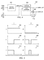
- an example encoding between signal transitions and quantization levels may be illustrated in FIGURE 5 .
- graphs 502 and 504 to represent 0, second digital signal DIGITAL_OUT may not transition during a sampling period T.
- graphs 506 and 508 to represent +1, second digital signal DIGITAL_OUT may transition from low to high during a sampling period T.
- graphs 510 and 512 represent -1, second digital signal DIGITAL_OUT may transition from high to low during a sampling period T.
- the encoding scheme shown in FIGURE 5 may provide for reduction in power in transmitting second digital signal DIGITAL_OUT.
- a significant portion of power loss in signal transmission on a digital bus occurs as a result of transitions of the digital signal.
- power loss may also be reduced by suppression transmission of control data when there is no transition in the data of second digital signal DIGITAL_OUT.
- second digital signal DIGITAL_OUT may be carried on a communication bus which is also used to carry control signals.
- second digital signal DIGITAL_OUT may be interleaved with one or more control signals.
- communication of control signals may be suppressed when the second digital signal is 0, and thus not transitioning.
- references in the appended claims to an apparatus or system or a component of an apparatus or system being adapted to, arranged to, capable of, configured to, enabled to, operable to, or operative to perform a particular function encompasses that apparatus, system, or component, whether or not it or that particular function is activated, turned on, or unlocked, as long as that apparatus, system, or component is so adapted, arranged, capable, configured, enabled, operable, or operative.
Landscapes
- Engineering & Computer Science (AREA)
- Theoretical Computer Science (AREA)
- Physics & Mathematics (AREA)
- Acoustics & Sound (AREA)
- Signal Processing (AREA)
- General Health & Medical Sciences (AREA)
- Health & Medical Sciences (AREA)
- Otolaryngology (AREA)
- Power Engineering (AREA)
- Circuit For Audible Band Transducer (AREA)
- Compression, Expansion, Code Conversion, And Decoders (AREA)
- Analogue/Digital Conversion (AREA)
- Amplifiers (AREA)
Abstract
Description
- The present disclosure relates in general to audio systems, and more particularly, to compressing a digital signal in a digital microphone system.
- Microphones are ubiquitous on many devices used by individuals, including computers, tablets, smart phones, and many other consumer devices. Generally speaking, a microphone is an electroacoustic transducer that produces an electrical signal in response to deflection of a portion (e.g., a membrane or other structure) of a microphone caused by sound incident upon the microphone.
- In a digital microphone system, an analog output signal of the microphone transducer may be processed by an analog-to-digital converter to convert the analog output signal to a digital output signal, which may be communicated over a bus to a digital audio processor for further processing. By communicating a digital signal over the bus rather than an analog signal, the audio signal may be less susceptible to noise.
- To adequately represent an audio signal with sufficient quality, the digital output signal may have numerous quantization levels. Numerous quantization levels may require a significant number of digital bits in order that each quantization level is represented by a corresponding digital code. It may be undesirable to transmit digital codes with many bits over a digital bus, particularly a serial digital bus, as communication throughput may decrease as the number of bits in digital codes increase.
- The document
US 2009/0278721 A1 describes a hybrid delta sigma ADC architecture implementing a high-resolution delta-sigma modulator with a single bit output. - The document
US 2013/0058495 A1 describes an electronic circuit for streaming pulse density modulation (PDM) signals, which are one bit modulated digital signals used in the audio field. - In accordance with the teachings of the present disclosure, certain disadvantages and problems associated with communication of a microphone signal may be reduced or eliminated.
- The invention is defined in the independent claims. The dependent claims describe embodiments of the invention.
- In accordance with embodiments of the present disclosure, a digital microphone system may include a microphone transducer and a digital processing system. The microphone transducer may be configured to generate an analog input signal indicative of audio sounds incident upon the microphone transducer. The digital processing system may be configured to convert the analog input signal into a first digital signal having a plurality of quantization levels, and, in the digital domain, process the first digital signal to compress the first digital signal into a second digital signal having fewer quantization levels than that of the first digital signal.
- In accordance with these and other embodiments of the present disclosure, a system may include a microphone transducer and a digital processing system. The microphone transducer may be configured to generate an analog input signal indicative of audio sounds incident upon the microphone transducer. The digital processing system may be configured to convert the analog input signal into a digital signal having a plurality of quantization levels, such that each quantization level of the digital signal is represented by one or more transitions or one or more absences of transitions of one or more bits of the digital signal.
- In accordance with these and other embodiments of the present disclosure, a method may include generating an analog input signal indicative of audio sounds incident upon a microphone transducer. The method may also include converting the analog input signal into a first digital signal having a plurality of quantization levels. The method may further include, in the digital domain, processing the first digital signal to compress the first digital signal into a second digital signal having fewer quantization levels than that of the first digital signal.
- In accordance with these and other embodiments of the present disclosure, a method may include generating an analog input signal indicative of audio sounds incident upon a microphone transducer. The method may also include converting the analog input signal into a digital signal having a plurality of quantization levels, such that each quantization level of the digital signal is represented by one or more transitions or one or more absences of transitions of one or more bits of the digital signal.
- In accordance with these and other embodiments of the present disclosure, an integrated circuit may include a microphone input and a processing circuit. The microphone input may be configured to receive an analog input signal indicative of audio sounds incident upon a microphone transducer. The processing circuit may be configured to convert the analog input signal into a first digital signal having a plurality of quantization levels and, in the digital domain, process the first digital signal to compress the first digital signal into a second digital signal having fewer quantization levels than that of the first digital signal.
- In accordance with these and other embodiments of the present disclosure, an integrated circuit may include a microphone input and a processing circuit. The microphone input may be configured to receive an analog input signal indicative of audio sounds incident upon a microphone transducer. The processing circuit may be configured to convert the analog input signal into a digital signal having a plurality of quantization levels, such that each quantization level is represented by one or more transitions or one or more absences of transitions of one or more bits of the digital signal.
- Technical advantages of the present disclosure may be readily apparent to one having ordinary skill in the art from the figures, description and claims included herein. The objects and advantages of the embodiments will be realized and achieved at least by the elements, features, and combinations particularly pointed out in the claims.
- It is to be understood that both the foregoing general description and the following detailed description are explanatory examples and are not restrictive of the claims set forth in this disclosure.
- A more complete understanding of the present embodiments and advantages thereof may be acquired by referring to the following description taken in conjunction with the accompanying drawings, in which like reference numbers indicate like features, and wherein:
-
FIGURE 1 illustrates a block diagram of selected components of an example audio system, in accordance with embodiments of the present disclosure; -
FIGURE 2 illustrates a block diagram of selected components of a digital microphone integrated circuit, in accordance with embodiments of the present disclosure; -
FIGURE 3 illustrates a block diagram of selected components of a delta-sigma modulator, which may be used to implement the analog-to-digital converter depicted inFIGURE 2 , in accordance with embodiments of the present disclosure; -
FIGURE 4 illustrates a block diagram of selected components of a quantizer, in accordance with embodiments of the present disclosure; and -
FIGURE 5 illustrates graphs depicting example coding of a digital signal, in accordance with embodiments of the present disclosure. -
FIGURE 1 illustrates a block diagram of selected components of anexample audio system 100, in accordance with embodiments of the present disclosure. As shown inFIGURE 1 ,audio system 100 may include amicrophone transducer 101, a digital microphone integrated circuit (IC) 105, and adigital audio processor 109.Microphone transducer 101 may comprise any system, device, or apparatus configured to convert sound incident atmicrophone transducer 101 to an electrical signal, for example an analog output signal ANALOG_OUT, wherein such sound is converted to an electrical signal using a diaphragm or membrane having an electrical capacitance that varies as based on sonic vibrations received at the diaphragm or membrane. Microphonetransducer 101 may include an electrostatic microphone, a condenser microphone, an electret microphone, a microelectromechanical systems (MEMs) microphone, or any other suitable capacitive microphone. - Digital microphone IC 105 may comprise any suitable system, device, or apparatus configured to process analog output signal ANALOG_OUT to generate a digital audio output signal DIGITAL_BUS and condition digital audio output signal DIGITAL_BUS for transmission over a bus to
digital audio processor 109. Once converted to digital audio output signal DIGITAL_BUS, the audio signal may be transmitted over significantly longer distances without being susceptible to noise as compared to an analog transmission over the same distance. In some embodiments, digital microphone IC 105 may be disposed in close proximity withmicrophone transducer 101 to ensure that the length of the analog line betweenmicrophone transducer 101 and digital microphone IC 105 is relatively short to minimize the amount of noise that can be picked up on an analog output line carrying analog output signal ANALOG_OUT. For example, in some embodiments,microphone transducer 101 and digital microphone IC 105 may be formed on the same substrate. In other embodiments,microphone transducer 101 and digital microphone IC 105 may be formed on different substrates packaged within the same integrated circuit package. -
Digital audio processor 109 may comprise any suitable system, device, or apparatus configured to process digital audio output signal for use in a digital audio system. For example,digital audio processor 109 may comprise a microprocessor, microcontroller, digital signal processor (DSP), application specific integrated circuit (ASIC), or any other device configured to interpret and/or execute program instructions and/or process data, such as digital audio output signal. -
FIGURE 2 illustrates a block diagram of selected components of digital microphone IC 105, in accordance with embodiments of the present disclosure. As shown inFIGURE 2 , digital microphone IC 105 may include a pre-amplifier 203, an analog-to-digital converter (ADC) 215, and adriver 219. Pre-amplifier 203 may receive analog output signal ANALOG_OUT via one or more input lines which may allow for receipt of a single-ended signal, differential signal, or any other suitable analog audio signal format and may comprise any suitable system, device, or apparatus configured to condition analog output signal ANALOG_OUT for processing byADC 215. The output of pre-amplifier 203 may be communicated to ADC 215 on one or more output lines. - ADC 215 may comprise any suitable system device or apparatus configured to convert an analog audio signal received at its input, to a digital signal representative of analog output signal ANALOG_OUT. ADC 215 may itself include one or more components (e.g., delta-sigma modulator, decimator, etc.) for carrying out the functionality of ADC 215.
-
Driver 219 may receive the digital signal DIGITAL_OUT output by ADC 215 and may comprise any suitable system, device, or apparatus configured to condition such digital signal (e.g., encoding into Audio Engineering Society/European Broadcasting Union (AES/EBU), Sony/Philips Digital Interface Format (S/PDIF)), in the process generating digital audio output signal DIGITAL_BUS for transmission over a bus todigital audio processor 109. InFIGURE 2 , the bus receiving digital audio output signal DIGITAL_BUS is shown as single-ended. In some embodiments,driver 219 may generate a differential digitalaudio output signal 107. -
FIGURE 3 illustrates a block diagram of selected components of a delta-sigma modulator 300, which may be used to implementADC 215 depicted inFIGURE 2 , in accordance with embodiments of the present disclosure. As shown inFIGURE 3 ,modulator 300 may include aloop filter 302, aquantizer 304, dynamic element matching circuitry (DEM) 306, a digital-to-analog converter (DAC) 308, and adelay block 312.Loop filter 302 may comprise an input summer for generating a difference between amplified analog output signal ANALOG_AMP and an analog feedback signal ANALOG_FB, and one or more integrator stages 310, such thatloop filter 302 operates as analog filter of an error signal equal to the difference between amplified analog output signal ANALOG_AMP and analog feedback signal ANALOG_FB, and generates a filtered output analog signal toquantizer 304 based on amplified analog output signal ANALOG_AMP and analog feedback signal ANALOG_FB (e.g., amplified analog output signal ANALOG_AMP plus a filtered version of analog feedback signal ANALOG_FB). The output fromloop filter 302 may be quantized by aquantizer 304 which may, as described in greater detail below, convert the analog input signal into a first digital signal having a plurality of quantization levels and, in the digital domain, process the first digital signal to compress the first digital signal into a second digital signal having fewer quantization levels than that of the first digital signal.Quantizer 304 may also be configured to generate a digital feedback signal DIGITAL_INT. Digital feedback signal DIGITAL_INT may be delayed bydelay block 312 and fed back throughDEM circuitry 306 andDAC 308 to generate analog feedback signal ANALOG_FB. -
FIGURE 4 illustrates a block diagram of selected components of aquantizer 304, in accordance with embodiments of the present disclosure. As shown inFIGURE 4 ,quantizer 304 may include amulti-bit quantizer 402, reducedquantization level quantizer 404, anddigital summer 406.Multi-bit quantizer 402 may be configured to receive the analog output fromloop filter 302, and convert the analog output into a first digital signal DIGITAL_INT having a plurality of quantization levels (e.g., more than three), as is known in the art. In some embodiments, first digital signal DIGITAL_INT may be a signal of length N, where N is a positive integer. In particular embodiments, N may be greater or equal to 3. First digital signal DIGITAL_INT may be fed back toloop filter 302. - Reduced
quantization level quantizer 404 may in turn process the first digital signal to compress first digital signal DIGITAL_INT into a second digital signal (e.g., DIGITAL_OUT) having fewer quantization levels than that of first digital signal DIGITAL_INT. In some embodiments, second digital signal DIGITAL_OUT may be a signal of length M, where M is a positive integer less than N. In particular embodiments, M may equal to 1 or 2. As a particular example, in some embodiments, reducedquantization level quantizer 404 may generate output signals having three quantization levels: a first quantization level that corresponds to an increase in the first digital signal equal to one quantization level of first digital signal DIGITAL_INT (e.g., +1), a second quantization level that corresponds to no change of the quantization level of first digital signal DIGITAL_INT (e.g., 0), and a third quantization level that corresponds to a decrease in the first digital signal equal to one quantization level of first digital signal DIGITAL_INT (e.g., -1). In this disclosure, the compression of the audio signal to three quantization levels may not lower fidelity of the analog-to-digital conversion performed bymodulator 300, as the full, uncompressed digital signal DIGITAL_INT is fed back toloop filter 302. - As shown in
FIGURE 4 , the second digital signal (e.g., DIGITAL_OUT) generated by reducedquantization level quantizer 404 may be based not only on first digital signal DIGITAL_INT, but also on a previous value of a digital signal DIGITAL_FB. Digital feedback signal DIGITAL_FB may be generated bydigital summer 406 which has the same number of quantization levels as first digital signal DIGITAL_INT, and may be equal to a previous value of digital feedback signal DIGITAL_FB plus the current value of DIGITAL_OUT. In other words, when second digital signal DIGITAL_OUT has one of three quantization levels (e.g., -1, 0, +1), digital feedback signal DIGITAL_FB is incremented by one when second digital signal DIGITAL_OUT is +1, is unchanged when second digital signal DIGITAL_OUT is 0, and is decremented by one when second digital signal DIGITAL_OUT is -1. Thus,digital summer 406 may, along withdelay block 412, serve as part of an integration/accumulation loop such that digital feedback signal DIGITAL_FB maintains a running value that approximates a current value of first digital signal DIGITAL_INT. Thus, reducedquantization level quantizer 404 may generate second digital signal DIGITAL_OUT based on the difference between first digital signal DIGITAL_INT and the previous value of digital feedback signal DIGITAL_FB. That is, if first digital signal DIGITAL_INT is one or more quantization levels more than digital feedback signal DIGITAL_FB, then reducedquantization level quantizer 404 may generate second digital signal DIGITAL_OUT as +1; if first digital signal DIGITAL_INT is one or more quantization levels less than digital feedback signal DIGITAL_FB, then reducedquantization level quantizer 404 may generate second digital signal DIGITAL_OUT as - 1; and otherwise, reducedquantization level quantizer 404 may generate second digital signal DIGITAL_OUT as 0. - A receiver of digital signal DIGITAL_OUT (e.g., digital audio processor 109), may receive the digital signal DIGITAL_OUT and reconstruct a digital signal with the same number of quantization levels as first digital signal DIGITAL_INT by integrating values of digital output signal DIGITAL_OUT.
- In some embodiments, the various quantization levels of the second digital signal DIGITAL_OUT may be represented by corresponding digital codes. For example, when the second digital signal has three possible quantization levels (-1, 0, +1), then each quantization level may be represented by a corresponding two-bit digital code. In such embodiments, remaining unused codes may be employed to represent and communicate a control signal associated with system 100 (e.g., a signal gain associated with the digital microphone system, a direct current bias associated with the digital microphone system, etc.).
- In other embodiments, quantization levels of the second digital signal DIGITAL_OUT may not be represented by a digital code, but may instead be represented by a transition or lack of transition of second digital signal DIGITAL_OUT. For example, in embodiments in which the second digital signal DIGITAL_OUT has three quantization levels, an example encoding between signal transitions and quantization levels may be illustrated in
FIGURE 5 . As shown ingraphs graphs graphs - In addition to permitting a multiple-bit signal to be carried on a single wire, the encoding scheme shown in
FIGURE 5 may provide for reduction in power in transmitting second digital signal DIGITAL_OUT. Often, a significant portion of power loss in signal transmission on a digital bus occurs as a result of transitions of the digital signal. However, in the case of the encoding scheme shown inFIGURE 5 , no transitions are present when second digital signal DIGITAL_OUT is equal to 0, and thus transmission of such value results in little or no power loss. In such embodiments, power loss may also be reduced by suppression transmission of control data when there is no transition in the data of second digital signal DIGITAL_OUT. To illustrate, in some implementations, second digital signal DIGITAL_OUT may be carried on a communication bus which is also used to carry control signals. Thus, second digital signal DIGITAL_OUT may be interleaved with one or more control signals. To prevent transitions occurring from the control signals, communication of control signals may be suppressed when the second digital signal is 0, and thus not transitioning. - This disclosure encompasses all changes, substitutions, variations, alterations, and modifications to the example embodiments herein that a person having ordinary skill in the art would comprehend. Similarly, where appropriate, the appended claims encompass all changes, substitutions, variations, alterations, and modifications to the example embodiments herein that a person having ordinary skill in the art would comprehend. Moreover, reference in the appended claims to an apparatus or system or a component of an apparatus or system being adapted to, arranged to, capable of, configured to, enabled to, operable to, or operative to perform a particular function encompasses that apparatus, system, or component, whether or not it or that particular function is activated, turned on, or unlocked, as long as that apparatus, system, or component is so adapted, arranged, capable, configured, enabled, operable, or operative.
- Particular aspects of the subject-matter disclosed herein are set out in the following numbered clauses:
- 1. A digital microphone system comprising: a microphone transducer configured to generate an analog input signal indicative of audio sounds incident upon the microphone transducer; a digital processing system configured to: convert the analog input signal into a first digital signal having a plurality of quantization levels; and in the digital domain, process the first digital signal to compress the first digital signal into a second digital signal having fewer quantization levels than that of the first digital signal.
- 2. The system of
clause 1, wherein the microphone transducer and the digital processing system are formed on a single substrate. - 3. The system of
clause 1, wherein the microphone transducer and the digital processing system are formed on different substrates packaged within the same integrated circuit package. - 4. The system of
clause 1, wherein the microphone transducer comprises a microelectromechanical systems microphone. - 5. The system of
clause 1, wherein: each quantization level of the first digital signal is represented by an N-bit digital code, wherein N is a positive integer; and each quantization level of the second digital signal is represented by an M-bit digital code, wherein M is a positive integer less than N - 6. The system of clause 5, wherein: the number of possible M-bit digital codes is more than the number of quantization levels of the second digital signal; and one or more M-bit digital codes not corresponding to quantization levels represent a control signal associated with the digital microphone system.
- 7. The system of clause 6, wherein the control signal represents a signal gain associated with the digital microphone system.
- 8. The system of clause 6, wherein the control signal represents a direct current bias associated with the digital microphone system.
- 9. The system of clause 5, wherein: the second digital signal has three quantization levels, including: a first quantization level that corresponds to an increase in the first digital signal equal to one quantization level of the first digital signal; a second quantization level that corresponds to no change of the quantization level of the first digital signal; and a third quantization level that corresponds to a decrease in the first digital signal equal to one quantization level of the first digital signal; and the quantization level of the second digital signal is represented by a transition or lack of transition of the second digital signal.
- 10. The system of clause 9, wherein the digital processing system is further configured to: communicate the second digital signal on a bus interleaved with one or more control signals; and suppress communication of control signals when the second digital signal is of the second quantization level.
- 11. A system comprising: a microphone transducer configured to generate an analog input signal indicative of audio sounds incident upon the microphone transducer; and a digital processing system configured to convert the analog input signal into a digital signal having a plurality of quantization levels, such that each quantization level is represented by one or more transitions or one or more absences of transitions of one or more bits of the digital signal.
- 12. The system of clause 11, wherein: the digital signal has three quantization levels, including: a first quantization level that corresponds to an increase in the analog input signal; a second quantization level that corresponds to no change of the analog input signal; and a third quantization level that corresponds to a decrease in the analog input signal; and the quantization level of the digital signal is represented by a transition or lack of transition of the digital signal.
- 13. The system of clause 12, wherein the digital processing system is further configured to: communicate the digital signal on a bus interleaved with one or more control signals; and suppress communication of control signals when the digital signal is of the second quantization level.
- 14. A method comprising: generating an analog input signal indicative of audio sounds incident upon a microphone transducer; converting the analog input signal into a first digital signal having a plurality of quantization levels; and in the digital domain, processing the first digital signal to compress the first digital signal into a second digital signal having fewer quantization levels than that of the first digital signal.
- 15. The method of clause 14, wherein the microphone transducer comprises a microelectromechanical systems microphone.
- 16. The method of clause 14, wherein: each quantization level of the first digital signal is represented by an N-bit digital code, wherein N is a positive integer; and each quantization level of the second digital signal is represented by an M-bit digital code, wherein M is a positive integer less than N.
- 17. The method of clause 16, wherein: the number of possible M-bit digital codes is more than the number of quantization levels of the second digital signal; and one or more M-bit digital codes not corresponding to quantization levels represent a control signal associated with the digital microphone system.
- 18. The method of clause 17, wherein the control signal represents a signal gain associated with the digital microphone system.
- 19. The method of clause 19, wherein the control signal represents a direct current bias associated with the digital microphone system.
- 20. The method of clause 16, wherein: the second digital signal has three quantization levels, including: a first quantization level that corresponds to an increase in the first digital signal equal to one quantization level of the first digital signal; a second quantization level that corresponds to no change of the quantization level of the first digital signal; and a third quantization level that corresponds to a decrease in the first digital signal equal to one quantization level of the first digital signal; and the quantization level of the second digital signal is represented by a transition or lack of transition of the second digital signal.
- 21. The method of clause 20, further comprising: communicating the second digital signal on a bus interleaved with one or more control signals; and suppressing communication of control signals when the second digital signal is of the second quantization level.
- 22. A method comprising: generating an analog input signal indicative of audio sounds incident upon a microphone transducer; and converting the analog input signal into a digital signal having a plurality of quantization levels, such that each quantization level is represented by one or more transitions or one or more absences of transitions of one or more bits of the digital signal.
- 23. The method of clause 22, wherein: the digital signal has three quantization levels, including: a first quantization level that corresponds to an increase in the analog input signal; a second quantization level that corresponds to no change of the analog input signal; and a third quantization level that corresponds to a decrease in the analog input signal; and the quantization level of the digital signal is represented by a transition or lack of transition of the digital signal.
- 24. The method of clause 23, further comprising: communicating the digital signal on a bus interleaved with one or more control signals; and suppressing communication of control signals when the digital signal is of the second quantization level.
- 25. An integrated circuit comprising: a microphone input configured to receive an analog input signal indicative of audio sounds incident upon a microphone transducer; and a processing circuit configured to: convert the analog input signal into a first digital signal having a plurality of quantization levels; and in the digital domain, process the first digital signal to compress the first digital signal into a second digital signal having fewer quantization levels than that of the first digital signal.
- 26. The integrated circuit of
clause 1, wherein the microphone transducer comprises a microelectromechanical systems microphone. - 27. The integrated circuit of
clause 1, wherein: each quantization level of the first digital signal is represented by an N-bit digital code, wherein N is a positive integer; and each quantization level of the second digital signal is represented by an M-bit digital code, wherein M is a positive integer less than N - 28. The integrated circuit of clause 27, wherein: the number of possible M-bit digital codes is more than the number of quantization levels of the second digital signal; and one or more M-bit digital codes not corresponding to quantization levels represent a control signal associated with the digital microphone system.
- 29. The integrated circuit of clause 28, wherein the control signal represents a signal gain associated with the digital microphone system.
- 30. The integrated circuit of clause 28, wherein the control signal represents a direct current bias associated with the digital microphone system.
- 31. The integrated circuit of clause 27, wherein: the second digital signal has three quantization levels, including: a first quantization level that corresponds to an increase in the first digital signal equal to one quantization level of the first digital signal; a second quantization level that corresponds to no change of the quantization level of the first digital signal; and a third quantization level that corresponds to a decrease in the first digital signal equal to one quantization level of the first digital signal; and the quantization level of the second digital signal is represented by a transition or lack of transition of the second digital signal.
- 32. The integrated circuit of clause 31, wherein the processing circuit is further configured to: communicate the second digital signal on a bus interleaved with one or more control signals; and suppress communication of control signals when the second digital signal is of the second quantization level.
- 33. An integrated circuit comprising: a microphone input configured to receive an analog input signal indicative of audio sounds incident upon a microphone transducer; and a processing circuit configured to convert the analog input signal into a digital signal having a plurality of quantization levels, such that each quantization level is represented by one or more transitions or one or more absences of transitions of one or more bits of the digital signal.
- 34. The integrated circuit of clause 33, wherein: the digital signal has three quantization levels, including: a first quantization level that corresponds to an increase in the analog input signal; a second quantization level that corresponds to no change of the analog input signal; and a third quantization level that corresponds to a decrease in the analog input signal; and the quantization level of the digital signal is represented by a transition or lack of transition of the digital signal.
- 35. The integrated circuit of clause 34, wherein the processing circuit is further configured to: communicate the digital signal on a bus interleaved with one or more control signals; and suppress communication of control signals when the digital signal is of the second quantization level.
- All examples and conditional language recited herein are intended for pedagogical objects to aid the reader in understanding the disclosure and the concepts contributed by the inventor to furthering the art, and are construed as being without limitation to such specifically recited examples and conditions. Although embodiments of the present disclosure have been described in detail, it should be understood that various changes, substitutions, and alterations could be made hereto without departing from the scope of the disclosure.
Claims (9)
- A system comprising:a microphone transducer (101) configured to generate an analog input signal indicative of audio sounds incident upon the microphone transducer (101); anda digital processing system configured to convert the analog input signal into a digital signal (DIGITAL_OUT) having a plurality of quantization levels,characterized in thatthe conversion is performed such that each quantization level is represented by one or more transitions or one or more absences of transitions of one or more bits of the digital signal (DIGITAL_OUT).
- The system of Claim 1, wherein:the digital signal (DIGITAL_OUT) has three quantization levels, including:a first quantization level that corresponds to an increase in the analog input signal;a second quantization level that corresponds to no change of the analog input signal; anda third quantization level that corresponds to a decrease in the analog input signal; andthe quantization level of the digital signal (DIGITAL_OUT) is represented by a transition or lack of transition of the digital signal (DIGITAL_OUT).
- The system of Claim 2, wherein the digital processing system is further configured to:communicate the digital signal (DIGITAL_OUT) on a bus interleaved with one or more control signals; andsuppress communication of control signals when the digital signal (DIGITAL_OUT) is of the second quantization level.
- A method comprising:generating an analog input signal indicative of audio sounds incident upon a microphone transducer (101); andconverting the analog input signal into a digital signal (DIGITAL_OUT) having a plurality of quantization levels,characterized in thatthe conversion is performed such that each quantization level is represented by one or more transitions or one or more absences of transitions of one or more bits of the digital signal (DIGITAL_OUT).
- The method of Claim 4, wherein:the digital signal (DIGITAL_OUT) has three quantization levels, including:a first quantization level that corresponds to an increase in the analog input signal;a second quantization level that corresponds to no change of the analog input signal; anda third quantization level that corresponds to a decrease in the analog input signal; andthe quantization level of the digital signal (DIGITAL_OUT) is represented by a transition or lack of transition of the digital signal (DIGITAL_OUT).
- The method of Claim 5, further comprising:communicating the digital signal (DIGITAL_OUT) on a bus interleaved with one or more control signals; andsuppressing communication of control signals when the digital signal (DIGITAL_OUT) is of the second quantization level.
- An integrated circuit comprising:a microphone input configured to receive an analog input signal indicative of audio sounds incident upon a microphone transducer (101); anda processing circuit configured to convert the analog input signal into a digital signal (DIGITAL_OUT) having a plurality of quantization levels,characterized in thatthe conversion is performed such that each quantization level is represented by one or more transitions or one or more absences of transitions of one or more bits of the digital signal (DIGITAL_OUT).
- The integrated circuit of Claim 7, wherein:the digital signal (DIGITAL_OUT) has three quantization levels, including:a first quantization level that corresponds to an increase in the analog input signal;a second quantization level that corresponds to no change of the analog input signal; anda third quantization level that corresponds to a decrease in the analog input signal; andthe quantization level of the digital signal (DIGITAL_OUT) is represented by a transition or lack of transition of the digital signal (DIGITAL_OUT).
- The integrated circuit of Claim 8, wherein the processing circuit is further configured to:communicate the digital signal (DIGITAL_OUT) on a bus interleaved with one or more control signals; andsuppress communication of control signals when the digital signal (DIGITAL_OUT) is of the second quantization level.
Applications Claiming Priority (2)
| Application Number | Priority Date | Filing Date | Title |
|---|---|---|---|
| US201361810075P | 2013-04-09 | 2013-04-09 | |
| EP14722934.8A EP2984760A2 (en) | 2013-04-09 | 2014-04-08 | Systems and methods for compressing a digital signal in a digital microphone system |
Related Parent Applications (1)
| Application Number | Title | Priority Date | Filing Date |
|---|---|---|---|
| EP14722934.8A Division EP2984760A2 (en) | 2013-04-09 | 2014-04-08 | Systems and methods for compressing a digital signal in a digital microphone system |
Publications (1)
| Publication Number | Publication Date |
|---|---|
| EP3166331A1 true EP3166331A1 (en) | 2017-05-10 |
Family
ID=50640043
Family Applications (4)
| Application Number | Title | Priority Date | Filing Date |
|---|---|---|---|
| EP14722934.8A Withdrawn EP2984760A2 (en) | 2013-04-09 | 2014-04-08 | Systems and methods for compressing a digital signal in a digital microphone system |
| EP14721718.6A Withdrawn EP2984759A2 (en) | 2013-04-09 | 2014-04-08 | Systems and methods for generating a digital output signal in a digital microphone system |
| EP16183887.5A Withdrawn EP3166331A1 (en) | 2013-04-09 | 2014-04-08 | Systems and methods for compressing a digital signal in a digital microphone system |
| EP16183886.7A Withdrawn EP3166330A1 (en) | 2013-04-09 | 2014-04-08 | Systems and methods for compressing a digital signal in a digital microphone system |
Family Applications Before (2)
| Application Number | Title | Priority Date | Filing Date |
|---|---|---|---|
| EP14722934.8A Withdrawn EP2984760A2 (en) | 2013-04-09 | 2014-04-08 | Systems and methods for compressing a digital signal in a digital microphone system |
| EP14721718.6A Withdrawn EP2984759A2 (en) | 2013-04-09 | 2014-04-08 | Systems and methods for generating a digital output signal in a digital microphone system |
Family Applications After (1)
| Application Number | Title | Priority Date | Filing Date |
|---|---|---|---|
| EP16183886.7A Withdrawn EP3166330A1 (en) | 2013-04-09 | 2014-04-08 | Systems and methods for compressing a digital signal in a digital microphone system |
Country Status (4)
| Country | Link |
|---|---|
| US (5) | US9571931B1 (en) |
| EP (4) | EP2984760A2 (en) |
| CN (2) | CN105379123A (en) |
| WO (2) | WO2014168934A2 (en) |
Families Citing this family (24)
| Publication number | Priority date | Publication date | Assignee | Title |
|---|---|---|---|---|
| CN105379123A (en) | 2013-04-09 | 2016-03-02 | 美国思睿逻辑有限公司 | Systems and methods for generating digital output signal in digital microphone system |
| GB2513406B (en) | 2013-04-26 | 2016-01-20 | Cirrus Logic Int Semiconductor Ltd | Signal processing for MEMS capacitive transducers |
| US9626981B2 (en) | 2014-06-25 | 2017-04-18 | Cirrus Logic, Inc. | Systems and methods for compressing a digital signal |
| GB2530605B (en) * | 2014-06-25 | 2018-10-24 | Cirrus Logic Inc | Systems and methods for compressing a digital signal |
| US10200794B2 (en) * | 2014-12-31 | 2019-02-05 | Invensense, Inc. | Ultrasonic operation of a digital microphone |
| JP2016184792A (en) * | 2015-03-25 | 2016-10-20 | エスアイアイ・セミコンダクタ株式会社 | ΔΣ modulator |
| US10545561B2 (en) * | 2016-08-10 | 2020-01-28 | Cirrus Logic, Inc. | Multi-path digitation based on input signal fidelity and output requirements |
| US9936304B2 (en) * | 2016-08-23 | 2018-04-03 | Infineon Technologies Ag | Digital silicon microphone with configurable sensitivity, frequency response and noise transfer function |
| US10236018B2 (en) * | 2017-03-01 | 2019-03-19 | Soltare Inc. | Systems and methods for detection of a target sound |
| CA3003840C (en) | 2017-05-03 | 2025-02-04 | Soltare Inc. | Audio processing for vehicle sensory systems |
| WO2019226958A1 (en) | 2018-05-24 | 2019-11-28 | The Research Foundation For The State University Of New York | Capacitive sensor |
| US10833697B2 (en) * | 2018-09-06 | 2020-11-10 | Mediatek Singapore Pte. Ltd. | Methods and circuits for suppressing quantization noise in digital-to-analog converters |
| US10972319B2 (en) * | 2018-09-12 | 2021-04-06 | Texas Instruments Incorporated | Clockless decision feedback equalization (DFE) for multi-level signals |
| CN109348391A (en) * | 2018-10-09 | 2019-02-15 | 晶晨半导体(上海)股份有限公司 | Microphone detection method, system and microphone |
| CN109068256A (en) * | 2018-10-09 | 2018-12-21 | 晶晨半导体(上海)股份有限公司 | Detection method, system, microphone and the intelligent sound box of microphone |
| CN109600704A (en) * | 2018-11-20 | 2019-04-09 | 晶晨半导体(上海)股份有限公司 | A method of the microphone rosin joint inspection based on digit pulse |
| US11438697B2 (en) | 2019-06-07 | 2022-09-06 | Cirrus Logic, Inc. | Low-latency audio output with variable group delay |
| US10701486B1 (en) | 2019-06-07 | 2020-06-30 | Cirrus Logic, Inc. | Low-latency audio output with variable group delay |
| US12091313B2 (en) | 2019-08-26 | 2024-09-17 | The Research Foundation For The State University Of New York | Electrodynamically levitated actuator |
| WO2021061884A1 (en) * | 2019-09-24 | 2021-04-01 | Analog Devices, Inc. | Increasing power efficiency in a digital feedback class d driver |
| CN110944280B (en) * | 2019-11-13 | 2021-08-31 | 潍坊歌尔微电子有限公司 | A kind of noise test system and test method for digital microphone |
| US11418890B1 (en) * | 2021-04-15 | 2022-08-16 | Knowles Electronics, Llc | Digital sensors, electrical circuits and methods |
| US11906997B2 (en) * | 2021-05-14 | 2024-02-20 | Taiwan Semiconductor Manufacturing Company, Ltd. | Low-dropout (LDO) voltage regulator including amplifier and decoupling capacitor |
| CN116761116B (en) * | 2023-06-08 | 2025-10-03 | 浙江大学 | A low-voltage domain powered digital microphone interface circuit with fully dynamic gain adjustment |
Citations (5)
| Publication number | Priority date | Publication date | Assignee | Title |
|---|---|---|---|---|
| US20030095606A1 (en) * | 2001-11-16 | 2003-05-22 | Horowitz Mark A. | Method and apparatus for multi-level signaling |
| US20090278721A1 (en) | 2008-05-09 | 2009-11-12 | Asahi Kasei Mircrodevices Corporation | Hybrid delta-sigma adc |
| US20100057474A1 (en) * | 2008-06-19 | 2010-03-04 | Hongwei Kong | Method and system for digital gain processing in a hardware audio codec for audio transmission |
| GB2485270A (en) * | 2010-11-04 | 2012-05-09 | Epcos Ag | Microphone arrangement |
| US20130058495A1 (en) | 2011-09-01 | 2013-03-07 | Claus Erdmann Furst | System and A Method For Streaming PDM Data From Or To At Least One Audio Component |
Family Cites Families (61)
| Publication number | Priority date | Publication date | Assignee | Title |
|---|---|---|---|---|
| US4631749A (en) | 1984-06-22 | 1986-12-23 | Heath Company | ROM compensated microphone |
| KR890004441B1 (en) | 1984-08-30 | 1989-11-03 | 후지쓰 가부시끼가이샤 | Automatic cording circuit |
| NL8600862A (en) * | 1986-04-04 | 1987-11-02 | Philips Nv | CODING DEVICE. |
| US5247210A (en) | 1986-11-12 | 1993-09-21 | Crystal Semiconductor | Method and circuitry for decreasing the recovery time of an MOS differential voltage comparator |
| NL9100379A (en) | 1991-03-01 | 1992-10-01 | Philips Nv | SIGMA DELTA MODULATOR. |
| US5603088A (en) | 1995-02-28 | 1997-02-11 | Motorola, Inc. | Method and apparatus for determining a quality level of an analog signal in a radio communication system |
| TW379503B (en) | 1998-09-15 | 2000-01-11 | Mentor Data System Inc | Method and apparatus of video compression and reformatting to increase video channel utilization |
| CN1138254C (en) * | 2001-03-19 | 2004-02-11 | 北京阜国数字技术有限公司 | Audio signal comprssing coding/decoding method based on wavelet conversion |
| JP2002314354A (en) | 2001-04-10 | 2002-10-25 | Mitsubishi Electric Corp | Multistage amplifier circuit |
| US6933871B2 (en) | 2001-09-17 | 2005-08-23 | Cirrus Logic, Inc. | Feedback steering delta-sigma modulators and systems using the same |
| US6724332B1 (en) | 2002-08-13 | 2004-04-20 | Cirrus Logic, Inc. | Noise shaping circuits and methods with feedback steering overload compensation and systems using the same |
| US7116721B1 (en) | 2002-05-20 | 2006-10-03 | Cirrus Logic, Inc. | Delta-sigma modulators with integral digital low-pass filtering |
| US6738004B2 (en) | 2002-08-15 | 2004-05-18 | Cirrus Logic, Inc. | Method and system of integrating a mismatch noise shaper into the main loop of a delta-sigma modulator |
| US6809572B2 (en) | 2002-09-18 | 2004-10-26 | Cirrus Logic, Incorporated | Integrated circuit with automatic polarity detection and configuration |
| US6956919B2 (en) | 2002-11-12 | 2005-10-18 | Cirrus Logic, Inc. | Single clock data communication in direct stream digital system |
| US6822594B1 (en) | 2003-10-09 | 2004-11-23 | Cirrus Logic, Inc. | Overload protection and stability for high order 1-bit delta-sigma modulators |
| DE602004031044D1 (en) | 2003-11-24 | 2011-02-24 | Epcos Pte Ltd | MICROPHONE WITH AN INTEGRAL MULTIPLE LEVEL QUANTIZER AND BIT IMPROVERS |
| US7196647B2 (en) | 2004-01-16 | 2007-03-27 | Cirrus Logic, Inc. | Signal processing with look-ahead modulator noise quantization minimization |
| US7187312B2 (en) | 2004-01-16 | 2007-03-06 | Cirrus Logic, Inc. | Look-ahead delta sigma modulator having an infinite impulse response filter with multiple look-ahead outputs |
| US6879275B1 (en) | 2004-01-16 | 2005-04-12 | Cirrus Logic, Inc. | Signal processing with a look-ahead modulator having time weighted error values |
| US7009543B2 (en) | 2004-01-16 | 2006-03-07 | Cirrus Logic, Inc. | Multiple non-monotonic quantizer regions for noise shaping |
| US7170434B2 (en) * | 2004-01-16 | 2007-01-30 | Cirrus Logic, Inc. | Look-ahead delta sigma modulator with quantization using natural and pattern loop filter responses |
| US7084798B2 (en) | 2004-01-16 | 2006-08-01 | Cirrus Logic, Inc. | Look-ahead delta sigma modulators with quantizer input approximations |
| US7148830B2 (en) | 2004-01-26 | 2006-12-12 | Cirrus Logic, Inc. | Look-ahead delta sigma modulator with pruning of output candidate vectors using quantization error minimization pruning techniques |
| US7138934B2 (en) | 2004-01-26 | 2006-11-21 | Cirrus Logic, Inc. | Pattern biasing for look-ahead delta sigma modulators |
| US7394410B1 (en) | 2004-02-13 | 2008-07-01 | Samplify Systems, Inc. | Enhanced data converters using compression and decompression |
| US7081843B2 (en) | 2004-07-19 | 2006-07-25 | Cirrus Logic, Inc. | Overload protection for look-ahead delta sigma modulators |
| GB2425668B (en) | 2005-01-17 | 2009-02-25 | Wolfson Microelectronics Plc | Pulse width modulator quantisation circuit |
| US7358881B2 (en) | 2005-07-22 | 2008-04-15 | Cirrus Logic, Inc. | Quantizer overload prevention for feed-back type delta-sigma modulators |
| US7164379B1 (en) | 2005-11-30 | 2007-01-16 | General Electric Company | Pipeline analog to digital converter |
| US7183957B1 (en) | 2005-12-30 | 2007-02-27 | Cirrus Logic, Inc. | Signal processing system with analog-to-digital converter using delta-sigma modulation having an internal stabilizer loop |
| US7298305B2 (en) | 2006-03-24 | 2007-11-20 | Cirrus Logic, Inc. | Delta sigma modulator analog-to-digital converters with quantizer output prediction and comparator reduction |
| JP2009537817A (en) * | 2006-05-17 | 2009-10-29 | エヌエックスピー ビー ヴィ | Capacitance MEMS sensor device |
| US7903835B2 (en) | 2006-10-18 | 2011-03-08 | The Research Foundation Of State University Of New York | Miniature non-directional microphone |
| US7450047B1 (en) | 2007-09-06 | 2008-11-11 | National Semiconductor Corporation | Sigma-delta modulator with DAC resolution less than ADC resolution and increased dynamic range |
| TWI351683B (en) | 2008-01-16 | 2011-11-01 | Mstar Semiconductor Inc | Speech enhancement device and method for the same |
| GB2459864A (en) | 2008-05-07 | 2009-11-11 | Wolfson Microelectronics Plc | Filtered bias voltage for a MEMS capacitive transducer circuit |
| GB2459862B (en) | 2008-05-07 | 2010-06-30 | Wolfson Microelectronics Plc | Capacitive transducer circuit and method |
| DE102008024897B3 (en) | 2008-05-28 | 2010-01-07 | Austriamicrosystems Ag | Sigma-delta converters and signal processing methods |
| US7770349B2 (en) * | 2008-07-14 | 2010-08-10 | Usg Interiors, Inc. | Seismic clip for grid tee control joint |
| JP2011004327A (en) | 2009-06-22 | 2011-01-06 | Hamamatsu Photonics Kk | Integration circuit and photodetection device |
| JP5479799B2 (en) | 2009-07-23 | 2014-04-23 | ルネサスエレクトロニクス株式会社 | Semiconductor device |
| GB0919673D0 (en) | 2009-11-10 | 2009-12-23 | Skype Ltd | Gain control for an audio signal |
| EP2432249A1 (en) * | 2010-07-02 | 2012-03-21 | Knowles Electronics Asia PTE. Ltd. | Microphone |
| EP2421281A3 (en) | 2010-08-17 | 2012-04-04 | Nxp B.V. | Circuit and method for monitoring a capacitive signal source |
| US8502717B2 (en) | 2010-11-19 | 2013-08-06 | Fortemedia, Inc. | Analog-to-digital converter, sound processing device, and method for analog-to-digital conversion |
| WO2012119610A1 (en) * | 2011-03-04 | 2012-09-13 | Sony Ericsson Mobile Communications Ab | Method for driving a condenser microphone |
| US9236837B2 (en) | 2011-08-25 | 2016-01-12 | Infineon Technologies Ag | System and method for low distortion capacitive signal source amplifier |
| US8638249B2 (en) | 2012-04-16 | 2014-01-28 | Infineon Technologies Ag | System and method for high input capacitive signal amplifier |
| US9516443B2 (en) | 2012-06-07 | 2016-12-06 | Cirrus Logic International Semiconductor Ltd. | Non-linear control of loudspeakers |
| US8604861B1 (en) * | 2012-06-19 | 2013-12-10 | Infineon Technologies Ag | System and method for a switched capacitor circuit |
| GB2508612B (en) | 2012-12-04 | 2015-12-09 | Cirrus Logic Int Semiconductor Ltd | Interpretation circuit for a switch unit comprising a plurality of register blocks |
| CN105379123A (en) | 2013-04-09 | 2016-03-02 | 美国思睿逻辑有限公司 | Systems and methods for generating digital output signal in digital microphone system |
| US9130070B2 (en) * | 2013-04-25 | 2015-09-08 | Analog Devices, Inc. | Four-stage circuit architecture for detecting pulsed signals |
| GB2513406B (en) | 2013-04-26 | 2016-01-20 | Cirrus Logic Int Semiconductor Ltd | Signal processing for MEMS capacitive transducers |
| US9425757B2 (en) | 2013-05-15 | 2016-08-23 | Infineon Technologies Ag | Apparatus and method for controlling an amplification gain of an amplifier, and a digitizer circuit and microphone assembly |
| US8907829B1 (en) * | 2013-05-17 | 2014-12-09 | Cirrus Logic, Inc. | Systems and methods for sampling in an input network of a delta-sigma modulator |
| CN104469608A (en) | 2013-09-25 | 2015-03-25 | 罗伯特·博世有限公司 | System and method for adjusting microphone functionality |
| US9076554B1 (en) | 2014-01-21 | 2015-07-07 | Aeroflex Colorado Springs Inc. | Low-noise low-distortion signal acquisition circuit and method with reduced area utilization |
| GB2530605B (en) | 2014-06-25 | 2018-10-24 | Cirrus Logic Inc | Systems and methods for compressing a digital signal |
| US9626981B2 (en) | 2014-06-25 | 2017-04-18 | Cirrus Logic, Inc. | Systems and methods for compressing a digital signal |
-
2014
- 2014-04-08 CN CN201480031934.XA patent/CN105379123A/en active Pending
- 2014-04-08 US US14/247,987 patent/US9571931B1/en active Active
- 2014-04-08 EP EP14722934.8A patent/EP2984760A2/en not_active Withdrawn
- 2014-04-08 EP EP14721718.6A patent/EP2984759A2/en not_active Withdrawn
- 2014-04-08 US US14/247,771 patent/US10375475B2/en active Active
- 2014-04-08 US US14/248,054 patent/US9419562B1/en active Active
- 2014-04-08 WO PCT/US2014/033302 patent/WO2014168934A2/en not_active Ceased
- 2014-04-08 WO PCT/US2014/033314 patent/WO2014168939A2/en not_active Ceased
- 2014-04-08 EP EP16183887.5A patent/EP3166331A1/en not_active Withdrawn
- 2014-04-08 EP EP16183886.7A patent/EP3166330A1/en not_active Withdrawn
- 2014-04-08 US US14/247,686 patent/US20140301571A1/en not_active Abandoned
- 2014-04-08 CN CN201480031974.4A patent/CN105264777B/en active Active
- 2014-04-08 US US14/248,035 patent/US9332345B1/en not_active Expired - Fee Related
Patent Citations (5)
| Publication number | Priority date | Publication date | Assignee | Title |
|---|---|---|---|---|
| US20030095606A1 (en) * | 2001-11-16 | 2003-05-22 | Horowitz Mark A. | Method and apparatus for multi-level signaling |
| US20090278721A1 (en) | 2008-05-09 | 2009-11-12 | Asahi Kasei Mircrodevices Corporation | Hybrid delta-sigma adc |
| US20100057474A1 (en) * | 2008-06-19 | 2010-03-04 | Hongwei Kong | Method and system for digital gain processing in a hardware audio codec for audio transmission |
| GB2485270A (en) * | 2010-11-04 | 2012-05-09 | Epcos Ag | Microphone arrangement |
| US20130058495A1 (en) | 2011-09-01 | 2013-03-07 | Claus Erdmann Furst | System and A Method For Streaming PDM Data From Or To At Least One Audio Component |
Non-Patent Citations (4)
| Title |
|---|
| ANONYMOUS: "Non-return-to-zero", 18 August 2010 (2010-08-18), XP055193887, Retrieved from the Internet <URL:http://en.wikipedia.org/w/index.php?title=Non-return-to-zero&oldid=379590899> [retrieved on 20150605] * |
| ANONYMOUS: "SLIMbus - Wikipedia", 19 February 2013 (2013-02-19), XP055361583, Retrieved from the Internet <URL:https://en.wikipedia.org/w/index.php?title=SLIMbus&oldid=539008572> [retrieved on 20170404] * |
| ANONYMOUS: "USB - Wikipedia, the free encyclopedia", 30 December 2012 (2012-12-30), XP055297292, Retrieved from the Internet <URL:https://en.wikipedia.org/w/index.php?title=USB&oldid=530464826> [retrieved on 20160824] * |
| GOJKO BABIC: "Signal Encoding Techniques Presentation C CSE 3461/5461: Introduction to Computer Networking & Internet Technologies", 9 April 2012 (2012-04-09), XP055361422, Retrieved from the Internet <URL:http://web.cse.ohio-state.edu/~srinivasan.115/cse3461-5461/Cse3461.C.SignalEncoding.09-04-2012.pdf> [retrieved on 20170404] * |
Also Published As
| Publication number | Publication date |
|---|---|
| US9571931B1 (en) | 2017-02-14 |
| US20140301572A1 (en) | 2014-10-09 |
| EP2984760A2 (en) | 2016-02-17 |
| WO2014168934A4 (en) | 2015-03-12 |
| CN105264777A (en) | 2016-01-20 |
| WO2014168939A2 (en) | 2014-10-16 |
| CN105264777B (en) | 2019-07-09 |
| EP2984759A2 (en) | 2016-02-17 |
| EP3166330A1 (en) | 2017-05-10 |
| WO2014168934A3 (en) | 2014-12-31 |
| US10375475B2 (en) | 2019-08-06 |
| CN105379123A (en) | 2016-03-02 |
| US9332345B1 (en) | 2016-05-03 |
| WO2014168934A2 (en) | 2014-10-16 |
| WO2014168939A4 (en) | 2015-04-16 |
| US20140301571A1 (en) | 2014-10-09 |
| WO2014168939A3 (en) | 2015-01-29 |
| US9419562B1 (en) | 2016-08-16 |
Similar Documents
| Publication | Publication Date | Title |
|---|---|---|
| US10375475B2 (en) | Systems and methods for compressing a digital signal in a digital microphone system | |
| EP3161964B1 (en) | Systems and methods for compressing a digital signal | |
| KR101840730B1 (en) | Bandwidth extension of oversampled analog-to-digital converters by means of gain boosting | |
| KR102514329B1 (en) | Digital silicon microphone with interpolation | |
| CN1879446A (en) | Microphone including integral multilevel quantizer and single bit conversion device | |
| US7928886B2 (en) | Emulation of analog-to-digital converter characteristics | |
| KR101228991B1 (en) | Adaptive dynamic range control | |
| US11799494B2 (en) | Delta-sigma modulator, delta-sigma digital-analog converter, and method for operating a delta-sigma modulator and a delta-sigma digital-analog converter | |
| US10972123B1 (en) | Signal processing structure | |
| US9172494B2 (en) | Modulator device | |
| CN115379356B (en) | A low-latency noise reduction circuit, method and active noise reduction earphone | |
| GB2530605A (en) | Systems and methods for compressing a digital signal | |
| CN112929780B (en) | Audio chip and earphone of noise reduction processing | |
| WO2021015955A1 (en) | Increased noise performance using quantizer code suppression | |
| WO2003023970A2 (en) | Serial data interface with reduced power consumption | |
| Lyon | Microphone with Improved Dynamic Range | |
| JP2010109422A (en) | Digital signal processor | |
| JP2008148212A (en) | Communication apparatus |
Legal Events
| Date | Code | Title | Description |
|---|---|---|---|
| PUAI | Public reference made under article 153(3) epc to a published international application that has entered the european phase |
Free format text: ORIGINAL CODE: 0009012 |
|
| STAA | Information on the status of an ep patent application or granted ep patent |
Free format text: STATUS: THE APPLICATION HAS BEEN PUBLISHED |
|
| AC | Divisional application: reference to earlier application |
Ref document number: 2984760 Country of ref document: EP Kind code of ref document: P |
|
| AK | Designated contracting states |
Kind code of ref document: A1 Designated state(s): AL AT BE BG CH CY CZ DE DK EE ES FI FR GB GR HR HU IE IS IT LI LT LU LV MC MK MT NL NO PL PT RO RS SE SI SK SM TR |
|
| STAA | Information on the status of an ep patent application or granted ep patent |
Free format text: STATUS: REQUEST FOR EXAMINATION WAS MADE |
|
| 17P | Request for examination filed |
Effective date: 20171019 |
|
| RBV | Designated contracting states (corrected) |
Designated state(s): AL AT BE BG CH CY CZ DE DK EE ES FI FR GB GR HR HU IE IS IT LI LT LU LV MC MK MT NL NO PL PT RO RS SE SI SK SM TR |
|
| STAA | Information on the status of an ep patent application or granted ep patent |
Free format text: STATUS: EXAMINATION IS IN PROGRESS |
|
| 17Q | First examination report despatched |
Effective date: 20200107 |
|
| STAA | Information on the status of an ep patent application or granted ep patent |
Free format text: STATUS: THE APPLICATION HAS BEEN WITHDRAWN |
|
| 18W | Application withdrawn |
Effective date: 20200204 |